
Active Reduction of Apparent Cable Capacitance

1
Oak Ridge National Laboratory, Oak Ridge, TN 37831, USA
2
Department of Electrical Engineering and Computer Science, University of Tennessee, Knoxville, TN 37996, USA
3
Valtok, Karns, TN 37931, USA
*
Author to whom correspondence should be addressed.
Sensors 2023, 23(19), 8319; https://doi.org/10.3390/s23198319
Submission received: 16 September 2023
/
Revised: 2 October 2023
/
Accepted: 4 October 2023
/
Published: 8 October 2023
(This article belongs to the Section Industrial Sensors)
Abstract
:This paper presents a method for reducing apparent cable capacitance seen by sensors. The proposed method is designed for sensing in extreme environments including ultra-high temperatures, but can be applied in benign environments as well. By reducing the cable capacitance, high speed signals can be transmitted over longer distances, allowing the application of advanced control systems that require high bandwidth data for stable operation. A triaxial cable with an associated guard circuit is developed that actively reduces cable capacitance while also rejecting extraneous electric and magnetic interference on the signal. The active capacitance reduction method developed is tested experimentally and shown to reduce apparent cable capacitance to two percent of the static value.
1. Introduction
The extreme environments encountered in aerospace, fusion energy, fission energy, and concentrated solar energy have severe restrictions on materials that can be used in sensors.
Some applications for extreme environment sensors are high temperature magnetic bearings developed by the National Aeronautical and Space Administration (NASA) [1] and magnetically levitated molten salt pumps being developed by the Department of Energy (DOE) for molten salt reactors (MSRs), fusion energy, and concentrated solar energy [2,3]. In both applications, it is required to dynamically measure the location of a rotor at high sample rates to stabilize the magnetic bearings using feedback control.
In the case of the DOE molten salt pump, the design removes the need for rotating seals and roller element bearings, which are components with a high failure rate. A major challenge in this design is the requirement for the rotor position sensors to be in close physical proximity to the rotor. In this application, temperatures can reach 800 °C, well above the Curie temperature of most materials. In addition, the salt chemistry is highly corrosive, which requires using corrosion barriers to protect materials that are not salt compatible [2,3].
The cabling connecting the sensors in the extreme environment to the signal processing and data acquisition also has similar design challenges. In addition, the electronic components need to be in a relatively benign environment, which is often far from the sensor. Components like magnetic bearings require high frequency position measurements for stable operation. As the cable length increases, the apparent capacitance (as seen by the sensor) also increases. The RS-232-C standard limits cable lengths to 50 m or below 2500 pF [4]. In [5], the empirically determined maximum lengths for RS-232 cables sending data a 19.2 kilobaud are about ten times the RS-232-C standard. High performance mainframe cables developed by IBM support 330 Mb/s data transmission rates at cable lengths up to 20 m [6]. The maximum cable length for contactor control cables is calculated in [7]. In all the preceding references, a common theme is that cable capacitance limits performance. Increasing cable capacitance reduces the overall sensor bandwidth, reduces data transmission rates, and decreases the signal-to-noise ratio. The need for reducing the apparent cable capacitance for stable high temperature magnetic bearing control motivates this work.
In addition to low capacitance, the cables need to shield against electromagnetic interference from the electric motor providing torque for the rotor, pulse width modulated magnetic bearing drive signals, along with magnetic fields from both motor and magnetic bearings. Coaxial cables shield the signal from extraneous electric and magnetic fields, because it is imposed on the center conductor and shield as common mode noise, which is then rejected by the differential amplifier used to increase the sensor signal amplitude. Figure 1 shows a typical implementation of a coaxial cable. represents the sensor which is driven by the voltage .
The internal capacitance of coaxial cable geometry shown in Figure 2 is given by
where C is the cable capacitance, l is the cable length, F/m is the dielectric constant of free space, is the relative dielectric constant of the insulation, D is the inside diameter of the shield, and d is the outer diameter of the signal conductor.
Coaxial cable capacitance ranges from 30 pF/m to 100 pF/m depending on type [8]. Expected wire-end capacitance will be around 700 pF for a 7.4 m length, an approximate length expected from sensor at the pump to the electronics package. This value of capacitance is remarkably high and can pose a performance and stability problem for the inductive sensor.
The standard approach to reducing cable capacitance is to use a guarded circuit [9,10]. Essentially, the shield is driven with a buffered input signal reducing the voltage difference between the shield and signal. Applied to coaxial cables, this reduces leakage and internal capacitance. Figure 3 shows a coaxial cable guard circuit from [9].
In the guard circuit, the coaxial shield is no longer grounded, which means that extraneous electrical and magnetic interference cause a voltage differential between the shield and central conductor. This means that the noise is no longer common mode, and cannot be rejected by the differential amplifier. Additionally, the amplifiers output impedance is not zero, which means that extraneous signals can be injected through this route. To address these limitations of coaxial cables, a triaxial cable with two independent shields and an inner conductor was chosen to transmit the sensor signal. The triaxial cable geometry is shown in Figure 4.
The triaxial cable’s inner shield can be driven like the guard circuit, but the cable also has another outermost shield that is ground connected to prevent the inner shield from receiving extraneous voltages and currents.
Cable Insulation
For high temperature applications, it is impossible to use plastic insulated cables. Instead, mineral insulated cables are typically used. Most mineral insulated cables use compressed magnesium oxide (MgO) powder as the insulator. This oxide insulator withstands high temperatures and has long-term stability. It is also manufactured easily, owing to the powder’s compressibility. However, the dielectric constant of MgO is about 6.5 [11], which is a significant increase in capacitance compared to polyethylene insulation’s 2.3 [12]. Therefore, the capacitance value of a mineral insulated cable will be about 2.8 times that of an otherwise equivalent plastic insulated cable. This higher constant could result in over 1700 pF of capacitive loading from a 7.4 m span cable.
Aluminum oxide is also used as an insulator in mineral insulated cables, and it has a dielectric constant of about 9 [12], which will present as four times as much capacitance as plastic insulation. Coupled with the large physical separation between the sensor and the signal processing hardware, this makes reducing the apparent cable capacitance even more critical for high temperature applications if high bandwidth measurements are required.
2. Materials and Methods
A difficulty is encountered in driving the inner shield, which was not present in the guard circuit proposed in [9]. There exists a very high capacitance between the driven inner shield and the outermost shield. This high capacitance causes instability and oscillations in the operational amplifier driving the shield. This was solved by decoupling the unity-gain buffer amplifier from the inner shield and driving the shield with a separate driver amplifier. Still, the separate driver amplifier will have great difficulty with a high-capacitance load. Hence, a resistor–inductor compensator is placed in series between the driver amplifier and the inner shield to stabilize the guard circuit.
2.1. Simulation
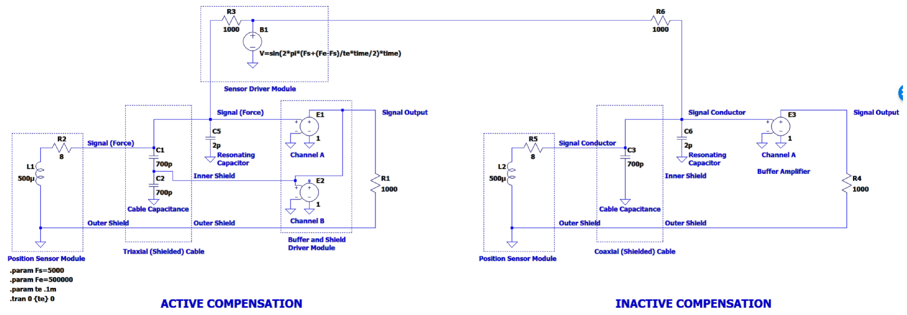
A model of the capacitance compensation system was first simulated using LTSpice to determine performance and stability. The model is shown in Figure 5. Two circuits are simulated simultaneously:
- Active compensation;
- Compensation off.
The results given in Figure 6 compare the active and inactive case. Consistent response over the frequency range is demonstrated by the active compensation circuit. The physical experiments described below verify that the circuit functions as intended.
2.2. Experiment
The cable capacitance technique described above was tested using a custom eddy current sensor. The intended application of this sensor is for continuous position sensing at 750 °C with a 5 kHz bandwidth. A low temperature analog of the high temperature sensor was used to test the active capacitance compensation.
The sensor is wound on a polyoxymethylene (Delrin) spool. The outer diameter is 28 mm and the inside diameter is 17.5 mm. The coil is 100 turns of 34 American Wire Gauge (AWG) enamel coated copper wire. The coil is shown in Figure 7.
To test the active capacitance reduction, the active technique using a triaxial cable was compared to both coaxial and triaxial cable without active compensation. A schematic of the coaxial sensor connection is shown in Figure 8, and the triaxial sensor connection with active capacitance reduction is shown in Figure 9.
The coaxial cable tested was a 7.3 m section of regular RG174/U cable (see Table 1 for dimensions and construction). The triaxial cable tested was a 7.3 m section of Belden 9222 triaxial cable (see Table 2 for dimensions and construction).
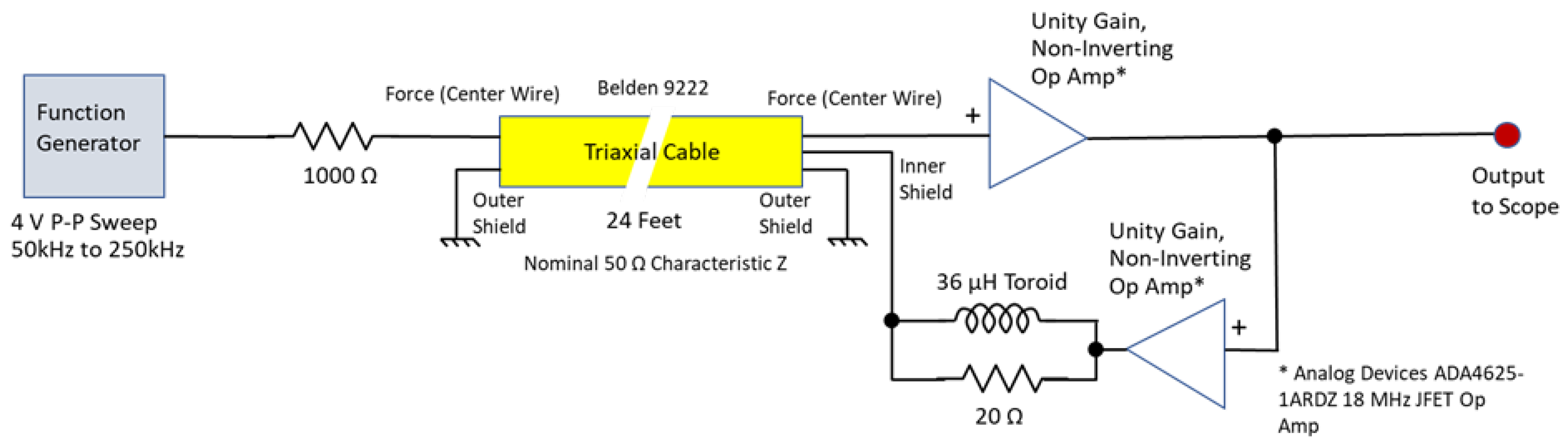
Actual capacitance measurements were taken using a BK Precision model 880 LCR meter. The test circuit used to measure the apparent capacitance reduction is shown in Figure 10.
The circuit shown in Figure 9 shows how the circuit would be used in practice when connected to the sensor shown in Figure 7, where the circuit shown in Figure 10 is the circuit used to measure the reduction in cable capacitance.
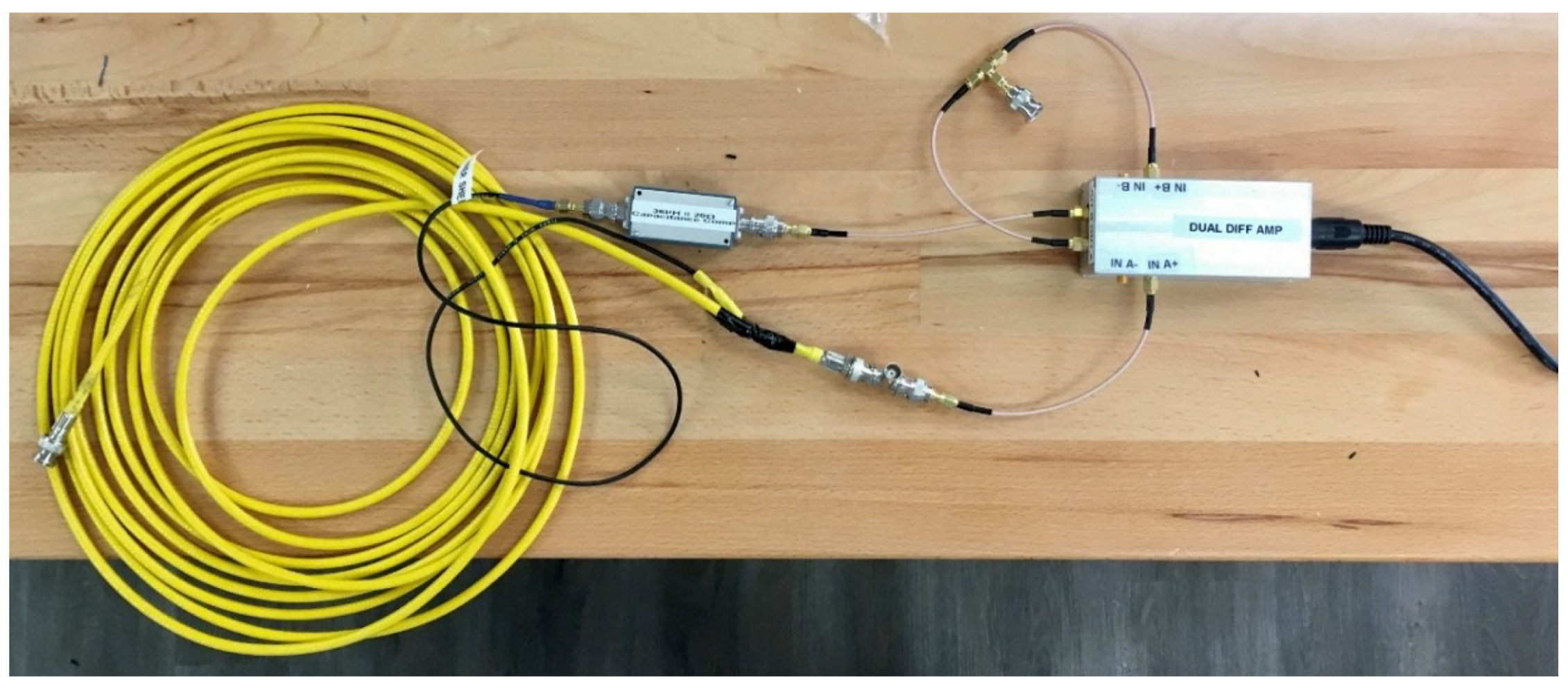
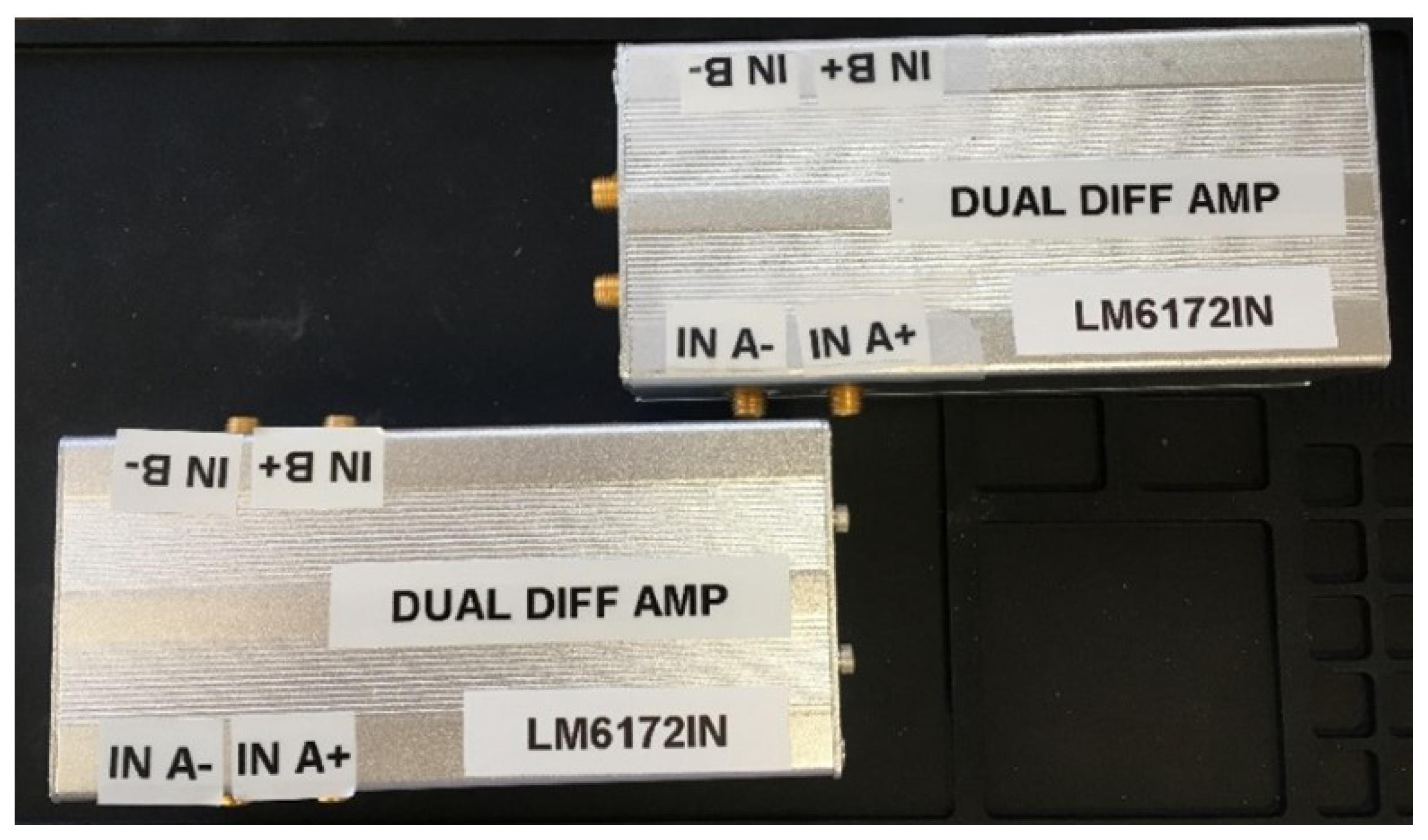
The physical hardware for testing the active capacitance reduction is shown in Figure 11, and the prototype amplifiers are shown in Figure 12.
Note that the Analog Devices ADA4625 operational amplifiers, which were initially selected, did not have sufficient input voltage range to perform well over the sensor’s entire operating regime; therefore, Texas Instruments LM6172-2 dual high-speed operational amplifiers replaced them for the final prototype. The LM6172-2 integrated circuits have exceptionally high slew rate and unity-gain bandwidth (3000 V/µs, 100 MHz).
3. Results
The static capacitance values for the 7.3 m triaxial and coaxial cables are presented in Table 3. These cable capacitance values will decrease the sensor measurement bandwidth and signal-to-noise ratio. Note the exceedingly high capacitance between the inner shield and the outer shield. This high value results from large diameter of the inner shield. As mentioned above, although it does not directly affect the signal path, it presents a difficulty for the op amp driving the shield. A resistor and inductor in parallel are used to stabilize the operational amplifier driving the this large capacitive load.
The static capacitance measurements do not include the buffer amplifier input capacitances, which were about 85 pF. Table 4 shows the result of activating the buffer driven circuit in Figure 10.
The circuit reduces apparent capacitance between center signal conductor and outer shield (which serves as ground shield and signal return path) to about 14 pF. This dynamic reduction represents a 45X improvement. The active capacitance compensation removes all but about 2% of the 627 pF static capacitance of the triaxial cable, while still maintaining a grounded shield for mitigating against the effects of extraneous signals on the measurement by common mode rejection.
4. Discussion
The active cable capacitance reduction technique presented virtually eliminates the apparent cable capacitance as seen by the sensor. This permits high-bandwidth measurements with improved signal-to-noise ratios at the receiving end. While the specific application motivating this work is sensing in extreme environments such as ultra-high temperatures, it has applications beyond extreme environment sensing. For example, it could be used to create high-speed data pipelines for large data centers. It could also be used to create analog sensor networks over large geographical areas.
Author Contributions
R.K. and A.M. conceptualized the presented method. Under supervision and project management by A.M., R.K. and M.R. investigated the presented method. A.M. and R.K. wrote the original draft and M.R. reviewed and edited the document. All authors have read and agreed to the published version of the manuscript.
Funding
The information, data, or work presented herein was funded in part by the Advanced Research Projects Agency-Energy (ARPA-E), U.S. Department of Energy, under Award Number DE-AR0000981. The views and opinions of authors expressed herein do not necessarily state or reflect those of the United States Government or any agency thereof.
Data Availability Statement
No new data were created or analyzed in this study. Data sharing is not applicable to this article.
Conflicts of Interest
The authors declare no conflict of interest.
Abbreviations
The following abbreviations are used in this manuscript:
| ARPA-E | Advanced Research Projects Agency-Energy |
| AWG | American Wire Gauge |
| DOE | Department of Energy |
| MSR | Molten Salt Reactor |
| NASA | National Aeronautical and Space Administration |
References
- Design and Fabrication of High-Temperature Radial Magnetic Bearing for Turbomachinery; Technical Report TM-2003-212300; NASA: Cleveland, OH, USA, 2003.
- Melin, A.M.; Kisner, R.A.; Drira, A.; Reed, F.K. Embedded Sensors and Controls to Improve Component Performance and Reliability—Bench-Scale Testbed Design Report; Technical Report ORNL/TM–2015/584, 1239763; Oak Ridge National Laboratory: Oak Ridge, TN, USA, 2015. [CrossRef]
- Melin, A.M.; Kisner, R.A. Embedded Sensors and Controls to Improve Component Performance and Reliability—Loop-Scale Testbed Design Report; Technical Report ORNL/TM–2016/563, 1338544; Oak Ridge National Laboratory: Oak Ridge, TN, USA, 2016. [CrossRef]
- EIA Standard RS-232-C: Interface between Data Terminal Equipment and Data Communication Equipment Employing Serial Binary Data Interchange; Electronic Industries Associations: Washington, DC, USA, 1969.
- Carlson, B. Maximum transmission distance for RS-232 computer cables. In Proceedings of the Conference Record of 1988 Annual Pulp and Paper Industry Technical Conference, Milwaukee, WI, USA, 6–10 June 1988; IEEE: Milwaukee, WI, USA, 1988; pp. 86–93. [Google Scholar] [CrossRef]
- Beaman, B. High performance mainframe computer cables. In Proceedings of the 1997 Proceedings 47th Electronic Components and Technology Conference, San Jose, CA, USA, 18–21 May 1997; IEEE: San Jose, CA, USA, 1997; pp. 911–917. [Google Scholar] [CrossRef]
- Konovalov, V. Determining the maximum permissible control cable lengths and measures to counteract excessive cable capacitance. In Proceedings of the 2008 International Conference—Modern Technique and Technologies, Tomsk, Russia, 24–28 March 2008; IEEE: Tomsk, Russia, 2008; pp. 32–35. [Google Scholar] [CrossRef]
- Shielded & Coaxial Cable Catalog; National Wire and Cable, Los Angeles, CA, USA. Available online: https://www.nationalwire.com/pdf/cat04_coaxial_cables.pdf (accessed on 15 September 2023).
- Widlar, R. Application Note 241 Working with High Impedance Op Amps; Texas Instruments: Dallas, TX, USA, 1998. Available online: https://www.ti.com/lit/an/snoa664/snoa664.pdf (accessed on 15 September 2023).
- Ultra Low Input Bias Current Instrumentation Amplifier; Burr-Brown: Tuscon, AZ, USA, 1994. Available online: https://www.ti.com/lit/ds/symlink/ina116.pdf (accessed on 15 September 2023).
- Hornak, J.; Trnka, P.; Kadlec, P.; Michal, O.; Mentlík, V.; Šutta, P.; Csányi, G.; Tamus, Z. Magnesium Oxide Nanoparticles: Dielectric Properties, Surface Functionalization and Improvement of Epoxy-Based Composites Insulating Properties. Nanomaterials 2018, 8, 381. [Google Scholar] [CrossRef] [PubMed]
- Haynes, W.M.; Lide, D.R.; Bruno, T.J. (Eds.) CRC Handbook of Chemistry and Physics, 97th ed.; CRC Press: Boca Raton, FL, USA, 2016. [Google Scholar] [CrossRef]
Figure 1.
Typical implementation of a coaxial cable with signal return path through the shield.

Figure 2.
Cross section representation of a coaxial cable.

Figure 3.
Coaxial cable guard circuit with unity gain buffer amplifier.
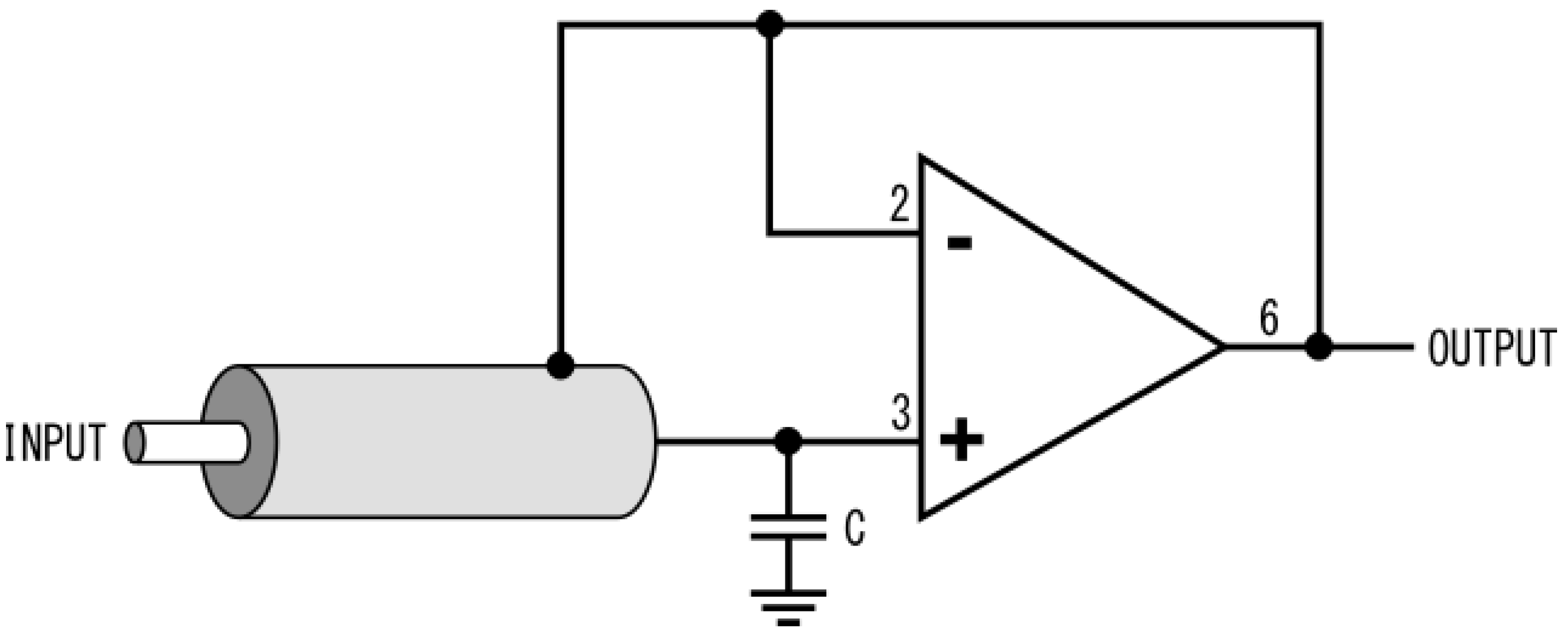
Figure 4.
Cross section representation of a triaxial cable.

Figure 5.
LTSpice simulation of the triaxial driver. The left side is performing the active compensation. The right side is a standard cable.
Figure 5.
LTSpice simulation of the triaxial driver. The left side is performing the active compensation. The right side is a standard cable.

Figure 6.
Frequency sweep plot from 5 kHz to 500 kHz with active (green) and inactive compensation (red).
Figure 6.
Frequency sweep plot from 5 kHz to 500 kHz with active (green) and inactive compensation (red).

Figure 7.
Coil design used for testing the capacitance reduction method.
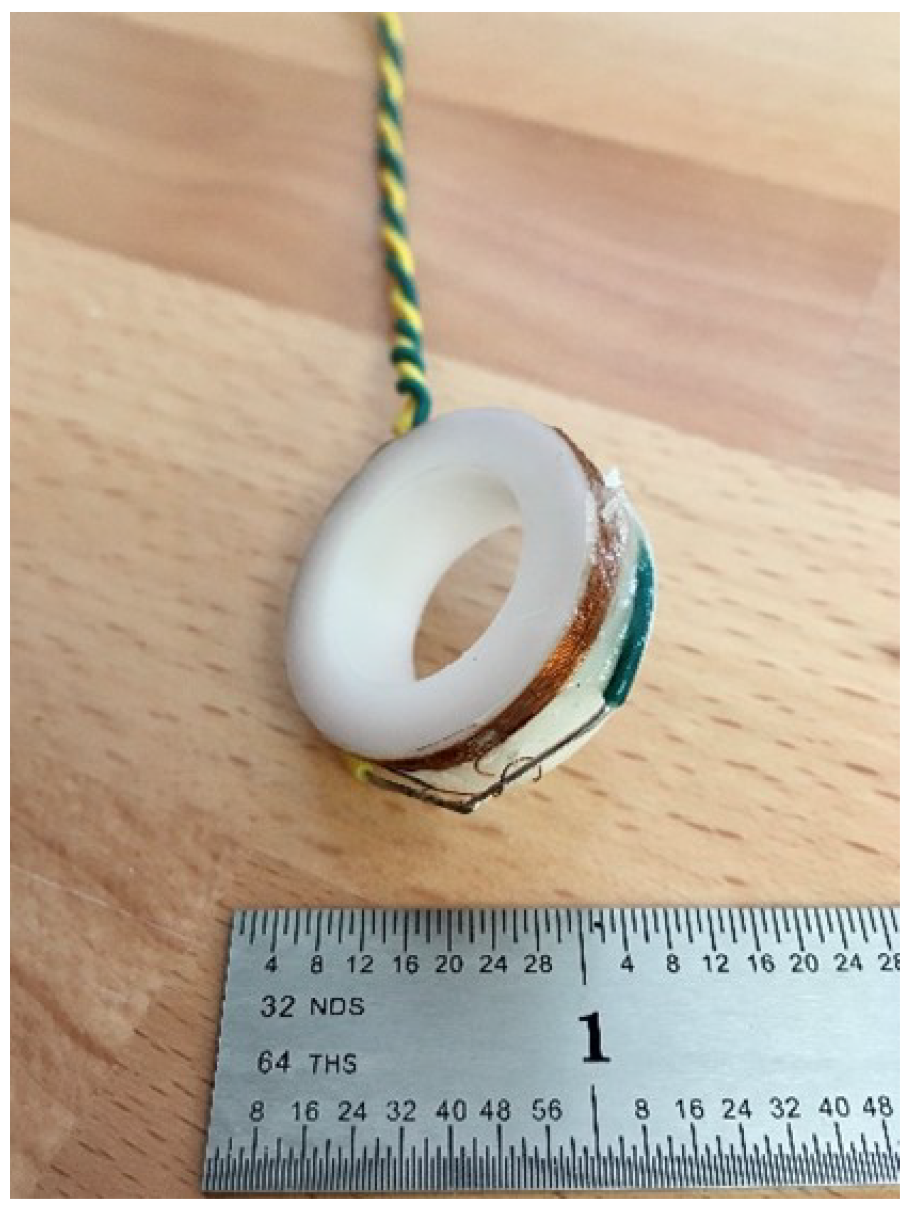
Figure 8.
Coil sensor connection using coaxial cable.

Figure 9.
Coil sensor connection using triaxial cable with active capacitance compensation.
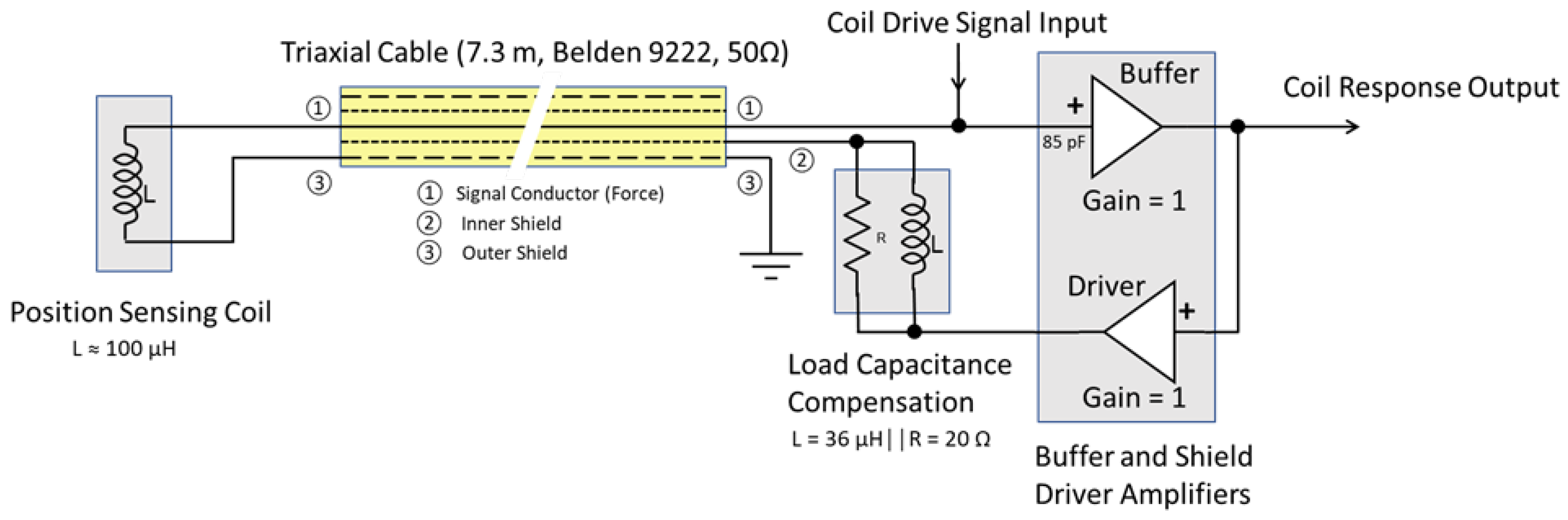
Figure 10.
Active cable capacitance reduction test circuit.

Figure 11.
Physical hardware and 7.3 m of triaxial cable capacitance compensation system shown in Figure 10.
Figure 11.
Physical hardware and 7.3 m of triaxial cable capacitance compensation system shown in Figure 10.

Figure 12.
Active cable capacitance compensation amplifier prototypes.


Table 1.
Construction of a regular RG174/U coaxial cable.
| Layer | Material | Outer Diameter [mm] |
|---|---|---|
| Inner Conductor | Bare Copper Clad Steel | 0.48 |
| Insulation | Polyethylene | 1.52 |
| Shield Layer | Tinned Copper | 1.93 |
| Jacket | Polyvinyl Chloride | 2.80 |
Table 2.
Construction of a Belden 9222 triaxial cable.
| Layer | Material | Outer Diameter [mm] |
|---|---|---|
| Inner Conductor | Tinned Copper | 0.965 |
| Insulation | Polyethylene | 3.05 |
| Inner Shield | Tinned Copper | 3.61 |
| Inner Jacket | Polyethylene | 4.50 |
| Outer Shield | Tinned Copper | 5.05 |
| Outer Jacket | Polyvinyl Chloride | 6.12 |
Table 3.
Static inter-electrode capacitance for triaxial and coaxial shielded cables.
| Measurement Point 1 | Cable Type | Cable Capacitance [pF] |
|---|---|---|
| ➀➁ | Triaxial | 777 |
| ➀➂ | Triaxial | 627 |
| ➁➂ | Triaxial | 3170 |
| ➀➂ | Coaxial | 783 |
Table 4.
Measured cable capacitance as observed by sensor looking into the 7.3 m long Belden 9222 triaxial cable.
Disclaimer/Publisher’s Note: The statements, opinions and data contained in all publications are solely those of the individual author(s) and contributor(s) and not of MDPI and/or the editor(s). MDPI and/or the editor(s) disclaim responsibility for any injury to people or property resulting from any ideas, methods, instructions or products referred to in the content. |
© 2023 by the authors. This manuscript has been authored by UT-Battelle, LLC, under contract DE-AC05-00OR22725 with the US Department of Energy (DOE). The US government retains and the publisher, by accepting the article for publication, acknowledges that the US government retains a nonexclusive, paid-up, irrevocable, worldwide license to publish or reproduce the published form of this manuscript, or allow others to do so, for US government purposes. DOE will provide public access to these results of federally sponsored research in accordance with the DOE Public Access Plan (https://www.energy.gov/doe-public-access-plan). Licensee MDPI, Basel, Switzerland. This article is an open access article distributed under the terms and conditions of the Creative Commons Attribution (CC BY) license (https://creativecommons.org/licenses/by/4.0/).
Share and Cite
MDPI and ACS Style
Melin, A.; Roberts, M.; Kisner, R. Active Reduction of Apparent Cable Capacitance. Sensors 2023, 23, 8319. https://doi.org/10.3390/s23198319
AMA Style
Melin A, Roberts M, Kisner R. Active Reduction of Apparent Cable Capacitance. Sensors. 2023; 23(19):8319. https://doi.org/10.3390/s23198319
Chicago/Turabian StyleMelin, Alexander, Michael Roberts, and Roger Kisner. 2023. "Active Reduction of Apparent Cable Capacitance" Sensors 23, no. 19: 8319. https://doi.org/10.3390/s23198319
Note that from the first issue of 2016, this journal uses article numbers instead of page numbers. See further details here.