A Laboratory Machine Verifying the Operation of a Hydraulic Rope Equalizer with Tensometric Sensors


Department of Machine and Industrial Design, Faculty of Mechanical Engineering, VSB—Technical University of Ostrava, 17. listopadu 2172/15, 708 00 Ostrava, Czech Republic
*
Author to whom correspondence should be addressed.
Sensors 2024, 24(8), 2588; https://doi.org/10.3390/s24082588
Submission received: 22 March 2024
/
Revised: 11 April 2024
/
Accepted: 16 April 2024
/
Published: 18 April 2024
(This article belongs to the Section Physical Sensors)
Abstract
:In mining machines with friction discs, but also in multi-rope traction elevators, it is necessary to distribute the applied tensile load, generated by the weight of the cage and counterweight, evenly in all cross-sections of the load-bearing ropes. Hydraulic devices used for this purpose can operate on the principle of Pascal’s law. This article presents a structural design, a 3D model and an implemented solution of a laboratory device capable of simulating a practical method of evenly distributing the total weight of the load into partial tensile forces of the same size acting on a selected number of load-bearing ropes. The laboratory equipment uses two pairs of three steel cables of finite length for the simulations. During the experimental measurements, tensile forces derived from the tractive force of the piston rods, pushed into the bodies of the hydraulic cylinders by the pressure of the hydraulic oil supplied through the pipeline under the pistons of the hydraulic cylinders, were detected. The resulting amount of hydraulic oil pressure in the hydraulic circuit influenced by different values of the hydraulic oil pressures in the hydraulic cylinders and by the pressure in the supply pipe was experimentally studied on the laboratory equipment. Simulations were also carried out in order to detect the hydraulic oil pressure in the hydraulic circuit caused by the change in the different magnitudes of the tensile forces in the ropes. From the experiments carried out, it follows that with the appropriate choice of hydraulic elements and the design of the hydraulic circuit, the weight of the load, acting as the total pulling force in the ropes, can be evenly distributed (with a deviation of up to 5%) to all cross-sections of the load-bearing ropes. If the exact values of the hydraulic oil volumes under the pistons of all hydraulic cylinders are not known, it is not possible to calculate the pressure values in the hydraulic circuit when the valves of the hydraulic pipes are gradually opened.
1. Introduction
In [1], it is stated that cages, balancing or leveling weights must be suspended on steel ropes. The ropes must meet two requirements: (a) the nominal diameter must be at least 8 mm and (b) the nominal tensile strength of the wires and their parameters must be as specified in EN 123855:2002 [2].
With the entry of the Czech Republic into the EU in 2004, “new” European legislation in the field of testing and placing products on the European market began to apply in the Czech Republic as well. The task of the “New Approach” to European technical legislation is to remove barriers to trade and prevent dangerous products from entering the European market [3].
The European standardization bodies (CEN, CENELEC, ETSI) issue so-called harmonized standards in support of the directives. Compliance with these standards is voluntary. The manufacturer or importer may produce/supply products on the market according to standards other than harmonized standards, but these must be in accordance with the relevant directive. Meeting the requirements of a harmonized standard automatically means that the product is safe and is considered to comply with the directive, which is binding.
The area of steel ropes is not covered by a single document but rather falls under several directives depending on the use of the rope: (a) elevators, (b) machinery, (c) passenger cable cars and lifts or (d) mining traction machines. For each of the aforementioned areas, different requirements (combinations of modules) for conformity assessment and product certification apply in accordance with the relevant directives and the Act on Technical Requirements for Products (No. 22/1997 Coll.).
Conformity assessment procedures according to Act 22/1997 Coll. [4] represent the minimum requirements according to which the conformity assessment and certification of the product should be carried out; in the case of an elevator, it is a combination of modules B + C.
Module B: The assessment of the conformity of a product type sample (prototype) by an authorized person and issuance of a certificate by an authorized person (product type certification): (a) the manufacturer or importer provides the authorized person with technical documentation and a representative sample of the product type; (b) the authorized person performs tests to see if the product type sample meets the requirements of technical regulations and issues an EC type approval certificate (product type certificate).
Module C: The assessment of the conformity of the product with the certified product type: the manufacturer, importer and authorized person proceed according to module B and additionally, (a) the manufacturer or importer issues a declaration of conformity, (b) the importer takes all measures to ensure the conformity of the product properties with the certified type and (c) the authorized person performs the testing of product properties at random intervals for the purpose of verifying conformity, as stipulated by the relevant technical regulation.
From the above, it follows that steel ropes require different levels of conformity assessment and product certification depending on the method of use. In terms of the “new” European legislation, the minimum is to submit technical documentation and a representative sample of the product to an authorized person who will perform tests and issue an EC type approval certificate. The manufacturer or importer then issues a declaration of conformity (certificate) upon the delivery of the product. This procedure applies to ropes in elevators.
Chapter “1.3 Suspension and support devices” of “Appendix No. 1 to Government Regulation No. 122/2016 Coll.” [4] states the following: Suspension or support devices of the elevator cage, its fastening and connecting parts must be selected and designed so as to ensure the necessary level of safety and minimize the risk of the cage falling, taking into account the conditions of use, the materials used and the manufacturing conditions. Where ropes or chains are used to suspend the cage, a minimum of two separate ropes or chains, each with a separate fastening, must be used. These ropes and chains shall not have any joints or entanglements unless necessary for fastening or to form loops.
Given that compliance with harmonized standards is voluntary, it is possible to use ropes with diameters smaller than dr = 8 mm in traction elevators intended for the transport of persons, or persons and cargo, according to [5], if compliance is assessed according to [4,5].
According to [1], the load capacity of traction elevators [6,7,8], which are adapted to transport people, is assigned the largest usable area of the cage, in order to prevent the overloading of the cage with the number of transported persons. For high load capacities (over 2500 kg) of traction elevators, 0.16 m2 of area is added (to an area of 5 m2) for every 100 kg increase in weight.
According to Relation (1), it is possible to determine the required number of load-bearing ropes, nr [−], if Q [kg]—elevator capacity, K [kg]—cage weight, it—rope transmission [−], kr [−] rope safety and Fmin [N]—minimum breaking force at rope tensile strength S [N·mm−2]—are known. The large number of load-bearing ropes results from the necessity of choosing smaller rope diameters, as these diameters determine the minimum diameters of the friction discs (40 times) and rope pulleys.
According to Relation (1), it can be observed that (for the chosen design of the nominal diameter wire rope dr [m], which is assigned according to [2] the minimum breaking force Fmin [N] of the rope at the rope grade S [N · m−2]) the number of load-bearing ropes of the elevator nr [−] is directly proportional to the lifting capacity Q [kg]. With high lifting capacities Q [kg], it is necessary to hang the cage on a large number of ropes [9,10] in traction elevators; see Figure 1.
However, an increasing number of the cross-sections of carrier ropes leads to a possible situation, when the loading exerted by the weight of the cage and the weight of the counterweight is not evenly distributed into the individual cross-sections of the carrier ropes. This different loading of the individual carrier ropes leads to an uneven wear of the friction disc grooves and different wear of the individual carrier ropes.
The equalization of tensile forces in the cross-sections of the steel ropes of traction elevators is based on a mechanical [11,12,13,14] or hydraulic [15,16] principle.
Foreign scholars have conducted a lot of work on monitoring the wire rope tension and load. In foreign countries, the wire rope tension and load measurement method measured by the sensor or other instruments have been developed in many countries [17,18,19].
In 2012, Jin and Zhang [20] designed a tension sensor for the hoist wire rope using the strain gauge as the measurement principle and the spoke as the flexible structure and adopted configuration software as detection system software to realize the online monitoring of the tension.
G. Lei et al. in the article [21] state that due to the longitudinal and lateral coupling vibration of wire ropes during the operation of the hoist, there are high-frequency components in measured tension signals of wire ropes, which cannot effectively characterize the actual lifting load. To overcome this problem, a particle damping sensor with a vibration dissipation function is designed.
L. Hrabovský in [22] presents the construction design, 3D model and produced device of one of four produced prototypes, which were constructed in the “Research and Testing Laboratory” and allow for the setting of differing values of tension forces in the system of the ropes of a traction elevator to values of the same size.
In the study [23], M. Yao et al. designed the structure of a nondestructive pressure-type parachute rope tension sensor and set the location of the strain gauge patch using the ANSYS Version 12.0 simulation software to obtain a high sensor sensitivity.
In the article [24], similar to [23], a new type of tension sensor is presented according to the needs of measuring the tension of varieties of ropes such as ropes in parachutes. The sensor is designed to have a T-shape structure, so that the rope can cross over the sensor without any damage during measurement.
A measurement method of wire rope tension by transferring wire rope tension measurement to pressure measurement, which improves the measurement safety and avoids the safety hazards of adopting a pull sensor in series with a wire rope, is presented in article [25] by authors G. Xu et al.
The paper [26] describes the structural design of a laboratory device that allows for presenting the operation, simulating work procedures and checking the functionality of the elevator “rope sensors” when equalizing different tensile forces in partial ropes of a rope system of traction elevators. The laboratory device is modified for checking operations of commonly used rope sensors.
The results in the article [27] show that the authors G. Lei et al. proposed compensation improves the accuracy of the real-time measurement system of wire rope tension. Articles [28,29] state that oil pressure sensors are installed on the hydraulic connection device to monitor the tension of wire ropes. The change in acceleration during the operation process of the hoist causes the tension change in each wire rope. It leads to impact on the cylinder of the hydraulic connection device, enlarges the pressure loss and makes the non-linear friction become more complex, which affects the monitoring accuracy.
In order to solve the problem about the tension detection of the multi-hoisting wire rope, the paper [30] designs a dynamic tension detection system of the multi-hoisting wire rope. The system can real-time detect the tension of the rope, alarm to overload, imbalance and other security hazards during the operation and guarantee the safe operation of the elevator. This paper designs a tension sensor for the hoist wire rope.
To improve the accuracy of the tension measurement of bridge wire ropes, research on a magnetic flux sensor based on the magneto-elastic effect and its application in measuring the tension of bridge wire ropes is presented in [31]. A device composed of a magnetic flux sensor and other signal processing circuits is designed, and it can be used to measure the tension on the wire ropes precisely and enduringly by testing the magnetic flux through the sensor without causing damage on wire ropes.
The article [32] contains mathematical formulas that are used for calculations of the necessary adjustment of friction pulley radii aimed at equalizing forces in the individual ropes of the hoisting system.
2. Materials and Methods
The structural design of the laboratory equipment intended for the presentation and simulation of setting the same magnitudes of tensile forces in three cross-sections (nr = 3, see Figure 1) of steel ropes was created in the environment of SolidWorks® Premium SP 5.0, see Figure 2, at the Department of Machine and Industrial Design, Faculty of Mechanical Engineering, VSB-Technical University of Ostrava.
The laboratory equipment, which allows for setting the same amount of tensile force in the individual cross-sections of the ropes by means of hydraulic oil pressure, consists of a welded (from closed profiles of a square 40 mm × 40 mm cross-section with a wall thickness of 1.5 mm) steel structure 1; see Figure 3a. The hydraulic oil (max. pressure 300 bar = 30 MPa) is distributed by the manual hydraulic pump 5 [33] with a tank of 3 dm3 through the designed pipeline of the hydraulic circuit 6 (see Figure 3b) to the double-acting hydraulic cylinders 3 [34].
It is possible to supply hydraulic oil with a working pressure pp = 180 bar = 18 MPa (maximum pressure pmax = 250 bar = 25 MPa) to hydraulic cylinders 3 [34] (inner diameter dc = 32 mm, piston rod diameter dp = 20 mm, piston rod stroke hhp = 50 mm). The maximum pressure force FRp [N] and the pulling force FR [N] that can be derived from the hydraulic cylinder 3 with the calculated cross-section Sc [m2] and Shc [m2], see (2), is given by Relation (3). The cross-section of the hydraulic cylinder in the space above the piston is expressed as Sc [m2], and the cross-section of the hydraulic cylinder in the space below the cylinder piston is Shc [m2].
On one side, the ends of the steel ropes 2 with a diameter dr = 4 mm of construction 6 × 19M—WSC [35,36] are attached to the piston rods of the hydraulic cylinders 3. The other ends of the steel ropes 2 are attached to the tensometric force sensors 4 [37] with a measuring range of 0 ÷ 2450 N.
Assuming that valves A, B and C supplying/extracting hydraulic oil to the space under the pistons of the hydraulic cylinders 3(i) are closed, see Figure 4a, where i (=1 ÷ 3) is the number of load-bearing ropes, and assuming the forces FRi [N] in the ropes differ, a hydraulic oil pressure of different magnitudes ppi [Pa] is generated in the space under the pistons of individual hydraulic cylinders 3(i); see (4).
To equalize the different pressures ppi [Pa] of the hydraulic oil in the spaces under the hydraulic cylinder pistons 3(i) to the same pressure value ppr [Pa], see Figure 4b, it is necessary to close valve D of the hydraulic circuit first. In individual hydraulic cylinders 3(i) with hydraulic oil pressure ppi [Pa], there is a certain volume of hydraulic oil Vi [m3] in the space under the pistons, and in the hydraulic pipe with hydraulic oil pressure pp [Pa], there is a volume of hydraulic oil Vp [m3]. The maximum possible volume VM [m3] of hydraulic oil in the space under the piston of the hydraulic cylinder 3(i) (at the maximum displacement of the piston rod hhp [mm] from the body of the hydraulic cylinder) can be expressed according to Relation (5).
After closing valve D of the laboratory equipment and gradually opening valves A, B and C, the relative pressures ppi [Pa] of the hydraulic oil under the pistons of the hydraulic cylinders 3(i) stabilize at the same value ppr [Pa] (6).
The implemented laboratory equipment, which was built in the Laboratory of Research and Testing, Department of Machine and Industrial Design, Faculty of Mechanical Engineering, VSB-Technical University of Ostrava, is presented in Figure 5.
A system (the so-called measurement chain) created from a sequence of devices and other instruments connected in a way which makes it possible to process the measurement signal from the input measured quantity up to obtaining the output value is shown in Figure 6. The plugs of the “D-sub DE-9” connectors 2, which terminate the wires of the three tensometric force sensors 1 [37], are inserted into the sockets of the DS NET BR4 module 3 [37]. The DS GATE 4 [38] module is connected to the PC (ASUS K72JR-TY131 (Taipei, Taiwan)) 6, on which the DEWESoft X2 SP5 7 (Gabrsko, Slovenia) [39] software is installed, through the RJ45 connectors 5 of the network cable.
3. Results
Experimental measurements performed on laboratory equipment, see Figure 5, were carried out in several independent experiments.
The free ends of three steel ropes 1 of finite length were attached to the upper part, see Figure 7a, of the steel frame of the laboratory equipment.
In the second variant, the ends of three double-length steel ropes were attached to the lower part, see Figure 8b, of the steel frame of the laboratory equipment.
In both cases, the attachment of the ends of the ropes (to the upper part Figure 7a or to the lower part Figure 8b of the laboratory equipment) exerts the same amount of pulling force on the steel rope assuming an identical insertion of the piston rod into the body of the hydraulic cylinder, i.e., at the same hydraulic oil pressure under the hydraulic cylinder piston.
3.1. The Magnitude of the Resulting Hydraulic Oil Pressure Is Affected by the Different Values of the Hydraulic Oil Pressures in the Hydraulic Cylinders and the Pressure in the Supply Pipe
The measurements were carried out under the same technical conditions. Tensometric force sensors 4 (Figure 3) were calibrated with a load of known weight before the experimental tests were performed on the laboratory equipment (Figure 5). At the beginning of the measurements, the piston rods were fully extended from the bodies of all hydraulic cylinders 3, whereby the tensometric force sensors 4 were loaded only by the weight of the freely suspended ropes 2. In Figure 9, this state is designated as (a).
The hydraulic oil was supplied under a pressure of pp1 [Pa] by the manual hydraulic pump lever, with valves D and A open (see Figure 4) and valves B and C closed, under the hydraulic cylinder piston 3(1). The pressure pp1 [Pa] of the hydraulic oil acting on the piston of the hydraulic cylinder 3(1) pushed the piston rod into the body of the hydraulic cylinder 3(1), thereby generating a pulling force FR1 [N] of a certain magnitude in the steel rope 2, which was detected by the tensometric force sensor 4. In Figure 9, this state is designated as (b).
After valve A was closed (with valve D open and valves B and C closed), valve B was opened and hydraulic oil was fed into the space under the piston of the hydraulic cylinder 3(2) under a pressure of pp2 ≠ pp1 [Pa], then valve B was closed. The pulling force FR2 [N] in the steel rope 2 detected by the tensometric force sensor 4 is directly proportional to the size of the applied pressure pp2 [Pa] of the hydraulic oil under the piston of the hydraulic cylinder 3(2). In Figure 9, this state is designated as (c).
With valve D and C open (and valves A and B closed), hydraulic oil was pumped under pressure pp3 ≠ pp2 ≠ pp1 [Pa] into the space under the hydraulic cylinder piston 3(3). When the pressure pp3 [Pa] was reached in the space under the piston of the hydraulic cylinder 3(3), valves C and D were simultaneously closed. The pulling force FR3 [N] in the steel rope 2 detected by the tensometric force sensor 4 is directly proportional to the magnitude of the supplied pressure pp3 [Pa] of hydraulic oil under the hydraulic cylinder piston 3(3). In Figure 9, this state is designated as (d).
When valves A, B, C and D are closed, hydraulic oil pressure pp = pp3 [Pa] is present in the supply pipe.
With valve D closed and hydraulic oil pressure in the supply pipe of the hydraulic circuit pp [Pa], valves A, B and C were gradually opened. Valve A was opened first. The different pressure values pp1 [Pa] and pp = pp3 [Pa] (with valves B, C and D closed) stabilized at the same pressure of pp1p [Pa]. The magnitude of the pressure pp1p [Pa] is dependent on whether the pressure pp1 [Pa] is less or greater than the pressure pp [Pa] and also on the volumes V1 [m3] and Vp [m3]. During experimental measurements, it was not possible to accurately measure the volumes of hydraulic oil in the spaces above the piston Vi [m3] for all hydraulic cylinders nor the volume Vp [N] of hydraulic oil in the pipes.
Assuming that the volume of hydraulic oil under the piston V1 [m3] of the hydraulic cylinder 3(1) is the same as the amount of hydraulic oil in the pipe Vp [m3] of the laboratory equipment, then the resulting pressure is pp1p = 0.5· (pp1 + pp) [Pa]. If the volume of hydraulic oil under the piston of the hydraulic cylinder V1 [m3] is greater, less or equal to the volume of hydraulic oil in the hydraulic pipe Vp [m3] and if pressure pp1 = pp [Pa], then the resulting pressure is pp1p = pp1 [Pa].
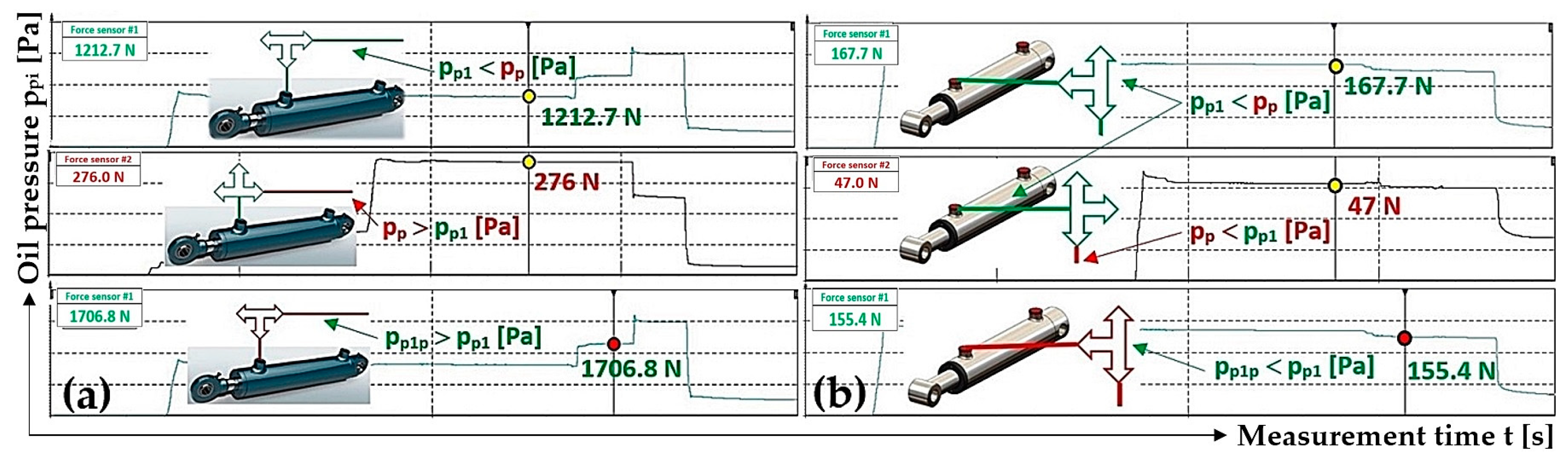
The magnitude of the resulting pressure pp1p [Pa] is greater than pp1 [Pa] if pp > pp1 [Pa]; see Figure 10a. The magnitude of the pressure pp1p [Pa] is less than pp1 [Pa] if pp < pp1 [Pa]; see Figure 10b.
In the next steps, first valve B and then valve C were opened (while valve D was closed). The pressures in the spaces above the pistons in all three hydraulic cylinders (when valves A, B and C are open) as well as the pressure in the supply pipe of the hydraulic circuit (when valve D is closed) stabilize at the same pressure ppr [Pa], the theoretical magnitude of which can be described by Relation (6). In Figure 9, this state is designated as (e).
After valve D is opened, the hydraulic oil moves to the tank of the manual hydraulic pump, so that the pressure of the hydraulic oil in the supply pipe of the hydraulic circuit and in the space under the pistons of all hydraulic cylinders is zero (takes on the value of hydrostatic pressure). In Figure 9, this condition is designated as (f).
Table 1 presents different initial values of pulling forces FRi [N] in ropes 2, measured using tensometric force sensors 4, see Figure 3, which were generated by the pressure of the oil supplied by the hydraulic pump into the space under the pistons of the hydraulic cylinders 3(i). The measured pulling forces FRi [N] in ropes 2, during the gradual filling (first cylinder 3(1) and last cylinder 3(3)) of hydraulic oil into the space under the pistons of hydraulic cylinders 3(i) of the laboratory equipment, were used to calculate the pressures ppi [Pa] of hydraulic oil under the piston of the hydraulic cylinder 3(i).
The calculated pressures ppi [Pa] were verified with the measured (using manometers; see Figure 11) hydraulic oil pressures under the pistons of hydraulic cylinders 3(i). The manometer detected pressures in the unit of bar = 1·105 Pa (0.1 MPa).
Figure 11.
(a,b) Hydraulic circuit of laboratory equipment and (c) manual hydraulic pump. 1—manometer; 2—double-acting hydraulic cylinder; 3—manual hydraulic pump.
Figure 11.
(a,b) Hydraulic circuit of laboratory equipment and (c) manual hydraulic pump. 1—manometer; 2—double-acting hydraulic cylinder; 3—manual hydraulic pump.


Table 1.
The pulling force in the rope and the pressure of the hydraulic oil in the space under the hydraulic cylinder piston and in the supply pipe.
Table 1.
The pulling force in the rope and the pressure of the hydraulic oil in the space under the hydraulic cylinder piston and in the supply pipe.
| n | FR1 | FR2 | FR3 | pp1 | pp2 | pp3 = pp |
|---|---|---|---|---|---|---|
| [N] | [106·Pa] | |||||
| 1 | 786.9 1 | 1170.2 1 | 2090.4 1 | 1.61 2 | 2.39 2 | 4.27 2 |
| 2 | 1158.7 | 531.9 | 2127.8 | 2.36 3 | 1.09 3 | 4.34 3 |
| 3 | 696.1 | 1170.2 | 2203.5 | 1.42 | 2.39 | 4.50 |
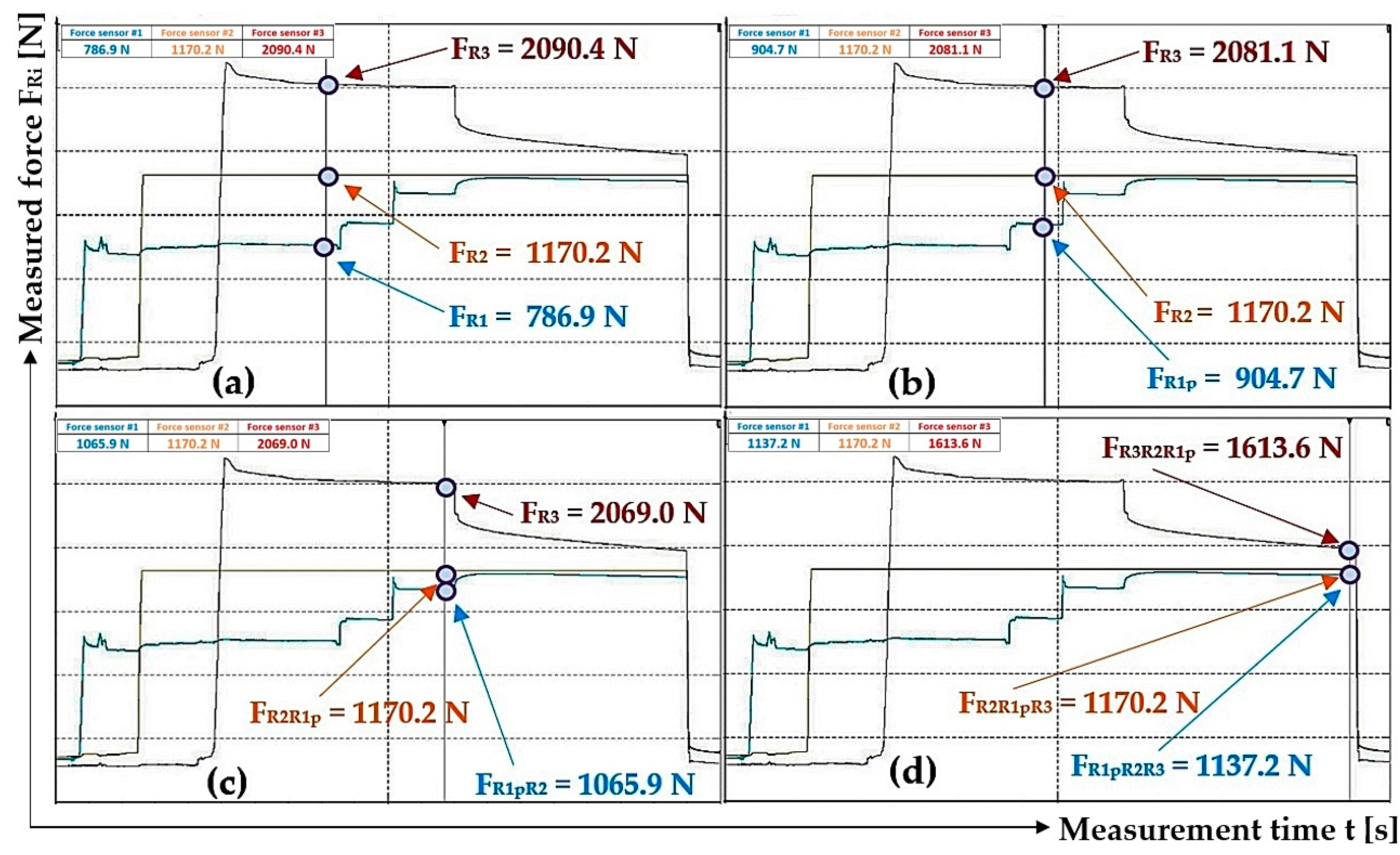
Figure 12a presents the values of the measured pulling forces, which were generated by the pressure of the hydraulic oil supplied under the pistons of the hydraulic cylinders during the gradual opening and closing of valves A, B and C while valve D is open; see Figure 4.
Figure 12b shows the value of the detected force FR1p [N] (in the rope above the hydraulic cylinder 3(1)) which was measured by the tensometric force sensor (with valves B, C and D closed) at the moment when valve A was opened. At this moment, the pressure pp1 [Pa] of the hydraulic oil under the piston of the hydraulic cylinder 3(1) equalized with the pressure of the hydraulic oil in the pipe pp [Pa] to the value of pp1p [Pa], and the pulling force FR1p was acting in the rope above the cylinder 3(1) [N].
Table 2 lists the values of the forces detected in the ropes 2 by the tensometric force sensors 4 at the moment when valves A, B and C were gradually opened while valve D was left closed.
Table 2.
The pulling force in the ropes during the gradual opening of valves A, B and C supplying hydraulic oil to the space under the pistons of the hydraulic cylinders.
Table 2.
The pulling force in the ropes during the gradual opening of valves A, B and C supplying hydraulic oil to the space under the pistons of the hydraulic cylinders.
| n | FR1p | FR1pR2 | FR2R1p | FR1pR2R3 | FR2R1pR3 | FR3R2R1p | pp3p2p1p = ppr |
|---|---|---|---|---|---|---|---|
| [N] | [106·Pa] | ||||||
| 1 | 904.7 1 | 1065.9 2 | 1170.2 2 | 1137.2 3 | 1170.2 3 | 1613.6 3 | 3.29 |
| 2 | 1158.7 | 1158.7 | 806.1 | 1158.7 | 1009.4 | 1404.1 | 2.86 |
| 3 | 878.9 | 1170.2 | 2175.5 | 1052.5 | 1170.2 | 1623.7 | 3.31 |
Figure 12c shows the values of the detected forces FR1pR2 [N] (in the rope above the hydraulic cylinder 3(1)) and FR2R1p [N] (in the rope above the hydraulic cylinder 3(2)), which were measured by the tensometric force sensors when valve B was opened (with valves C and D closed and valve A open). At this moment, the pressure pp2 [Pa] of the hydraulic oil under the piston of the hydraulic cylinder 3(2) equalized with the pressure of the hydraulic oil in the pipe pp1p [Pa] (as well as in the space under the piston of the hydraulic cylinder 3(1)) to the value pp2p1p [Pa] and pulling forces FR1pR2 [N] (in the rope above the hydraulic cylinder 3(1)) and FR2R1p [N] (in the rope above the hydraulic cylinder 3(2)) were measured in the ropes.
Figure 12d shows the values of the detected forces in the ropes above the hydraulic cylinders 3(i) that were measured by the tensometric force sensors at the moment when valve C was opened (with valve D closed and valves A and B open). At this moment, the pressure pp3 [Pa] of the hydraulic oil under the piston of the hydraulic cylinder 3(3) equalized with the pressure of the hydraulic oil in the pipe pp2p1p [Pa] to the value pp3p2p1p [Pa], and pulling forces FR1pR2R3 [N] (in the rope above hydraulic cylinder 3(1)), FR2R1pR3 [N] (in the rope above hydraulic cylinder 3(2)) and FR3R1pR2 [N] (in the rope above hydraulic cylinder 3(3)) were measured in the ropes.
By analyzing the individual phases of the measurements, see Figure 12b–d and Table 2, on the laboratory device (see Figure 5), it can be observed that when valves A to C are gradually opened, the measured pulling forces in the ropes are not completely equalized. The pressure pp1 [Pa] (pulling force FR1 [N]), when opening valve A, should equalize to the same magnitude as the hydraulic oil pressure in the hydraulic pipe. The magnitude of pressure pp1p [Pa] depends on the magnitudes of the volumes V1 [m3] and Vp [m3] and the magnitudes of the initial pressures pp1 [Pa] and pp [Pa]. According to Relation (7), it is possible to calculate the theoretical pressure pp1p [Pa] under the piston of the hydraulic cylinder and the pressure in the pipe when valve A is open (and valves B, C and D are closed).
The volume of hydraulic oil in the hydraulic pipe Vp [m3] is constant and does not change in the laboratory equipment during all experimental measurements. The volumes Vi [m3] of hydraulic oil under the pistons of the hydraulic cylinders are different for each measurement performed. Their values depend on the magnitude of the supplied hydraulic oil pressure under the piston of the respective hydraulic cylinder (3; see Figure 3), i.e., on how far the piston rod is inserted into the hydraulic cylinder body. Due to the different and unknown volumes Vi [m3], Relation (7) does not allow for the calculation of the theoretical magnitude of the hydraulic oil pressures in the hydraulic circuit pipeline when opening valves A and B without the knowledge of the volumes Vi [m3].
3.2. The Magnitude of the Resulting Pressure of the Hydraulic Oil Affected by the Change in the Different Magnitudes of the Pulling Forces in the Ropes
The hydraulic pump (Figure 11c) was used to supply hydraulic oil with a pressure of pp [Pa] through the hydraulic pipe (when valves A, B and C of all three hydraulic cylinders 3(i) are open; see Figure 4) into the space under the pistons of hydraulic cylinders 3(i). The pressure of the hydraulic oil ppi [Pa] under the pistons of the hydraulic cylinders 3(i) caused the piston rods to be inserted into the bodies of the hydraulic cylinders 3(i) and generated the pulling forces in ropes FRi [N], whose magnitudes were detected by the tensometric force sensors 4 (Figure 3) [37]. After valve D was closed, the pressure of the hydraulic oil in the hydraulic pipe and the pressure under the pistons of the hydraulic cylinders 3(i) was pp [Pa], which can be expressed according to Relation (4), provided that the values of forces FRi [N], which were detected by tensometric force sensors, are known.
When valves A, B and C of the hydraulic cylinders 3(i) are closed (provided that valve D is closed) and the screws that mechanically attach the suspension nuts of the tensometric force sensors 4 (Figure 3) to the steel frame of the laboratory equipment 1 are gradually tightened, the pulling forces FRi [N] in the ropes 2 differed. The maximum pulling force FDs [N], which could be generated in the ropes 2, is given by the permissible load mDs = 250 kg (FDs = 2.45 kN) of the tensometric force sensor 4.
The magnitudes of pulling forces FRi [N] measured by tensometric force sensors 1, see Figure 6, were recorded by modules 3 and 4 of the DEWESoft DS-NET measuring apparatus and displayed on the PC monitor 6 in the environment of DEWESoft® X2 SP5 7; see Table 3.
From the measured pulling forces FRi [N], the pressures ppi [Pa] in the hydraulic cylinders 3(i) were calculated according to Relation (4) (using the known cross-section Shc [m2] of the hydraulic cylinder surface).
When valve A of the hydraulic cylinder 3(1) is opened (and when valves B, C and D are closed), the pressure pp1 [Pa] of the hydraulic oil under the piston of the hydraulic cylinder 3(1) (at volume V1 [m3]) and the pressure pp [Pa] of the hydraulic oil in the supply pipe (at volume Vp [m3]) of the hydraulic circuit equalized to the pressure value pp1p [Pa]; see Figure 13.
The pressure of the hydraulic oil pi [Pa] in the spaces under the pistons of the hydraulic cylinders 3(i) generates pulling forces FRi [N] in the i-th steel rope, and their magnitudes are detected by tensometric force sensors 4 (see Figure 3). The hydraulic oil pressures pi [Pa], as recorded in Table 4, were calculated from the recorded values of pulling forces FRi [N] according to Relation (4).
Table 4.
The pulling force in the rope and the pressure of the hydraulic oil in the space under the hydraulic cylinder piston and in the supply pipe.
Table 4.
The pulling force in the rope and the pressure of the hydraulic oil in the space under the hydraulic cylinder piston and in the supply pipe.
| n | Fp1 | Fp2 | Fp3 | FR1 | FR2 | FR3 | pp | pp1 | pp2 | pp3 |
|---|---|---|---|---|---|---|---|---|---|---|
| [N] | [MPa] | |||||||||
| 1 | 285.9 1 | 318.6 1 | 297.2 1 | 642.3 2 | 1170.2 2 | 1921.5 2 | 0.58 | 1.31 | 2.39 | 3.92 |
| 2 | 606.3 | 615.6 | 618.0 | 1034.5 | 1170.2 | 1677.8 | 2.24 | 1.26 | 2.39 | 3.42 |
| 3 | 534.5 | 556.5 | 503.4 | 1104.0 | 1170.2 | 1816.4 | 1.09 | 2.25 | 2.39 | 3.71 |
Figure 14.
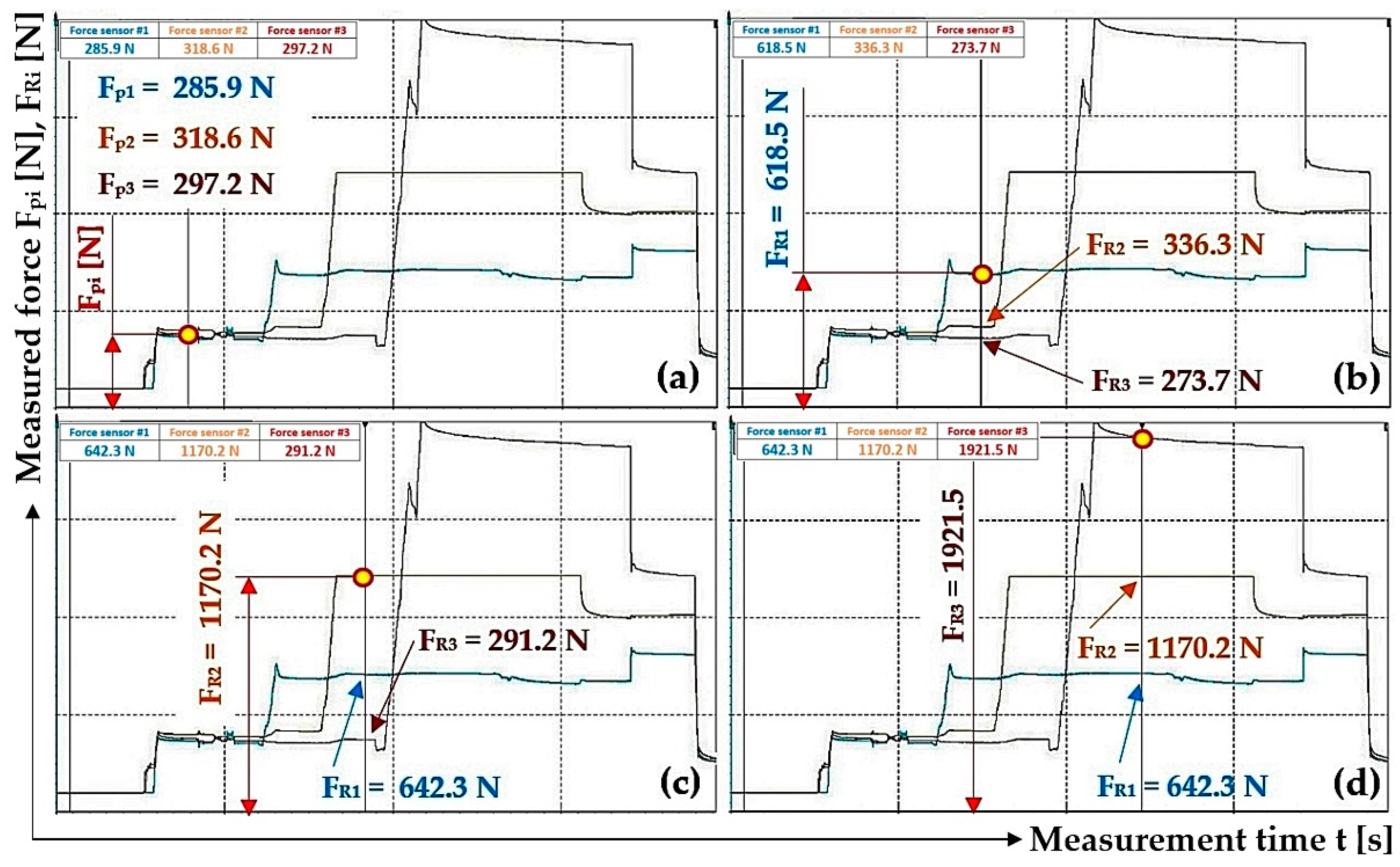
Detected pulling forces in the ropes, generated by applying hydraulic oil pressure under the hydraulic cylinder pistons: (a) valves A to D open; (b) valves A and D open, valves B and C closed; (c) valves B and D open, valves A and C closed and (d) valves C and D open, valves A and B closed.
Figure 14.
Detected pulling forces in the ropes, generated by applying hydraulic oil pressure under the hydraulic cylinder pistons: (a) valves A to D open; (b) valves A and D open, valves B and C closed; (c) valves B and D open, valves A and C closed and (d) valves C and D open, valves A and B closed.

By analyzing Figure 15a–c, it can be observed that when valves A, B and C are gradually opened, the pulling forces (detected by tensometric force sensors [36]) acting in the ropes, as well as the hydraulic oil pressures in the spaces under the pistons of the hydraulic cylinders, did not equalize to the same value. The pulling forces in all three ropes equalized to approximately the same value only after valve D was opened; see Figure 15d.
The different values of pulling forces, see Figure 16c, can be explained by the fact that the spaces above the pistons of the hydraulic cylinders are interconnected by a closed and sealed hydraulic pipe. When the piston rods are inserted into the hydraulic cylinders, the contact surfaces of the seals (polyurethane) of the pistons with the inner surface of the hydraulic cylinders create friction between these contact surfaces, which acts as a resistance force when the piston rods are inserted into the hydraulic cylinders.
4. Discussion
The implemented laboratory equipment, as described in this article, can be used in practice for the continuous equalization of pulling forces in elevator ropes but especially in mining machines with friction discs, where winding ropes of significantly longer lengths than the load-bearing ropes of elevators are used. The advantage of the presented laboratory equipment is that it can gradually reduce the pulling force in one rope if it is larger than the pulling forces in the neighboring ropes of the multi-rope system.
Brugg’s Rope Load Equalizer (RLE) [14] is a hydraulic device that uses hydraulic fluid pumped through an interconnected system of hoses into hydraulic cylinders to create a tensile force of the same magnitude in all elevator rope fastening sockets. This device is installed on a specific traction elevator by an authorized person only when it is required to set or verify that the load from the weight of the cage or counterweight is evenly distributed over the designed number of load-bearing ropes.
Mechanical devices [11,12,22] are also installed, similarly to device [14], on a particular traction elevator when it is required to set or verify that the load from the weight of the cage or counterweight is evenly distributed over the designed number of load-bearing ropes.
Figure 12d shows the measured values of pulling forces that were detected by tensometric force sensors with valves A to C open and valve D closed in the laboratory device (Figure 4). This condition (valves A to C open, valve D closed) describes the case when the hydraulic oil pressure is the same in the spaces under the pistons of all hydraulic cylinders as well as in the hydraulic pipeline. With the same amount of pressure (valves A to C open), the same pulling force should act in all three ropes. However, the measured values of pulling forces in individual ropes are not completely identical. The highest measured value of a pulling force is 1613.6 N and the lowest is 1137.2 N; see Table 2. The highest measured value of a pulling force is 41.9% higher than the lowest measured value.
The reason for the difference in the pulling forces, which were detected by tensometric force sensors (see Figure 12d) and which act in the individual ropes when valves A to C are open, was attributed to the increasing hydraulic oil pressure in the spaces above the pistons of the individual hydraulic cylinders when the piston rods were inserted into the bodies of the hydraulic cylinders by the pressure of the hydraulic oil ppi [Pa] supplied under the pistons of the hydraulic cylinders. It was assumed that the pressure of the hydraulic oil in the closed pipeline as well as the pressure in the spaces above the pistons of the hydraulic cylinders acts as a resistance force when the pistons are pushed into the hydraulic cylinders. This assumption was disproved by the fact that only hydrostatic pressure acts in the spaces above the pistons, as the spaces above the pistons are connected by a hydraulic pipe that flows into the tank of the manual hydraulic pump, which is vented, i.e., no pressure other than hydrostatic pressure acts on the hydraulic oil.
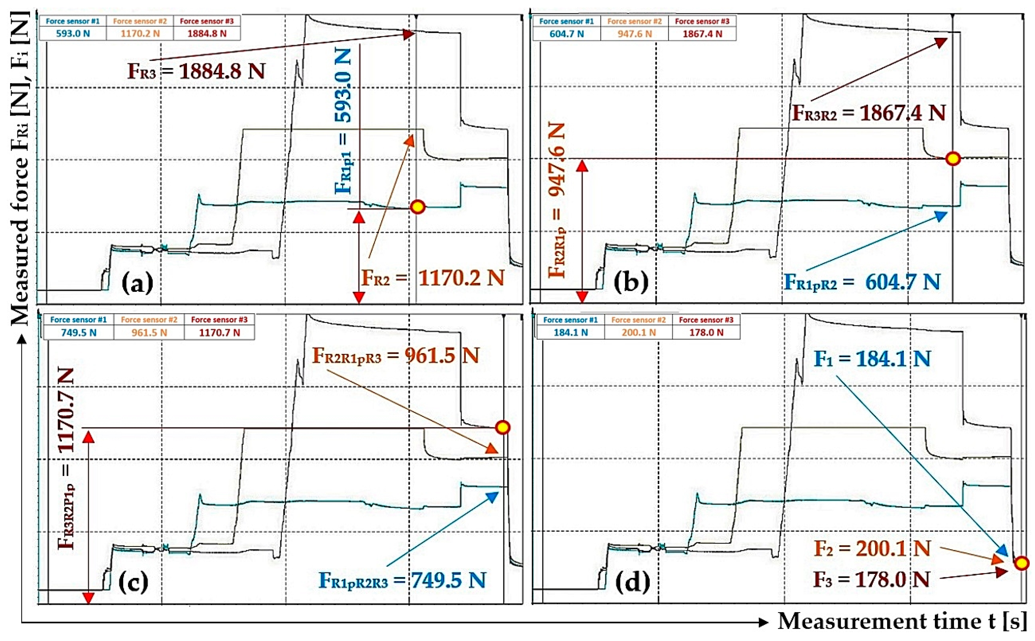
Figure 15c and Figure 16c also present the case when the hydraulic oil pressure in the spaces under the pistons of all hydraulic cylinders is the same as in the hydraulic pipeline. The highest measured value of a pulling force, see Figure 15c and Table 5, is 1170.7 N and the lowest is 749.5 N. The highest measured pulling force value is 1.56 times (56.2%) higher than the lowest measured value. The highest measured value of the pulling force, Figure 16c, is 1766.0 N and the lowest is 955.9 N; see Table 5. The highest measured value of the pulling force is 84.7% higher than the lowest measured value.
After opening valve D, which reduces the pressure of the hydraulic oil in the hydraulic pipeline and the pressure in the spaces under the pistons of the hydraulic cylinders to the value of the atmospheric pressure, the values of the pulling forces in the ropes acquire approximately the same magnitude; see Figure 15d. The highest measured value of the pulling force, Figure 15d, is 200.1 N and the lowest is 178.0 N; see Table 5. The highest measured value of the pulling force is 12.4% (1.12 times) higher than the lowest measured value. The highest measured value of the pulling force, Figure 16d, is 183.4 N and the lowest is 158.5 N; see Table 5. The highest measured value of the pulling force is 1.16 times (15.7%) higher than the lowest measured value.
According to [40], it can be stated that the efficiency of a linear hydraulic motor reaches values of 94% to 96%. The difference in the measured values of pulling forces, see Figure 12d, Figure 15c and Figure 16c, on the laboratory equipment (Figure 5), acting in individual ropes when valves A to C are open, is a consequence of the total resistance force, which can be expressed for a specific hydraulic cylinder as the sum of the frictional forces in the contact surface of the piston seal with the inner cylindrical surface of the hydraulic cylinder body and of the rod seal with the cap.
The difference between the highest and the lowest measured pulling force in the ropes, see Figure 12d, is Fdif = 1613.6 − 1137.2 = 476.4 N. This value corresponds to the hydraulic oil pressure under the hydraulic cylinder piston (cross-section Shc [m2] (2)) p = Fdif/Shc = 476.4/4.9·10−4 = 9.7·105 Pa. With the calculated mean value pr = 2.67 MPa of the actual pressures under the pistons of the hydraulic cylinders (pp1 = 3.29 MPa, pp2 = 2.39 MPa and pp3 = 2.32 MPa), the pressure p = 1 MPa becomes 37.5% of the value pr = 2.67 MPa.
The difference between the highest and lowest measured pulling force in the ropes, see Figure 15c, is Fdif = 1170.7 − 749.5 = 421.2 N. This value corresponds to the hydraulic oil pressure under the hydraulic cylinder piston p = Fdif/Shc = 421.2/4.9·10−4 = 8.6·105 Pa.
The difference between the highest and lowest measured pulling force in the ropes, see Figure 16c, is Fdif = 1766.0 − 955.9 = 810.1 N. This value corresponds to the hydraulic oil pressure under the hydraulic cylinder piston p = 1.7·106 Pa.
Figure 17b also presents the case when the hydraulic oil pressure in the spaces under the pistons of all hydraulic cylinders is the same as in the hydraulic pipeline. The highest measured value of the pulling force is 979.7 N and the lowest is 559.4 N. The highest measured value of the pulling force is 1.75 times (75.1%) higher than the lowest measured value.
The highest measured value of the pulling force, see Figure 17c, is 674.2 N and the lowest is 652.6 N. The highest measured pulling force value is 1.03 times (3.3%) higher than the lowest measured value.
The high differences in the values of pulling forces in the ropes (Figure 12d, Figure 15c, Figure 16c and Figure 17b), when valves A to C are open, are caused by resistance forces that prevent the piston rods from being pushed out of the hydraulic cylinder bodies without the action of external forces. The magnitudes of the resistance against the movement of the piston rod in the body of the hydraulic cylinder vary for hydraulic cylinders of different constructions. The amount of resistance against the movement of the piston rod depends on the type of seals used and the clearance (which ensures the tightness of the hydraulic oil pressure) between the seal and the inner cylindrical surface of the hydraulic cylinder body. The phases of experimental measurements carried out in the Laboratory of Research and Testing, Department of Machine and Industrial Design, Faculty of Mechanical Engineering, VSB-Technical University of Ostrava, when valves A to C were opened, proved that due to the resistance forces acting against the movement of piston rods in the bodies of hydraulic cylinders, the different values of pulling forces in the ropes were not equalized to the same value. This phase is represented by Area “1”; see Figure 18. Due to the fact that during the measurements of pulling forces in the ropes, the ropes were static (i.e., they were not carried away by friction in the grooves of the friction discs, as is the case with the friction drives of elevators or mining machines), no external dynamic forces act on the ropes after opening valves A to C.
When additional pulling forces were applied to the ropes (due to the lateral deflection of the ropes with the help of the hand of the operator of the laboratory equipment), see Figure 18 Area “2”, and these overcame the resistance forces in the hydraulic cylinders, the pulling forces in all ropes were equalized to the same values; see Figure 18 Area “3”.
Based on the measurements carried out, it can be stated that in order to achieve the easiest and most accurate hydraulic equalization of the pulling forces in ropes, it is particularly necessary to choose suitable hydraulic cylinders and take into account their operating parameters, which are mainly the tensile/compressive force, operating pressure and structural dimensions. The structural dimensions of the hydraulic cylinder and the hydraulic oil pressure affect the amount of the resistance force required to extend/retract the piston rod into the hydraulic cylinder body. The partial components of the total resistance force required for extending/retracting the piston rod into the body of the hydraulic cylinder are, see Figure 18, rod seal resistance, rod bearing resistance, piston seal resistance, piston bearing resistance and wiper friction resistance.
To achieve an absolutely accurate distribution of the total pulling force among the specified number of load-bearing ropes, it would be necessary for the resistance against the extending/retracting of the piston rod into the body of the hydraulic cylinder to be zero. Due to the fact that friction arises (and cannot be completely eliminated) during the movement of the piston rod in the body of the hydraulic cylinder, it is necessary to limit this friction to the smallest possible extent by using the most suitable type of hydraulic cylinder, so that it is possible to derive the values of pulling forces in partial ropes with only minor deviations.
5. Conclusions
The performed measurements made it possible to trace that there is no complete equalization of the different values of the pulling forces in all three ropes (if there are no additional pulling forces in the ropes) (Figure 12d, Figure 15c, Figure 16c and Figure 17b), and this is because of the resistance forces that act when the piston rods are pushed out of the hydraulic cylinder bodies.
In the laboratory equipment, the ropes are static, i.e., they are not in motion as in real mining equipment/elevators, where the traction/load-bearing ropes are carried by the grooves of the friction discs due to friction. As a result of the generated dynamic pulling forces that act in the longitudinal axes of the traction/load-bearing ropes during their movement at lifting speed, and when they pass through the friction discs, these pulling forces in the ropes are transferred to the piston rods of the hydraulic cylinders and reduce or completely eliminate (if they are greater than the resistance against the extension of the piston rod) the magnitude of the frictional force when the piston rod is extended from the hydraulic cylinder body. The absence of dynamic pulling forces in the ropes of the laboratory equipment was replaced by additional pulling forces created by the operator of the laboratory equipment, thus achieving an exact equalization of the pulling forces in all three ropes (Figure 17c and Figure 18).
Several principles are currently known in the consumer market allowing for the subtraction of the acting tensile force in the ropes and eventually offsetting the different tensile force values in the individual ropes.
Well known is the principle of a rope sensor, e.g., [41], measuring the tensile force in the rope using the principle of the bending deformation of the beam loaded with a single force.
A certain limitation in the use of the method for determining the tensile force in the carrier rope with a rope sensor can also be seen in the necessity to have this device mechanically attached on the ropes during the offset of the tensile forces. In a phase of operation, when new ropes are being installed in the elevator system and it is necessary to move the cage within the elevator shaft in order to offset tensile forces in the individual ropes, there is a risk of the collision of the sensors attached to the ropes with the friction disc or other elements in the elevator shaft.
Another significant limitation presents the possibility of damaging the power cables to the tensometric sensors of the rope sensors, when there is a two-way movement of the elevator cage. When the cage is moving within the elevator shaft, then the carrier ropes and thus also the rope sensors, which are mechanically attached to the cross-sections of the ropes, are in motion as well.
The actual value of the tensile force acting on the rope axis is not directly measured by the rope sensor; it is determined proportionally from the normal force exerted, i.e., the force perpendicular to the rope axis. This normal force is a resultant of the components of the acting tensile forces in inclined sections of the measured rope and acts on the central contact member of the rope sensor. The actual value of the tensile force in the rope must therefore be determined by the comparative method. The accuracy of determining the actual tensile force in the rope is affected by the reshaping (deformation) of the rope sensor body and depends on the angle of inclination of the rope section and the distance of the gripping points of all contact points.
From the experimental measurements carried out (presented in Section 3 Results), it follows that by using the pressure of the hydraulic oil in the hydraulic circuit, which connects the spaces below or above the pistons of single-acting or double-acting hydraulic cylinders, it is very easy to achieve the same magnitudes of pulling forces in the ropes.
In this article, double-acting hydraulic cylinders are used to carry out experiments with the spaces above the pistons interconnected by a hydraulic pipe with only hydrostatic pressure. If single-acting hydraulic cylinders were used, then the experimental measurements carried out on the laboratory equipment would show absolutely identical results, provided that the hydraulic oil pressure supplied to the space above the hydraulic cylinder pistons would be half the magnitude of the pressure delivered to the space above the hydraulic cylinder pistons. The internal cross-section of the hydraulic cylinder (space above the piston) is larger; see Sc [m2] and Shc [m2] (2). The magnitude of the pulling force in the rope FRc = FR·k1 [N] (3), where k1 = Sc/Shc.
One unique contribution of this article—and a new finding—is the set of tables listing the values of the measured pulling forces in ropes when the spaces under the pistons of the hydraulic cylinders were connected to each other. The new findings can be observed in the attached graphs of the measured pulling forces in the ropes in the individual phases of the experiments, which made it possible to specify all the conditions in order to be able to declare that the initially different magnitudes of the pulling forces in the ropes become the same if the hydraulic device specified in this article is used.
Author Contributions
Conceptualization, L.H. and J.F.; methodology, L.H.; software, L.H.; validation, J.F. and Š.P.; formal analysis, L.H.; investigation, L.H.; resources, L.H.; data curation, J.F.; writing—original draft preparation, L.H.; writing—review and editing, L.H.; visualization, L.H. and J.F.; supervision, J.F.; project administration, L.H.; funding acquisition, L.H. All authors have read and agreed to the published version of the manuscript.
Funding
This research was funded by “Research and innovation of modern processes and technologies in industrial practice”, grant number SP2024/001 and MŠMT ČR (Ministry of education youth and sports).
Institutional Review Board Statement
Not applicable.
Informed Consent Statement
Not applicable.
Data Availability Statement
Conflicts of Interest
The authors declare no conflicts of interest. The funders had no role in the design of the study; in the collection, analyses, or interpretation of data; in the writing of the manuscript; or in the decision to publish the results.
References
- DIN EN 81-20; Safety Rules for the Construction and Installation of Lifts—Lifts for the Transport of Persons and Goods—Part 20: Passenger and Goods Passenger Lifts (In Czech: Bezpečnostní Předpisy pro Konstrukci a Montáž Výtahů—Výtahy pro Dopravu Osob a Nákladů—Část 20: Výtahy pro Dopravu Osob a Osob a Nákladů). European Standard: Brussels, Belgium, 2020. Available online: https://www.technickenormy.cz/din-en-81-20-safety-rules-for-the-construction-and-installation-of-lifts-lifts-for-the-transport-of-persons-and-goods-part-20-passenger-and-goods-passenger-lifts-7/ (accessed on 1 June 2020).
- EN 12385-5:2002; Steel Wire Ropes—Safety—Part 5: Stranded Ropes for Lifts (In Czech: Ocelová Drátěná Lana—Bezpečnost—Část 5: Pramenná Lana pro Výtahy). European Standard: Brussels, Belgium, 2021. Available online: https://www.technickenormy.cz/csn-en-12385-5-ocelova-dratena-lana-bezpecnost-cast-5-pramenna-lana-pro-vytahy-3/ (accessed on 1 November 2021).
- Směrnice Evropského Parlamentu a Rady 2000/9/ES. Available online: https://eur-lex.europa.eu/legal-content/CS/TXT/PDF/?uri=CELEX:32000L0009 (accessed on 20 March 2020).
- Zákon č. 22/1997 Sb.: Zákon o Technických Požadavcích na Výrobky a o Změně a Doplnění Některých Zákonů. Available online: https://www.zakonyprolidi.cz/cs/1997-22 (accessed on 27 February 1997).
- Nařízení vlády č. 122/2016 Sb.: Nařízení Vlády o Posuzování Shody Výtahů a Jejich Bezpečnostních Komponent. Available online: https://www.zakonyprolidi.cz/cs/2016-122 (accessed on 18 April 2016).
- Toralkar, S. Traction in Elevators; Elevator World India: Bangalore, India, 2009; pp. 84–88. [Google Scholar]
- Yuda, S.M.; Pane, M.; Elyes, F. Design of Top Traction Elevator in Building 6 Floor. VANOS J. Mech. Eng. Educ. 2021, 6, 107–115. [Google Scholar] [CrossRef]
- Soyaslan, M.; Avsar, Y.; Fenercioglu, A.; Sarihan, F. Design and production of belt drive elevator traction machine: Modelling of double side belt system. Politek. Derg. 2023, 1. [Google Scholar] [CrossRef]
- Annett, F.A. Elevators: Electric and Electrohydraulic Elevators, Escalators, Moving Sidewalks and Ramps. 1960. Available online: https://cir.nii.ac.jp/crid/1130282270583238784 (accessed on 15 May 2022).
- Wrap Traction Overhead Type Elevator. Available online: https://crownelevators.in/images/ropes/elevator-cable-setups.png (accessed on 3 June 2023).
- Hrabovsky, L.; Maslaric, M. Device designed for detection and setting the required tensile force in ropes. Adv. Sci. Technol. Res. J. 2018, 12, 200–206. [Google Scholar] [CrossRef] [PubMed]
- Hrabovsky, L.; Michalik, P. A tension equalizer in lift carrying ropes. Adv. Sci. Technol. Res. J. 2017, 11, 326–332. [Google Scholar] [CrossRef] [PubMed]
- Mingxiang, H.; Dequan, C.; Lizhi, P.; Longbin, Z.; Bo, T. Design of Monitoring Sensors for Rope Force in Assembling Tower with Inside Suspension Pole. In Proceedings of the 2021 International Conference on Advanced Electrical Equipment and Reliable Operation (AEERO), Beijing, China, 15–17 October 2021; pp. 1–6. [Google Scholar]
- Barnes, M.; Rhiner, M. Constructional Stretch and Hoist-Rope Tension. Available online: https://elevatorbooks.com/wp-content/uploads/2019/02/EW0712.pdf (accessed on 20 March 2024).
- Kim, D.B.; Kim, G.S. A Study on the Development of an Elevator Rope Tension Automatic Equalizer. J. Korean Soc. Manuf. Process Eng. 2020, 19, 60–66. [Google Scholar] [CrossRef]
- Cvik, K.; Golasowski, J.; Hinner, V. Experience with operation of multi-rope hoisting equipment without any device for automatic equalization of tension in hoisting ropes. Uhli (Czechoslovakia) 1989, 37, 374–377. [Google Scholar]
- Zhang, X.; Jin, H. Design of strain tension sensor of steel wire rope used in the coal mine. In Proceedings of the Seventh International Symposium on Precision Mechanical Measurements, Xiamen, China, 29–31 January 2016. [Google Scholar]
- Liu, P.; Zhang, X.; Huang, Y.K.; Rong, J.X. The analysis of wire rope tension sensor elastic body based on solidworks. Adv. Mater. Res. 2012, 591–593, 1603–1606. [Google Scholar] [CrossRef]
- Singh, M.K.; Mahto, A.; Thakur, R.N.; Sinha, A. Failure analysis of wire rope used for hoisting in mining: A case study. J. Fail. Anal. Prev. 2007, 7, 87–91. [Google Scholar] [CrossRef]
- Jin, H.W.; Zhang, X. Design of dynamic tension detection system of multi-hoisting wire rope. Appl. Mech. Mater. 2012, 201, 565–568. [Google Scholar] [CrossRef]
- Lei, G.; Xu, G.; Zhang, X.; Zhang, Y.; Song, Z.; Xu, W. Study on dynamic monitoring of wire rope tension based on the particle damping sensor. Sensors 2019, 19, 388. [Google Scholar] [CrossRef] [PubMed]
- Hrabovsky, L. Tension force equalizer in a rope system using a proximity sensor. Zesz. Nauk. Transp./Politech. Śląska 2021, 110, 35–44. [Google Scholar] [CrossRef]
- Yao, M.; Jin, Y.; Zhao, M.; Xu, S. Research and Application of Heavy-Equipment Parachute Rope Tension Sensor. J. Sens. 2018, 7631727. [Google Scholar] [CrossRef]
- Zhao, M.; Tian, X.H.; Zhang, R.Y.; Wu, L.L. A wireless passive tension sensor. In Proceedings of the 16th International Conference on Mechatronics-Mechatronika, Brno, Czech Republic, 3–5 December 2014; pp. 473–476. [Google Scholar]
- Xu, G.; Da, J.; Zhang, X.; Han, M.; Xia, T. A novel tension monitoring device of multi-rope friction hoister by using acoustic filtering sensor. J. Vibroeng. 2016, 18, 5537–5552. [Google Scholar] [CrossRef]
- Hrabovsky, L.; Borovsky, D. Laboratory device for checking the functionality of the elevator rope sensors. Manag. Syst. Prod. Eng. 2021, 29, 59–64. [Google Scholar] [CrossRef]
- Lei, G.; Xu, G.; Zhang, X.; Tian, B. Study on dynamic characteristics and compensation of wire rope tension based on oil pressure sensor. Adv. Mech. Eng. 2019, 11, 1687814019836024. [Google Scholar] [CrossRef]
- Mitsantisuk, C.; Ohishi, K.; Katsura, S. Control of interaction force of twin direct-drive motor system using variable wire rope tension with multisensor integration. IEEE Trans. Ind. Electron. 2012, 59, 498–510. [Google Scholar] [CrossRef]
- Daifuku, S.; Li, B.; Yamaguchi, Y.; Nagatoshi, M.; Imado, K. Development of tension meter for wire rope and lashing belt. J. Mech. Syst. Transp. Logist. 2013, 6, 65–72. [Google Scholar] [CrossRef]
- Frydrysek, K.; Michenkova, S.; Pleva, L.; Koutecky, J.; Fries, J.; Peterek, D.K.; Pokorny, J. Mechanics of screw joints solved as beams placed in a tangential elastic foundation. Appl. Sci. 2021, 11, 5616. [Google Scholar] [CrossRef]
- Liu, S.; Zeng, X.; Ni, M.; Liu, Z.; Mo, L. Tension measurement for wire ropes based on magneto-elastic effect. In Proceedings of the 2018 Prognostics and System Health Management Conference (PHM-Chongqing), Chongqing, China, 26–28 October 2018; pp. 50–56. [Google Scholar]
- Konstantinov, M.Y.; Kiseleva, M.V.; Novikov, A.F. Equalizing forces in ropes of a multi-rope hoisting system. Ugol’Ukr (Ukrainian SSR) 1981, 5, 32–33. [Google Scholar]
- Ruční Olejová Pumpa Jednočinná s Nádrží 3L. Available online: https://www.kardanka.cz/rucni-olej-pumpa-jednocinna-s-nadrzi-3l-23987 (accessed on 20 January 2023).
- Standardní Dvoučinný Hydraulický válec 32/20/50. Available online: https://www.kardanka.cz/standardni-dvoucinny-hydraulicky-valec-32/20/50-205-mm-35722 (accessed on 11 August 2023).
- Šestipramenné lano 6x19M-WSC. Available online: https://www.lana-retezy.cz/sestipramenna-lana/sestipramenne-lano-6x19m-wsc/ (accessed on 26 December 2022).
- ČSN EN 12385-4; Steel Wire Ropes—Safety—Part 4: Stranded Ropes for General Lifting Applications (In Czech: Ocelová Drátěná Lana—Bezpečnost—Část 4: Pramenná Lana pro Všeobecné Zdvíhací Účely). TECHNOR print, s.r.o.: Hradec Kralove, Czech Republic, 2004. Available online: https://www.technicke-normy-csn.cz/csn-en-12385-4-024302-162155.html (accessed on 20 May 2004).
- AST—Snímač Typu “S”. Available online: https://www.format1.cz/files/products_files/a/AST.pdf (accessed on 13 January 2023).
- Technical Reference Manual DEWESoft DS-NET V20-1. Available online: https://d36j349d8rqm96.cloudfront.net/3/6/Dewesoft-DS-NET-Manual-EN.pdf (accessed on 26 April 2012).
- DEWESoft Previous Releases. DEWESoft® X2 SP5. Available online: https://dewesoft.com/download/dewesoftx-previous-releases (accessed on 11 July 2002).
- DIN ISO 6022:2008-06; Hydraulic Fluid Power—Mounting Dimensions for Single Rod Cylinders, 25 MPa (250 bar) Series. NORMSERVIS: Hamry nad Sázavou, Czech Republic, 2008. Available online: https://eshop.normservis.cz/norma/diniso-6022-1.6.2008.html (accessed on 1 July 2008).
- Hrabovsky, L. Apparatus producing an even distribution of strain into carriers. IOP Conf. Ser. Mater. Sci. Eng. 2017, 245, 022097. [Google Scholar] [CrossRef]
Figure 1.
Load-bearing ropes of traction elevators guided by the grooves of the friction disc.

Figure 2.
Structural design of laboratory equipment created in SolidWorks® Premium SP 5.0.

Figure 3.
Laboratory equipment (a) basic dimensions and components and (b) hydraulic circuit. 1—steel structure; 2—steel rope; 3—hydraulic cylinder; 4—tensometric force sensor; 5—manual hydraulic pump; 6—hydraulic circuit.
Figure 3.
Laboratory equipment (a) basic dimensions and components and (b) hydraulic circuit. 1—steel structure; 2—steel rope; 3—hydraulic cylinder; 4—tensometric force sensor; 5—manual hydraulic pump; 6—hydraulic circuit.

Figure 4.
Hydraulic oil pressure in the spaces under the hydraulic cylinder pistons (a) of different magnitudes pp1 ≠ pp2 ≠ pp3 [Pa] and (b) of the same magnitude pp1 = pp2 = pp3 = ppr [Pa].
Figure 4.
Hydraulic oil pressure in the spaces under the hydraulic cylinder pistons (a) of different magnitudes pp1 ≠ pp2 ≠ pp3 [Pa] and (b) of the same magnitude pp1 = pp2 = pp3 = ppr [Pa].

Figure 5.
Laboratory equipment simulating method of hydraulic equalization of pulling force values in ropes.
Figure 5.
Laboratory equipment simulating method of hydraulic equalization of pulling force values in ropes.

Figure 6.
Measuring chain—a sequence of connected instruments and devices enabling the detection and processing of measured signals. 1—tensometric force sensor; 2—D-sub DE-9 connector; 3—DS NET BR4 module; 4—DS GATE module; 5—Ethernet cable; 6—ASUS K72JR-TY131; 7—DEWESoft® X2 SP5.
Figure 6.
Measuring chain—a sequence of connected instruments and devices enabling the detection and processing of measured signals. 1—tensometric force sensor; 2—D-sub DE-9 connector; 3—DS NET BR4 module; 4—DS GATE module; 5—Ethernet cable; 6—ASUS K72JR-TY131; 7—DEWESoft® X2 SP5.

Figure 7.
Steel ropes (a) attached to the upper part, (b) guided by the grooves of the pulleys of the laboratory equipment.
Figure 7.
Steel ropes (a) attached to the upper part, (b) guided by the grooves of the pulleys of the laboratory equipment.

Figure 8.
Ends of the steel ropes attached (a) to the upper part and (b) to the lower part of the laboratory equipment.
Figure 8.
Ends of the steel ropes attached (a) to the upper part and (b) to the lower part of the laboratory equipment.

Figure 9.
Time recording of measured pulling forces in ropes by tensometric force sensors on laboratory equipment.
Figure 9.
Time recording of measured pulling forces in ropes by tensometric force sensors on laboratory equipment.

Figure 10.
Supply pipe pressure pp = pp3 [N] (a) greater than pressure pp1 [N] and (b) less than pressure pp1 [N].
Figure 10.
Supply pipe pressure pp = pp3 [N] (a) greater than pressure pp1 [N] and (b) less than pressure pp1 [N].

Figure 12.
Measured pulling forces in ropes with (a) valves A to D closed, (b) valve A open and valves B to D closed, (c) valves A and B closed and valves C and D closed and (d) valves A to C open and valve D closed.
Figure 12.
Measured pulling forces in ropes with (a) valves A to D closed, (b) valve A open and valves B to D closed, (c) valves A and B closed and valves C and D closed and (d) valves A to C open and valve D closed.

Figure 13.
The pulling force in the rope, with valves B and C of the hydraulic circuit closed, when (a) pumping oil under the piston of the hydraulic cylinder with valve A open, (b) applying the pulling force in the rope with valve A closed and (c) opening valve A.
Figure 13.
The pulling force in the rope, with valves B and C of the hydraulic circuit closed, when (a) pumping oil under the piston of the hydraulic cylinder with valve A open, (b) applying the pulling force in the rope with valve A closed and (c) opening valve A.

Figure 15.
The detected pulling forces in the ropes, generated by applying hydraulic oil pressure under the hydraulic cylinder pistons: (a) valve A open, valves B to D closed; (b) valve B open, valves C and D closed; (c) valve C open, valve D closed and (d) valve D open.
Figure 15.
The detected pulling forces in the ropes, generated by applying hydraulic oil pressure under the hydraulic cylinder pistons: (a) valve A open, valves B to D closed; (b) valve B open, valves C and D closed; (c) valve C open, valve D closed and (d) valve D open.

Figure 16.
The detected pulling forces in the ropes, generated by applying hydraulic oil pressure under the hydraulic cylinder pistons: (a) valve A open, valves B to D closed; (b) valve B open, valves C and D closed; (c) valve C open, valve D closed and (d) valve D open.
Figure 16.
The detected pulling forces in the ropes, generated by applying hydraulic oil pressure under the hydraulic cylinder pistons: (a) valve A open, valves B to D closed; (b) valve B open, valves C and D closed; (c) valve C open, valve D closed and (d) valve D open.

Figure 17.
The detected pulling forces in the ropes, generated by applying hydraulic oil pressure under the hydraulic cylinder pistons. (a) Valve A to D closed. Opened valves (b), (c) A to C, valve D closed, and (d) A to D.
Figure 17.
The detected pulling forces in the ropes, generated by applying hydraulic oil pressure under the hydraulic cylinder pistons. (a) Valve A to D closed. Opened valves (b), (c) A to C, valve D closed, and (d) A to D.

Figure 18.
Phases to achieve the same magnitudes of pulling forces in the load-bearing ropes of the laboratory equipment.
Figure 18.
Phases to achieve the same magnitudes of pulling forces in the load-bearing ropes of the laboratory equipment.

Table 3.
The pulling force in the rope and the pressure of the hydraulic oil in the space under the hydraulic cylinder piston and in the supply pipe.
Table 3.
The pulling force in the rope and the pressure of the hydraulic oil in the space under the hydraulic cylinder piston and in the supply pipe.
| n | Fp | FR1 | pp | pp1 | FR1p | pp1p |
|---|---|---|---|---|---|---|
| [N] | [MPa] | [N] | [MPa] | |||
| 1 | 653.0 1 | 1158.7 2 | 1.33 | 2.36 | 1036.0 3 | 2.11 |
| 2 | 285.9 | 618.5 | 0.58 | 1.26 | 593.7 | 1.21 |
| 3 | 406.5 | 938.2 | 0.83 | 1.91 | 912.4 | 1.86 |
Table 5.
The pulling force in the rope and the pressure of the hydraulic oil in the space under the hydraulic cylinder piston and in the supply pipe.
Table 5.
The pulling force in the rope and the pressure of the hydraulic oil in the space under the hydraulic cylinder piston and in the supply pipe.
| n | FR1p1 | FR2R1p1 | FR1p1R2 | FR3R2 | FR3R2R1p | FR1pR2R3 | FR2R1pR3 | F1 | F2 | F3 |
|---|---|---|---|---|---|---|---|---|---|---|
| [N] | ||||||||||
| 1 | 593.0 1 | 947.6 2 | 604.7 2 | 1867.4 2 | 1170.7 3 | 749.5 3 | 961.5 3 | 184.1 4 | 200.1 4 | 178.0 4 |
| 2 | 1034.5 | 955.6 | 1170.2 | 1656.7 | 1005.4 | 1170.2 | 1358.9 | 534.5 | 556.5 | 503.4 |
| 3 | 1104.0 5 | 1170.2 6 | 940.2 6 | 1766.0 6 | 1766.0 7 | 955.9 7 | 1170.2 7 | 169.3 8 | 183.4 8 | 158.5 8 |
Disclaimer/Publisher’s Note: The statements, opinions and data contained in all publications are solely those of the individual author(s) and contributor(s) and not of MDPI and/or the editor(s). MDPI and/or the editor(s) disclaim responsibility for any injury to people or property resulting from any ideas, methods, instructions or products referred to in the content. |
© 2024 by the authors. Licensee MDPI, Basel, Switzerland. This article is an open access article distributed under the terms and conditions of the Creative Commons Attribution (CC BY) license (https://creativecommons.org/licenses/by/4.0/).
Share and Cite
MDPI and ACS Style
Hrabovský, L.; Fries, J.; Pravda, Š. A Laboratory Machine Verifying the Operation of a Hydraulic Rope Equalizer with Tensometric Sensors. Sensors 2024, 24, 2588. https://doi.org/10.3390/s24082588
AMA Style
Hrabovský L, Fries J, Pravda Š. A Laboratory Machine Verifying the Operation of a Hydraulic Rope Equalizer with Tensometric Sensors. Sensors. 2024; 24(8):2588. https://doi.org/10.3390/s24082588
Chicago/Turabian StyleHrabovský, Leopold, Jiří Fries, and Štěpán Pravda. 2024. "A Laboratory Machine Verifying the Operation of a Hydraulic Rope Equalizer with Tensometric Sensors" Sensors 24, no. 8: 2588. https://doi.org/10.3390/s24082588
Note that from the first issue of 2016, this journal uses article numbers instead of page numbers. See further details here.