An Integrated MEMS Gyroscope Array with Higher Accuracy Output

Micro and Nano Electro Mechanical System Laboratory, Northwestern Polytechnical University, Xi’an City, Shaanxi Province, P. R. China, 710072
*
Author to whom correspondence should be addressed.
Sensors 2008, 8(4), 2886-2899; https://doi.org/10.3390/s8042886
Submission received: 29 October 2007
/
Accepted: 21 April 2008
/
Published: 28 April 2008
(This article belongs to the Special Issue Intelligent Sensors)
Abstract
:In this paper, an integrated MEMS gyroscope array method composed of two levels of optimal filtering was designed to improve the accuracy of gyroscopes. In the first-level filtering, several identical gyroscopes were combined through Kalman filtering into a single effective device, whose performance could surpass that of any individual sensor. The key of the performance improving lies in the optimal estimation of the random noise sources such as rate random walk and angular random walk for compensating the measurement values. Especially, the cross correlation between the noises from different gyroscopes of the same type was used to establish the system noise covariance matrix and the measurement noise covariance matrix for Kalman filtering to improve the performance further. Secondly, an integrated Kalman filter with six states was designed to further improve the accuracy with the aid of external sensors such as magnetometers and accelerometers in attitude determination. Experiments showed that three gyroscopes with a bias drift of 35 degree per hour could be combined into a virtual gyroscope with a drift of 1.07 degree per hour through the first-level filter, and the bias drift was reduced to 0.53 degree per hour after the second-level filtering. It proved that the proposed integrated MEMS gyroscope array is capable of improving the accuracy of the MEMS gyroscopes, which provides the possibility of using these low cost MEMS sensors in high-accuracy application areas.
1. Introduction
Angular rate sensors have wide applications in the automotive, aerospace and consumer electronics sectors. Gyroscopes fabricated by microelectromechanical system (MEMS) technology offer revolutionary improvements in cost, size, and ruggedness relative to fiber-optic and spinning mass technologies. At least twenty angular rate sensors of this kind with different structures and principles have been presented by various groups in the past twenty years. However, the current state-of-the-art MEMS gyroscopes have low-grade performance and can not compete with the established sensors in high-accuracy application areas such as guidance and navigation, where the bias drift of the gyroscope is the most popular term used to define performance. At the end of 2007 the best published accuracy for a MEMS gyroscope was about one degree drift per hour [1], which was demonstrated with temperature control by the Draper laboratory before 1998 [2]. Up to 2007, no MEMS gyroscope with an accuracy higher than one degree drift per hour had been reported, which means that to improve the MEMS gyroscope accuracy in traditional ways of designing good mechanical sensing scheme or signal conditioning circuitry is not an efficient approach and new methods should be proposed to improve the accuracy of these devices.
The advantages of using multiple sensors over a single sensor to improve the accuracy of acquired information about an object have been recognized and employed by many engineering disciplines ranging from applications such as a medical decision-making aid system to a combined navigation system [3]. Weis and Allan presented a high-accuracy clock with a month error of one second through combining three inexpensive wrist watches with month errors of 40 seconds in 1992 [4]. This new time technology was named 'smart clock'. The smart clock enhances the accuracy or stability of a clock or by characterizing it against an external standard such as U.S. time standard at NIST. Actually this technology used heterogeneous sensor data fusion to improve the accuracy. Recently, some researchers have begun to take the similar idea to improve the accuracy of MEMS gyroscope. Bayard combined four inexpensive MEMS gyroscopes to form a virtual sensor with higher accuracy output, and called this technology ‘virtual gyroscope’ [5]. In the virtual gyroscope the random noise of the gyroscope was estimated by using the Kalman filtering for the further compensation, thus its accuracy was improved. The correlation between the gyroscopes was used to establish the covariance matrix of the system random noise for filtering computation and better accuracy improvements. In contrast with the smart clock, the virtual gyroscope used homogeneous sensor data fusion instead of the heterogeneous one to improve the sensor accuracy. Lam proposed a very interesting concept to enhance the accuracy of MEMS sensors via dynamic random noise characterization and calibration [3, 6, 7]. The compensation offers both filtering and cancellation capability to effectively null out the MEMS sensors noise sources. The method used both the heterogeneous sensor data fusion and homogeneous sensor data fusion to improve the sensor accuracy. The first compensation uses external aiding sensors data such as GPS sensors, thus the high noise drift errors such as bias, scale factor, and misalignment errors inherently existing in MEMS sensors will be eliminated. The second compensation uses signal isolation and stochastic model propagation to dynamically monitor changes and identify random noise parameters of MEMS inertial sensors such as angular random walk, angular white noise and rate random walk, etc. for internal self-calibration. From these examples we could conclude that these multi sensor data fusion technologies will be very suitable for MEMS sensors to improve the accuracy due to the fact that forming multiple sensor arrays in a single silicon chip is one of the biggest advantages of the MEMS technology.
Through analyzing the current various multi-sensor fusion methods, we find that these approaches could be improved further in several ways for better accuracy improvements. In the virtual gyroscope, Bayard established the covariance matrices of process noises and measurement noises separately for the Kalman filtering. The parameters of the noise covariance matrices were stationary. However, the work conditions of the sensor especially the gyroscope are subject to changes due to many other factors such as in the case of high maneuverability. In such case, adopting the values of stationary noise sources could result in large estimation errors and low filtering performance. In order to well satisfy the requirement of high rate maneuvering operating conditions, Lam proposed a high order gyroscope model which contained scale factor and misalignment errors in addition to the usual noises such as angular random walk (ARW) and rate random walk (RRW). And a fifteen-state Kalman calibration filter was designed to enhance the performance of estimation [7]. Furthermore, a method to monitor changes real-time and dynamically identify sensors' random noise parameters such as angular random walk and rate random walk was presented. Thus the calibration filter process noise can be updated dynamically to provide accurate calibration. However, the correlation between the homogenous sensors was not employed to establish the covariance matrices of process noises and measurement noises, which is very important to improve the sensor accuracy.
Therefore, in this paper we will combine both homogeneous and heterogeneous sensor data fusion to improve the MEMS gyroscope accuracy. The proposed method consists of two levels of robust and optimal estimators. In the first level, several gyroscopes will be combined into a single effective device through minimum variance estimation approach. In the second level, the output of first level will be integrated with external aiding sensors such as magnetometers and accelerometers to improve the gyroscope accuracy to a better degree.
2. Working principle of the integrated gyroscope array
2.1 Correlations between the MEMS gyroscopes in the sensor array
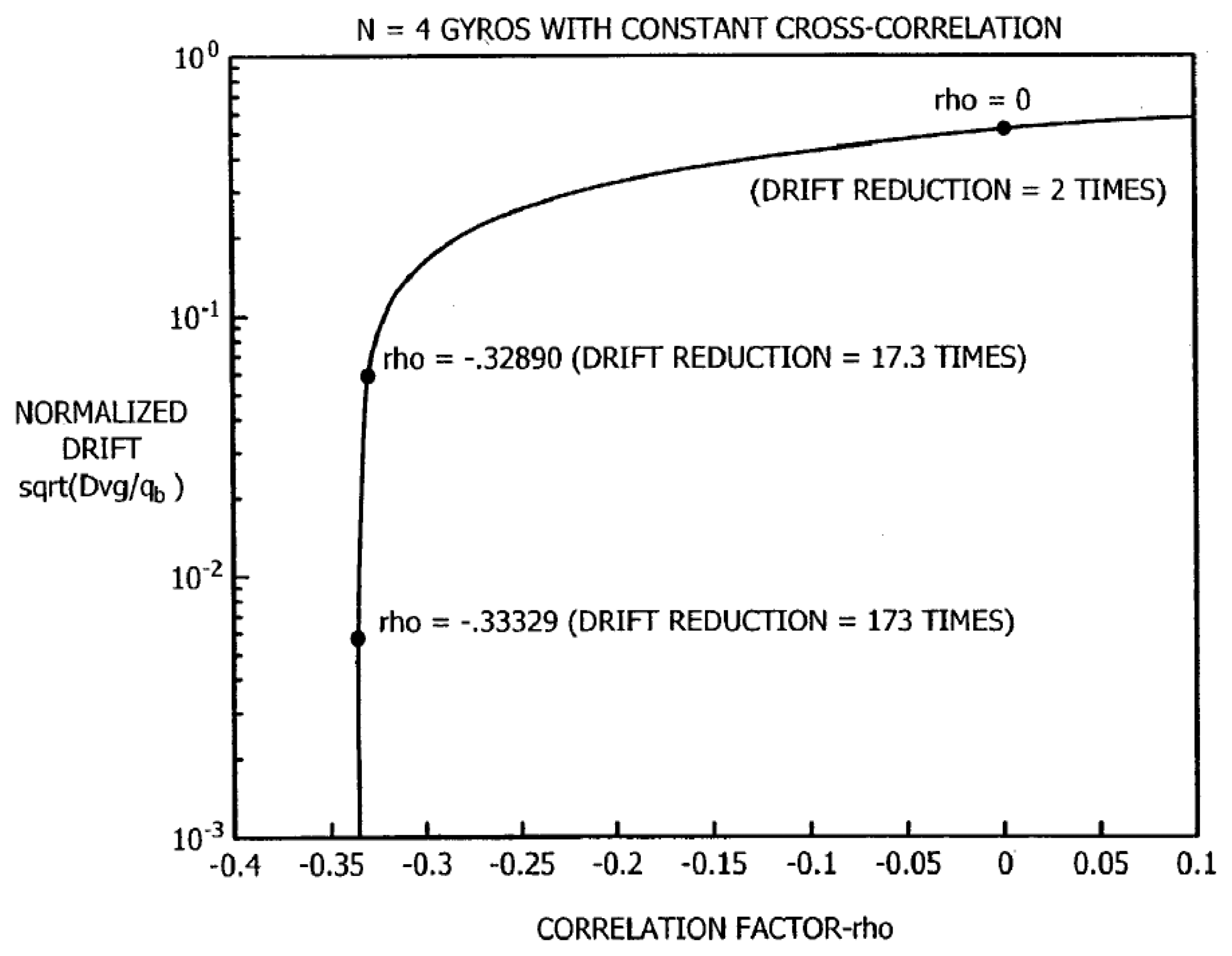
In the proposed integrated MEMS gyroscope array method, the correlation between the elements in the array is the theoretical basis of improving the accuracy. Bayard had given the accuracy improvement relationship with the correlation factor between the sensors as shown in Figure 1 [5]. According to the result [5], if the correlation does not exist the drift of a virtual gyroscope composed of N independent and identical devices will be
of the individual device. But if the sensors are correlated the potential improvement in drift is far beyond the
factor attainable using uncorrelated devices.
However, the separate MEMS gyroscopes are independent of each other. Therefore there should be no correlation between the separate sensors. But if we could fabricate these MEMS gyroscopes simultaneously on a single silicon chip within a very narrow area of about several square millimeters through various micromachining process as shown in Figure 2 [8, 9,10], and the same read-out and controlling interface circuits are supplied with these mechanical sensing elements, then we could make assumption that there is correlation between these sensors because the sensors are totally the same in the view of design and the working conditions are very similar although we do not know the exact value of the correlation yet. Currently the value is mainly determined empirically [5].
2.2 Structure of integrated MEMS gyroscope array
The proposed MEMS integrated gyroscope array method was composed of two levels, as shown in Figure 3. The first level is the gyroscope self compensation within the array, the principle of accuracy improving is similar to the virtual gyroscope except the design of filter. In this level several gyroscopes of the same kind with same specifications are formed into a gyroscope array. Each element in the sensor array works independently to measure the input angular rate. The measurement values were used to extract the random error terms through some random noise modeling method such as power spectral distribution (PSD) and Allan variance. Then the error terms are combined with the measurement values to estimate the true rate through the minimum variance estimation method. So the output angular rate via the redundant measurement and optimal estimation could surpass the performance of any element in the array.
In most applications, the gyroscopes will not be used alone but combined with other sensors such as accelerometers or magnetometers in an attitude determination system. Therefore in the integrated gyroscope array, the output of first level was undertaken by the second level filtering with aiding of the external sensors. With the external signals, the random errors of MEMS gyroscope are set as the state vectors of integrated filter. Then the output of the first-level Kalman filter could be compensated by the optimal estimation of random errors through the integrated filter, therefore the accuracy will be improved to a larger degree.
The Kalman filtering approach has the advantage of being a systematic method to ensure minimum variance rate estimation. Furthermore, it is suitable for dealing with dynamic data and has high realtime performance in comparison with other minimum variance estimation approach. So the Kalman filtering was used here to implement the integrated gyroscope array technology.
3. Design of integrated MEMS gyroscope array
3.1 Random noise modeling for MEMS gyroscope
The systematic errors of gyroscope due to biases, scale factors and misalignments could be compensated for via an on-board Kalman filtering approach [6]. While the random noise sources such as angular white noise (AWN), angular random walk (ARW) and rate random walk (RRW) are not easily estimated by the same way due to their random characteristics. Therefore in the paper the error terms for gyroscope only include the main random errors without those systematic errors. A lot of experiments have shown that the dominant random errors for the MEMS gyroscopes are ARW and RRW [6, 7], so the gyroscope in this paper is modeled as shown in Equation (1).
Where ωg is output rate, ω is the true rate, b is the gyroscope drift rate bias (rad/sec) driven by the RRW process nb, and na is the white noise corrupting the gyroscope rate measurement but becoming the angular random walk at the gyroscope angle level.
Using the above gyroscope model the units for each term were unified through the scaling as shown in Fig. 4, where the Ts was the sampling period.
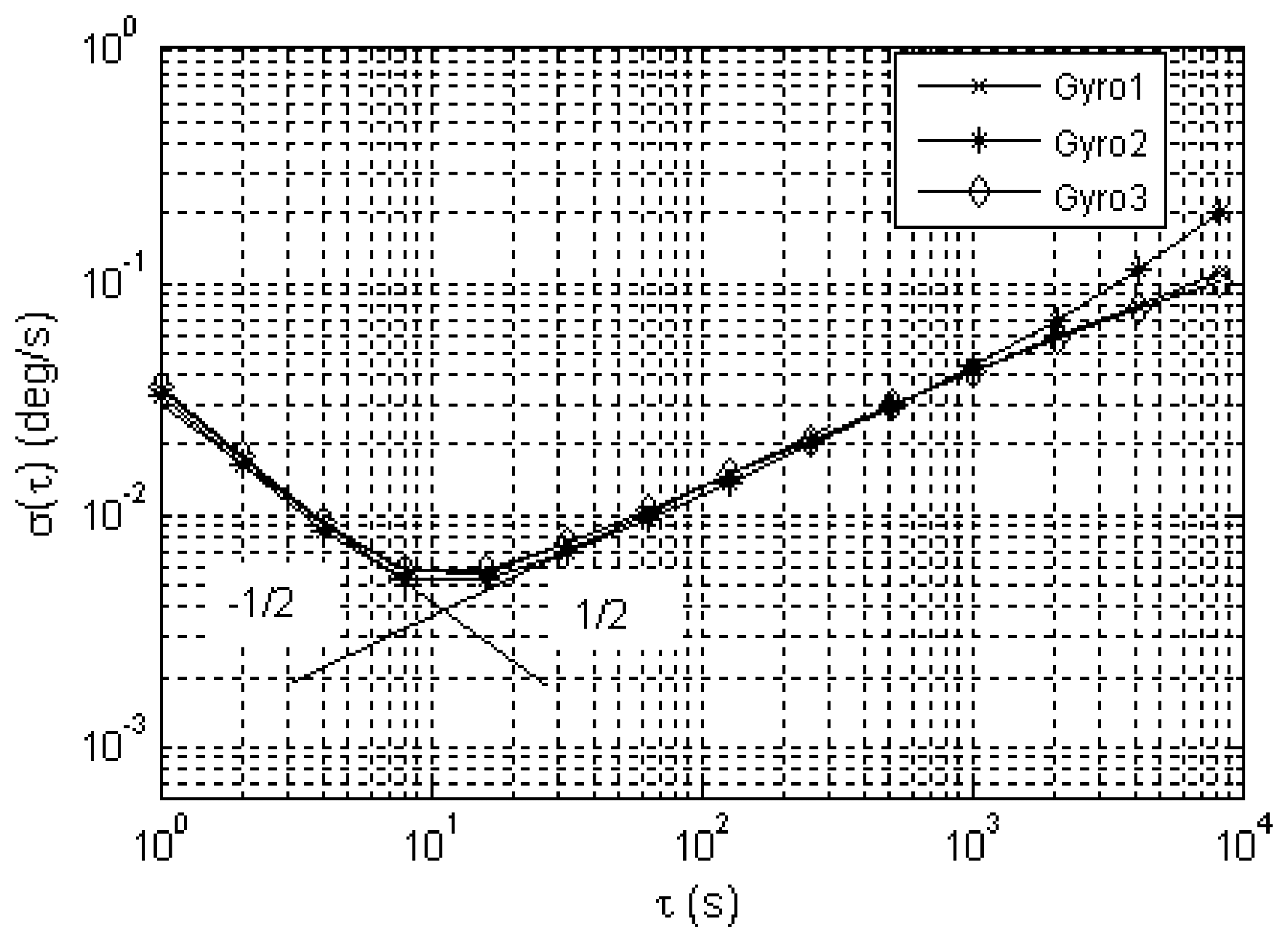
Computation of the Allan variance is a powerful method for estimating the gyroscope random noise sources [6, 7, 10, 11]. If the Allan variance is defined as
, then the random error terms such as ARW, bias drift and RRW could be obtained from the log-log plot of σ (τ) versus τ (Fig. 5). The specific values were shown in Table 1. The symbols N, B and K are the coefficients of the ARW, bias drift and RRW respectively. The numerical value of N can be obtained directly by reading the line with slope of -1/2 at t=1, while the K can be read off from the line with slope of +1/2 at t=3. The B can be read off from the lowest point of the line at t=10.8, which represents the possible best accuracy which the MEMS gyroscope can reach.
3.2 First-level optimal filter
After the random noise modeling, the filter design which provides the optimal estimation is the key to success of the proposed accuracy improving method. As Kalman filtering was widely used in the combined navigation system and was used by the previous researchers, herein the algorithm will be also used as the foundation for the filter design.
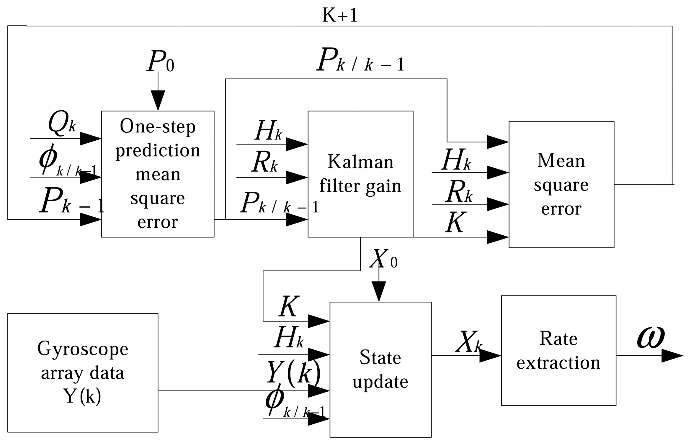
In this paper we took three gyroscopes to form the sensor array. In order to improve the accuracy we treated the true angular rate ω as the state of filtering, which was not equal to zero and was modeled as the random walk driven by the white noise nω whose variance is Qω. Taking the Kalman filtering method [12], the state equations and measurement equations of first-level Kalman filter were established as following.
In Equation (2), X(t) is the state vector, which consists of four components: the first three components are the gyroscope drift rate bias of three gyroscopes respectively, and the four component is the true angular rate. Both w(t) and v(t) are white noise that represents process noise and measurement noise respectively [13,14]. According to the random noise model of MEMS gyroscope, they were built as w(t) = [nb1,nb2,nb3,nω]T and v(t) = [na1, na2, na3]T, where na1, na2 and na3 are angular random walk of the three gyroscopes. The Kalman filter coefficient matrix F, G, H and are given as following.
After discretion, the Equation (2) could be written as:
where t is the period of the discretion, Wk is the sequence of system driving white noise, and Vk is the measurement white noise sequence. And these two noises meet the requirements shown in Equation (4).
By this the first-level filter for the integrated gyroscope array was established (Figure 6), by which the drift could be reduced within the sensors. Especially potential improvement in drift is much more impressive when the noise between the sensors is correlated, i.e. where the Q and R matrices have off-diagonal elements.
3.3 Second-level integrated optimal filter
In the various application areas of MEMS gyroscopes, there are more external sensors such as the magnetometers and accelerometers for combination with gyroscope signal. The information from external sensors is usually to determine the attitude of the aircraft, but also can be used to improve the accuracy of gyroscope by heterogeneous sensors data fusion. Herein in the second-level filter, the gravitational field and earth magnetic field information obtained from the accelerometers and magnetometers were used to be integrated with output of first-level filter to enhance the accuracy of gyroscope. In order to well describe the establishment of the second-level integrated Kalman filter, it needs to make some definitions as shown in Table 2.
3.3.1 State equations derivation
Based on Euler's rotation theorem, the error quaternion Qe was defined as
in condition of small rotation from the estimated quaternion to true quaternion, where
, and qe1 qe2, qe3 is the second, third and the fourth component of the error attitude quaternion respectively. So the true attitude quaternion Q could be expressed in terms of quaternion multiplication as follows [15, 16].
After differentiation and simplification, Equation (5) was written as:
In Equation (6) the ω represents the true angular rate and the ω̂; is the estimation of ω. Making the definition of Δb = b−b̂ as the estimation error of rate random walk, we got the state equations as:
3.3.2 Measurement equations derivation
The integrated Kalman filter used the information of earth magnetic and gravity field as external calibration from which the random errors of MEMS gyroscope were deduced. According to the attitude quaternion, the error of Direction Cosine Matrix was written as:
where I3×3 was the three-by-three identity matrix and [q⃗e × ] was a skew-dissymmetric matrix composed of the components of q⃗e.
Direction Cosine Matrix from b frame to n frame could be written as follows:
In Equation (9), b′ and b represent the computed body frame and true body frame, respectively. The matrix
represents a small angular rotation between b′ and b. Making use of equations (8) and (9), we obtained:
We defined m⃗b and m⃗n as the measurement values of Earth magnetic field in b frame and in n frame respectively [17, 18]. According to the coordinate transformation matrix, they met the following equation:
Then the measurement residual of magnetometer in b frame was defined as follows:
If the similar deduction was carried out for the measurement residual of accelerometer, then the following linear measurement equation was obtained:
So the measurement vector was established as:
3.3.3 Integrated optimal filter design
The error quaternion and estimation error of rate random walk were defined as the state vectors. According to the state and measurement equations established above, the Kalman filter was established as following by using equations (7) and (14):
The Kalman filter coefficient matrix F,G and H were given below.
4. Experimental
4.1 Experiment setup
We took three separate MEMS gyroscopes with identical specifications to form a gyroscope array because the gyroscope array as shown in the Figure 2 has so far been hard to accomplish. Theoretically there should be no correlation between these three sensors, but to verify the proposed accuracy improving method, we assume there is a correlation factor between them. Herein three MEMS gyroscopes with a bias drift of 35 degree per hour were combined to test the proposed integrated gyroscope array method. The bandwidth of gyroscope was 40 Hz and the sampling rate of the gyroscope was at 200 Hz. Then every two hundred sample points were averaged to form a new sample sequence at one point per second. The new sequence was used for the Allan analysis to get the ARW noise matrix Qa, RRW noise Qb, system noise covariance matrix Qk and the measurement noise covariance matrix Rk sequentially. And the measurement values and the above matrix could be fed into the first-level optimal filter.
In the second-level integrated Kalman filter, the outputs of magnetometer and accelerometer were used to feed into the Kalman filter to correct the drifts of gyroscope which were the outputs of first-level Kalman filter. The ARW noise matrix Qa and RRW noise matrix Qb were also established based on analysis of Allan variance. And the measurement values of magnetometer have been compensated for the corresponding error such as magnetic deviation [19].
4.2 Experiment results
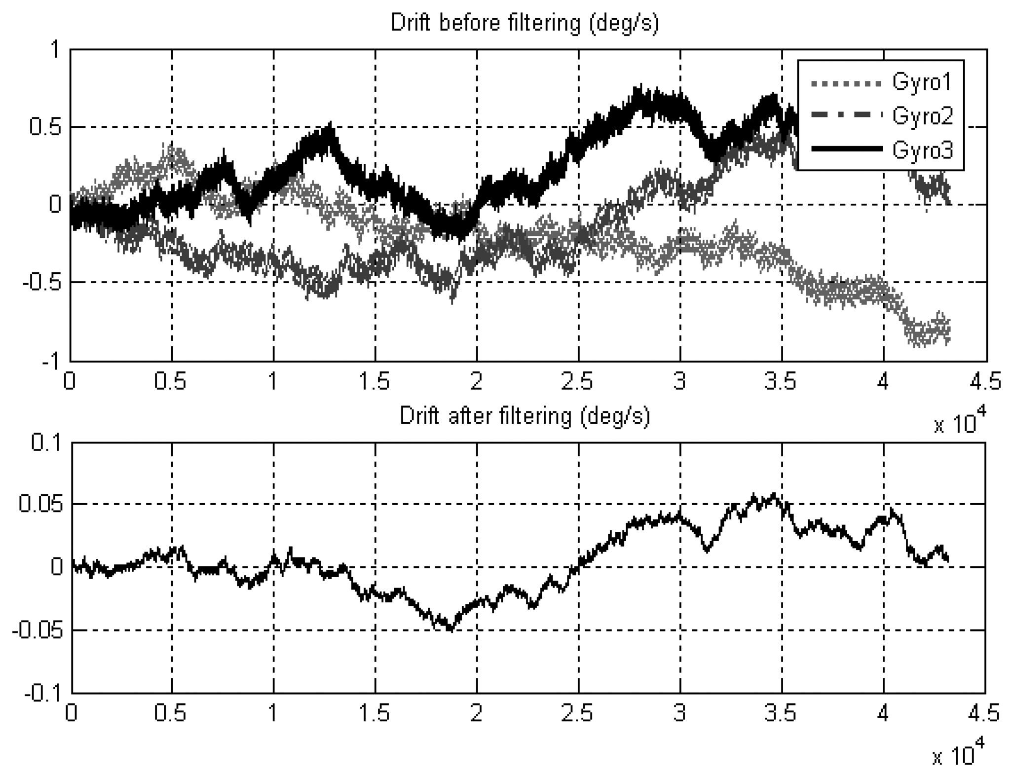
Three gyroscopes with same specifications were used for the first-level optimal filtering. When the correlation factor is set about 0.5, the bias drift of three MEMS gyroscopes with lower accuracy of 35 degree per hour was improved to 1.07 degree per hour by the first-level self compensation in the gyroscope array (Figure 7).
The direct comparison with virtual gyroscope method would be useful to verify the proposed method in addition to the experiment. However such direct comparison is not possible because of the difficulty to attain the same group of drift data to compare both methods. Therefore the verification in the paper was only implemented through such experiment.
Furthermore, the drift was improved to a better degree of about 0.53 degree per hour (Figure 8) after the second-level filtering. In the second-level optimal Kalman filter, the measurement noises of magnetometer and accelerometer are assumed as white noises.
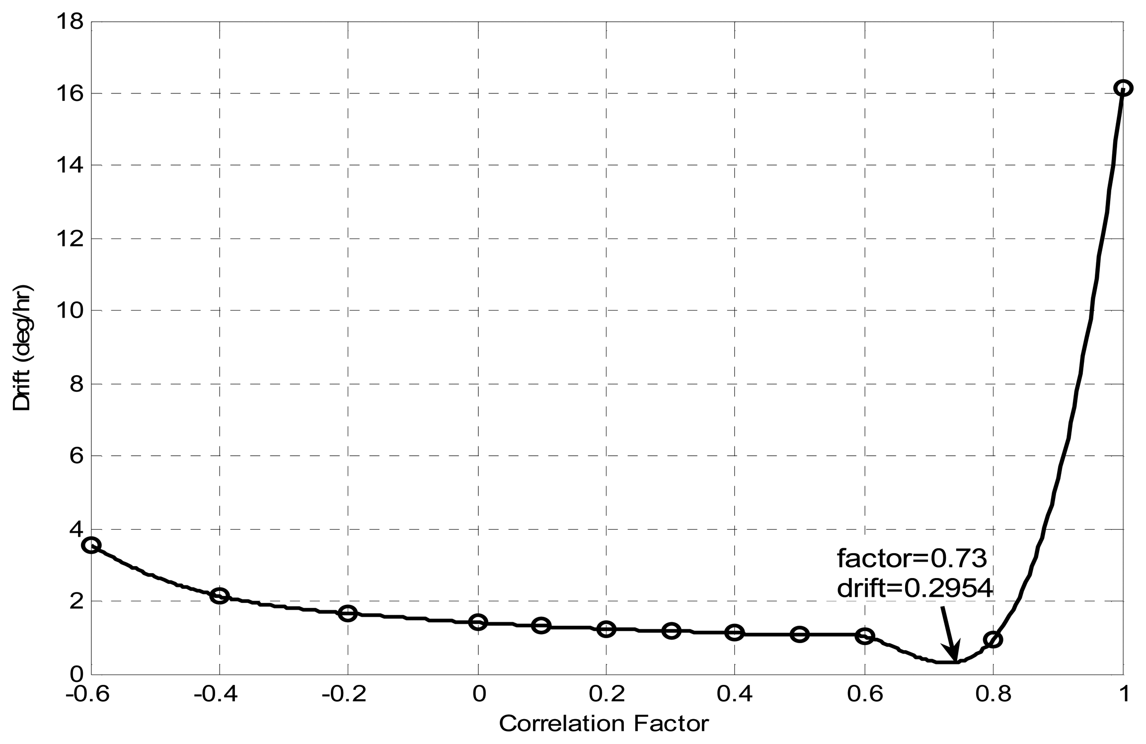
The correlation factor plays an important role in this integrated MEMS gyroscope array method. As shown in Figure 9, the drift reduction varies with correlation factor. Under the conditions presented in this paper, the minimum drift was achieved when the correlation factor is about 0.73. However, we also noted that the drift did not reduce after the filtering but increased when the correlation factor is about minus 0.73, the reason of which may lied in the mismatch of the correlation factor with the filter. Therefore actual implementation of this integrated MEMS gyroscope array needs the adjustment of first-level filter according to the real correlation factor.
5. Conclusions
In this paper an integrated MEMS gyroscope array method to improve the accuracy of MEMS sensors was presented. Contrasted with conventional methods for improving the accuracy of MEMS gyroscopes, which focused on the improvements on interface circuitry or mechanical sensing scheme, the method proposed here enhanced the accuracy from the view of algorithm design approach. Through experiment results, it was proven that the proposed method is very effective at improving the accuracy of MEMS sensors. The first-level optimal filter is very effective for improving the accuracy through homogeneous sensors data fusion within the identical sensors array. The accuracy improvement largely depends on the correlation between the sensors. How to obtain the real correlation factor in the sensor array is a main problem in the implementation of this method. The second-level integral optimal filter can improve the accuracy of the gyroscope further through heterogeneous sensors data fusion techniques.
In the future fabrication of the MEMS gyroscope array on a single chip and the achievement of online correlation factor and filtering would provide a real smart high accuracy angular rate sensor. On the other hand, the measurement random noises of external sensors can be set as a part of the estimator states to get higher accuracy.
Acknowledgments
The authors gratefully acknowledge Chinese National Science Foundation's financial support (Contract No. 50505038) and Chinese Hi-Tech Research and Development Program's financial support (Contract No.2006AA04Z306).
References and Notes
- Weinberg, M.S.; Kourepenis, A. Error sources in in-plane silicon tuning-fork MEMS gyroscopes. Journal of Microelectromechanical Systems 2006, 15, 479–491. [Google Scholar]
- Barbour, N.; Schmidt, G. Inertial Sensor Technology Trends. Proceedings of IEEE Workshop on Autonomous Underwater Vehicles, Cambridge, MA, August 1998; pp. 55–62.
- Lam, Q.M.; Wilson, T., Jr.; Contillo, R.; Buck, D. Enhancing MEMS sensors accuracy via random noise characterization and calibration. Proceedings of SPIE 2004, 5403, 427–438. [Google Scholar]
- Weis, M.; Allan, D. Smart Clock: A New Time. IEEE Transactions on Instrumentation and Measurement 1992, 41, 915–918. [Google Scholar]
- Bayard, D.S.; Ploen, S.R. High accuracy inertial sensors from inexpensive components. US Patent. US20030187623A1, 2003. [Google Scholar]
- Lam, Q.M.; Stamatakos, N.; Woodruff, C.; Ashton, S. Gyro modeling and estimation of its random noise sources. In AIAA Guidance, Navigation, and Control Conference and Exhibit; Austin, Texas, 2003; Volume 5562, pp. 1–11. [Google Scholar]
- Lam, Q.M.; Hunt, T.; Sanneman, P.; Underwood, S. Analysis and design of a fifteen state stellar inertial attitude determination system. In AIAA Guidance, Navigation, and Control Conference and Exhibit; Austin, Texas, 2003; Volume 5483, pp. 11–14. [Google Scholar]
- Kim, S.; Lee, B.; Lee, J. A gyroscope array with linked-beam structure. The 14th IEEE International Conference on Micro Electro Mechanical Systems, January 2001; pp. 30–33.
- Cardarelli, D. An integrated MEMS inertial measurement unit. IEEE Position Location and Navigation Symposium; 2002; pp. 314–319. [Google Scholar]
- Hou, H.; El-Sheimy, N. Inertial sensors errors modeling using Allan variance. Proc. ION GPS/GNSS 2003, 2860–2867. [Google Scholar]
- IEEE standard specification format guide and test procedure for single-axis laser gyros. IEEE Standard 1995, 647–1995.
- Grewal, M.S.; Andrews, A.P. Kalman filtering theory and practice using Matlab; John Wiley & Sons: New York, 2001. [Google Scholar]
- Doob, J.L. Stochastic Processes; John Wiley & Sons: New York, 1953. [Google Scholar]
- Hernandez, W. Robust multivariable estimation of the relevant information coming from a wheel speed sensor and an accelerometer embedded in a car under performance tests. Sensors 2005, 5, 488–508. [Google Scholar]
- Gebre-Egziabher, D.; Gabriel, H. A gyro-free quaternion-based attitude determination system suitable for implementation using low cost sensors. IEEE Position Location and Navigation Symposium 2000, 185–192. [Google Scholar]
- Gebre-Egziabher, D.; Hayward, R.C.; Powell, J.D. Design of multi-sensor attitude determination systems. IEEE Transaction on Aerospace and Electronic System 2004, 40, 627–649. [Google Scholar]
- Su, K.; Ren, D.H.; You, Z.; Zhou, Q. Application of MIMU/Magnetometer Integrated System on the Attitude Determination of Micro Satellite. Proceedings of the 2004 International Conference on intelligent Mechatronics and Automation, Chengdu, China; 2004. [Google Scholar]
- Rong, Z.; Zhaoying, Z. A MEMS-based attitude reference system. Measurement and Control Technology 2002, 21, 6–8. [Google Scholar]
- Caruso, M.J. Application of magneto resistive sensors in navigation systems. Sensors and Actuators 1997, 42, 15–21. [Google Scholar]
Figure 1.
Normalized drift of a four component virtual gyroscope versus different correlation factor.
Figure 1.
Normalized drift of a four component virtual gyroscope versus different correlation factor.

Figure 2.
Schematic of single-chip gyroscope array.
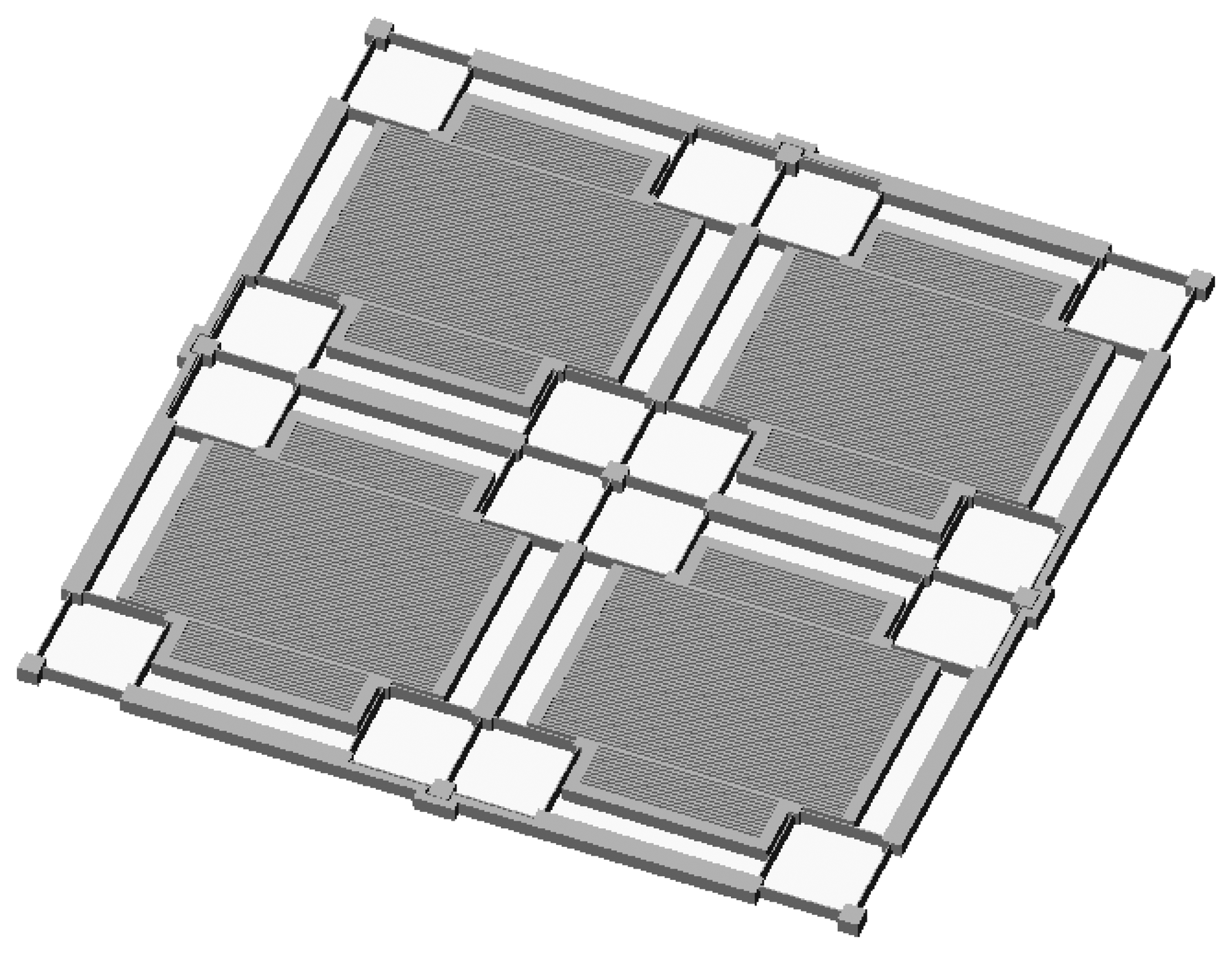
Figure 3.
Structure of the proposed integrated gyroscope array method.
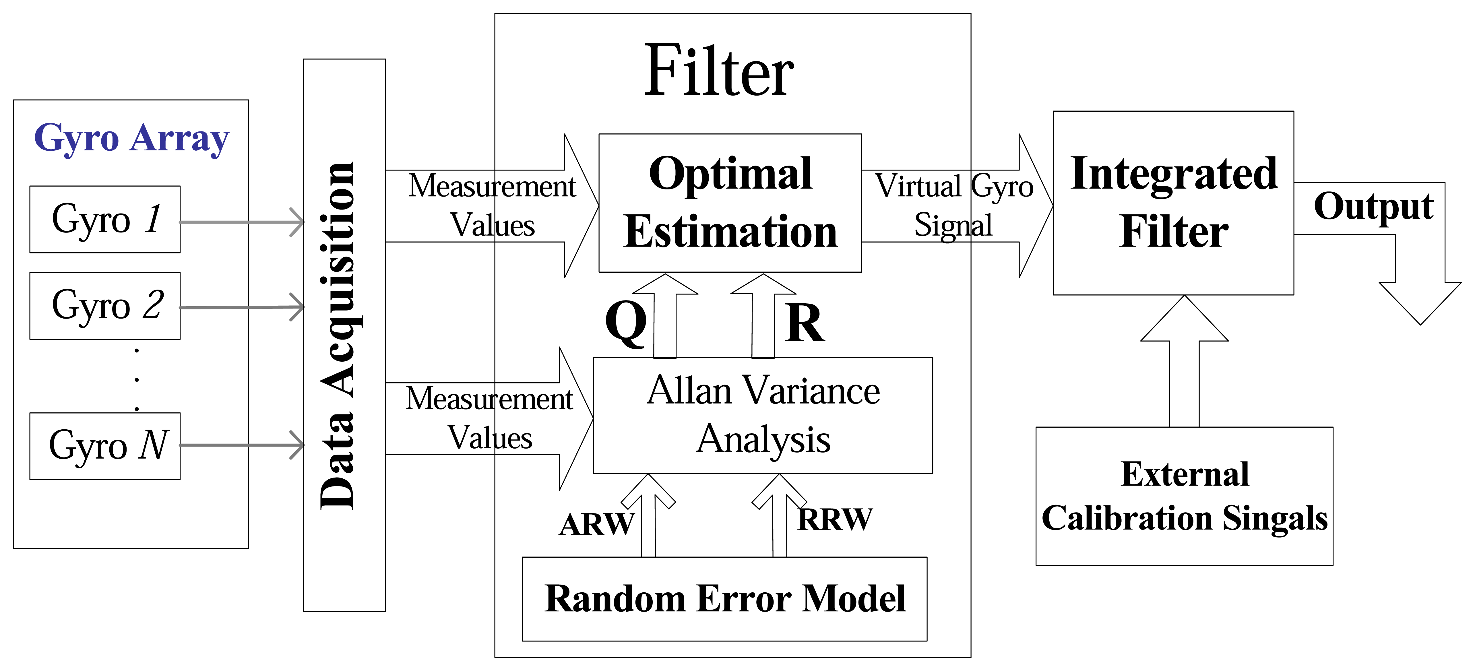
Figure 4.
Random error model with unit scaling for the MEMS gyroscope.
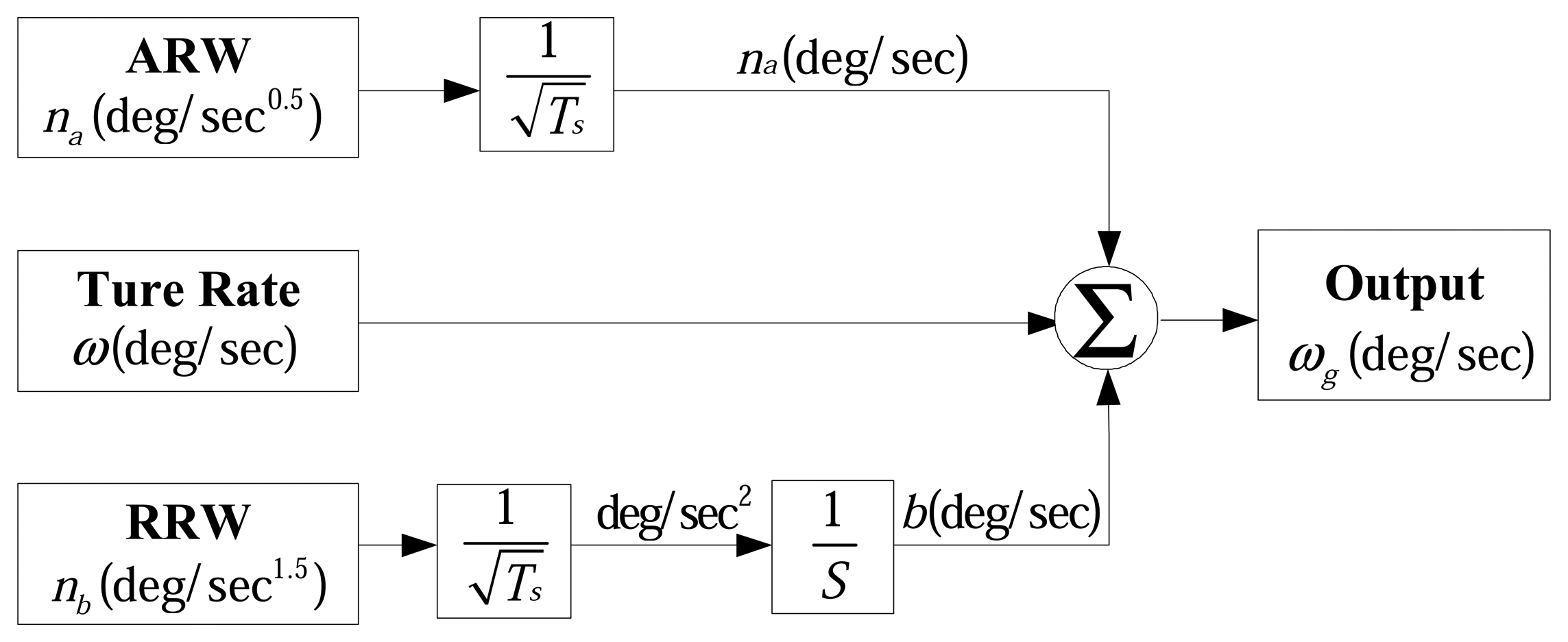
Figure 5.
Allan variance plot of three gyroscopes' bias drift.

Figure 6.
Principle block diagram of first-level Kalman filter.

Figure 7.
Improvements of the bias drift through first-level filtering of gyroscope array.

Figure 8.
Improvement of the bias drift through second-level integrated filtering.
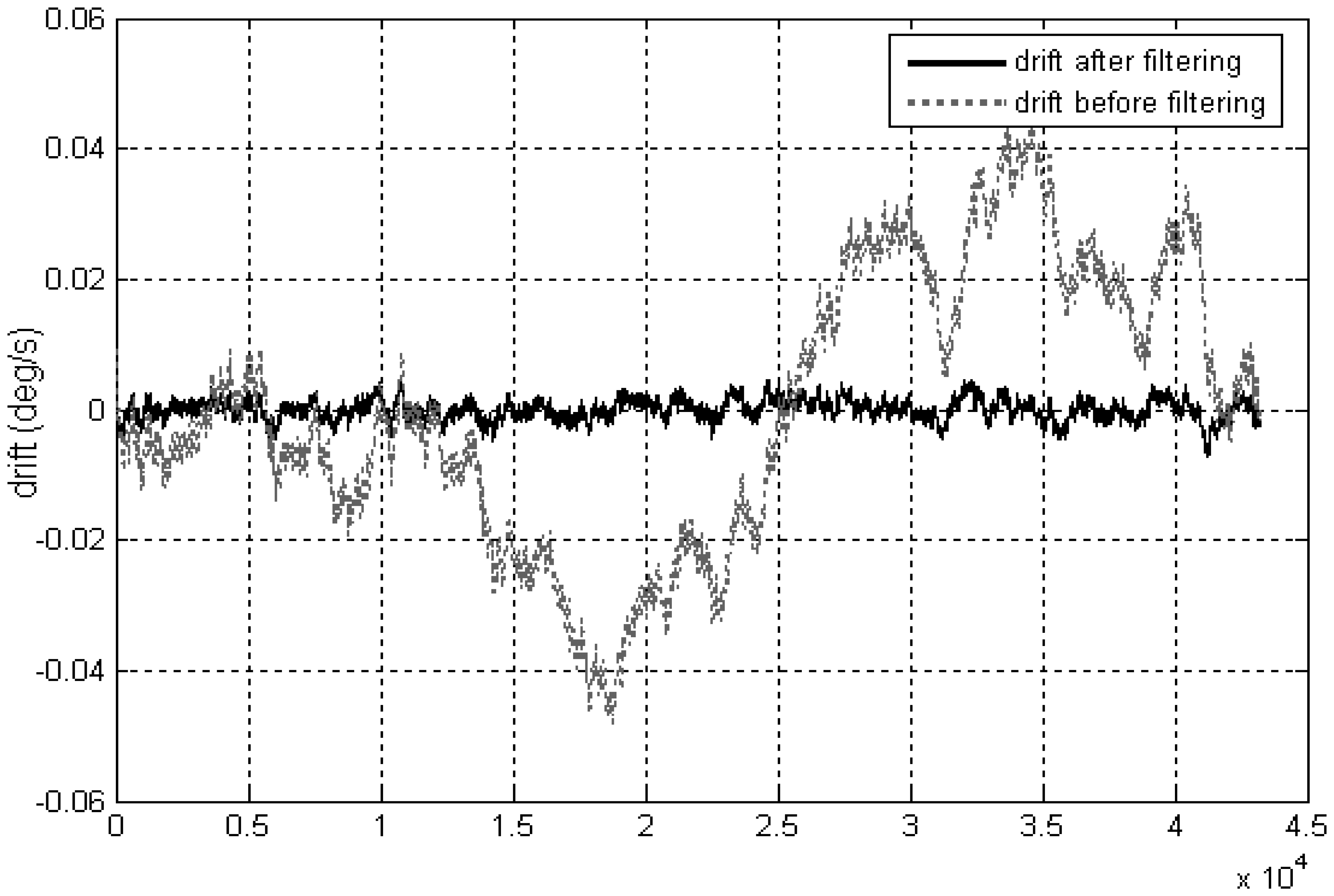
Figure 9.
Plot of drift reduction versus different correlation factor

| Error terms | Allan variance | Unit | Slope |
|---|---|---|---|
| ARW | -1/2 | ||
| Bias Instability | deg/ hr | 0 | |
| RRW | deg/ hr1.5 | +1/2 |
| Symbols | Description |
|---|---|
| b | Body frame of aircraft |
| n | Navigation frame |
| Q | Attitude quaternion |
| Qe | Attitude error quaternion |
| Direction Cosine Matrix (DCM) | |
| m | Measurement value of Earth magnetic |
| a | Measurement value of gravity field |
| b̂ | Estimation of rate random walk |
© 2008 by MDPI (http://www.mdpi.org). Reproduction is permitted for noncommercial purposes.
Share and Cite
MDPI and ACS Style
Chang, H.; Xue, L.; Qin, W.; Yuan, G.; Yuan, W. An Integrated MEMS Gyroscope Array with Higher Accuracy Output. Sensors 2008, 8, 2886-2899. https://doi.org/10.3390/s8042886
AMA Style
Chang H, Xue L, Qin W, Yuan G, Yuan W. An Integrated MEMS Gyroscope Array with Higher Accuracy Output. Sensors. 2008; 8(4):2886-2899. https://doi.org/10.3390/s8042886
Chicago/Turabian StyleChang, Honglong, Liang Xue, Wei Qin, Guangmin Yuan, and Weizheng Yuan. 2008. "An Integrated MEMS Gyroscope Array with Higher Accuracy Output" Sensors 8, no. 4: 2886-2899. https://doi.org/10.3390/s8042886