Precise 3D Lug Pose Detection Sensor for Automatic Robot Welding Using a Structured-Light Vision System

Abstract
:
1. Introduction
2. Automatic Robot Welding System with a 3D Lug Pose Detection Sensor
2.1. Automatic Robot Welding Procedure
2.2. 3D Lug Pose Sensor Design
3. 3D Lug Pose Detection
3.1. Rough Lug Pose Detection
3.2. Precise Welding Line Detection
4. Experimental Results and Discussion
5. Conclusions
Acknowledgments
References and Notes
- Sicard, P.; Levine, M.D. An approach to an expert robot welding system. IEEE Trans. Syst. Man. Cybern 1988, 18, 204–222. [Google Scholar]
- Pires, J.N.; Loureiro, A.; Godinho, T.; Ferreira, P.; Fernando, B.; Morgado, J. Welding robots. IEEE Robot. Automat 2003, 10, 45–55. [Google Scholar]
- Kim, J.S.; Son, Y.T.; Cho, H.S. A Robust Method for Vision-Based Seam Tracking in Robotic Arc Welding. Proceedings of The 10th IEEE International Symposium on Intelligent Control, Monterey, CA, USA, 1995; pp. 363–368.
- Haug, K.; Pristrchow, G. Robust Laser Stripe Sensor for The Automated Weld Seam Tracking in the Shipbuilding Industry. Proceedings of IECON’98 Proceedings of the 24th Annual Conference of the IEEE Industry Electronics Society, Aachen, Germany, 1998; pp. 1236–1241.
- Kim, C.H.; Choi, T.Y.; Lee, J.J.; Suh, J.; Park, K.T.; Kang, H.S. Development of welding profile measuring system with vision sensor. IEEE Sensors 2006, 392–395. [Google Scholar] [CrossRef]
- Kim, C.H.; Choi, T.Y.; Lee, J.J.; Suh, J.; Park, K.T.; Kang, H.S. Intelligent Vision Sensor for the Robotic Laser Welding. Proceedings of IEEE International Conference on Industrial Informatics, Glasgow, UK, 2008; pp. 406–411.
- Lin, X.; Maoyong, C; haixia, W.; Michael, C. A Method to Locate Initial Welding Position of Container Reinforcing Plates using Structured-Light. Proceedings of the 27th Chinese Control Conference, Kunming, Yunnan, China, 2008; pp. 310–314.
- Xu, L.; Cao, M.Y.; Wang, H.X.; Sun, N. Location of Initial Welding Position Based on Structured-light and Fixed in Workspace Vision. Proceedings of IEEE International Conference on Multisensor Fusion and Integration for Intelligent Systems, Seoul, Korea, 2008; pp. 588–592.
- Park, J.B.; Lee, B.H. Supervisory Control for Turnover Prevention of A Teleoperated Mobile Agent with A Terrain-prediction Sensor Module. In Mobile Robots, Moving Intelligence; ARS: Linz, Austria, 2006; pp. 1–28. [Google Scholar]
- Zhang, T.Y.; Suen, C.Y. A fast parallel algorithm for thinning digital patterns. Commun. ACM 1984, 27, 236–239. [Google Scholar]
- Jain, R.; Kasturi, R.; Schunck, B.G. Machine Vision; McGraw-Hill Science: New York, NY, USA, 1995. [Google Scholar]
- Camera Calibration Toolbox for Matlab. Available online: http://www.vision.caltech.edu/bouguetj/calib_doc (accessed on September 22, 2009).


| Procedure: automatic robot welding |
|---|
|
| Sensor Parameters | Descriptions |
|---|---|
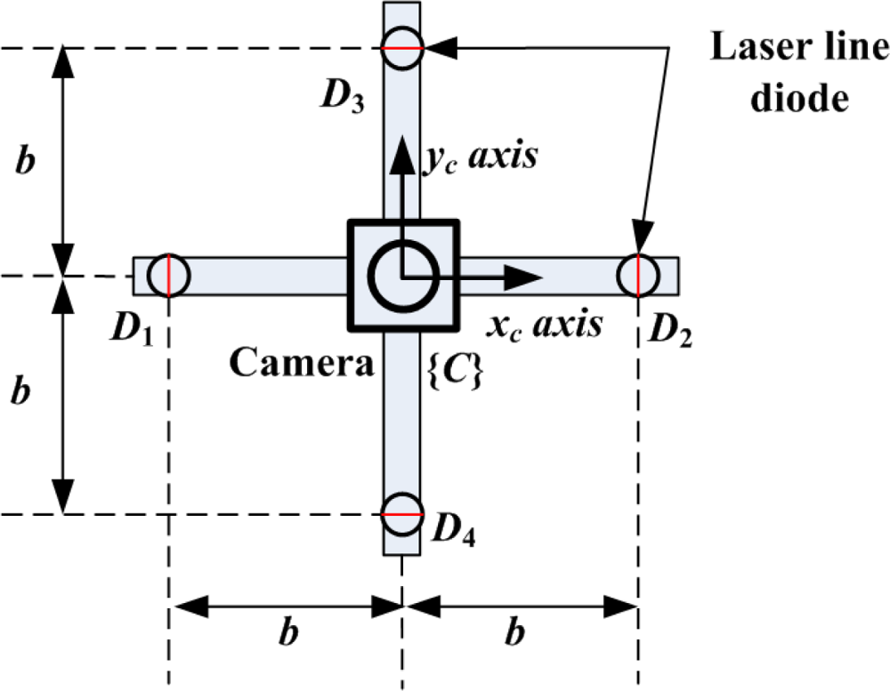
| b = 7 cm | Baseline between the camera and each laser line diode |
| α = 70° | Projection angle of diodes, L1 and L2 |
| β = 96.5° | Projection angle of diodes, L3 and L4 |
| ε1 = 5 pixels | Acceptable boundary of the line parameter ρ for the same line |
| ε2 = 5° | Acceptable boundary of the line parameter θ for the same line |
| xl | 0 | −1 | −2 | −3 | −4 | −5 | −6 | −7 | −8 | −9 | −10 |
| zl | −10.3 | −11.3 | −12.4 | −13.4 | −14.4 | −15.5 | −16.5 | −17.6 | −18.6 | −19.7 | −20.7 |
| xl | −12 | −13 | −14 | −15 | −16 | −17 | −18 | −19 | −20 | −21 | −22 |
| zl | −22.8 | −23.8 | −24.8 | −25.9 | −26.9 | −27.9 | −28.9 | −30.0 | −31.0 | −31.3 | −31.5 |
| xl | −24 | −25 | −26 | −27 | −28 | −29 | −30 | −31 | … | ||
| zl | −32.0 | −32.3 | −32.5 | −32.8 | −33.0 | −33.3 | −33.5 | −33.5 | … |
© 2009 by the authors; licensee MDPI, Basel, Switzerland This article is an open access article distributed under the terms and conditions of the Creative Commons Attribution license (http://creativecommons.org/licenses/by/3.0/).
Share and Cite
Park, J.B.; Lee, S.H.; Lee, I.J. Precise 3D Lug Pose Detection Sensor for Automatic Robot Welding Using a Structured-Light Vision System. Sensors 2009, 9, 7550-7565. https://doi.org/10.3390/s90907550
Park JB, Lee SH, Lee IJ. Precise 3D Lug Pose Detection Sensor for Automatic Robot Welding Using a Structured-Light Vision System. Sensors. 2009; 9(9):7550-7565. https://doi.org/10.3390/s90907550
Chicago/Turabian StylePark, Jae Byung, Seung Hun Lee, and Il Jae Lee. 2009. "Precise 3D Lug Pose Detection Sensor for Automatic Robot Welding Using a Structured-Light Vision System" Sensors 9, no. 9: 7550-7565. https://doi.org/10.3390/s90907550