Article

The Heat Transfer of Microencapsulated Phase Change Material Slurry and Its Thermal Energy Storage Performance of Combined Heat and Power Generating Units

1
Key Laboratory of Condition Monitoring and Control for Power Plant Equipment (North China Electric Power University), Ministry of Education, Beijing 102206, China
2
Northeast Electric Power Design Institute Co., Ltd of China Power Engineering Consulting Group, Changchun 13002, China
*
Author to whom correspondence should be addressed.
Energies 2017, 10(10), 1662; https://doi.org/10.3390/en10101662
Submission received: 10 September 2017 / Revised: 14 October 2017 / Accepted: 16 October 2017 / Published: 20 October 2017

Abstract

:
The application of thermal energy storage (TES) is an effective way of improving the power load regulation capability of combined heat and power (CHP) generating units. In this paper, a theoretical investigation on the thermal energy storage system of a CHP unit that employs the microencapsulated phase change material slurry (MPCMS) as the working fluid is carried out. The results indicate that the microcapsule particle internal melting rate is progressively small; 90% latent heat can be absorbed in 63% total melting time. The melting time of particles in micron is very short, and the diameter is an important factor for microcapsule melting. For the MPCMS flow in a circular tube, the temperature distribution between laminar flows and turbulent flows is different. In a turbulent flow, there is an approximate isothermal section along the tube, which cannot be found in a laminar flow. Additionally, a thermal storage system with MPCMS as heat transfer fluid for a CHP unit is proposed. A case study for a 300 MW CHP unit found that the use of an MPSMS thermal energy storage system increases the power peak shaving capacity by 81.4%. This indicates that the thermal storage system increases the peak shaving capacity of cogeneration units.

1. Introduction

Wind energy technology is one of the most important renewable energy technologies for power generation. With its unique geographical location and rich resources, the wind power industry has recently achieved rapid growth in China [1]. Combined heat and power (CHP) generation technology has recently developed a great deal in North China and this district is abundant in wind power. So during the heating period of winter, there is a serious conflict of electric power loads between that of wind power plants and CHP plants [2,3,4]. In order to overcome this problem, there is an urgent demand for increasing the power load regulation capability of CHP units.
Microencapsulated phase change material slurry (MPCMS) is the mixture of microencapsulated phase change material (MPCM) particles and a single-phase fluid. It is a micro ball with a strong shell and phase change material (PCM) as its core. Usually, the shell consists of polymer materials, and the core material consists of paraffin and fatty acid. The ball diameter is 10~100 μm, which ensures physical stability. There have been numerous investigations, theoretical and experimental, of MPCMS due to its excellent performance in heat transfer and thermal energy storage [5,6,7,8,9,10,11,12,13]. The application of MPCMS in thermal energy storage has also attracted attention in recent years. Wang et al. [14] proposed an air conditioning system that combined evaporative cooling, MPCMS storage, and chilled celling. Qiu et al. [15] used MPCMS to theoretically investigate a PV/T module. Griffiths and Eames [16] applied BASF (Badische Anilin-und-Soda-Fabrik) MPCMS with a melt temperature of 18 °C to a chilled ceiling of a test chamber. Wang and Niu [17] investigated the performance of a new air conditioning system comprised of the chilled ceilings and the MPCMS storage tank using Hong Kong’s weather data and hexadecane (C16H34) capsules as the PCM chemical. Huang et al. [18] developed a test system that was configured as a traditional hot water storage cylinder and used to examine the performance of MPCMS in residential thermal energy storage applications.
A literature review indicated that, despite former studies regarding MPCMS focused on the small-scale thermal energy storage, the potential application of the MPCMS for improving the thermal storgae capacity has been verified. However, there are few studies that combine heat transfer and thermodynamics to analyze the peaking capacity of CHP units. In this paper, the feasibility of using MPCMS as a thermal energy storage medium in a large-scale CHP unit is theoretically investigated. It is shown herewith that the regulation capability of a CHP unit can be improved to assure that more wind power can be accepted by an electric power system in winter. The unit’s thermal physical characteristics, as well as its flow and heat transfer performances in a tube, have been discussed in detail.

2. Thermal Physical Characteristics of the Selected MPCMS

Hentetracontane is a chemically stable phase change material (PCM) that can retain the steady thermal performance after numerous thermal cycles. Additionally, its melting point matches well with the thermal storage system requested by the heating temperature of a CHP unit. Thus, this material was selected and made into the microencapsulated structure. Water was used as the carrier fluid. The thermal and physical properties of this MPCMS are shown in Table 1.
Flow and heat transfer characteristics are associated with the following independent properties: density, viscosity, thermal conductivity, melting/freezing temperature, and the heat of fusion. For the MPCMS, its density and specific heat were calculated using the mass fractions of the PCM, the shell material, and the water, respectively, based on the mass and energy balance [12]:
ρ p = ρ p , c ( 1 c m ) + ρ p , w c m
ρ b = ρ f ( 1 c ) + ρ p c
c p , p = c m c p , c + ( 1 c m ) c p , s
c p , b = c c p , p + ( 1 c ) c p , f
where ρ p in kg/m3 is the density of a single MPCM particle, ρ p , c in kg/m3 is the density of the MPCM particle core material, ρ p , w is the density of the MPCM shell material, ρ b is the density of the MPCMS, ρ f is the density of the carrier fluid, cm in % is the core material concentration, and c in % is the MPCM particle concentration.
The thermal conductivity of the MPCM particle can be acquired based on the composite sphere approach [13]:
1 k p d p = 1 k p c d p c + d p d p c k p d p d p c .
In the present analysis, the thermal conductivity of the slurry was then obtained with Maxwell’s relation:
k b k f = 2 + k p k f + 2 c ( k p k f 1 ) 2 + k p k f c ( k p k f 1 )
where k b is the conductivity of the MPCMS, W / m K ; k f is the conductivity of the carrier fluid, W / m K ; k p is the conductivity of an MPCM particle, W / m K ; k p c is the conductivity of the core material, W / m K ; d p and d p c are the diameters of an MPCM particle and the core material, in m.
As for the viscosity, the Vand viscosity equation is employed [19], which is shown as:
μ b μ f = ( 1 c 1.16 c 2 ) 2.5
where μ b is the viscosity of the MPCMS, N s / m 2 ; μ f is the viscosity of the carrier fluid, N s / m 2 ; c is the particle concentration.

3. Flow and Heat Transfer for MPCMS

To obtain the heat transfer characteristics of the MPCMS, an equivalent specific heat model was carried out. An equivalent specific heat model is a simplified simulation model for MPCMS. Its purpose is to make the heat transfer enhancement of the MPCM equivalent to the specific heat of the MPCMS. In order to explain the consistency of the equivalent specific heat model, the simulation of a single MPCM particle was first proposed.

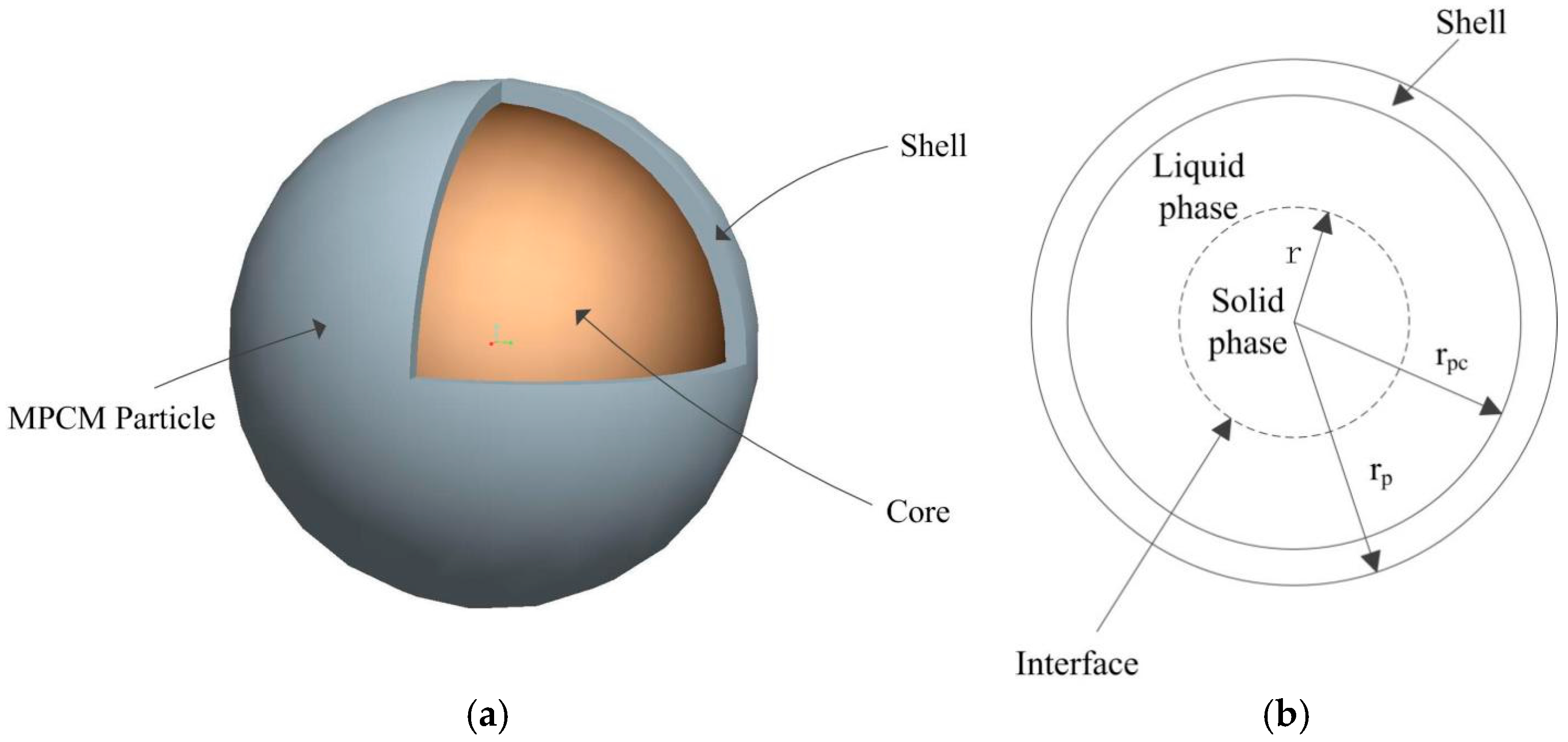
3.1. Simulation for Single MPCM Particle

The simulation was focused in the melting process of a single MPCM particle as shown in Figure 1a. An enthalpy model was proposed and developed to analyze the melting process. Considering the MPCM particle as a small ball, the melting process is shown in Figure 1b.
The energy equation can be written as:
t ( ρ H ) + ( ρ V H ) = ( k T ) + S
where H is the enthalpy, J/g; T is the temperature, K; S is the source term; V is the velocity, m/s.
The relationship between enthalpy H and temperature T is as follows:
H = h + Δ h
h = h r e f + T r e f T c p d T

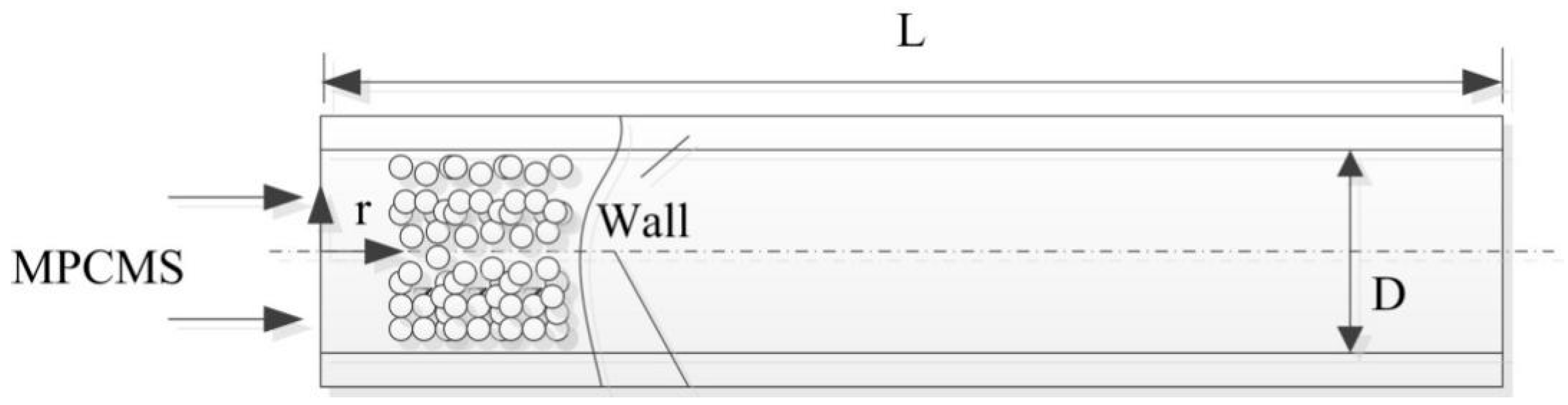
3.2. Simulation for MPCMS

To obtain the heat transfer characteristics of MPCMS, a simulation of MPCMS flowing in a circular tube was carried out. A schematic is shown in Figure 2. The following assumptions are made to simplify the heat transfer model:
(1)
The fluid can be considered as a Newtonian fluid.
(2)
The MPCM particles are uniformly distributed in the slurry.
(3)
The viscous dissipation and axial heat conduction can be ignored.
(4)
The no-slip condition is considered.
(5)
The interfacial thermal resistance for MPCM particles is too small to be neglected.
The energy equation for the MPCMS can be written as:
ρ b c p , b ( u T x + v r T r ) = 1 r r ( r k e T r ) .
The flow equations for the MPCMS are shown as follows:
u x + 1 r r ( r v r ) = 0
{ ρ b u u x + ρ b v r u r = P x + μ b [ 1 r r ( r u r ) + 2 u x 2 ] ρ b u v r x + ρ b v r u r = P x + μ b [ 1 r r [ r r ( r v r ) ] + 2 v r x 2 ] .
The boundary conditions are list as follows:
T | x = 0 = T i , T r | r = 0 = 0 , T | r = r d = T w
Section 3.1 supports the simulation in Section 3.2. The purpose of a simulation for the melting process of a single MPCM particle is to determine the heat resistance between the MPCM particle and the carrier fluid. This would prove that the equivalent specific heat model used in Section 3.2 is effective.

4. Results with Discussions

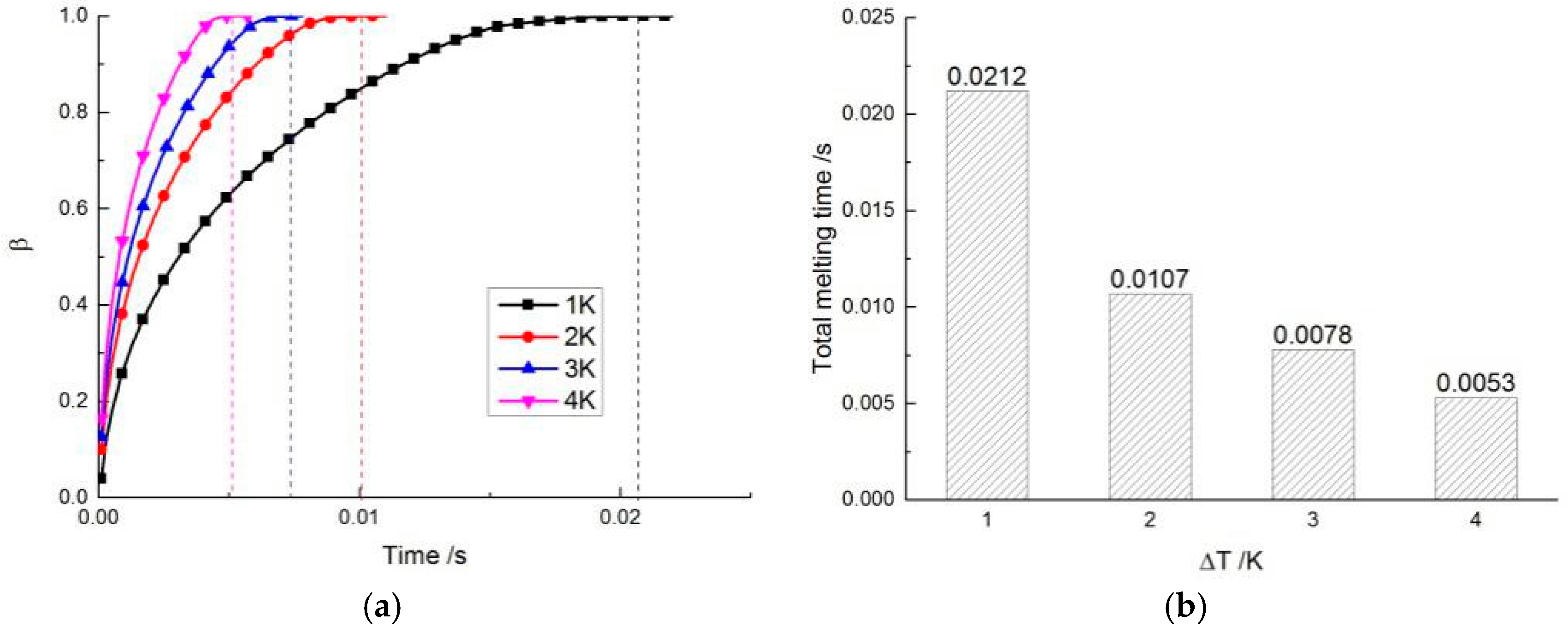
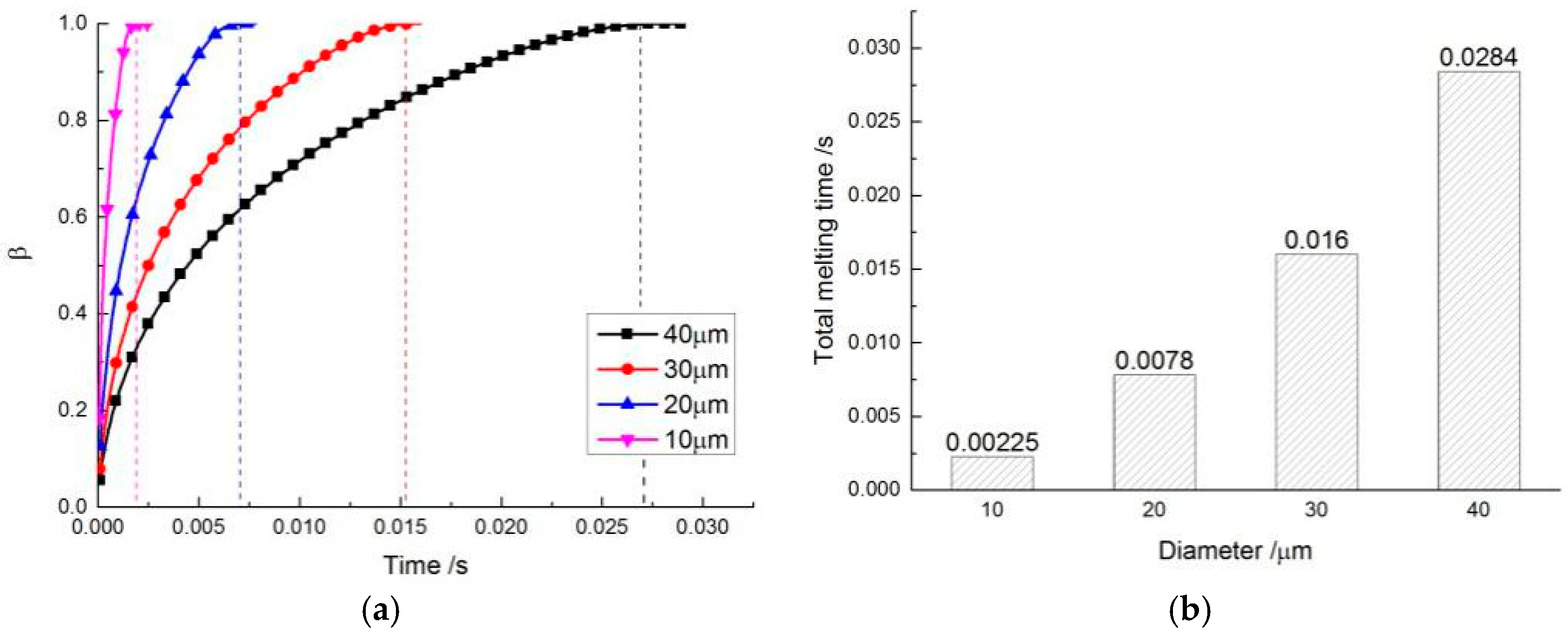
4.1. The Melting Process of a Single MPCM Particle

The melting process of the MPCM particles, whose core material is hentetracontane and wall material is urea resin, is important for the heat transfer of MPCMS. Two factors were considered in the analysis: the diameter, d p , and the wall temperature difference, Δ T :
Δ T = T w a l l T m e l t i n g
where T w a l l is the particle wall surface temperature, K; T m e l t i n g is the melting temperature of PCM, K.
Figure 3 illustrates the particle melting process at different diameters d p , while the wall temperature difference Δ T is constant. The β on y represents the melting process of the MPCM particle. It can be concluded that the diameter is an important factor in determining melting time. The melting time of d p = 40   μ m is 1.8 times greater than d p = 30   μ m and 12.6 greater than d p = 10   μ m . The Figure 3 also indicate that the melting time is very short. The results indicate that the microcapsule particle’s internal melting rate is progressively small; 90% PCM has melted in 63% total melting time and the last 10% need cost 37% total melting time to melt completely. Figure 4 shows the particle melting process at different wall temperatures, while the diameter d p is constant. As the wall temperature increases, the total melting time becomes shorter and shorter. Raising Δ T cannot always achieve obvious improvement when Δ T is high enough. The melting rate does not increase linearly as Δ T rising. Above all, for a single MPCM particle, the total melting time is very short, which indicates that the thermal resistance between the carrier fluid and the MPCM particle is very small. This proves that the equivalent specific heat model is effective.

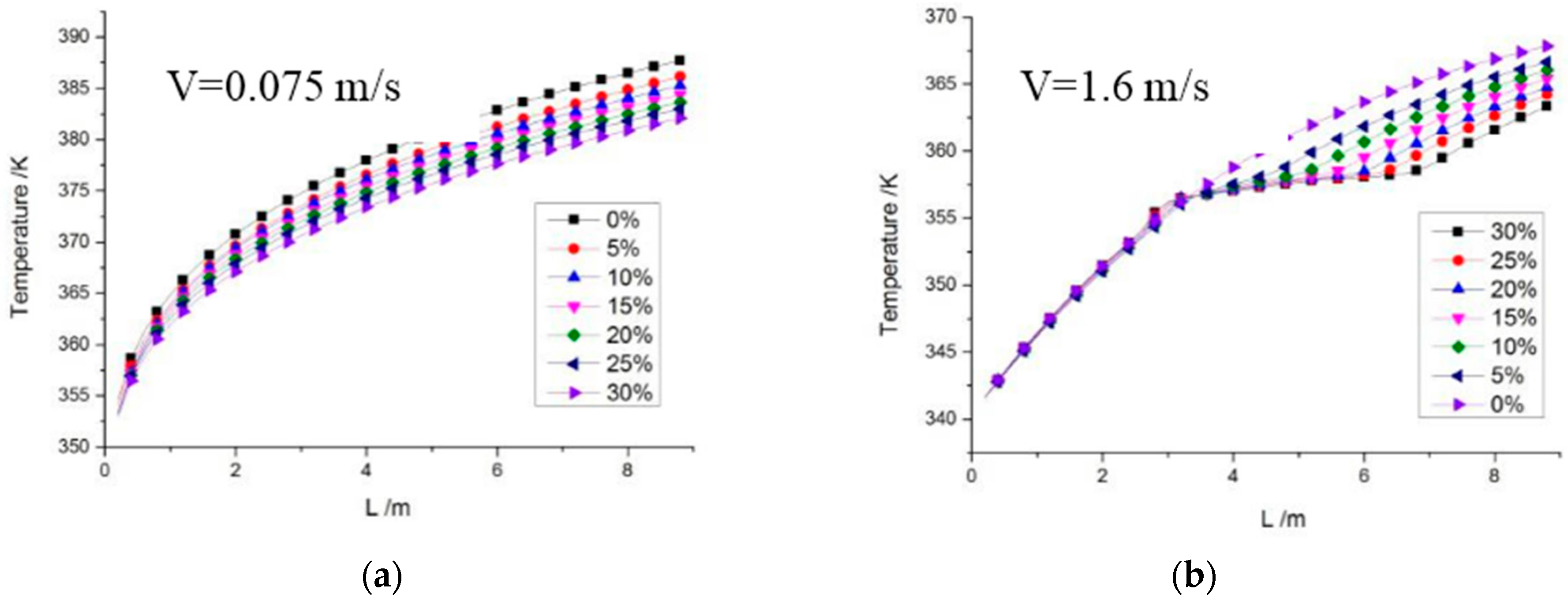
4.2. MPCMS Heat Transfer in Circular Tube

In order to obtain the heat transfer characteristics of MPCMS, a CFD simulation is proposed in a long aluminum tube with a length of 9 m, and a diameter of 0.018 m. Using an equivalent specific heat model, both the laminar flow and the turbulent flow were considered.
Figure 5a shows the temperature distribution along the tube under a laminar flow at different MPCM concentrations. As the concentration increases from 0 to 30%, the temperature along the tube decreases. However, there was no apparent isothermal process. Our analysis indicated that, in a laminar flow condition, the heat gradually transferred from the wall to the center of the tube. The particles melted and also transferred from the wall to the center. In a turbulent flow, shown in Figure 5b, there was an apparent isothermal process at the melting temperature. This is because in a turbulent flow, the momentum exchanges more perpendicularly to the flow direction.

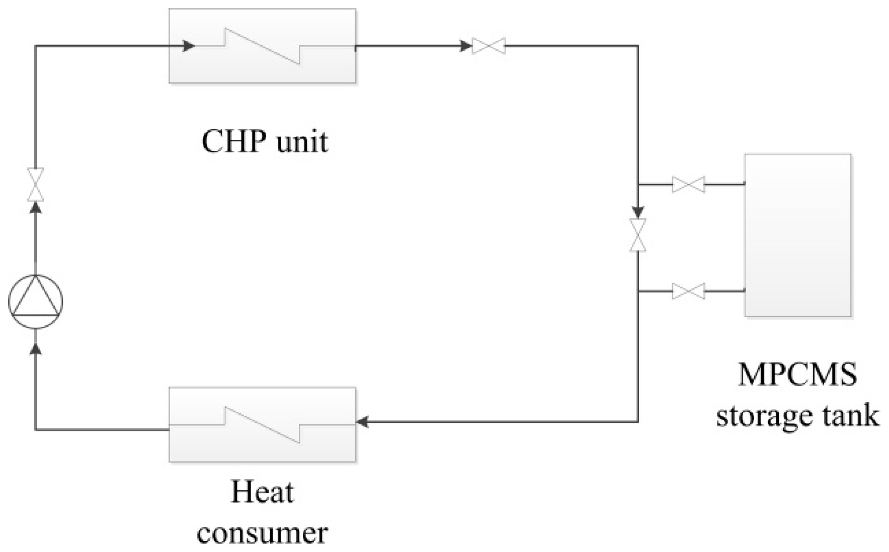
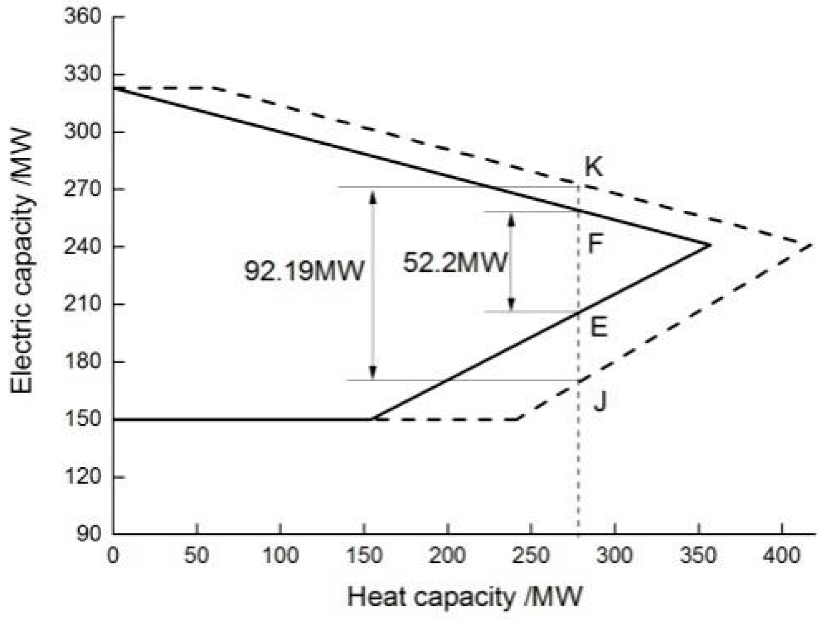
4.3. A 300 MW CHP Unit Case Study

A 300 MW CHP unit with an MPCMS thermal storage system is proposed here. The schematic of the system is shown in Figure 6. The MPCMS storage tank was set between the CHP unit and heat consumer. The system used MPCMS as both the heat transfer fluid and the thermal storage medium. It absorbed the thermal energy from the CHP unit extract steam when the power load was high, and then released it to the heat consumer when the power load was low. Through the thermal storage tank, it increased the peak shaving capacity of the CHP unit.
With the heat calculation method and the Dufort–Frankel scheme, the primary unit’s thermoelectric coupled model can be made when the MPCS is used [20]. The governing equation is shown as:
{ max { P e , min c v 2 P h , P e , min c v 2 P h , m e d , c m ( P h P f , max P 0 ) } P e min { P e , max c v 1 ( P h P f , max ) , P e , max } 0 P h P h , max + P f , max .
The power shaving capacity was calculated at a certain heat load. As shown in Figure 7, as an example, it can be concluded that, at a rated heat load, the peak shaving capacity increases from 52.2 to 92.19 MW with the MPCMS storage system, which is an improvement of 81.4%.

5. Conclusions

A thermal storage system using MPCMS in a CHP unit is proposed. Both the heat transfer characteristics of MPCMS and the peak shaving capacity were considered. The conclusions drawn are as follows.
(1)
The MPCM particle’s total melting time is very short, which indicates that the thermal resistance between the carrier fluid and the MPCM particle is very small. This proves that the equivalent specific heat model used in heat transfer simulations is effective.
(2)
Both the wall temperature and the ball diameter are important factors for the MPCM particle melting process. A ball with a small diameter is ideal in MPCMS. Raising ∆T cannot always achieve obvious improvement when ∆T is high enough. So the wall temperature is recommended to choose in a small range higher than the melting point.
(3)
It was found that the heat transfer characteristics of MPCMS are different depending on whether the heat transfer is in a laminar and a turbulent flow. Only in a turbulent flow condition will there be an isothermal process along the tube. The heat transfer characteristics in a turbulent flow are much greater than those in a laminar flow.
(4)
The research also indicates that thermal storage system increases the peak shaving capacity of cogeneration units. For a 300 MW CHP unit, the peak shaving capacity increases from 52.2 to 92.19 MW, which is an improvement of 81.4%.

Acknowledgments

The financial supports for this research project from the National Natural Science Foundation of China (No. 51676069) and the national “973 Program” of China (No. 2015CB251505) are gratefully acknowledged.

Author Contributions

Xiaoze Du provided the main idea of the study; Yonghong Guo, Xinglong Zhang developed the model and analyzed the data; Lijun Yang and Chao Xu provided language support and revised the paper.

Conflicts of Interest

The authors declare no conflicts of interest.

References

  1. Global Wind Energy Council (GWEC). Global Wind Report 2016-Annual Market Update. 2016. Available online: http://www.gwec.net/publications/global-wind-report-2/global-wind-report-2016-annual-market-update (accessed on 10 September 2017).
  2. Hu, Y.; Huang, W.; Wang, J.; Chen, S.; Zhang, J. Current status, challenges, and perspectives of Sichuan’s renewable energy development in Southwest China. Renew. Sustain. Energy Rev. 2016, 57, 1373–1385. [Google Scholar] [CrossRef]
  3. Luo, G.; Li, Y.; Tang, W.; Wei, X. Wind curtailment of China’s wind power operation: Evolution, causes and solutions. Renew. Sustain. Energy Rev. 2016, 53, 1190–1201. [Google Scholar] [CrossRef]
  4. Fan, X.; Wang, W.; Shi, R.; Li, F. Analysis and countermeasures of wind power curtailment in China. Renew. Sustain. Energy Rev. 2015, 52, 1429–1436. [Google Scholar] [CrossRef]
  5. Delgado, M.; Lázaro, A.; Mazo, J.; Zalba, B. Review on phase change material emulsions and microencapsulated phase change material slurries: Materials, heat transfer studies and applications. Renew. Sustain. Energy Rev. 2012, 16, 253–273. [Google Scholar] [CrossRef]
  6. Stamatiou, E.; Kawaji, M. Thermal and flow behavior of ice slurries in a vertical rectangular channel. Part I: Local distribution measurements in adiabatic flow. Int. J. Heat Mass Transf. 2005, 48, 3527–3543. [Google Scholar] [CrossRef]
  7. Royon, L.; Guiffant, G. Forced convection heat transfer with slurry of phase change material in circular ducts: A phenomenological approach. Energy Convers. Manag. 2008, 49, 928–932. [Google Scholar] [CrossRef]
  8. HE, B.; Martin, V.; Setterwall, F. Phase transition temperature ranges and storage density of paraffin wax phase change materials. Energy 2004, 29, 1785–1804. [Google Scholar] [CrossRef]
  9. Sohn, C.; Chen, M. Microconvective Thermal Conductivity in Disperse Two-Phase Mixtures as Observed in a Low Velocity Couette Flow Experiment. J. Heat Transf. 1981, 103, 47–51. [Google Scholar] [CrossRef]
  10. Charunyakorn, P.; Sengupta, S.; Roy, S. Forced convection heat transfer in microencapsulated phase change material slurries: Flow in circular ducts. Int. J. Heat Mass Transf. 1991, 34, 819–833. [Google Scholar] [CrossRef]
  11. Goel, M.; Roy, S.; Sengupta, S. Laminar forced convection heat transfer in microcapsulated phase change material suspensions. Int. J. Heat Mass Transf. 1994, 37, 593–604. [Google Scholar] [CrossRef]
  12. Yamagishi, Y.; Takeuchi, H.; Pyatenko, A.; Kayukawa, N. Characteristics of microencapsulated PCM slurry as a heat-transfer fluid. AIChE J. 1999, 45, 696–707. [Google Scholar] [CrossRef]
  13. Hu, X.; Zhang, Y. Novel insight and numerical analysis of convective heat transfer enhancement with microencapsulated phase change material slurries: Laminar flow in a circular tube with constant heat flux. Int. J. Heat Mass Transf. 2002, 45, 3163–3172. [Google Scholar] [CrossRef]
  14. Wang, X.; Niu, J. Performance of cooled-ceiling operating with MPCM slurry. Energy Convers. Manag. 2009, 50, 583–591. [Google Scholar] [CrossRef]
  15. Qiu, Z.; Zhao, X.; Li, P.; Zhang, X.; Ali, S.; Tan, J. Theoretical investigation of the energy performance of a novel MPCM (Microencapsulated Phase Change Material) slurry based PV/T module. Energy 2015, 87, 686–698. [Google Scholar] [CrossRef]
  16. Griffiths, P.; Eames, P. Performance of chilled ceiling panels using phase change material slurries as the heat transport medium. Appl. Therm. Eng. 2007, 27, 1756–1760. [Google Scholar] [CrossRef]
  17. Wang, X.; Niu, J.; van Paassen, A. Raising evaporative cooling potentials using combined cooled ceiling and MPCM slurry storage. Energy Build. 2008, 40, 1691–1698. [Google Scholar] [CrossRef]
  18. Huang, M.; Eames, P.; McCormack, S.; Griffiths, P.; Hewitt, N. Microencapsulated phase change slurries for thermal energy storage in a residential solar energy system. Renew. Energy 2011, 36, 2932–2939. [Google Scholar] [CrossRef]
  19. Vand, V. Theory of Viscosity of Concentrated Suspensions. Nature 1945, 155, 364–365. [Google Scholar] [CrossRef]
  20. Tian, C.; Lv, X.; Li, D.; Dong, T.; Han, X. Analysis on Thermal Economy and Peak-Shaving Capability for Combined Heat and Power (CHP) Unit in Varying Operating Conditions. Appl. Mech. Mater. 2014, 521, 508–515. [Google Scholar] [CrossRef]
Figure 1. Schematic of a single microencapsulated phase change material (MPCM) particle melting process. (a) An MPCM particle structure. (b) The phase change inside an MPCM particle.
Energies 10 01662 g001
Figure 2. Schematic of MPCMS in a circular tube flow.
Energies 10 01662 g002
Figure 3. Melting process at different diameters. (a) Melting process; (b) Total melting time.
Energies 10 01662 g003
Figure 4. Melting process at different wall temperatures. (a) Melting process; (b) Total melting time.
Energies 10 01662 g004
Figure 5. Average temperature distribution along the tube. (a) Laminar flow; (b) Turbulent flow.
Energies 10 01662 g005
Figure 6. Schematic of MPCMS storage system.
Energies 10 01662 g006
Figure 7. Peak shaving capacity with MPCMS storage system.
Energies 10 01662 g007
Table 1. Thermal and physical properties of the microencapsulated phase change material slurry (MPCMS).
ParametersCarrier FluidCore MaterialWall Material
MaterialWaterHentetracontaneUrea resin
Density/(kg/m3)9988701420
Specific heat/(J/kg·K)418022001672
Melting point/(°C)-84.1-
Latent heat/(J/g)-262.1-
conductivity/(W/m·K)0.670.210.56

