Application of Confined Blasting in Water-Filled Deep Holes to Control Strong Rock Pressure in Hard Rock Mines

1
Key Laboratory of Deep Coal Resource Mining, Ministry of Education, China University of Mining and Technology, Xuzhou 221116, China
2
Datong Coal Mine Group Co. Ltd., Datong 037000, China
*
Author to whom correspondence should be addressed.
Energies 2017, 10(11), 1874; https://doi.org/10.3390/en10111874
Submission received: 26 September 2017
/
Revised: 6 November 2017
/
Accepted: 13 November 2017
/
Published: 15 November 2017
(This article belongs to the Special Issue Mathematical and Computational Modeling in Geothermal Engineering)
Abstract
:In extra-thick coal seams, mining operations can lead to large-scale disturbances, complex overburden structures, and frequent and strong strata behavior in the stope, which are serious threats to mine safety. This study analyzed the overburden structure and strata behavior and proposed the technique of confined blasting in water-filled deep holes as a measure to prevent strong rock pressure. It found that there are two primary reasons for the high effectiveness of the proposed technique in presplitting hard coal and rock. First, the fracture water enables much more efficient transfer of dynamic load due to its incompressibility. Second, the subsequent expansion of water can further split the rock by compression. A mechanical model was used to reveal how the process of confined blasting in water-filled deep holes presplit roof. Moreover, practical implementation of this technique was found to improve the structure of hard, thick roof and prevent strong rock pressure, demonstrating its effectiveness in roof control.
1. Introduction
In the Datong Coal Mine area, coal is mined from Jurassic and Carboniferous coal seams. As the Jurassic coal is largely depleted, the Carboniferous seams have become the main seams in this area. The Carboniferous extra-thick seams are overlain by multiple thick layers of hard sandy rocks. After coal is cut from these seams, it is allowed to fall into a large space, the overburden shows complex patterns of movement and fracture, and the mining-induced stress extends far and wide [1]. Roof supports and mining roadways in these seams have been damaged to various degrees as a result of frequent occurrence of strong strata behavior and the associated dynamic loading during mining [2]. Relevant research has shown found that the structural evolution and movement of the overburden during mining of the Jurassic and Carboniferous seams is a complex process characterized by separation and cascading movement of strata and interaction between them. Besides, the induced roof weighting has unique characteristics, such as alternate long and short weighting intervals and irregular weighting intensity. Additionally, the use of unsuitable types of supports and ineffective measures for hard roof control has relatively significant impact on the coal extraction in the Datong Coal Mine area [1,2,3]. Over the past decade, Datong Coal Mine Group Co. Ltd (Datong, China) and universities from China and other countries have carried out collaborative research into mechanisms and techniques for controlling the hard roof strata over the Jurassic and Carboniferous coal seams. They have proposed the concept of large space stope and revealed the causes of strong strata behavior in large space stope through field measurements and systematic structural analysis of overburden. It was found that the destabilization and cascading movement of roof strata is the primary trigger for strong strata behavior in large space stope [1,4]. Therefore, the key to dealing with strong rock pressure in large space stope is not to take passive control measures, but rather to prevent it by preconditioning the hard roof in advance.
Rock blasting is widely used in hydraulic engineering, hydropower, mining, transportation, etc., and it has brought huge economic and social benefits [5,6,7,8,9]. However, conventional rock blasting has limited application in coal mines under complex conditions [10,11,12,13]. Research has shown that wave impedance matching between explosive charge in blast holes and the wall rock can help make more efficient use of the high energy released by explosives and thereby enhance blast effects [14,15,16]. By virtue of the incompressibility and inertia of water, hydraulic blasting can provide significantly stronger blast effects than conventional rock blasting which uses normal explosives [17,18,19,20]. However, hydraulic blasting has not been fully accepted or applied in coal mining for several reasons, including its technical complexity, various limitations on the procedure and equipment used in water injection and hole sealing, and large amount of water leakage to coal seams [13,21]. Therefore, there is an urgent need to improve the conventional blasting technique to make it more effective and energy efficient.
The deep-hole confined blasting technique for weakening hard coal and rock uses confined water (or a liquid explosive) as the transmission medium for detonation waves. The confined water can make the fracture fluid better able to transfer dynamic load and overcome the drag associated with its viscosity and capillary action, thereby reducing explosive energy loss. Meanwhile, the presence of water can help guide the explosive shock waves, promote fracture propagation, avoid high temperature, and prevent hazards like sparks. In this technique, the blast-hole loading and sealing procedure is simplified and the explosive in blast holes can presplit hard coal and rock in a safer and more effective manner [22,23,24,25]. In this study, the technique of confined blasting in water-filled deep holes was applied to presplit the thick seam and hard roof in Datong Coal Mine area. Efficient presplitting and effective control of strong rock pressure were achieved, and difficulties in loading deep holes were removed.
2. Overview of Mining in Datong Coal Mine Area
As the Jurassic coal seams in the Datong Coal Mine area are almost fully depleted, the deeper extra-thick Carboniferous age seams are gradually becoming the main seams. The Carboniferous coal seams are 150 to 200 m apart from the Jurassic seams. They are separated by fine-grained sandstone, coarse-grained sandstone, coal beds, siltstone, medium-grained sandstone, conglomerate, and sandy mudstone. Sandy rock layers make up for about 90% to 95% of the rocks in between, while the proportion of mudstone and coal is only 5% to 10%. The advance directions of coal faces in the two systems are perpendicular to each other. The plane layout of the Jurassic and Carboniferous coal seams is shown in Figure 1.
After coal is extracted from an extra-thick seam, a large stope space is created and the roof strata, from bottom to top, tend to fracture and collapse successively. When the stope space that allows the roof to move reaches a certain size, the stress in the upper roof strata exceeds the tensile yield strength and then these strata fracture and fall. The dynamic and static loads generated by the fracture and fall of the upper strata cause the lower strata to fracture synchronously. Ultimately, a roof structure that is typical of large-space stopes forms [1], as shown in Figure 2.
According to previous studies, the region in overburden disturbed by mining a 14 to 20 m thick seam in the study area is about 150 m high. The structure of roof in a large space stope is typically characterized by a composite cantilever beam at the bottom, a voussoir beam in the middle part, and a macro-structure in the upper part [2,3]. As the coal face advances, the overlying strata show structural evolution and movement in succession. After the middle and lower strata fracture and fall, a cavity will be created and allow the higher roof strata to move synchronously in a coordinated manner. The cascading movement of roof strata, together with their mutual interference and feedback, is considered the primary cause of complex strata behavior in large space stope. The destabilization of upper roof strata is the main factor controlling the occurrence of strong strata behavior, because the strongest strata behavior in the stope occurs when the failed upper roof strata trigger synchronous fracturing of the lower strata (Figure 3). The movement and failure of the middle and lower roof strata cause roof weighting at alternate long and short intervals (Figure 4).
In order to improve the working conditions in this area, measures are needed to reduce the rock pressure level. The key is to presplit the hard coal and rocks by effective techniques so that the resultant fractures can cut off the path of load transfer and cushion the effect of the strong dynamic load resulting from the movement and failure of hard, thick roof strata. In the technique of confined blasting using water-filled deep holes, water is injected into blast holes until its pressure reaches a preset level. This can improve fracture water’s ability to transfer dynamic load, force air out of pores and fractures and thereby raise the efficiency of explosive energy use. After the explosive in blast holes detonates, the explosion propagates through water and the water’s expansion further promotes fracturing. Fractures between pores extensively interconnect to increase the overall scope of weakened roof rock. Compared to conventional blasting, the detonation of explosive in water produces smaller amounts of harmful substances and the amount of dust from explosion is also effectively reduced [11,12,13].
3. Mechanism of Roof Control by Blasting
Due to the natural damage, pores, and fractures in coal and rock, disturbance caused by drilling, and pressure relief through holes, the water confined in long blast holes is bound to penetrate into the wall rock along pores and fractures. As a result, a soaked zone forms around each hole in the wall rock. Thereby, changes in the characteristics of load transfer through the fracture water and the solid skeleton within the soaked zone can affect the results of confined blasting in water-filled blast holes. This section analyzes a case of rock blasting where the load density is 1600 kg/m3, detonation velocity is 7500 m/s, and the rate of heat release from explosive is 5 MJ/kg [13]. After the explosive in the blasthole detonates, the resulting detonation waves propagate through the explosive (medium I) into the surrounding medium (medium II), where they give rise to transmitted shock waves. Meanwhile, complex transmission and reflection of detonation waves occur at the interface between the two media, as shown in Figure 5.
Displacements of waves are used to describe the shapes of waves during propagationabstractly. The displacements of the transmitted and reflected waves arising from the detonation waves at the interface can be expressed as follows [26]:
where w1 through w5 denote the displacements of different waves; A1 through A5 are the amplitudes of displacements of different waves; α1 through α5 are the angles of incidence, reflection, or transmission; k1 through k5 are the wavenumbers of these waves; ω1 through ω5 are the angular frequencies of the waves; x and y are abscissa and ordinate, respectively, in a rectangular coordinate system; is radius vector in the polar coordinate system; and j indicates serial number, j = 1, 2 … 5.
After detonation, complex transmission and reflection of detonation waves occur at the interface between the two media. The incident, transmitted, and reflected waves in the two media then superpose along the directions of the two axes. The displacement of the resultant wave along the direction of each coordinate axis can be calculated as the sum of the displacements of the waves superposed as follows:
where wxI and wyI represent the displacements of the resultant waves along the directions of x-axis and y-axis, respectively, in medium I; wxII and wyI represent the displacements of the resultant waves along the directions of x-axis and y-axis, respectively, in medium II.
During the transmission and reflection of detonation waves at the interface, the contact between the explosive and the surrounding medium remains continuous. Based on the conditions for stress and displacement continuity at the interface (y = 0) between two media, we obtain:
where λI and μI are the Lamé parameters for medium I, and λII and μII are the Lamé parameters for medium II.
The detonation waves satisfy the conditions for continuity at any location of the interface and at any point. Then the propagation angle, wavenumber, angular frequency, and velocity of waves at the interface can be related by the equation below:
Since the radius of curvature of wavefront at the interface is very small, and the detonation waves obliquely incident on the interface can be approximated as normal waves. When the angle of incidence of detonation waves is zero (α1 = 0), the waves in the two media all propagate at right angles to the interface, i.e., α2 = α3 = α4 = α5 = 0. The relationship between the amplitudes of the reflected and transmitted waves can be derived from Equations (2) and (3):
where ρI and ρII are the density of explosive (medium I) and density of the surrounding medium (medium II), respectively; cIv is the speed of sound in medium I; and cIIv is the speed of sound in medium II.
According to the expressions for displacement vectors in Equation (1), the intensities of waves propagating in the two media can be represented by:
where the vectors , , and represent the intensities of waves in the two media on opposite sides of the interface.
Let σ1, σ2, and σ4 denote the stress amplitudes associated with , , and , respectively. Simultaneously solving Equations (4) and (6) yields the expressions for the coefficients of reflection and transmission in the two media:
where F and T represent reflection coefficient and transmission coefficient, respectively.
In the theory of elastic stress wave, the velocities of waves within a medium can be expressed in the following forms [27]:
Simultaneously solving Equations (5), (7) and (8), then the reflection and transmission coefficients on the opposite sides of the interface can be expressed as follows:
Equation (9) suggests that increasing the wave impedance of the surrounding medium, i.e., ρIIcII, can increase the magnitude of impact of detonation waves on the surrounding medium and thereby enhance the capacity of shock waves to fragment the wall rock. It is known that the speed of sound is faster in denser materials. Therefore, a medium’s wave impedance can be increased by increasing its density. A study has revealed the effect the surrounding medium’s density on the pressure upon the medium behind the shock wavefront during rock blasting [13]. This effect is illustrated in Figure 6.
As can be seen in Figure 6, the pressure upon the medium behind the shock wavefront arising from the detonation waves increases approximately linearly with the initial density of the surrounding medium. After the initial density reaches a certain level, the pressure upon the medium will reach or even exceed the detonation pressure. It follows that properly increasing the initial density of the pore- and fracture-filling medium can in theory increase the intensity of the shock waves in the surrounding medium and thus enhance the destructive effects of the shock waves on the wall rock. In actual production, this can be achieved by increasing the confined water pressure or the factor of coupling between the surrounding medium and wall rock. Another approach is to increase the wave impedance of the transmission medium by adding some heavier materials, such as fine sands, slurry, gangue particles, and iron powder, into the medium, or by replacing water with solutions of rock salt mixtures. Then the confined water surrounding the explosive will be able to transmit load more efficiently.
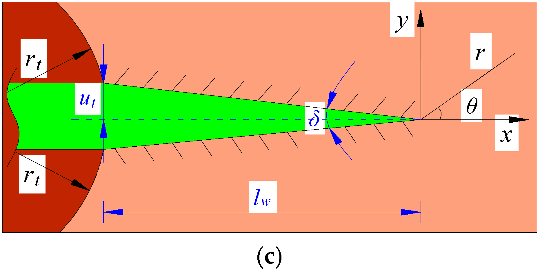
After radial fractures arise in the surrounding rock, the confined water will be driven by the high-temperature and high-pressure products of detonation to wedge into the fractures rapidly. In this process, the water will apply a uniform load to the fracture surfaces, thus accelerating fracture propagation. As fractures continue propagating in the surrounding rock, the space between fracture surfaces constantly expands and the transmission medium in fractures is gradually depressurized. As a result, the rate of fracture propagation continuously declines until the propagation process stops. Since the confined water transmits load uniformly to the fracture surfaces, fractures tend to propagate symmetrically around a hole loaded with a cylindrical explosive charge. A fracture propagation model was created to analyze the behavior of one fracture which confined water wedged into (Figure 7).
The pressure of the fracture water declines with increasing fracture lengths until fracture propagation ends. The pressure at the end of propagation can be written as follows [13,28]:
where pw is the pressure of fracture water at the end of propagation; KIc is the fracture toughness of the rock; and lw is fracture length.
The angle between the two fracture surfaces at the fracture tip is set at zero here, given that it is very small. Then thefracturelength in surrounding rock can be written in the following form [28]:
where ut is the opening displacement of the fracture; G is the shear modulus of the rock; η is a constant, defined as η = 3 − 4μ; and μ is the Poisson’s ratio.
Since the products of detonation tend to expand at constant entropy, the power-law expansion of the confined water in blast holes can be described by the equation below [13]:
where pc is the pressure of the confined water within the fractured zone in the surrounding rock; n is the number of fractures surrounding the blast hole; k is the adiabatic index; rc is the blast-hole diameter; and Dt is the thickness of the fractured zone [13,27,29].
Simultaneously solving Equations (10)–(12) gives the formula for fracture length:
Taking for example a sandstone with tensile strength of 24 MPa, Poisson’s ratio of 0.25 and elastic modulus of 41 GPa. The characteristic of fracture propagation in this sandstone for a blast-hole diameter of 45 mm was calculated. The results are presented in Figure 8.
As Figure 8 shows, the confined water needs to have a higher pressure at the beginning of expansion in order to create a larger number of fractures in the surrounding rock. For a given number of fractures, the fracture length at the end of propagation increases as the confined water pressure; a larger number of fractures is associated with a slower rate of increase. This finding is consistent with the law of conservation of energy: when the number of fractures is small, each individual fracture can possess greater kinetic energy and propagate at a faster rate in the rock.
As the number of fractures increases, each individual fracture will receive less kinetic energy and propagate at a slower rate. Therefore, if there is a technical measure that can promote fracture propagation in a desired direction while inhibiting propagation in other directions, the confined water will have a greater effect on the fracture surfaces and thus the fractures will be able to propagate farther. This will make it possible to achieve effective and directional fracturing by confined blasting in water-filled deep holes with relatively small numbers of holes and thus reduce the amount of drilling work and the cost of the technique.
The analysis concludes that confined blasting in water-filled deep holes causes damage to rock by a combination ofimpact of blast waves and the subsequent compression by the expanding water. First, the shock waves generated by detonation propagate through the confined water in holes and then instantaneously hit the hole walls, creating large numbers of compressive fractures in near-wall regions in the surrounding rock. After that, the shock waves decay into stress waves, and tensile fractures are formed and act as links between the compressive fractures. The fractures induced by wave load occur in a larger region. Later, the confined water in holes wedges into the fractures induced by wave load, under the compressive force exerted by the expanding gaseous products of detonation. Through the load path coupling between the fracture water and the water in blast hole, the dynamic and static loads can work together to overcome the drag associated with the viscosity and capillary action of fracture water and accelerate fracture formation and propagation in the surrounding rock. As the energy released by explosion gradually attenuates, the fractured rock shrinks and releases some elastic energy stored in it, giving rise to circumferential fractures in the wall rock. The circumferential fractures then connect to the earlier-formed radial fractures to form a large fractured zone, ensuring effective presplitting of hard coal and rock. The currently used hole charging blasting for deep-hole basting has to overcome three technical difficulties. The first difficulty is deep hole drilling. As the drilling depth increases, especially when the drill hole passes through the coal seam, the drill hole will collapse as the drill rod is pulled out. Therefore, it is difficult to form a drill hole. The second difficulty lies in explosive charging. As the drilling depth increases, the amount of explosives charged in the hole increases, and the explosive charging in the deep hole encounters a greater resistance. As the elevation angle of the drill hole increases, it becomes more difficult to immobilize and deliver the explosive cartridge into the hole. It is almost impossible to charge the deep hole with explosives if the drill hole collapses. The third difficulty is that failure detonation is frequent in deep-hole blasting and it is difficult to handle the mis-fire. Because of the effect of non-filled spaces inside the drill hole, continuous detonation of explosive cartridge over a long distance is difficult. As a result, failure detonation occurs frequently. Moreover, as the drill hole is severely damaged in the blasted section, it is extremely difficult to handle the undetonated explosive cartridge.
As has been pointed out by the mechanism of deep-hole confined blasting in the coal rocks, this blasting technique can overcome the defect of hole charging blasting and achieve a good blasting effect. This technique reduces the water absorption of the coal rocks, thus ensuring continuous load transfer of intra-hole water medium and increasing the utilization rate of blasting energy. The amount of intra-hole explosives needed for the blasting of an equal volume of coal rocks decreases significantly. Therefore, there is no need for full-length explosive charging of the deep hole. The intra-hole explosives are next to the hole sealing section, and the remaining space is filled with water. This method can avoid the impact of the collapse of drill hole and reduce the difficulty of explosive charging in the deep hole. By means of the excellent load transfer capacity of the intra-hole water medium, continuous detonation of the explosives is ensured. This precludes the difficulty of handling the undetonated explosives in the drill hole. The water medium is capable of extensive propagation of detonation upon the moment of blasting. The main cracks generated by the blasting will propagate along the dominant direction laid down by the blast holes. This increases the utilization efficiency of the blasting energy. Moreover, the explosives are detonated in water, which causes less environmental pollution. Apparently, deep-hole confined blasting is a superior technique for presplitting of downhole coal rocks and facilitates the drilling and blasting operation under deep hole explosive charging.
4. Practical Application of the Blasting Technique
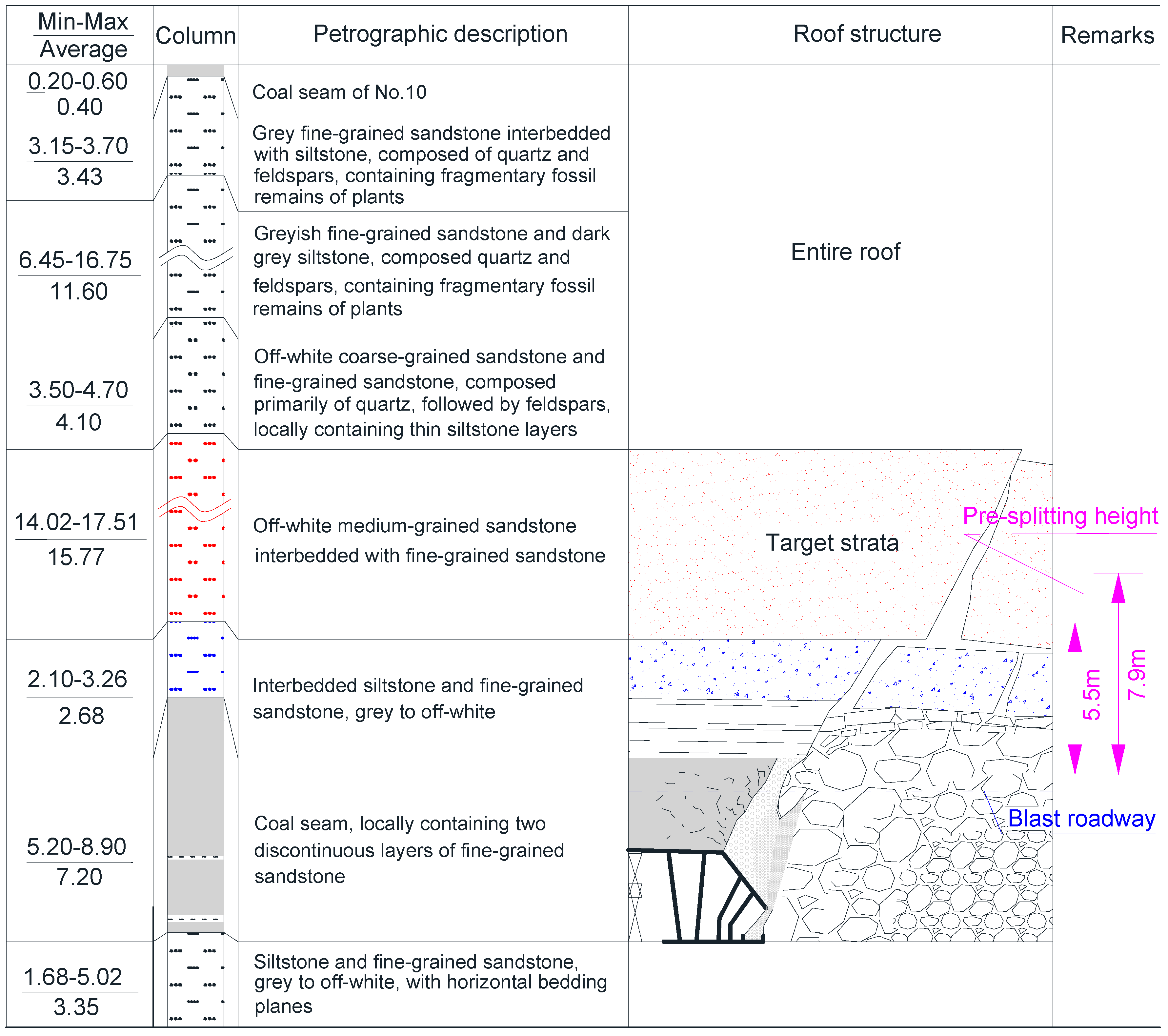
The technique proposed has been implemented to presplit the hard coal and rock at a coal mine in the Datong Coal Mine area. The elevation of the mine’s surface varies between 1304 and 1331 m. The coal seam being mined there ranges from 956 to 998 m in elevation, measures 1228 m along its strike line, and dips at between 1° and 9° with an average of 3°. Its thickness varies from 5.2 to 8.9 m, averaging 7.2 m. The cutting depth of the shearer used is 3.0 m. The coal face in this seam is 94.5 m long. This seam has a simple structure and the coal is relatively hard with a hardness coefficient of 4.8. The immediate roof is composed of interbedded siltstone and fine-grained sandstone, with its thickness varying between 2.1 and 3.3 m. The main roof, 14.0 to 17.5 m thick, consists of interbedded medium-grained sandstone and fine-grained sandstone, which are stable and hard with hardness coefficient of around 16.8. Figure 9 shows the conditions of this coal face.
4.1. Implementation of Blasting and Parameter Determination
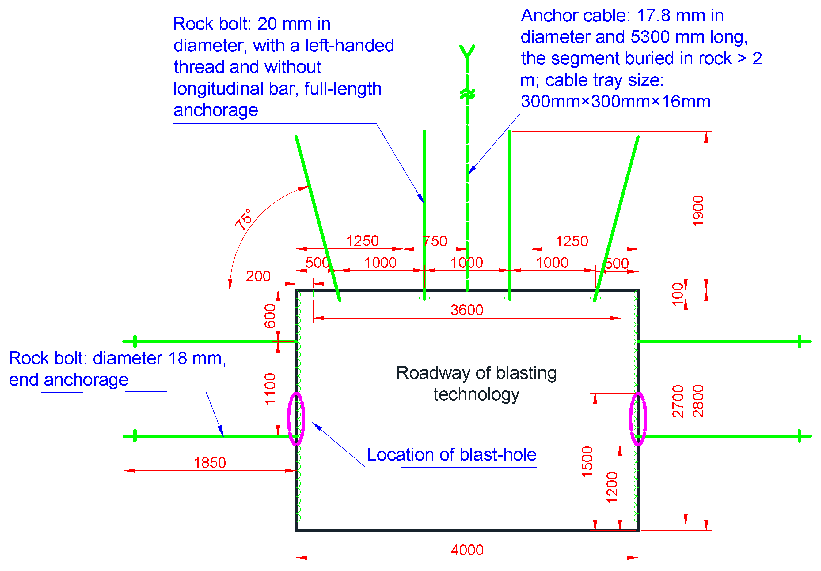
Previous research has shown that movement and failure of thick, hard main roof have a relatively great influence on the intensity of strata behavior [2,3]. In order to prevent sharp increase in rock pressure due to abrupt fracture and fall of the main roof’s long span, a roadway was made in the top coal at the middle of the face for implementation of blasting (Figure 10). Then stepwise deep-hole blasting and top-coal caving were carried out in this mine. The desired results were to reduce the length of hanging roof above the supports and mitigate the effect of the main roof’s behavior on rock pressure.
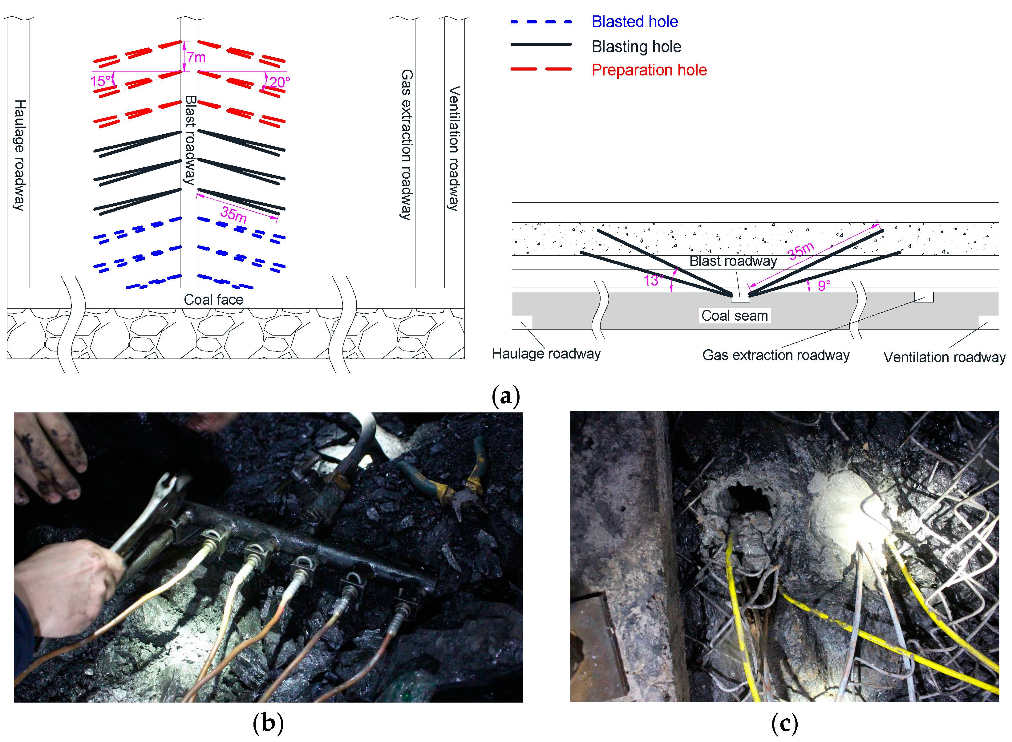
Based on local mining conditions, a plan for implementing the blasting technique proposed to precondition the hard coal and rock at this coal face was formulated. First, blast holes were drilled into the wall of the blast roadway using a set of ZLJ-650 drilling machine. The drill bit is an alloy compact bit with a 60 mm diameter and the diameter of the finished hole is 63 mm. Compass, tilt gauge and tape were used to precisely locate the holes. Three groups of blast holes were drilled, with the hole mouths located 1.2 to 1.5 m above the roadway floor on average. The holes were drilled at a location 60 m in front of the coal face each time and the blasting was always performed when the blast holes were 40 m ahead of the face. The design of the blasting site and the arrangement of pipes for water injection are presented in Figure 11.
- (1)
- This technique uses confined water as a transmission medium for detonation waves. The purpose is to prevent water leakage, force air out of pores and fractures in the surrounding rock, and take advantage of water’s ability to transfer energy efficiently. Driven by the great explosive energy, the water can penetrate into the surrounding rock like a wedge and create fractures. Before detonation, the water in the holes should be pressurized using an appropriate measure in order to enhance the results of blasting. Based on the characteristics of the pipe network in the blast roadway, the design pressure of the confined water was determined to be 2.0 MPa.
- (2)
- Research showed that the tensile fracture zone created by blasting in a water-filled hole had a radius 10–15 times that of the blast-hole diameter [13,15]. When the blast-hole diameter was 60 mm, the tensile fracture zone in the surrounding rock had a radius of 0.33–0.49 m. The fractures surrounding pilot holes were about 0.13 m long. After the expanding confined water wedged into fractures in the surrounding rock, the water-bearing fractures would propagate at least 5.0 m [13]. These suggest that the minimum spacing between blast holes and pilot holes in hard roof should be about 5.5 m. Given the high efficiency of energy use during confined blasting in water-filled deep holes, the spacing between blast holes was increased to 7.0 m in practical application for the purpose of avoiding mutual interference between strong dynamic loads from adjacent holes.
- (3)
- Determining the amount of explosive needed is an important task in designing a blasting plan, as the amount of explosive used has a direct bearing on the results and cost of blasting. The most common method is to calculate the mass of explosive according to volume. Considering that the sandstones in the roof are quite hard, the explosive consumption coefficient per unit volume was set at 1.2 for Class 3 emulsion explosives permitted for use in coal mines. Then the mass of explosive required to create an effective damage zone around a single hole was estimated to be 106.7 kg. Given the high efficiency of explosive energy use in the presence of water, it is reasonable to multiply this amount by a proper reduction factor to calculate the amount of explosive for the technique proposed. In this case, a reduction factor of 0.3 [13] was adopted and the amount of explosive for a single hole was estimated to be 32 kg.
4.2. Main Blasting Operations
The drilling was undertaken in the blast roadway at a location 60 m in front of the coal face each time, in order to minimize the influence of mining and coal caving on the results of blasting. Then boreholes with a diameter of 60 mm were drilled into the roadway wall using a drill rig for geologic exploration. After the drilling was completed, the holes were loaded with explosive, sealed, and then water was injected into the holes until its pressure reached the preset level. Then different parts of the detonation network were connected, followed by detonation. The main operations involved in this blasting technique are demonstrated in Figure 12.
- (1)
- The explosive material adopted in this study was a Class 3 emulsion explosive permitted for use in coal mines. The explosive charges were connected by a type of detonating cords for use in mines and detonated by an instantaneous electrical detonator, which was initiated using a trigger. Before loading, a tamping bar was used to clean coal and rock powder off the holes. Then the actual depths of the holes were measured and recorded. Then explosive charges were put into the blast holes properly with the help of a fixture, and the detonating cords were taken out of the holes along the hole wall in sequence.
- (2)
- A sealing device fixed with an injection pipe and an outlet pipe was used to seal the holes. The seal length was 1/3 of the depth of each hole. The outlet pipe extended to the bottom of each hole and had a strainer at this end to prevent blockage. The injection pipes were longer than the sealing device.
- (3)
- After that, the detonating cords from different holes were connected and the pipe network for delivering confined water was established. Then the valves on the injection pipes were opened and the valves on the outlet pipes were opened slightly so that the injected water could drive the air out of the holes. Each injection pipe was provided with a check valve to prevent back-flow of the confined water. Figure 13 shows the profile of a water-filled blast hole.
- ◆
- During water injection, the valve on each outlet pipe was open until the pressure gauge installed on the outlet pipe indicated a steady increase in pressure. As the water pressure in the holes reached 2 MPa, the valve on the injection pipes were closed. The seals on the holes were rechecked to ensure that the confined water in the holes could not get out. Once a pressure decline was observed in a hole, the valve on the corresponding injection pipe was opened slightly for pressurization.
- ◆
- Initiation was done outside the air door of the blast roadway and all personnel must leave the blast roadway before initiation.
4.3. Effectiveness of Blasting in Roof Control
Stepwise blasting and top-coal caving were undertaken during the cyclic advance of the coal face. The blast parameters used in the conventional blasting and confined blasting experiments are provided in Table 1.
Using liquid water as the detonation transmission medium can improve the efficiency of explosive energy higher. This means that the number of explosives required is reduced, facilitating the loading of explosives to a deep borehole. As Table 1 shows, for given hole parameters, the amount of explosive needed in confined blasting was only 70% of that needed in conventional blasting. In confined blasting, each blast hole had a 7 m long section filled with confined water. Figure 14 reveals the degrees of damage to the coal rib under the two blasting conditions. As can be seen in Figure 14, the coal rib was damaged to a limited degree under conventional blasting: equivalent length of the fracture face was about 0.7 m, the depth of the fractured zone was only around 0.3 m, and the blast craters left on the surface of the rock mass blasted had relatively small volumes. In comparison, the confined blasting caused serious damage to the coal rib due to its much higher efficiency of explosive energy. The resulting fracture face had an equivalent length of about 7.0 m and the fractured zone was about 6.5 m deep.
Additionally, seven rock bolts were drawn out and the blast craters were large in size. The coal thrown off the rib occupied nearly 1/3 of the blast roadway, as measured in the cross section. These results provide solid evidence that the technique of confined blasting in water-filled deep holes is effective in presplitting hard coal and rock.
The support resistance at the coal face was monitored. Table 2 shows the distribution of support resistance under confined blasting.
The measured average support resistance was 6495.4 kN, about 86.6% of the working resistance. During weighting, the mean value peaked at 7111.6 kN, which is equivalent to 94.8% of the working resistance. This suggests that the roof’s margin of safety during mining was adequate to ensure safe production.
The average time-weighted resistance on the supports was 6749.9 kN, about 86.6% of the working resistance. The mean value peaked at 7069.8 kN, or 94.3% of the working resistance. It is clear that the implementation of the confined blasting technique proposed has effectively reduced the rock pressure at the face.
5. Conclusions
- (1)
- Mining in thick and extra-thick coal seams can cause large-scale disturbance to overburden. The roof strata in the disturbed region show structural evolution in succession during mining and ultimately form a complex structure. Destabilization of the upper stratais the main factor driving strong strata behavior.
- (2)
- The intensity of the shock wave caused by the detonation wave in the medium increases in an approximately linear manner with the increase in the initial density of the medium. By properly increasing the pressure of the detonation-transferring medium in the drill hole, a full solid-liquid coupling can be achieved. This will enhance the rock-breaking capacity of the detonation wave on the surrounding rocks.
- (3)
- The confined water in the drill hole is wedged into the wave-induced cracks under the expansion and squeezing of the detonation products. The dynamic and static loads of water medium work in combination along the dynamic pressure transfer pathway, which facilitates crack propagation in the surrounding rocks.
- (4)
- The mechanical model describing the process of water medium wedging into the cracks and promoting crack growth in the surrounding rocks during detonation. Under a fixed number of cracks, the ultimate length of the cracks increases with the expansion pressure of the water medium. The greater the number of the cracks, the lower the variation rate of the initial expansion pressure of the water medium is.
- (5)
- The incompressibility of water is utilized. The dynamic pressure transfer capacity of the confined water is combined with the expansion and squeezing of the water after blasting to promote crack propagation. This is the root cause of high efficiency presplit blasting using the technique in coal rocks.
- (6)
- A plan for implementing confined blasting to presplit hard coal and rock was designed during thick seam mining in the Datong Coal Mine area, and a comparative analysis suggests that theconfined blasting technique caused in significant damage to the coal and rock with less explosive consumption and a substantial reduction in rock pressure.
Acknowledgments
Financial support for this work, provided by the Fundamental Research Funds for the Central Universities (2017QNA23).
Author Contributions
Jingxuan Yang and Changyou Liu conceived and designed the technical scheme; Bin Yu provided the site practice and some previous research results; Jingxuan Yang wrote the paper.
Conflicts of Interest
The authors declare no conflict of interest.
References
- Yu, B. Study on Strong Pressure Behavior Mechanism and Roof Control of Fully Mechanized Top Coal Caving in Extra Thickness Seam in Datong Coal Mine. Ph.D. Thesis, China University of Mining and Technology, Xuzhou, China, 2014. [Google Scholar]
- Yang, J.X.; Liu, C.Y.; Yu, B.; Liu, J.R. Impact effect caused by the fracture of thick and hard roof structures in a longwall face. J. China Univ. Min. Technol. 2014, 43, 8–15. [Google Scholar]
- Yu, B.; Zhao, J.; Kuang, T.J.; Meng, X.B. In situ investigations into overburden failures of a super-thick coal seam for longwall top coal caving. Int. J. Rock Mech. Min. Sci. 2015, 78, 155–162. [Google Scholar] [CrossRef]
- Yang, J.X.; Liu, C.Y.; Yu, B.; Wu, F.F. The effect of a multi-gob pier-type roof structure on coal pillar load-bearing capacity and stress distribution. Bull. Eng. Geol. Environ. 2015, 74, 1267–1273. [Google Scholar] [CrossRef]
- Verma, H.K.; Samadhiya, N.K.; Singh, M.; Goel, R.K.; Singh, P.K. Blast induced rock mass damage around tunnels. Tunn. Undergr. Space Technol. 2018, 71, 149–158. [Google Scholar] [CrossRef]
- Marko, B.; Celso, R.; Deane, R. Finite element analysis of blast-induced fracture propagation in hard rocks. Comput. Struct. 2017, 182, 1–13. [Google Scholar]
- Singh, P.K.; Roy, M.P.; Paswan, R.K.; Sarim, M.D.; Kumar, S.; Jha, R.R. Rock fragmentation control in opencast blasting. J. Rock Mech. Geotech. Eng. 2016, 8, 225–237. [Google Scholar] [CrossRef]
- Piyush, R.; Hakan, S.; Per-Arne, L.; Uday, K. Measurement-while-drilling technique and its scope in design and prediction of rock blasting. Int. J. Min. Sci. Technol. 2016, 26, 711–719. [Google Scholar]
- Wang, Y.B. Study of the dynamic fracture effect using slotted cartridge decoupling charge blasting. Int. J. Rock Mech. Min. Sci. 2017, 96, 34–46. [Google Scholar] [CrossRef]
- Ramezanzadeh, A.; Hood, M. A state-of-the-art review of mechanical rock excavation technologies. Int. J. Min. Environ. Issues 2010, 1, 29–39. [Google Scholar]
- Wu, W.Y.; Li, J.X. Experimental study and application on control blasting with water coupled charge in tunneling. Nonferrous Met. 2003, 5, 20–21. [Google Scholar]
- Ming, F.; Zhu, W.H.; Li, Q.D. Application of water-couple charge blasting in tunnel excavation. Chin. J. Undergr. Space Eng. 2012, 8, 1008–1013. [Google Scholar]
- Yang, J.X. Study on Confined Blasting Control Mechanism of Hard Coal Rock with High Safety and Efficiency and Test Analysis. Ph.D. Thesis, China University of Mining and Technology, Xuzhou, China, 2015. [Google Scholar]
- Wang, W.; Li, X.C.; Shi, L.; Fang, Z.M. Discussion on decoupled charge loosening blasting in deep rock mass. Rock Soild Mech. 2008, 29, 2837–2842. [Google Scholar]
- Zong, Q.; Luo, Q. Experimental study on distribution character of blasting stress when boreholes with water couple charge. J. Exp. Mech. 2006, 21, 393–398. [Google Scholar]
- Yan, S.L.; Xu, Y. Numerical simulation of water-coupled charge rock blasting mechanism. Chin. J. Undergr. Space Eng. 2005, 1, 921–924. [Google Scholar]
- Anderson, C.E.; Behner, T.; Weiss, C.E. Mine blast loading experiments. Int. J. Impact Eng. 2011, 38, 697–706. [Google Scholar] [CrossRef]
- Jin, Z.Y.; Yin, C.Y.; Chen, Y.; Hua, H.X. One-dimensional analytical model for the response of elastic coatings to water blast. J. Fluids Struct. 2015, 59, 37–56. [Google Scholar] [CrossRef]
- Boteler, J.M.; Sutherland, G.T. Tensile failure of water due to shock wave interactions. J. Appl. Phys. 2004, 96, 6919–6924. [Google Scholar] [CrossRef]
- Deshpande, V.S.; Fleck, N.A. One-dimensional response of sandwich plates to under water shock loading. J. Mech. Phys. Solids 2005, 53, 2347–2383. [Google Scholar] [CrossRef]
- Pereira, J.M.; Campos, J.; Lourenco, P.B. Masonry infill walls under blast loading using confined underwater blast wave generators. Eng. Struct. 2015, 92, 69–83. [Google Scholar] [CrossRef] [Green Version]
- Cho, S.H.; Nakamura, Y.; Kaneko, K. Dynamic fracture process analysis of rock subjected to stress wave and gas pressurization. Int. J. Rock Mech. Min. Sci. 2004, 41, 433–440. [Google Scholar] [CrossRef]
- Goodarzi, M.; Mohammadi, S.; Jafari, A. Numerical analysis of rock fracturingby gas pressure using the extended finite element method. Pet. Sci. 2015, 12, 304–315. [Google Scholar] [CrossRef]
- Donze, F.V.; Bouchez, J.; Magnier, S.A. Molding fractures in rockblasting. Int. J. Rock Mech. Min. Sci. 1997, 34, 1153–1163. [Google Scholar]
- Edri, I.; Savir, Z.; Feldgun, V.R.; Karinski, Y.S.; Yankelevsky, D.Z. On blast pressure analysis due to a partially confined explosion: I. Experimental studies. Int. J. Prot. Struct. 2011, 2, 1–20. [Google Scholar] [CrossRef]
- Li, X.B. Rock Drilling and Blasting Engineering; Central South University Press: Changsha, China, 2011. [Google Scholar]
- Dai, J. Dynamic Behaviours and Blasting Theory of Rock; Metallurgical Industry Press: Beijing, China, 2013. [Google Scholar]
- Fan, T.Y. Principle and Application of Fracture Mechanics; Press of Beijing Institute of Technology: Beijing, China, 2006. [Google Scholar]
- Liu, C.Y.; Yang, J.X.; Yu, B. Rock-breaking mechanism and experimental analysis of confined blasting of borehole surrounding rock. Int. J. Min. Sci. Technol. 2017, 27, 795–801. [Google Scholar]
Figure 1.
Plane layout of Jurassic and Carboniferous coal seams.

Figure 2.
Roof structure during mining in an extra-thick coal seam.

Figure 3.
Strong strata behavior: (a) Crushed face supports; (b) Broken roadway pillars.

Figure 4.
Roof weighting at alternate long and short intervals.
Figure 5.
Transmission and reflection of detonation waves at an interface between two media.

Figure 6.
Effect of surrounding medium’s density on the pressure upon the medium behind the shock wavefront.
Figure 6.
Effect of surrounding medium’s density on the pressure upon the medium behind the shock wavefront.

Figure 7.
Model of fracture propagation after confined blasting in a water-filled deep hole: (a) Effects of deep-hole rock blasting; (b) Propagation of fractures in surrounding rock; (c) Propagation of a single fracture.
Figure 7.
Model of fracture propagation after confined blasting in a water-filled deep hole: (a) Effects of deep-hole rock blasting; (b) Propagation of fractures in surrounding rock; (c) Propagation of a single fracture.


Figure 8.
Effect of expansion of confined water on fracture propagation.
Figure 9.
Stratigraphic column of the coal face.

Figure 10.
Design of the blast roadway.

Figure 11.
Design of the blasting site and arrangement of pipes: (a) Plan and section of the blasting site; (b) Arrangement of injection pipes; (c) Fixing a pipe at each hole mouth.
Figure 11.
Design of the blasting site and arrangement of pipes: (a) Plan and section of the blasting site; (b) Arrangement of injection pipes; (c) Fixing a pipe at each hole mouth.

Figure 12.
Main operations involved in confined blasting in water-filled deep holes.

Figure 13.
Schematic of water injection for the blast holes: (a) Profile of a water-filled blast hole; (b) Synchronous water injection into multiple holes; (c) Discharge from the outlet pipes.
Figure 13.
Schematic of water injection for the blast holes: (a) Profile of a water-filled blast hole; (b) Synchronous water injection into multiple holes; (c) Discharge from the outlet pipes.

Figure 14.
Degrees of damage to the coal rib under the two blasting conditions: (a) Apparent effect of conventional rock blasting; (b) Apparent effect of confined blasting in water-filled deep holes.
Figure 14.
Degrees of damage to the coal rib under the two blasting conditions: (a) Apparent effect of conventional rock blasting; (b) Apparent effect of confined blasting in water-filled deep holes.


Table 1.
Blast parameters for the two blasting conditions.
| Angle of Horizontal Rotation (°) | Elevation Angle (°) | Vertical Height (m) | Hole Depth (m) | Seal Length (m) | Length of Charge (m) | Charge Weight (kg) | ||
|---|---|---|---|---|---|---|---|---|
| Conventional Blasting | Confined Blasting | Conventional Blasting | Confined Blasting | |||||
| 20 | 13 | 7.87 | 35 | 12 | 23 | 16 | 46 | 32 |
| 15 | 13 | 7.87 | 35 | 12 | 23 | 16 | 46 | 32 |
| 15 | 9 | 5.48 | 35 | 12 | 23 | 16 | 46 | 32 |
Table 2.
Distribution of support resistance under confined blasting.
| Support Resistance Category | Location of Measuring Line | Support Resistance (kN) | ||
|---|---|---|---|---|
| Average | Mean Square Error | Maximum | ||
| Support resistance | Head | 5930.7 | 1024.4 | 6791.5 |
| Middle | 7012.1 | 1125.2 | 7386.6 | |
| Tail | 6543.3 | 1432.5 | 7156.7 | |
| Mean | 6495.4 | 1194.0 | 7111.6 | |
| Time-weighted resistance | Head | 6456.3 | 1391.4 | 6978.3 |
| Middle | 6958.4 | 1082.0 | 7220.0 | |
| Tail | 6835.1 | 1380.4 | 7011.0 | |
| Mean | 6749.9 | 1284.6 | 7069.8 | |
© 2017 by the authors. Licensee MDPI, Basel, Switzerland. This article is an open access article distributed under the terms and conditions of the Creative Commons Attribution (CC BY) license (http://creativecommons.org/licenses/by/4.0/).
Share and Cite
MDPI and ACS Style
Yang, J.; Liu, C.; Yu, B. Application of Confined Blasting in Water-Filled Deep Holes to Control Strong Rock Pressure in Hard Rock Mines. Energies 2017, 10, 1874. https://doi.org/10.3390/en10111874
AMA Style
Yang J, Liu C, Yu B. Application of Confined Blasting in Water-Filled Deep Holes to Control Strong Rock Pressure in Hard Rock Mines. Energies. 2017; 10(11):1874. https://doi.org/10.3390/en10111874
Chicago/Turabian StyleYang, Jingxuan, Changyou Liu, and Bin Yu. 2017. "Application of Confined Blasting in Water-Filled Deep Holes to Control Strong Rock Pressure in Hard Rock Mines" Energies 10, no. 11: 1874. https://doi.org/10.3390/en10111874
Note that from the first issue of 2016, this journal uses article numbers instead of page numbers. See further details here.