Economic Analysis of Flat-Plate and U-Tube Solar Collectors Using an Al2O3 Nanofluid

1
Graduate School of Chosun University, Chosun University, 303 Pilmun-daero, Dong-gu, Gwangju 61452, Korea
2
Department of Mechanical Engineering, Chosun University, 303 Pilmun-daero, Dong-gu, Gwangju 61452, Korea
*
Author to whom correspondence should be addressed.
Energies 2017, 10(11), 1911; https://doi.org/10.3390/en10111911
Submission received: 19 October 2017
/
Revised: 9 November 2017
/
Accepted: 15 November 2017
/
Published: 20 November 2017
(This article belongs to the Section D: Energy Storage and Application)
Abstract
:In this study, the efficiencies of flat-plate and U-tube solar collectors were investigated experimentally when an Al2O3 nanofluid was used as a working fluid and compared to those of solar collectors using water. The energy savings and CO2 and SO2 generated were calculated and compared to those of solar collectors using water. In addition, based on the experimental results, an economic analysis of the use of solar collectors in various countries was performed. As the concentration of the Al2O3 nanofluid increased, the performance of the solar collector improved. The highest efficiency for the solar collectors was shown at the concentration of 1.0 vol % with the nanoparticle size of 20 nm. The maximum efficiencies of the flat-plate and U-tube solar collectors using a 1.0 vol %-Al2O3 nanofluid with 20-nm nanoparticles was 74.9% and 72.4%, respectively, when the heat loss parameter was zero. The efficiencies of the flat-plate and U-tube solar collectors using Al2O3 nanofluid were 14.8% and 10.7% higher, respectively, than those using water. When 50 EA (each) flat-plate solar collectors were operated for one year using an Al2O3 nanofluid, the coal use, generated CO2, and generated SO2 were 189.99 kg, 556.69 kg, and 2.03 kg less than those of solar collectors using water, respectively. In addition, the largest electricity cost reduction was in Germany.
1. Introduction
Because of the population growth and industrial development in the world, the use of energy and fossil fuel has increased. The continuous use of fossil fuels produces environmental pollutants, such as CO2 and SO2, and these pollutants affect climate change and cause various environmental problems, such as accelerated global warming. Many countries signed the Paris Climate Change Accord on 12 December 2015 to reduce greenhouse gas emissions, reduce the annual average temperature increase of the earth, and to maintain a low temperature increase. Therefore, numerous studies on the development and application of various renewable energies have been performed. Solar energy is a renewable energy with unlimited energy, unlike fossil fuels, and has various advantages; for example, it is not concentrated in a specific area, and does not cause environmental pollution.
The most common way to use solar energy is to use a solar collector. A solar collector can be classified as a flat-plate solar collector, an evacuated-tube solar collector, or a parabolic solar collector. In addition, the solar collector also can be divided into low-temperature, medium-temperature, and high-temperature applications depending on the operating temperature. The flat-plate and evacuated-tube solar collectors are widely used. The flat-plate solar collector is a common solar collector for residential hot water and space heating, and it has advantages such as a low assembly cost, easy installation, and inexpensive management [1,2]. The flat-plate solar collector is made of a glass or plastic cover and a dark-colored absorption plate. The evacuated-tube solar collector can reduce heat loss by convection and conduction owing to the use of vacuum technology. Thus, it can be used in the middle-temperature and the high-temperature applications even though it has been used in the cold environmental condition. In addition, it has advantages such as a light weight and easy installation because it involves a 30% reduction in the installation area.
However, the energy efficiency of a solar collector is not economical because of the high installation cost. Thus, a lot of studies have been performed to increase the energy density and efficiency of the solar collector. The application of various nanofluids in the solar collector system as a working fluid is a developed method to improve the system efficiency. A nanofluid is a solid-liquid mixture with solid particles in a basic fluid, and the solid particles are 1 nm to 100 nm in size [3,4]. Nanofluids are used to increase the heat transfer, and this effect can be obtained by dispersing non-metallic or metallic particles with a nano-size in the basic fluid. Therefore, several previous studies on the measurement of thermal conductivity and the dispersion stability of various nanofluids have been performed [5]. Charab et al. [6] predicted a degree of thermal conductivity enhancement through an experiment on the properties of Al2O3 + TiO2/water nanofluids, and showed improved thermal performance in the nanofluids. Lee et al. [7] conducted an experiment on the heat transfer rate and absorption rate in a carbon nanotube (CNT) and Al2O3 nanofluid, and showed a 17% and 16% improved heat transfer rate and absorption rate at 0.02 vol %-CNT compared to that of the basic fluid, respectively.
Numerous studies measuring the thermal performance in a solar collector with various nanofluids have been conducted. Verma et al. [8] used six nanofluids: SiO2/water, TiO2/water, Al2O3/water, CuO/water, graphene/water, and multi-walled carbon nanotubes (MWCNT)/water, in a flat-plate solar collector. The experimental results showed that the energy efficiency of MWCNT/water was 29.3% higher than that of water. Moghadam et al. [9] measured the performance of a flat-plate solar collector by applying a CuO nanofluid. In a flat-plate solar collector, the 0.4 vol %-CuO nanofluid with 30-nm nanoparticles showed a 16.7% higher efficiency than that of water. Noghrehabadi et al. [10] showed that the efficiency of a flat-plate solar collector by using an SiO2 nanofluid was higher than that of water, and the efficiency also increased as the mass flow rate increased. However, the efficiency increase was not significant. In addition, Yousefi et al. [11] investigated the effect of the mass flow rate of the working fluid, the concentration of the nanofluid, and the surfactant on the efficiency of a solar collector and reported that the efficiency of the solar collector using a 0.2 vol %-Al2O3 nanofluid was 28.3% higher than that using water. Besides that, the efficiency of the solar collector increased up to 15.63% when a surfactant was used. Marquez and Prieto [12] investigated the variation of the efficiency when the tilt angle of a flat-plate solar collector was varied, and reported that the average change in the efficiency for the tilt angle was 21.6%. Ge et al. [13] investigated the exergy efficiency in a flat-plate solar collector. When the ambient temperature was 20 °C, the solar radiation was 800 W/m2, the mass flow rate of the working fluid was 0.05 kg/s, the inlet temperature of the working fluid was 50 °C, the useful exergy rate was 5.96%, and the loss exergy rate was the largest at 72.9%. Overall, in case of using nanofluid as the working fluid in a flat-plate solar collector, the efficiency of the solar collector could be improved [14,15,16,17,18].
Studies on the application of a nanofluid in an evacuated-tube solar collector have also been performed. Ghaderian and Sidik [19] improved the thermal properties by using an Al2O3 nanofluid in an evacuated-tube solar collector, and the efficiency of the evacuated-tube solar collector using a 0.06 vol %-Al2O3 nanofluid was 58.65% higher than that of water. Sabiha et al. [20] measured the performance of an evacuated-tube solar collector, and a 93.4% improved efficiency was shown when a 0.2 vol %-single-walled carbon nanotube (SWCNT) nanofluid was used, which was 71.8% higher than that using water. Iranmanesh et al. [21] investigated the thermal efficiency when a graphene nanofluid was used in an evacuated-tube solar collector. The maximum efficiency with a 0.1 wt %-graphene nanofluid was 90.7%, which was 35.8% higher than that with water.
Research on the application of various nanofluids in a direct absorption solar collector has also been performed. Delfani et al. [22] studied the effect of the internal emissivity, the mass flow rate of the nanofluid, and the concentration of the MWCNT nanoparticles on the efficiency when an MWCNT nanofluid was used in a direct absorption solar collector. The thermal performance of the solar collector increased with the increase of the concentration and mass flow rate of the nanofluid. In addition, the maximum efficiency was shown for a 100 ppm MWCNT nanofluid, and the performance improvement was 29% higher than that of water. Menbari et al. [23] reported that the application of a CuO nanofluid in a direct absorption solar collector could increase the thermal efficiency by 18–52% when the concentration of the CuO nanofluid increased by 0.006%. Karami et al. [24] experimentally showed that the performance of the direct absorption solar collector could be increased by increasing the concentration of the CuO nanofluid. The maximum efficiency was obtained when the mass flow rate of the working fluid was 90 L/h and the concentration of the CuO nanofluid was 100 ppm. This was 17% higher than that with water. In addition to the studies presented this paper, many other studies have been conducted to measure the efficiency of a direct absorption solar collector by applying a nanofluid as a working fluid [25,26,27,28].
Previous studies have shown that applying a nanofluid as a working fluid in a solar collector can produce a higher thermal efficiency than that produced when applying a basic fluid. However, experimental studies of an efficiency comparison using a nanofluid in flat-plate and U-tube solar collectors are not sufficient in the literature. Moreover, experimental studies on performance characteristics using wide operating conditions are limited. In addition, an economic analysis on the performance improvement when a nanofluid is used in the two types of solar collectors and a comparison of the electric usage and cost in representative cities have not been carried out. In this study, the thermal efficiency of a flat-plate and a U-tube solar collector based on the size of the Al2O3 nanoparticle and the concentration of the Al2O3 nanofluid was experimentally measured. The experimental results were used to calculate the reduction of coal use, generated CO2, and generated SO2, and those were compared to those of solar collectors using water for one year under maximum efficiency. In addition, based on the calculated results, the saved energy was replaced by the amount of coal usage, and that was converted into electricity and the reduction of the electricity cost in several countries. The electricity cost was also analyzed and compared when the heat pump and electric heater were used with the reduced electricity.
2. Experimental Setup and Procedure
2.1. Experimental Setup and Test Method
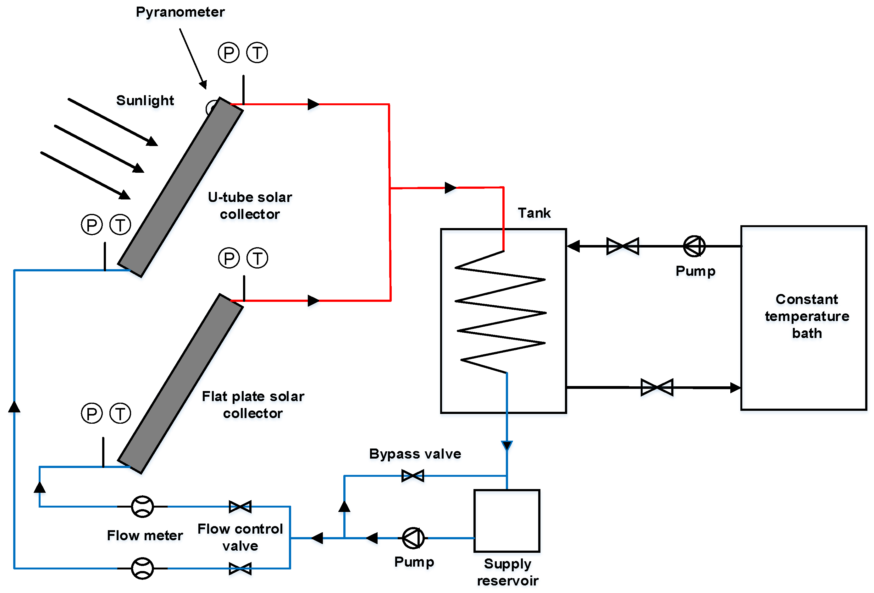
Because the performance of a solar collector is influenced by the outdoor temperature and solar radiation, the performance test of a solar collector should be performed with a wide range of operating conditions. Figure 1 shows a configuration of the experimental apparatus of this study. Under the same operating condition, to compare the efficiency of the flat-plate and U-tube solar collectors using an Al2O3 nanofluid and water, the experiment was carried out using the same location and time for four solar collectors. The test setup consisted of two types of each solar collector, a constant thermal bath for removing the heat load, a heat storage tank, and a circulation pump. Water and Al2O3 nanofluid were used as the working fluid simultaneously. To investigate the efficiency of the solar collector, the heat gain in the solar collector should be calculated. Thus, the mass flow rate of the working fluid, the temperature at the inlet and outlet of the solar collector, the solar radiation, and the ambient temperature were measured. The temperature of the working fluid at the inlet and outlet of the solar collector and the ambient temperature were measured by a T-type thermocouple. The solar radiation was measured using a solar radiation meter. Moreover, a mass flow meter was used to measure the mass flow rate of the working fluid. The data from the mass flow meter, thermocouple, and solar radiation meter were collected using a data logger.
The uncertainties of the measuring equipment of this study are listed in Table 1. The uncertainty in the experimental results was directly related to the efficiency of the solar collector. That was caused by the error of the measuring equipment from the mass flow meter, thermocouple, and solar radiation meter. The uncertainty of the efficiency in the solar collector was calculated using Equation (1) [29].
where, m is the mass flow rate of working fluid, G is the solar radiation, and the parameters To and Ti are the outlet and inlet temperature of the solar collector, respectively. Using Equation (1), the maximum uncertainty of the experimental results for the wide operating conditions was approximately 3.02%, and the average uncertainty was 1.44%.
The specifications of the flat-plate and U-tube solar collectors are listed in Table 2. The installation angle of the two types of solar collectors was 45° to the south. This was a typical installation angle in Korea for use in the winter season. The experiment was carried out from 10:00 a.m. to 5:00 p.m. in Gwangju (Latitude: 35° N, Longitude: 126° E), Korea.
The efficiency of the solar collector was measured according to the size of the Al2O3 nanoparticle and the concentration of the Al2O3 nanofluid. The sizes of the Al2O3 nanoparticles in the Al2O3 nanofluid were 20 nm, 50 nm, and 100 nm. The concentrations of the Al2O3 nanofluid were 0.5 vol %, 1.0 vol %, and 1.5 vol %. The mass flow rate of the working fluid (water and Al2O3 nanofluid) was fixed at 0.047 kg/s. The detailed experimental conditions in this study are presented in Table 3.
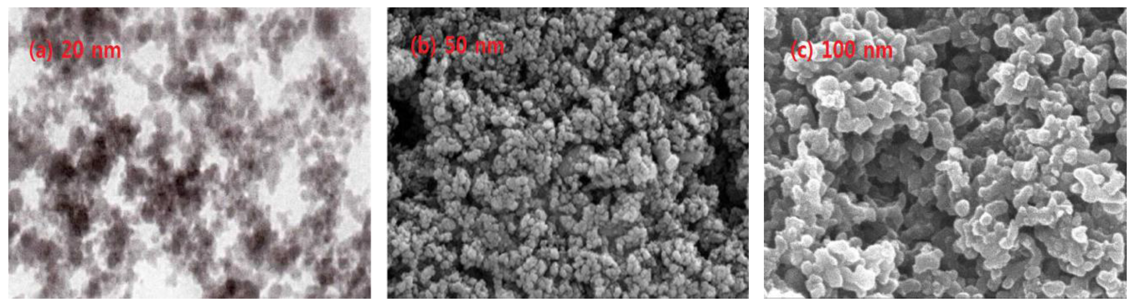
Figure 2 presents an SEM (scanning electron microscopy) image according to the size of the Al2O3 nanoparticles used in this experiment. The shape of the Al2O3 nanoparticle was spherical, and the particles were dispersed in the nanofluid. The precipitation of dispersed nanoparticles in the nanofluid after one week was not observed.
2.2. Efficiency Calculation of the Solar Collector
The specific heat of the Al2O3 nanofluid should be determined in order to calculate the efficiency of the solar collector, and it was obtained as follows.
The parameters cp(bf) and cp(n) are the specific heat of the basic fluid and Al2O3 nanoparticles, and ρbf and ρn are the density of the basic fluid and Al2O3 nanoparticles, respectively. is the concentration of the nanofluid.
By using the useful heat gain, solar radiation, and surface area of the solar collector, the efficiency of the solar collector could be calculated with Equation (3).
The parameter Qu is the useful heat of the solar collector, G is the solar radiation, and Ac is the surface area of the solar collector. The parameters ṁ and cp are the mass flow rate of the working fluid and the specific heat of the water or nanofluid, respectively. The parameters To and Ti are the outlet and inlet temperature of the solar collector, respectively.
Based on the experimental results, an economic analysis on the use of the solar collectors in various countries was performed. Using the climate data, the difference in the heat gain of solar collectors using an Al2O3 nanofluid and water for one year was calculated. The heat amounts obtained from the solar collectors using the Al2O3 nanofluid compared to that using water during one year were calculated, and the results were converted to the reduction of coal use and CO2 and SO2 generated. In addition, these were converted to the electric usage and electric cost for six representative cities in the world, and the electric cost was compared when the electric heater and heat pump were used.
3. Results and Discussion
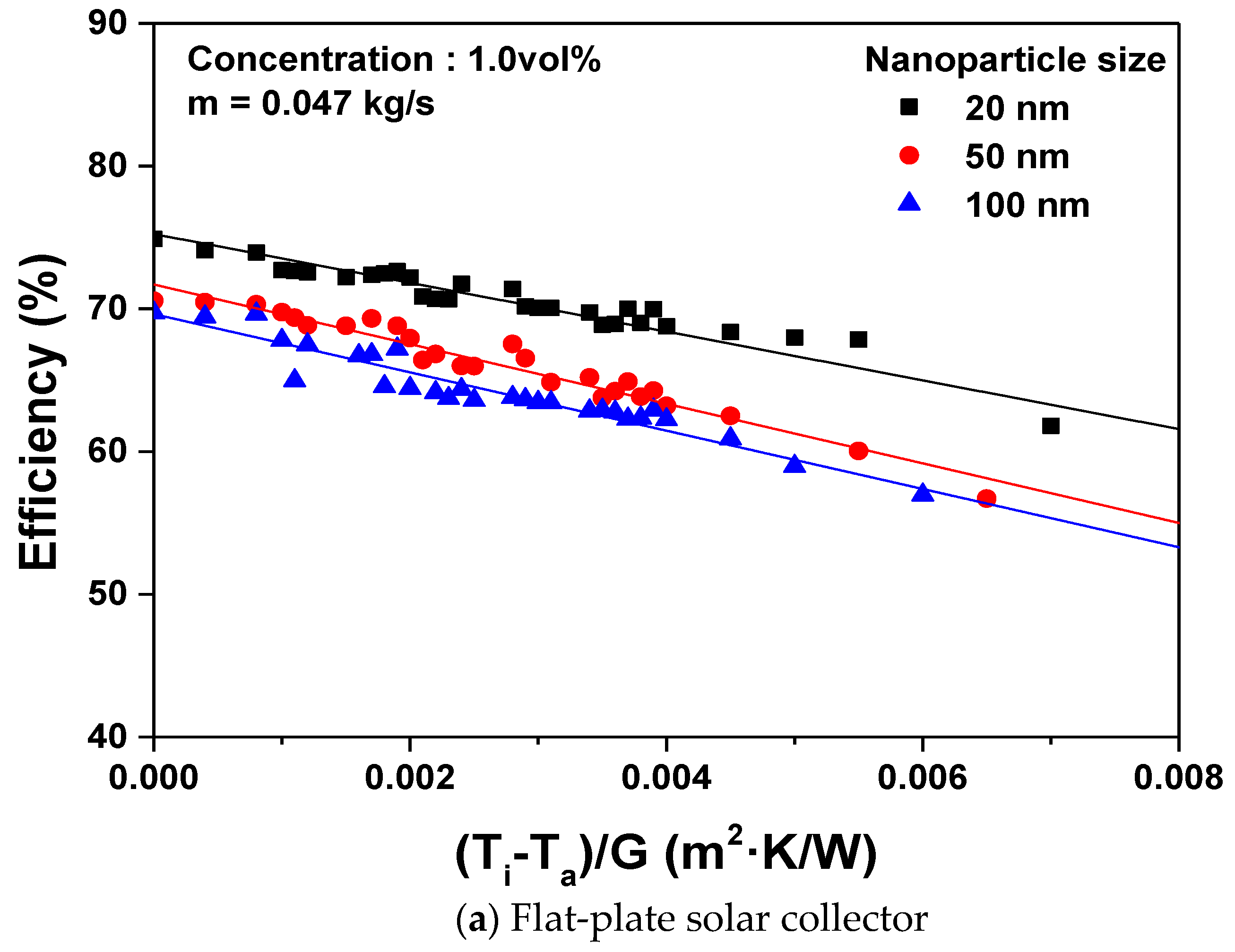
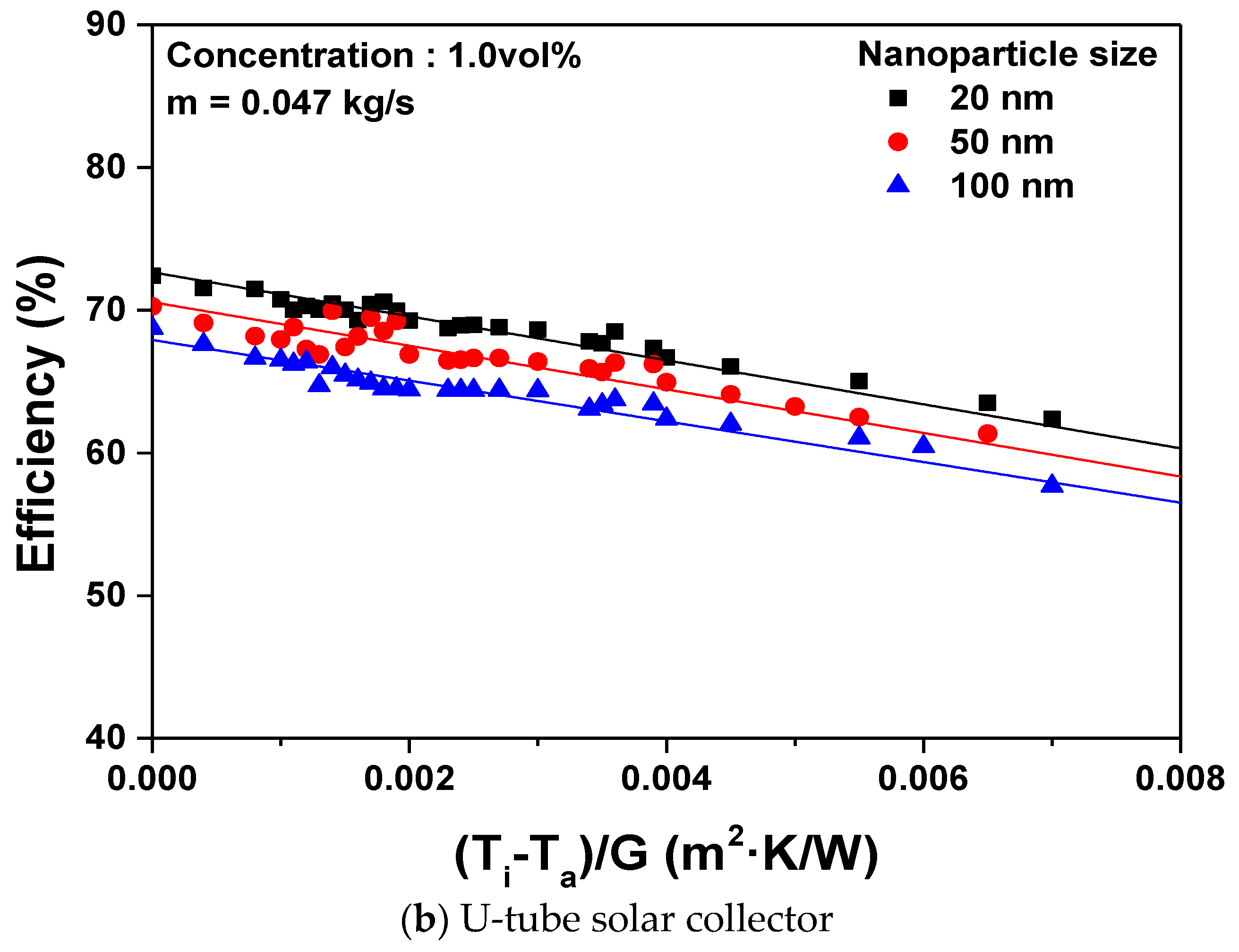
Figure 3 shows the efficiency variations in the flat-plate and U-tube solar collectors according to the nanoparticle sizes when the mass flow rate of the working fluid and the concentration of the Al2O3 nanofluid was 0.047 kg/s and 1.0 vol %, respectively. Since the efficiency of a solar collector can be influenced significantly by environmental conditions, the performance of the solar collectors was generally analyzed by using the heat loss parameter ((Ti − Ta)/G), which contains the solar radiation (G), inlet temperature of working fluid (Ti), and ambient temperature (Ta). The experimental results showed that the efficiency of the solar collector was highest when the heat loss parameter was zero, and the efficiency of the solar collector decreased as the heat loss parameter increased. Besides that, the highest efficiency was presented when the Al2O3 nanoparticle size was 20 nm for the flat-plate and U-tube solar collectors. When the 20 nm-1.0 vol % Al2O3 nanofluid was used as the working fluid in the solar collector, the maximum efficiency of the flat-plate solar collector was 74.9%. This was 5.8% and 6.9% higher than those when the nanoparticle size was 50 nm and 100 nm, respectively. For the U-tube solar collector, the maximum efficiency was 72.4% when the 20 nm-1.0 vol % Al2O3 nanofluid was used. This was 2.96% and 5.05% higher than those with a nanoparticle size of 50 nm and 100 nm, respectively. In this study, the maximum efficiency of the solar collector occurred with the 20 nm-Al2O3 nanofluid. This was the smallest nanoparticle size in this study. When the nanoparticle size decreased with the same concentration of nanofluid, a larger number of nanoparticles were contained in the nanofluid. This produced a higher thermal conductivity and heat transfer because the Brownian motion of the nanoparticles and the interaction between the nanoparticles increased proportionally with the amount of nanoparticles. Therefore, the performance of the solar collector improved as the size of the nanoparticles decreased regardless of the type of solar collector. When the Al2O3 nanofluid with the 20-nm nanoparticles was used in the flat-plate solar collector, the maximum efficiency was increased approximately 3.5% compared to that of the U-tube solar collector.
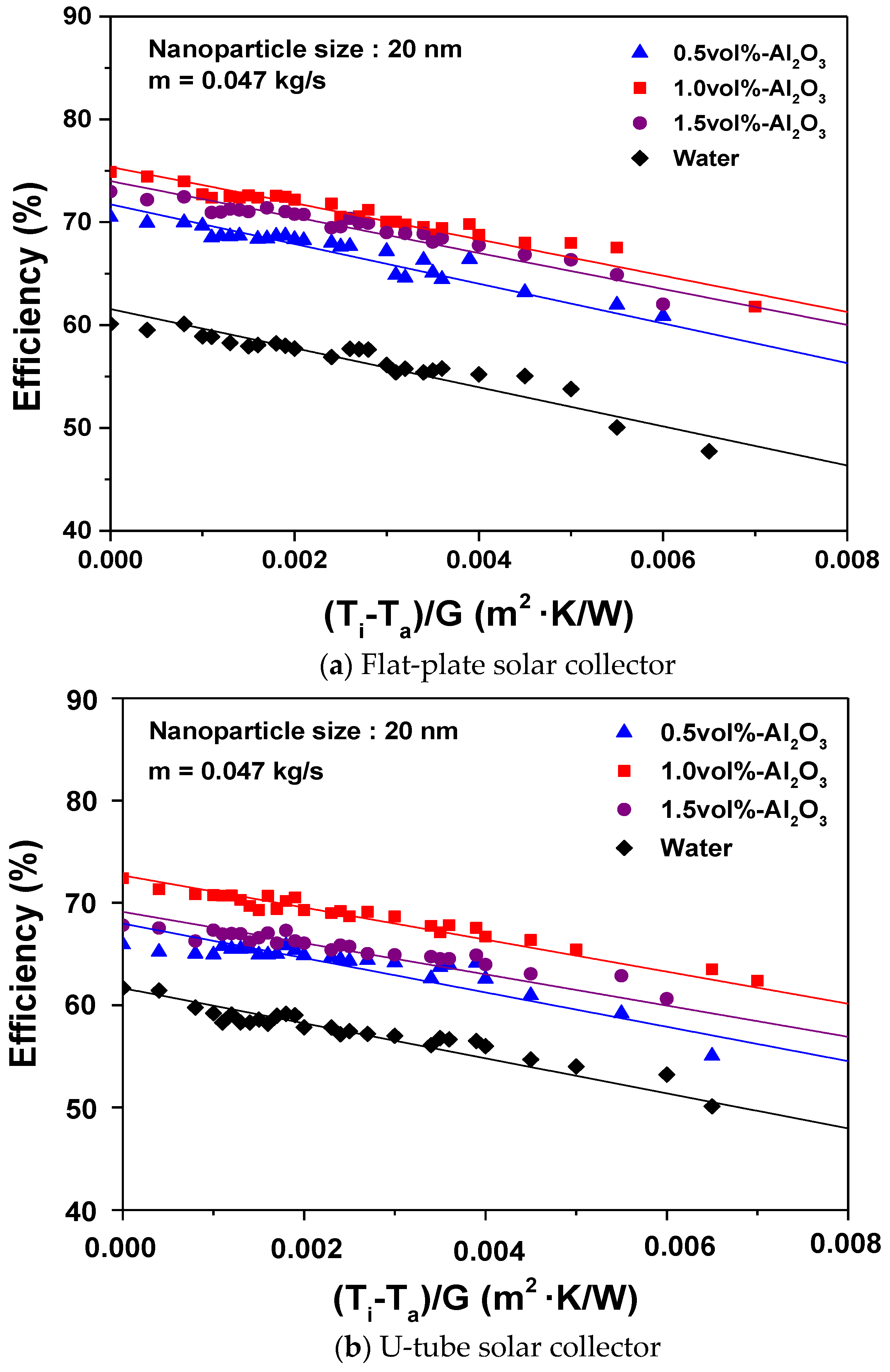
Figure 4 shows the efficiency variation of the flat-plate and U-tube solar collectors according to the concentration of the Al2O3 nanofluid. The nanoparticle size was fixed to 20 nm because this size demonstrated the highest efficiencies of the solar collectors when the mass flow rate of the working fluids was 0.047 kg/s. The efficiencies of the solar collectors using the Al2O3 nanofluid were significantly higher than those of the solar collectors using water. In the case of the flat-plate solar collector, the highest efficiency of the solar collector was 74.9% at Ti = Ta and an Al2O3 nanofluid concentration of 1.0 vol %. This was a 19.7% higher efficiency than that using water, and it was 5.9% and 2.5% higher than those at the concentrations of 0.5 vol % and 1.5 vol %, respectively. In the case of the U-tube solar collector, the highest efficiency was 72.4% at the concentration of 1.0% vol. This was 14.8% higher than that using water. Moreover, the efficiency of the U-tube solar collector at the concentration of 1.0 vol % was 8.9% and 6.4% higher than those of the 0.5 vol %- and 1.5 vol %-Al2O3 nanofluids, respectively. For the experimental results, the solar collectors showed a maximum efficiency at the concentration of Al2O3 nanofluid of 1.0 vol %. In a previous study [30,31,32], the efficiency of the solar collector increased with the increase of the thermal conductivity of the nanofluid. However, in this study, the efficiency of the solar collector at the concentration of 1.5 vol % was less than that at the concentration of 1.0 vol %. The effect of thermal conductivity on the thermal performance of the solar collector was significant; however, additional factors affected the performance of the solar collector. As shown in Figure 4, even though the thermal conductivity at the concentration of 1.5 vol % was higher than that of 1.0 vol %, the dispersion stability of the nanoparticles was not ensured because the dispersion stability decreased with the increase of the concentration of the nanofluid. Moreover, the heat transfer and thermal absorption decreased owing to the increase of the viscosity. Therefore, the efficiency of the solar collector at the concentration of 1.5 vol % was less than that at the Al2O3 concentration of 1.0 vol %.
The highest efficiency for the two types of solar collectors was achieved with the Al2O3 nanoparticle size of 20 nm and the Al2O3 nanofluid concentration of 1.0 vol %. In this study, the 1.0 vol %-Al2O3 nanofluid with the Al2O3 nanoparticle size of 20 nm was used as the working fluid in two types of solar collectors for one year in Gwangju, Korea. The energy savings were calculated and compared when water was used in the two solar collectors under the same operating conditions. The solar radiation and average ambient temperature in a month in Gwangju, Korea, are listed in Table 4. Based on the experimental results, an economic analysis on the use of the solar collectors in various countries was performed. In the world, many power plants are operated by using coal. Thus, coal-fired power plants were selected for the comparison of energy and pollution in this study. When 1 kg of coal is burned, 29.306 MJ of energy can be generated, and concurrently, greenhouse gases, such as CO2 and SO2, are released. The CO2 and SO2 generated per 1 kg of coal burned are 2.93 kg and 0.0123 kg, respectively [33,34].
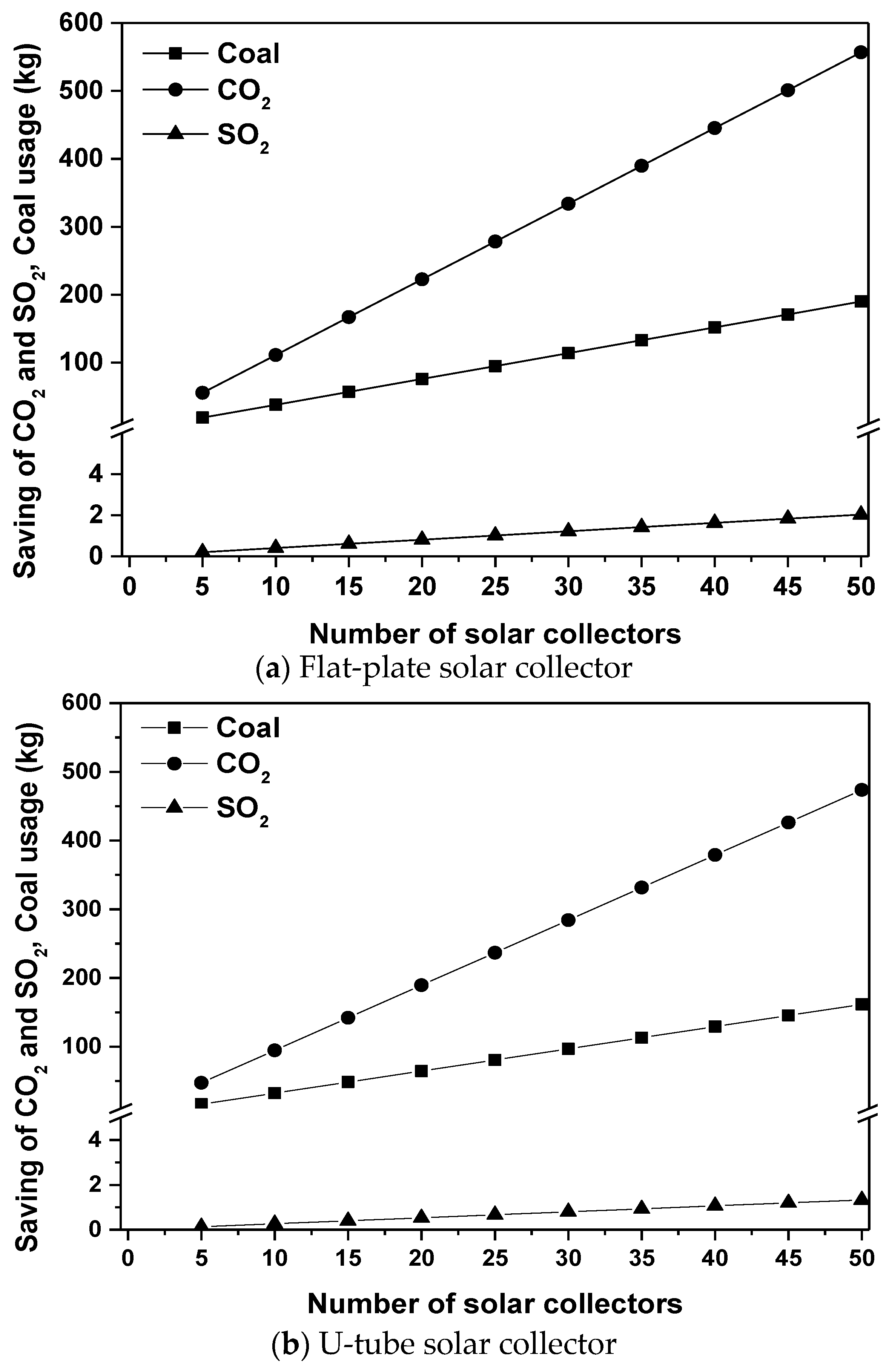
Figure 5 shows the reduction in coal use and the amount of generated CO2 and SO2 when the 1.0 vol %-Al2O3 nanofluid with 20-nm nanoparticles was used in the flat-plate and U-tube solar collectors in Korea. The results were compared to those of solar collectors using water. The heat amounts obtained from the solar collectors using Al2O3 nanofluid compared to those using water during one year were calculated, and the results were converted to the reduction of coal used and the CO2 and SO2 generated. Since a solar heat system uses several solar collectors, the reduction of the CO2 and SO2 generated was calculated depending on the number of solar collectors. When 50 EA flat-plate solar collectors were applied under the given conditions, the amount of coal used and the CO2 and SO2 generated was 189.99 kg, 556.69 kg, and 2.03 kg, respectively, less than those using water. When 50 EA U-tube solar collectors were used under the given conditions, the amount of coal used and the CO2 and SO2 generated was 161.65 kg, 473.65 kg, and 1.33 kg, respectively, less than those of solar collectors using water. For the flat-plate solar collector, the amount of coal used and the CO2 and SO2 generated was 28.34 kg, 83.04 kg, and 0.7 kg, respectively, less than those of solar collectors using the U-tube solar collector.
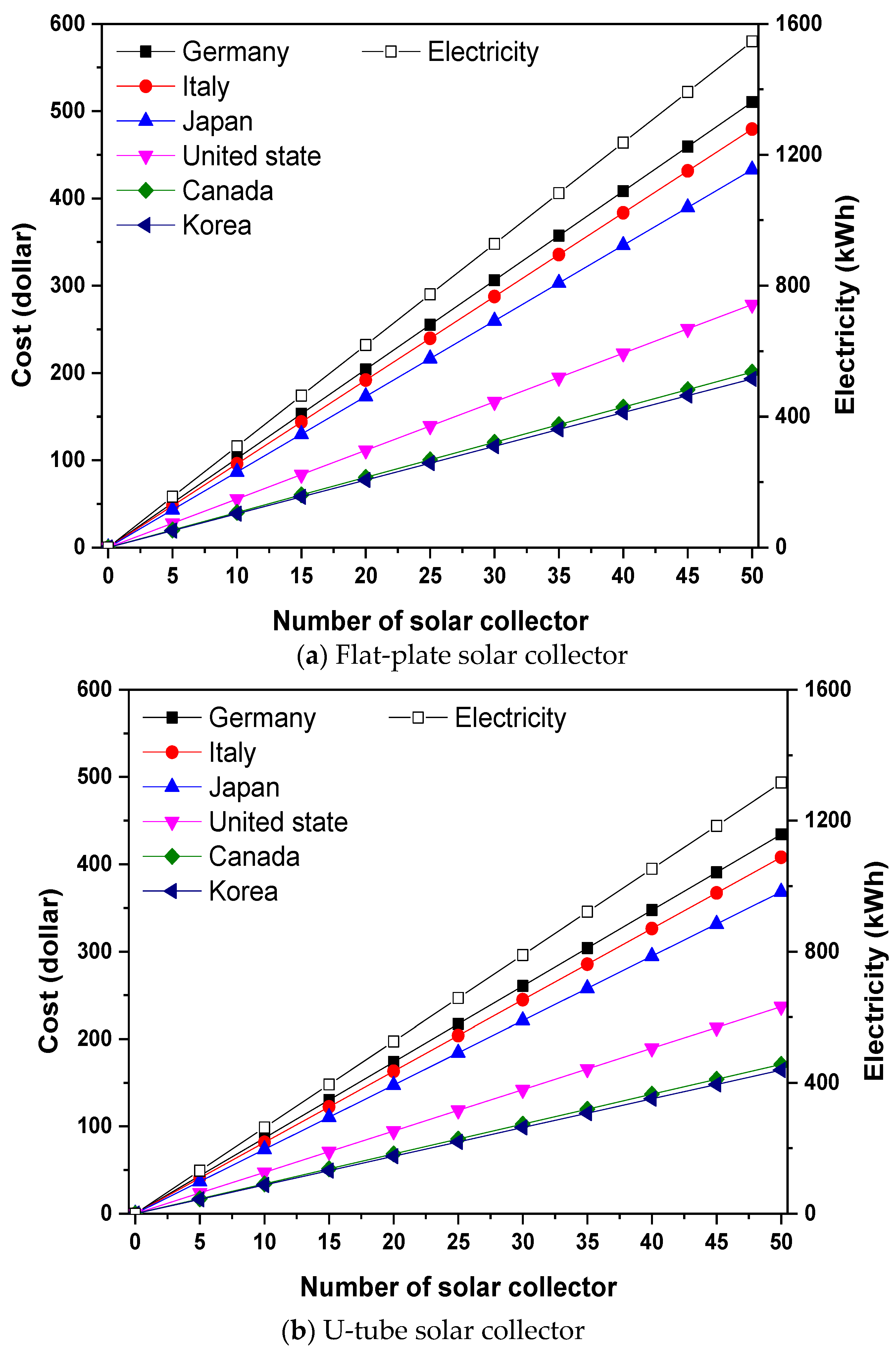
Figure 6 shows the reduction of the electricity and electrical cost for various countries when the 20 nm-Al2O3 nanoparticles and 1.0 vol %-Al2O3 nanofluid were used in the solar collectors for one year. For the efficiency of a standard power plant, 1 kg of coal generates 8.14 kWh of electricity [35]. When the Al2O3 nanofluid was used in 50 EA flat-plate solar collectors, the amount of electricity generated in one year was 1546.6 kWh less than that using water. Six representative countries were selected to compare the electric cost in each country, and its location is presented in Table 5. Germany had the largest reduction in electricity cost at 510.4 U.S. dollars, while the lowest reduction of electricity cost was in Korea at 193.3 dollars. In addition, when 50 EA U-tube solar collectors with the Al2O3 nanofluid were used for one year, the amount of electricity generated was 1315.9 kWh less than that with water. Thus, the highest electricity cost reduction was in Germany at 434.2 dollars, while the lowest cost reduction was in Korea.
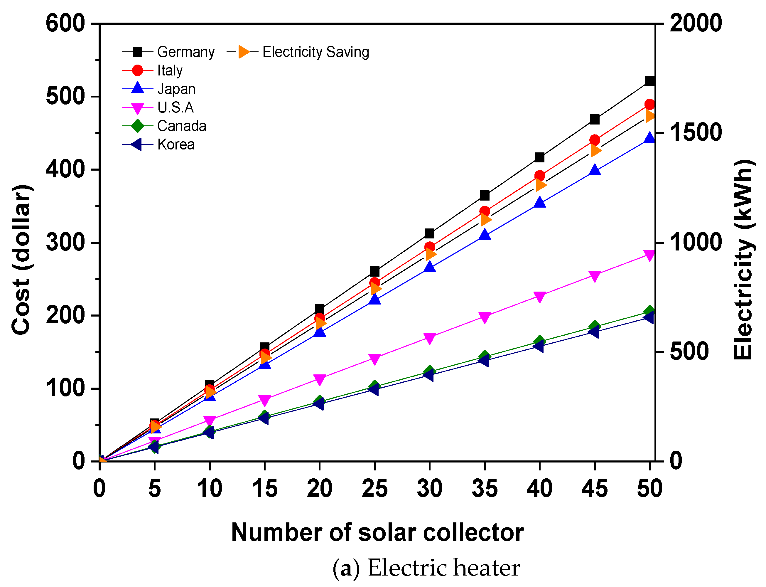
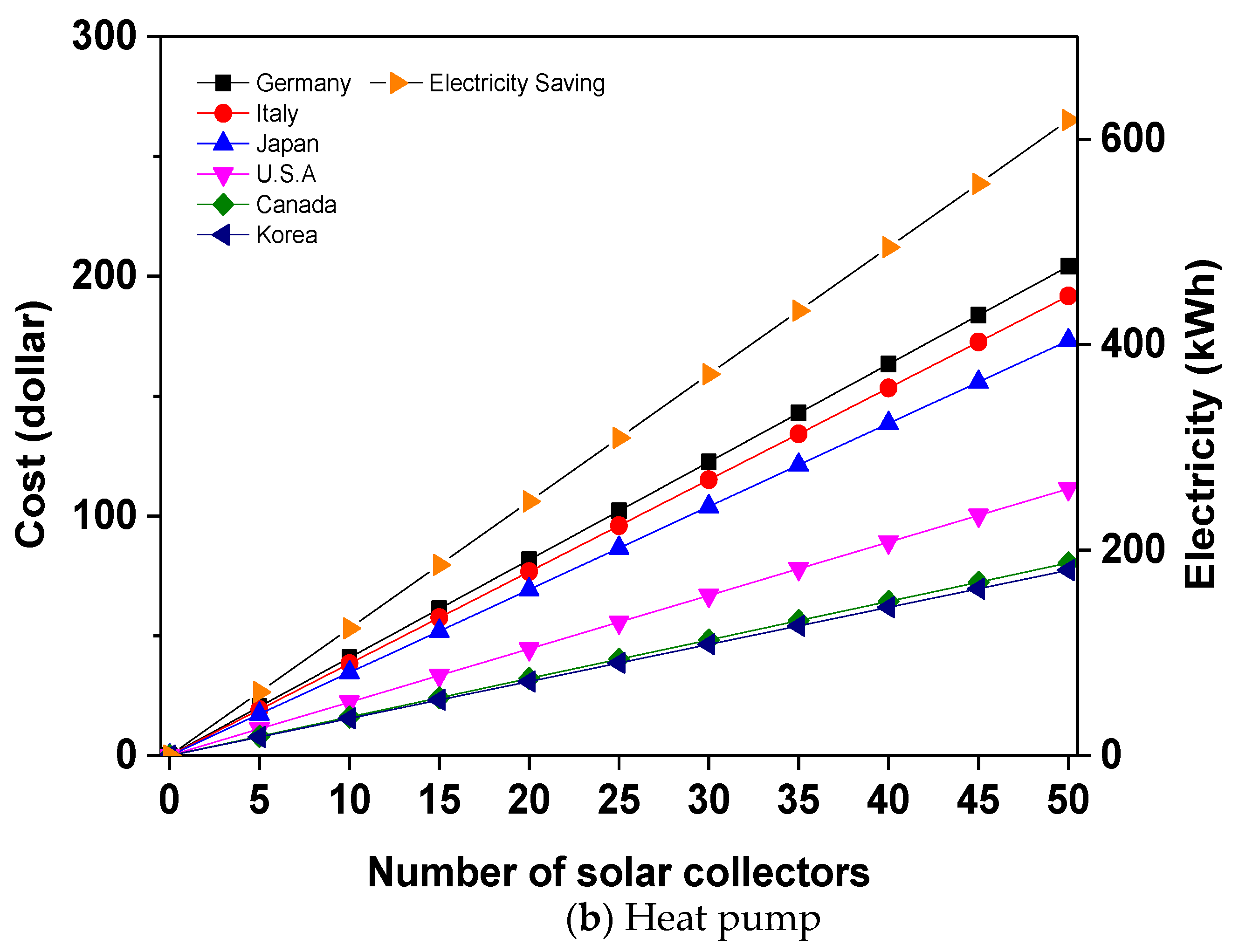
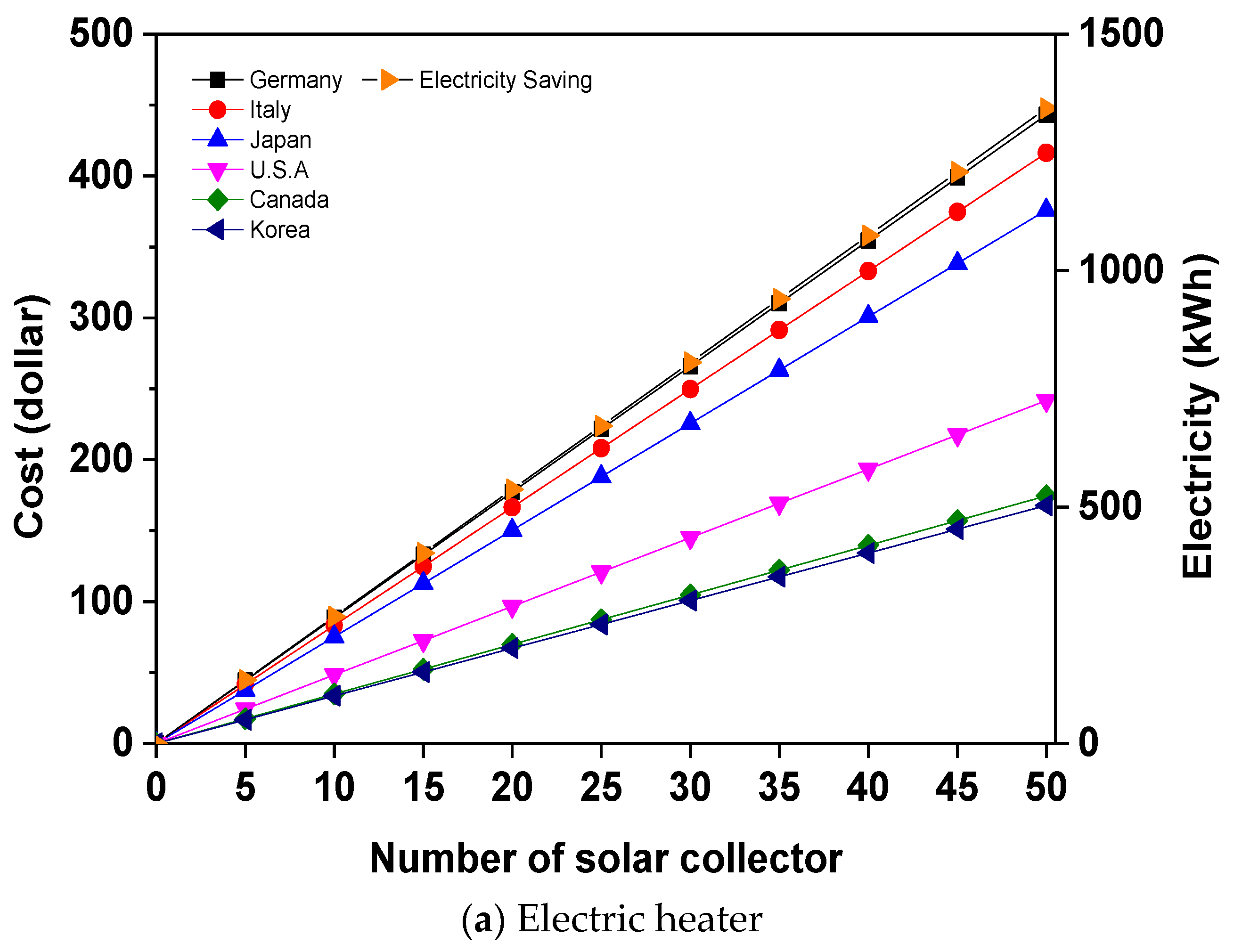
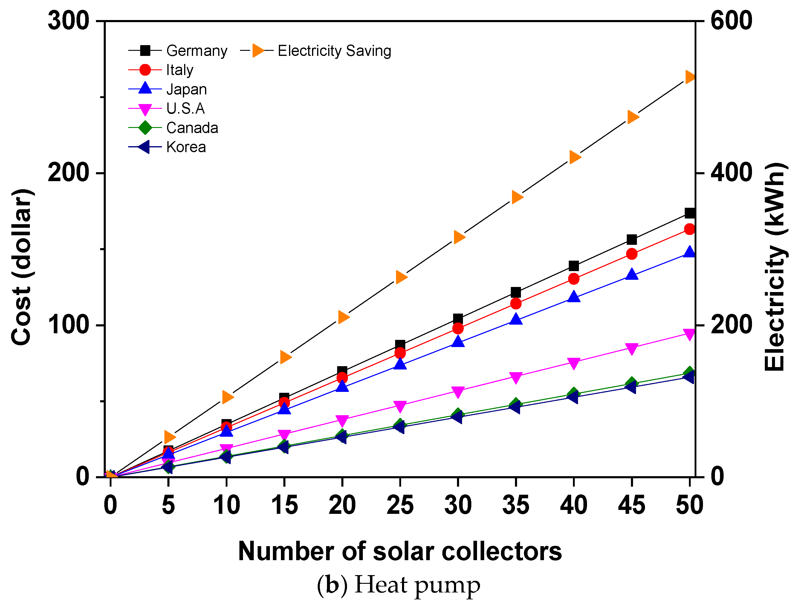
When the Al2O3 nanofluid and water were used in the solar collectors, the amount of electricity and electrical cost savings were calculated as shown in Figure 6. To compare these results with other heating systems that are used widely for residential heating, the electricity and electrical cost savings in various countries were calculated and compared to those of solar collectors using an electric heater and heat pump. In this study, the average COP (coefficient of performance) of an electric heater and a heat pump was assumed to be 0.97 and 2.5 for one year, respectively [36]. Figure 7 shows the electricity and electrical cost savings based on the number of flat-plate solar collectors when the electric heater and heat pump were used to produce a heat energy equal to the energy savings in the solar collector by applying the Al2O3 nanofluid compared to that of a solar collector using water. The electricity saving, which is from the use of 50 EA flat-plate solar collectors, is replaced by using the electric heater, and 1578.1 kWh of electricity can be saved, as shown in Figure 7a. Under this condition, it was estimated that Germany had the largest reduction in electricity cost at 520.8 dollars. For the heat pump system, 441.8 kWh of electricity was saved, as shown in Figure 7b. Under this condition, Germany had the largest reduction of electricity cost at 204.1 dollars.
Figure 8 shows the electricity and electricity cost savings depending on the number of U-tube solar collectors when the electric heater and heat pump were used to produce heat energy equal to the energy saving in the U-tube solar collector using the 1.0 vol %-Al2O3 nanofluid with 20-nm nanoparticles. Figure 8a shows that 1342.7 kWh of electricity was saved when using the Al2O3 nanofluid in the 50 EA U-tube solar collectors that was replaced by the electric heater. Thus, Germany had the largest reduction in electricity costs at 443.1 dollars per year. For the heat pump system, 526.4 kWh of electricity was saved, as shown in Figure 8b. Under this condition, it was estimated that Germany had the largest reduction in electricity cost at 173.7 dollars.
4. Conclusions
In this study, the thermal efficiencies of flat-plate and U-tube solar collectors were investigated experimentally when Al2O3 nanofluid and water were used as the working fluids. The performance of a solar collector was measured according to the Al2O3 nanoparticle size and Al2O3 nanofluid concentration, and it was compared to that using water. Based on the experimental results, the reduction in coal use, amount of CO2 and SO2 generated, magnitude of electricity, and electricity cost for various countries were calculated and investigated.
As a result, as the concentration of the Al2O3 nanofluid increased, the performance improved. The highest efficiency for the solar collectors occurred at the Al2O3 concentration of 1.0 vol % with the nanoparticle size of 20 nm. The maximum efficiency of the flat-plate and U-tube solar collectors using a 1.0 vol %-Al2O3 nanofluid with 20-nm nanoparticles was 74.9% and 72.4%, respectively, when (Ti − Ta)/G = 0. For wide operating conditions, the two types of solar collectors had improved performance compared to that using water. The performance improvement of the flat-plate and U-tube solar collectors using the Al2O3 nanofluid was 14.8% and 10.7%, respectively, compared to that using water.
For the efficiency improvement using the Al2O3 nanofluid, when 50 EA flat-plate solar collectors were operated for one year using a 1.0 vol %-Al2O3 nanofluid with 20-nm nanoparticles, the coal used and CO2 and SO2 generated were 189.99 kg, 556.69 kg, and 2.03 kg, respectively, less than those using water. Thus, the electricity was reduced by 1546.56 kWh, and the electricity cost was reduced by 510.4 U.S. dollars in Germany. For the U-tube solar collector, the amount of electricity generated was 1315.9 kWh less than that using water. Thus, the largest electricity cost reduction was in Germany at 434.2 U.S. dollars. In addition, the electricity and electricity cost savings for various countries were calculated when the same heat load was replaced by using an electric heater and a heat pump. It was predicted to save up to 1342 kWh of electricity and 443.1 U.S. dollars of electricity cost in Germany when the electric heater was used. For the heat pump, 526.4 kWh of electricity and 173.7 U.S. dollars of electricity cost in Germany could be saved.
Acknowledgments
This work was supported by the “Human Resources Program in Energy Technology” of the Korea Institute of Energy Technology Evaluation and Planning (KETEP), granted financial resource from the Ministry of Trade, Industry, and Energy, Republic of Korea (No. 20174030201620), and the Basic Science Research Program through the National Research Foundation of Korea (NRF) funded by the Ministry of Science, ICT, and Future Planning (NRF-2017R1A2B4006125).
Author Contributions
Honghyun Cho provided the main idea of the study; Woobin Kang and Yunchan Shin designed and performed the experiments; Woobin Kang analyzed the data; Honghyun Cho wrote the paper.
Conflicts of Interest
The authors declare no conflict of interest.
References
- Ahmadu, T.O.; Folayan, C.O.; Anafi, F.O. Modeling, Simulation and Optimization of a Solar Absorption Air Conditioning System for an Office Block in Zaria, Nigeria. Int. J. Air-Cond. Refrig. 2016, 24, 1650012. [Google Scholar] [CrossRef]
- Khaldi, S.; Korti, A.I.N.; Abboudi, S. Improving the Airflow Distribution within an Indirect Solar Dryer by Modifications Based on Computational Fluid Dynamics. Int. J. Air-Cond. Refrig. 2017, 25, 1750022. [Google Scholar] [CrossRef]
- Mahian, O.; Kianifar, A.; Sahin, A.Z.; Wongwises, S. Performance analysis of a minichannel-based solar collector using different nanofluids. Energy Convers. Manag. 2014, 88, 129–138. [Google Scholar] [CrossRef]
- Hemmat Esfe, M.; Saedodin, S.; Mahian, O.; Wongwises, S. Thermophysical properties, heat transfer and pressure drop of COOH-functionalized multi walled carbon nanotubes/water nanofluids. Int. Commun. Heat Mass Transf. 2014, 58, 176–183. [Google Scholar] [CrossRef]
- Pryazhnikov, M.I.; Minakov, A.V.; Rudyak, V.Y.; Guzei, D.V. Thermal conductivity measurements of nanofluids. Int. Commun. Heat Mass Transf. 2017, 104, 1275–1282. [Google Scholar] [CrossRef]
- Charab, A.A.; Movahedirad, S.; Norouzbeigi, R. Thermal conductivity of Al2O3 + TiO2/water nanofluid: Model development and experimental validation. Appl. Therm. Eng. 2017, 119, 42–51. [Google Scholar] [CrossRef]
- Lee, J.K.; Koo, J.; Hong, H.; Kang, Y.T. The effects of nanoparticles on absorption heat and mass transfer performance in NH3/H2O binary nanofluids. Int. J. Refrig. 2010, 33, 269–275. [Google Scholar] [CrossRef]
- Verma, S.K.; Tiwari, A.K.; Chauhan, D.S. Experimental evaluation of flat plate solar collector using nanofluids. Energy Convers. Manag. 2017, 134, 103–115. [Google Scholar] [CrossRef]
- Moghadam, A.J.; Farzane-Gord, M.; Sajadi, M.; Hoseyn-Zadeh, M. Effects of CuO/water nanofluid on the efficiency of a flat-plate solar collector. Exp. Therm. Fluid Sci. 2014, 58, 9–14. [Google Scholar] [CrossRef]
- Noghrehabadi, A.; Hajidavaloo, E.; Moravej, M. Experimental investigation of efficiency of square flat-plate solar collector using SiO2/water nanofluid. Case Stud. Therm. Eng. 2016, 8, 378–386. [Google Scholar] [CrossRef]
- Yousefi, T.; Veysi, F.; Shojaeizadeh, E.; Zinadini, S. An experimental investigation on the effect of Al2O3–H2O nanofluid on the efficiency of flat-plate solar collectors. Renew. Energy 2012, 39, 293–298. [Google Scholar] [CrossRef]
- Montoya-Marquez, O.; Flores-Prieto, J. The Effect of the Angle of Inclination on the Efficiency in a Medium-Temperature Flat Plate Solar Collector. Energies 2017, 10, 71. [Google Scholar] [CrossRef]
- Ge, Z.; Wang, H.; Wang, H.; Zhang, S.; Guan, X. Exergy Analysis of Flat Plate Solar Collectors. Entropy 2014, 16, 2549–2567. [Google Scholar] [CrossRef]
- Verma, S.K.; Tiwari, A.K.; Chauhan, D.S. Performance augmentation in flat plate solar collector using MgO/water nanofluid. Energy Convers. Manag. 2016, 124, 607–617. [Google Scholar] [CrossRef]
- Shojaeizadeh, E.; Veysi, F. Development of a correlation for parameter controlling using exergy efficiency optimization of an Al2O3/water nanofluid based flat-plate solar collector. Appl. Therm. Eng. 2016, 98, 1116–1129. [Google Scholar] [CrossRef]
- Said, Z.; Sajid, M.H.; Alim, M.A.; Saidur, R.; Rahim, N.A. Experimental investigation of the thermophysical properties of Al2O3-nanofluid and its effect on a flat plate solar collector. Int. Commun. Heat Mass Transf. 2013, 48, 99–107. [Google Scholar] [CrossRef]
- Zamzamian, A.; KeyanpourRad, M.; KianiNeyestani, M.; Jamal-Abad, M.T. An experimental study on the effect of Cu-synthesized/EG nanofluid on the efficiency of flat-plate solar collectors. Renew. Energy 2014, 71, 658–664. [Google Scholar] [CrossRef]
- Said, Z.; Sabiha, M.A.; Saidur, R.; Hepbasli, A.; Rahim, N.A.; Mekhilef, S.; Ward, T.A. Performance enhancement of a Flat Plate Solar collector using Titanium dioxide nanofluid and Polyethylene Glycol dispersant. J. Clean. Prod. 2015, 92, 343–353. [Google Scholar] [CrossRef]
- Ghaderian, J.; Sidik, N.A.C. An experimental investigation on the effect of Al2O3/distilled water nanofluid on the energy efficiency of evacuated tube solar collector. Int. J. Heat Mass Transf. 2017, 108, 972–987. [Google Scholar] [CrossRef]
- Sabiha, M.A.; Saidur, R.; Hassani, S.; Said, Z.; Mekhilef, S. Energy performance of an evacuated tube solar collector using single walled carbon nanotubes nanofluids. Energy Convers. Manag. 2015, 105, 1377–1388. [Google Scholar] [CrossRef]
- Iranmanesh, S.; Ong, H.C.; Ang, B.C.; Sadeghinezhad, E.; Esmaeilzadeh, A.; Mehrali, M. Thermal performance enhancement of an evacuated tube solar collector using graphene nanoplatelets nanofluid. J. Clean. Prod. 2017, 162, 121–129. [Google Scholar] [CrossRef]
- Delfani, S.; Karami, M.; Behabadi, M.A.A. Performance characteristics of a residential-type direct absorption solar collector using MWCNT nanofluid. Renew. Energy 2016, 87, 754–764. [Google Scholar] [CrossRef]
- Menbari, A.; Alemrajabi, A.A.; Rezaei, A. Heat transfer analysis and the effect of CuO/Water nanofluid on direct absorption concentrating solar collector. Appl. Therm. Eng. 2016, 104, 176–183. [Google Scholar] [CrossRef]
- Karami, M.; Akhavan-Bahabadi, M.A.; Delfani, S.; Raisee, M. Experimental investigation of CuO nanofluid-based Direct Absorption Solar Collector for residential applications. Renew. Sustain. Energy Rev. 2015, 52, 793–801. [Google Scholar] [CrossRef]
- Gorji, T.B.; Ranjbar, A.A. Thermal and exergy optimization of a nanofluid-based direct absorption solar collector. Renew. Energy 2017, 106, 274–287. [Google Scholar] [CrossRef]
- Hatami, M.; Mosayebidorcheh, S.; Jing, D. Thermal performance evaluation of alumina-water nanofluid in an inclined direct absorption solar collector (IDASC) using numerical method. J. Mol. Liq. 2017, 231, 632–639. [Google Scholar] [CrossRef]
- Chen, L.; Liu, J.; Fang, X.; Zhang, Z. Reduced graphene oxide dispersed nanofluids with improved photo-thermal conversion performance for direct absorption solar collectors. Sol. Energy Mater. Sol. Cells 2017, 163, 125–133. [Google Scholar] [CrossRef]
- Turkyilmazoglu, M. Performance of direct absorption solar collector with nanofluid mixture. Energy Convers. Manag. 2016, 114, 1–10. [Google Scholar] [CrossRef]
- Moffat, R.J. Using Uncertainty Analysis in the Planning of an Experiment. J. Fluids Eng. 1985, 107, 173–178. [Google Scholar] [CrossRef]
- Kim, H.; Kim, J.; Cho, H. Experimental study on performance improvement of U-tube solar collector depending on nanoparticle size and concentration of Al2O3 nanofluid. Energy 2017, 118, 1304–1312. [Google Scholar] [CrossRef]
- Kim, H.; Kim, J.; Cho, H. Review of Thermal Performance and Efficiency in Evacuated Tube Solar Collector with Various Nanofluids. Int. J. Air-Cond. Refrig. 2017, 25, 1730001. [Google Scholar] [CrossRef]
- Tong, Y.; Cho, H. Comparative Study on the Thermal Performance of Evacuated Solar Collectors with U-Tubes and Heat Pipes. Int. J. Air-Cond. Refrig. 2015, 23, 1550019. [Google Scholar] [CrossRef]
- Hong, B.D.; Slatick, E.R. Carbon Dioxide Emission Factors for Coal; U.S. Energy Information Administration (eia). Available online: https://www.eia.gov/coal/production/quarterly/co2_article/co2.html (accessed on 20 November 2017).
- Goldemberg, J. Interactions: Energy/Environment; EOLSS Publications: Oxford, UK, 2009; pp. 1–426. [Google Scholar]
- Unit Juggler Convert Everything with Ease. Available online: https://www.unitjuggler.com/convert-energy-from-kgSKE-to-kWh.html (accessed on 20 November 2017).
- Hubbard, R. Water-to-water heat pump. ASHRAE J. 2009, 51, 28–35. [Google Scholar]
Figure 1.
Configuration of experimental apparatus.

Figure 2.
SEM micrograph of the Al2O3 nanoparticles: (a) 20 nm; (b) 50 nm; (c)100 nm.

Figure 3.
Efficiency variations in the solar collector for various nanoparticle sizes: (a) Flat-plate solar collector; (b) U-tube solar collector.
Figure 3.
Efficiency variations in the solar collector for various nanoparticle sizes: (a) Flat-plate solar collector; (b) U-tube solar collector.


Figure 4.
Efficiency variations in the solar collector for various nanofluid concentrations: (a) Flat-plate solar collector; (b) U-tube solar collector.
Figure 4.
Efficiency variations in the solar collector for various nanofluid concentrations: (a) Flat-plate solar collector; (b) U-tube solar collector.

Figure 5.
Coal use and CO2 and SO2 savings depending on the number of solar collectors (Al2O3 size: 20 nm, concentration: 1.0 vol %): (a) Flat-plate solar collector; (b) U-tube solar collector.
Figure 5.
Coal use and CO2 and SO2 savings depending on the number of solar collectors (Al2O3 size: 20 nm, concentration: 1.0 vol %): (a) Flat-plate solar collector; (b) U-tube solar collector.

Figure 6.
Electricity and electricity cost saving depending on the number of solar collectors (Al2O3 size: 20 nm, Concentration: 1.0 vol %): (a) Flat-plate solar collector; (b) U-tube solar collector.
Figure 6.
Electricity and electricity cost saving depending on the number of solar collectors (Al2O3 size: 20 nm, Concentration: 1.0 vol %): (a) Flat-plate solar collector; (b) U-tube solar collector.

Figure 7.
Electricity and electricity cost of the electric heater and heat pump using a flat-plate solar collector: (a) Electric heater; (b) Heat pump.
Figure 7.
Electricity and electricity cost of the electric heater and heat pump using a flat-plate solar collector: (a) Electric heater; (b) Heat pump.


Figure 8.
Electricity and electricity cost of the electric heater and heat pump using a U-tube solar collector: (a) Electric heater; (b) Heat pump.
Figure 8.
Electricity and electricity cost of the electric heater and heat pump using a U-tube solar collector: (a) Electric heater; (b) Heat pump.


Table 1.
Uncertainties in the measuring equipment.
| Parameter | Type | Range | Accuracy |
|---|---|---|---|
| Thermocouple | T-type | −200 °C–300 °C | ±0.75% |
| Solar radiation sensor | Silicon pyranometer | 0–2000 W/m2 | ±1.95% |
| Mass flow meter | - | 0–1.4 m3/h | ±0.5% |
| Data logger | - | - | ±100 ppm |
Table 2.
Specifications of the solar collectors.
| Parameter | Flat-Plate Solar Collector | U-Tube Solar Collector |
|---|---|---|
| Collector length (mm) | 2000 | 1445 |
| Collector width (mm) | 1000 | 1640 |
| Gross area (m2) | 2.00 | 2.37 |
| Weight (kg) | 36 | 51.5 |
| Riser tube material | Copper | Copper |
| Inner diameter of pipes (mm) | 8 | 10 |
| Outer diameter of pipes (mm) | 8.8 | 15 |
| Absorptivity of absorber coating | 0.95 | 0.95 |
Table 3.
Experimental conditions.
| Item | Conditions |
|---|---|
| Nanoparticle type/Basic fluid | Al2O3/Water |
| Nanoparticle size (nm) | 20, 50, 100 |
| Nanofluid concentration (vol %) | 0.5, 1.0, 1.5 |
| Mass flow rate (kg/s) | 0.047 |
| Solar radiation (W/m2) | 47–792 |
| Experiment time | 10:00 a.m. to 5:00 p.m |
Table 4.
Solar radiation and average environmental temperature in a month (Gwangju, Korea).
| Month | Solar Radiation (MJ/m2/Month) | Ambient Temperature (°C) |
|---|---|---|
| 1 | 259.40 | 1.1 |
| 2 | 326.58 | 2.9 |
| 3 | 442.65 | 7.3 |
| 4 | 529.35 | 13.3 |
| 5 | 579.96 | 18.4 |
| 6 | 501.86 | 22.5 |
| 7 | 456.10 | 25.7 |
| 8 | 462.36 | 26.2 |
| 9 | 425.78 | 22.1 |
| 10 | 401.83 | 16.0 |
| 11 | 286.21 | 9.3 |
| 12 | 240.73 | 3.3 |
Table 5.
The latitude and longitude of representative cities and countries.
| Country (City) | Latitude | Longitude |
|---|---|---|
| U.S.A. (Washington, D.C.) | 38°54′21.1′′ N | 77°02′09.1′′ W |
| Germany (Berlin) | 52°31′14.6′′ N | 13°24′04.9′′ E |
| Italy (Rome) | 41°54′02.8′′ N | 12°29′33.8′′ E |
| Japan (Tokyo) | 35°43′29.8′′ N | 139°43′51.8′′ E |
| Canada (Ottawa) | 45°24′11.8′′ N | 75°41′55.5′′ W |
| Korea (Gwangju) | 35°08′34.1′′ N | 126°56′05.1′′ E |
© 2017 by the authors. Licensee MDPI, Basel, Switzerland. This article is an open access article distributed under the terms and conditions of the Creative Commons Attribution (CC BY) license (http://creativecommons.org/licenses/by/4.0/).
Share and Cite
MDPI and ACS Style
Kang, W.; Shin, Y.; Cho, H. Economic Analysis of Flat-Plate and U-Tube Solar Collectors Using an Al2O3 Nanofluid. Energies 2017, 10, 1911. https://doi.org/10.3390/en10111911
AMA Style
Kang W, Shin Y, Cho H. Economic Analysis of Flat-Plate and U-Tube Solar Collectors Using an Al2O3 Nanofluid. Energies. 2017; 10(11):1911. https://doi.org/10.3390/en10111911
Chicago/Turabian StyleKang, Woobin, Yunchan Shin, and Honghyun Cho. 2017. "Economic Analysis of Flat-Plate and U-Tube Solar Collectors Using an Al2O3 Nanofluid" Energies 10, no. 11: 1911. https://doi.org/10.3390/en10111911
Note that from the first issue of 2016, this journal uses article numbers instead of page numbers. See further details here.