Design and Performance Analysis of a Coal Bed Gas Drainage Machine Based on Incomplete Non-Circular Gears

School of Mechanical and Electrical Engineering, China University of Mining & Technology, Xuzhou 221116, China
*
Author to whom correspondence should be addressed.
Energies 2017, 10(12), 1933; https://doi.org/10.3390/en10121933
Submission received: 16 October 2017
/
Revised: 11 November 2017
/
Accepted: 17 November 2017
/
Published: 23 November 2017
Abstract
:In order to solve the problem of reciprocating motion in no beam supported mining machines, putting energy saving as a starting point in Coal Bed Methane (CBM) exploitation, this paper designs a completely non-circular gear automatic reversing vertical drainage machine based on the theory of non-circular gear transmission. In the field of CBM exploitation, the use of non-circular gears is an attempt at an innovation. First of all, according to the working conditions of the pump and use requirements, a scheme is established whereby the one-way rotary motion of the motor is changed into reciprocating motion so that it could drive the oil pumping rod to achieve the upper and lower mining. Secondly, this paper has designed a new type non-circular gear reversing box as the core component to replace the traditional four beam linkage mechanism and also provides elaborate calculations. Finally, the movement simulation of the non-circular gear reversing gear system is completed. Comparing the motion simulation results with the theoretical ones, the correctness of our theoretical analysis can be verified. Compared with the traditional devices, the new coal seam gas drainage machine model design has nearly 11% higher efficiency, which has obvious energy saving effects and reduces the cost of mining coal seam gas.
1. Introduction
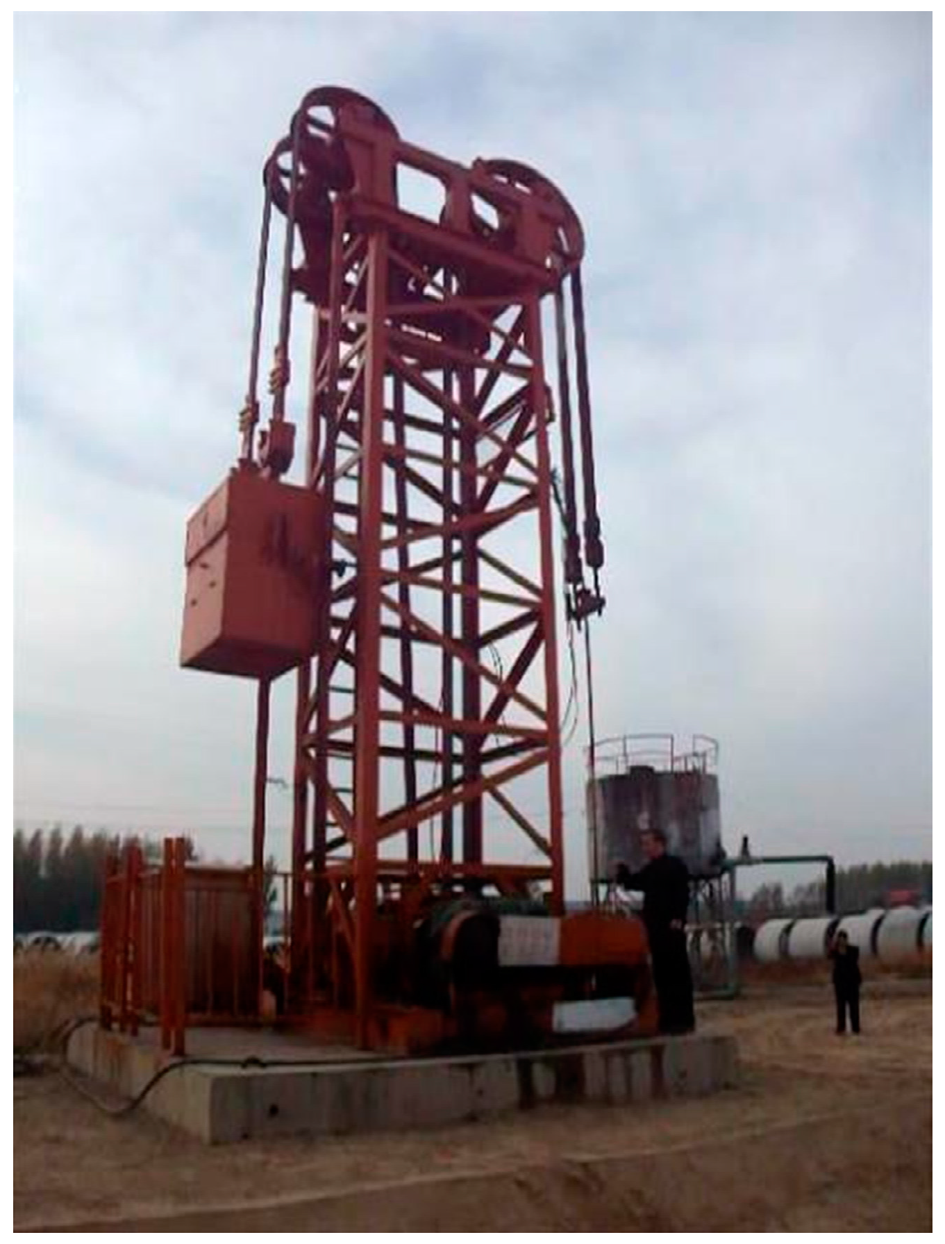
Chinese coal bed methane resources are relatively rich and concentrated which makes their exploitation a relatively new clean coal industry in the world [1]. The exploitation technology of coal bed methane is largely based on the oil field experience, so the traditional beam pumping unit is still used in most of the equipment, as shown in Figure 1. Feng [2] analyzed the main defects of the beam pumping unit according to its working conditions. The main one is that beam pumping units use crank rocker mechanisms, which leads to their poor adaptability. When encountering some special coal seam gas, the overall size of the pumping unit needs to be adjusted to change the stroke, which seriously affects the efficiency of CBM exploitation. The low efficiency of the beam pumping unit is another reason and the energy waste of the pumping unit is very serious. Li and Fan [3], and Fu [4] have made some adjustments and improvements on the basis of the conventional beam drainage machine appeared the specific. However, Liu [5] and Fan [6] argue that this cannot solve the fundamental drawbacks of the crank rocker mechanism improving performance in a relatively small range and the poor adaptability and low working efficiency shortcomings of beam pumping will still exist. Based on this series of drawbacks, all kinds of new non-walking beam drainage machine have emerged. At present, Li [7], Liu [8] and Qi [9] have all done a lot of research on these machines which can be roughly divided into two types according to the switching mode, namely mechanical reversing and motor reversing. Niu [10] and Shao [11] have studied the typical chain drainage machine as an example of a non-beam mechanical reversing device, as shown in Figure 2. The utility model has the advantages of good balance performance, convenient adjustment balance, small side force when reversing and working and light weight. The disadvantage is that it has more moving parts, an unsealed gas balance system and it can lose load protection leading to a higher failure rate.
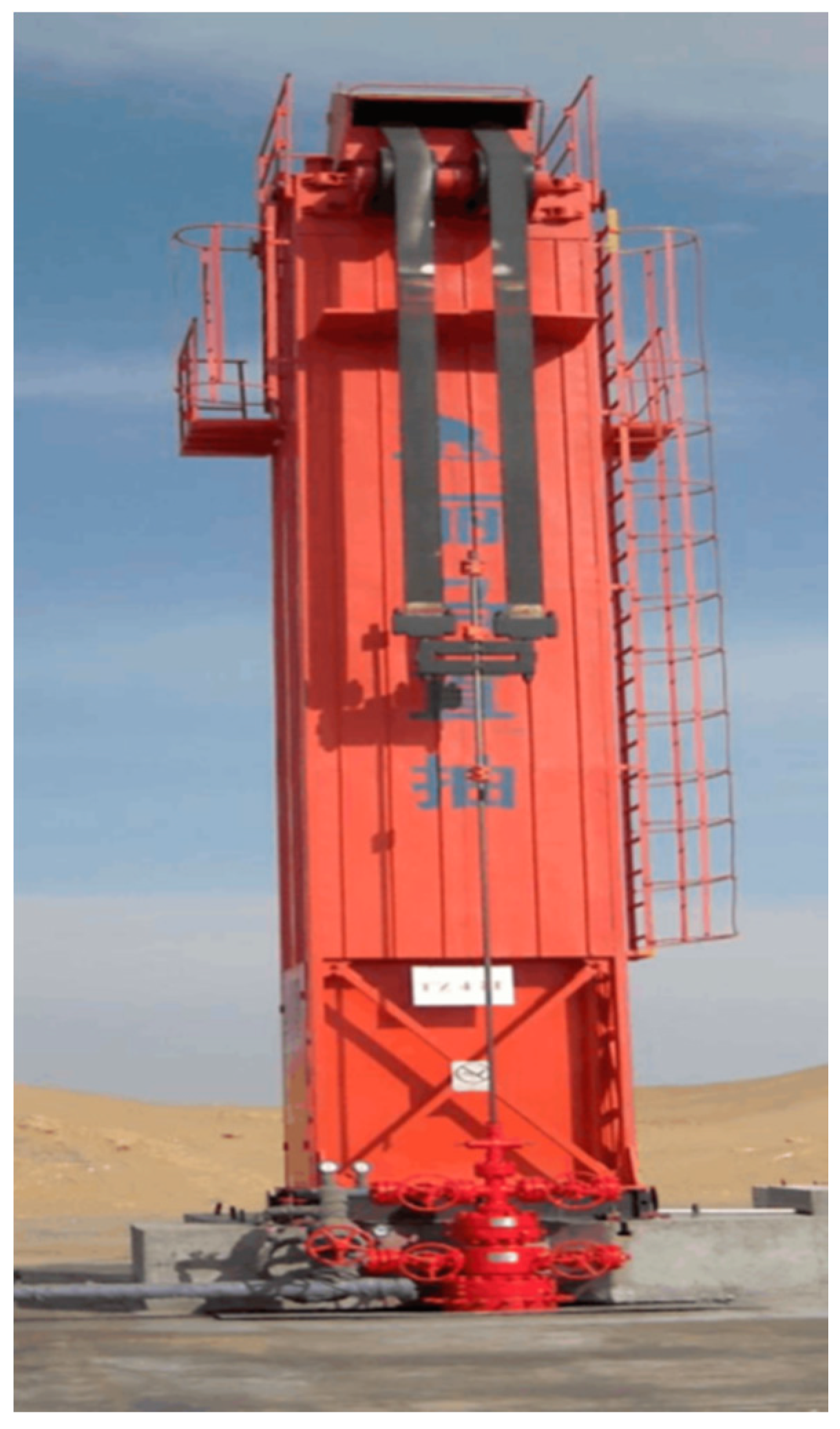
Correspondingly, the compound permanent magnet motor and the linear motor reciprocating machines, shown in Figure 3 and Figure 4, are all drainage machines of the motor reversing type. Compared with the conventional form, by omitting the reducer and the complex reversing system the compound permanent magnet motor drainage machine has a simpler structure and smaller footprint. With the combination of frequency conversion control technology and compound permanent magnet motor, the end balance weight method is adopted, which makes the pumping unit have good energy saving effect. By using control knob control the starting and stopping state and the running speed of the motor, we can adjust the stroke and frequency. Cui [12] and Zhang [13] have stated that this type has relatively high cost, the poor resistance to earthquakes performance and the torque is constrainted by the strength of the permanent magnet, etc. Zhao [14] and Ma [15] also think that the linear motor reciprocating drainage machine has the problem of high cost and difficult maintenance.
In order to obtain the variable transmission ratio movement, the non-circular gear concept arose at a historic moment. Dunkerley has provided a basic exposition of the design and application of elliptical gears in his book [16]. In the 1940s, a group of scholars in Japan represented by Yamazaki and Ota set off a new upsurge in the study of non-circular gears [17], which has formed a relatively perfect theoretical system about non-circlar gears. Marius [18] and Bair [19] and others have used computer software simulation and numerical control machine tool technology to process any-curve non-circular gears. When Bijlsma [20] studied the gravity balance device putting forward the gear train design and parameter calculation method of non-circular gears, these were used to change the reciprocating motion into a continuous pendulum motion. Hebbale [21] used a non-circular gear set to realize stepless speed regulation, thus improving the efficiency of automobile fuel pumps. Doric [22] introduced non-circular gears in the variable movement of internal combustion engines, providing variable compression ratio, variable displacement and combustion at constant volume, greatly improving the advantages of piston mechanisms. Okada [23] in a study of jumping robots, in order to change the speed ratio, designed non-circular gears to change the gear ratio, resulting in high torque and high speed characteristics. Putting energy saving as a starting point in CBM exploitation, to solve the problem of reciprocating motion for no-beam machines, according to an incomplete non-circular gear as the core mechanism of the non-switching type reversing device proposed by Marius [18], this paper designs a kind of incomplete non-circular gear automatic reversing vertical drainage machine. Owing to the higher work efficiency of the gear mechanism than the crank rocker, stable work, robustness to damage and low cost, the utility model has practical design value.
The rest of the paper is organized as follows: in Section 2, the new structural design and working principle of the automatic reversing machine for non-circular gears are summarized. Through consulting and using relevant data, Section 3 introduces the design of non-circular gear pair. Section 4 gives a brief analysis of the performance of the row mining machine. The kinematic simulation analysis of the incomplete non-circular gear train based on Automatic Dynamic Analysis of Mechanical Systems (ADAMS) is demonstrated in Section 5. Section 6 provides an actual application of our product. Our conclusions are summarized in Section 7.
2. Structure Design and Working Principle of Drainage Machines
2.1. Overall Structure Design of Drainage Machines
As shown in Figure 5, the working mechanism of the drainage machine is as follows. The motor is connected with the cycloid pinwheel reducer by a belt drive linked to the non-circular gear reversing box of the core through a coupling. The two speed transmission for extracting the machine’s stroke is connected between the periodic rotation output shaft and cylinder, which is fixed with two winding belts, hanging on the vertical frame round crown sheave, with a belt connected with the counterweight box and a belt-connected sucker rod. After the motor is started and the power is transmitted to the non-circular gear reversing box, the output shaft drives the cylinder to complete a cycle of positive and reverse rotation through which each input shaft rotates for one circle, and the drainage machine realizes a stroke. When the cylinder is used for winding the belt of the sucker rod, the belt which is connected with the counterweight is released, the sucker rod runs upwards, and the drainage machine is in the upper stroke. When the cylinder releases the belt connecting the sucker rod, the oil pumping rod runs downward, and the drainage machine is in the lower stroke. By changing the size of motor end small pulley and the input speed of the non-circular gear reversing box, a regulation is made changing the cycle time output. By adjusting the two speed transmission between the cylinder and the non-circular gear box, the number of turns of the cylinder is changed as well as the stroke of the discharge machine.
2.2. Transmission Scheme and Working Principle of Incomplete Non-Circle Gear Reversing Box
Under the premise of constant rotation direction the design of the non-circular gear reversing box aims to realize the up and down movement of the sucker rod through outputting an automatic reversing circular motion and then driving the cylinder. The movement of the suspension point in a circulation cycle is generally as follows: starting downward from the upper limit, the suspension point accelerates to a certain extent, and then maintains a rapid uniform motion. When near the limit position the suspension point begins to decrease. When the non-circular gear box changes the output rotation direction, starting to accelerate rapidly from the lower limit position, the point reaches and maintains a certain position and begins to slow down close to the limit position, so the drainage is completed by the cycle.
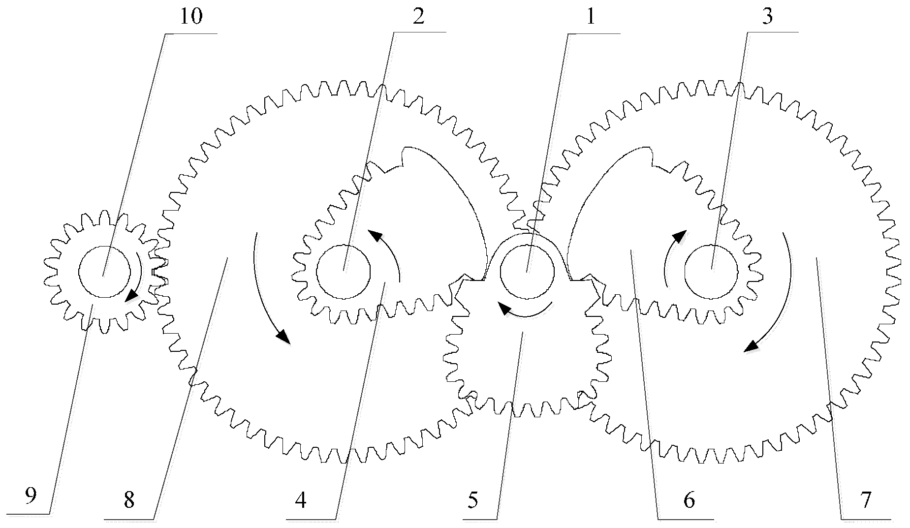
Figure 6 is a structural sketch of the non-circular gear reversing box, and its specific working process is as follows: the power is transmitted to the input shaft 1 by the cycloidal reducer, where the input shaft 1 is designed to rotate clockwise, and the non-circular gear 5 is rotated clockwise. At this time, the non-circular gear 5 is engaged with the part of the non-circular gear 6, and is disengaged from 4. The power is transmitted from the non-circular gear 6 to the non-circular gear 4 by the cylindrical spur gear 7 and the 8, outputting from the cylindrical spur gear 8 through the cylindrical straight gear 9 counterclockwise to the output shaft 10. The input shaft 1 and non-circular gear 5 clockwise rotate 180 degrees, causing the non-circular gear 6 and cylinder gear 7 counterclockwise one time, non-circular gear 4 and spur gear 8 clockwise one time and the output shaft 10 and spur gear 9 counterclockwise one time.
As Figure 7 shows, when the input shaft rotates 180 degrees and continues, the non-circular gear 5 engages with the part of the non-circular gear 4 and is disengaged from the part of the non-circular gear 6. The power is transmitted from the gear 4 to the gear 6 by the coaxial spur gear 8 and the spur gear 7, outputting from the cylindrical spur gear 8 through the cylindrical straight gear 9 clockwise to the output shaft 10. The input shaft 1 and non-circular gear 5 rotate clockwise from 180 degrees to 360, causing the gear 6 and cylinder gear 7 to rotate clockwise one time, non-circular gear 4 and spur gear 8 counterclockwise one time and the output shaft 10 and spur gear 9 clockwise one time. In this process, in addition to the input shaft 1 and the non-circular gear 5, the motion direction, time and angle of the other components are just the opposite of the first 180 degrees.
In a cycle of the input shaft to rotate 360 degrees the input shaft 1 and a non-circular gear 5 clockwise rotate at a fixed speed. The output shaft 10 and gear 9 in the first half cycle are in a non- uniform motion counterclockwise rotation and second half by clockwise. The output movement embodied on the cylinder of the drainage machine is basically that in a stroke the cylinder rotates counterclockwise first and then clockwise.
3. The Design of Non-Circular Gear Pair
3.1. Transmission Principle of Non-Circular Gear Pair
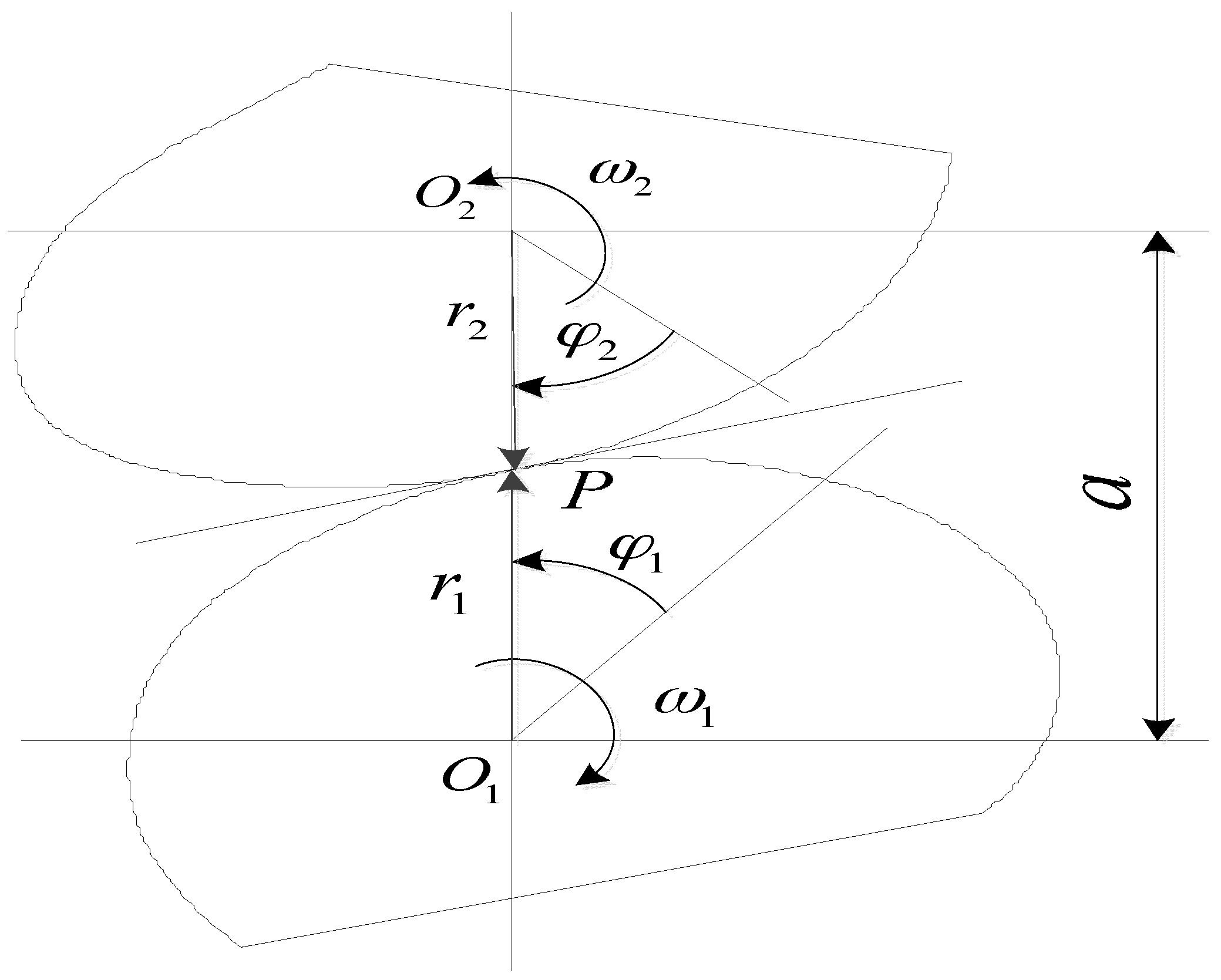
Figure 8 is a diagram of the pitch curve of a pair of non-circular gear with variable transmission ratio and outer engagement, taking the gear 1 as the driving wheel and the gear 2 as driven wheel. We set the center distance of the two gears to a, setting the angle of gear 1 as φ1 and the instantaneous angular velocity as ω, setting the gear 2 angle as φ2 and corresponding to the instantaneous angular velocity ω2. At the initial moment, φ1 = 0, φ2 = 0, the angular velocity ω1 is described by ω1 = dφ1/dt and angular velocity ω2 = dφ2/dt. When gear 1 is engaged with gear 2, there is a certain rotation function relation:
In the variable transmission ratio and external meshing non-circular gear drive, the transmission ratio function is described by:
In the range of φ1, this is a finite and the positive smooth function. According to Equations (1)–(3), the angle function φ2 of gear 2 can be obtained by:
From Figure 8, when two non-circular gears transmit at any moment, there is a point P relative velocity equal to zero, which is a node of gear transmission and also instantaneous velocity center.
When the point P is at the line of centers, the relative speed of two gears is zero, , and the instantaneous transmission ratio is available from:
When the two gear center distance a is constant, the transmission ratio is variable making the corresponding r1, r2 to be variable, that the instantaneous center P position is not fixed. At this time, the trajectory of instantaneous center P is a non-circular curve, which is the instantaneous line of two gears, called non-circular gear pitch curve.
In combination with the above analysis, the equations of the pitch curves of non-circular gear pairs are summarized in the form of polar coordinates. According to Equation (5), the polar equation of the pitch curve of gear 1 can be obtained by:
According to Equations (2) and (5), the curve equation of gear 2 can be obtained by:
With respect to the gear 1 and gear 2 described above, the measuring direction of φ1 and φ2 is opposite to the corresponding rotation angle ω1 and ω2. Therefore, when the center distance of a pair of non-circular gear pairs is determined, the pitch curve of the driving wheel 1 can be obtained by only knowing the transmission ratio function, and then the pitch curve of the driven wheel is obtained by Equation (7) [24,25].
3.2. Design of the Non-Circular Gear Pair
The purpose of designing a non-circular gear drive is that the suspension around at the dead center has slower movement speed and stable commutation, running rapidly in the middle section of the stroke to improve working efficiency. Because of the changing speed of the stroke, each section of the non-circular gear pair can be allocated as follows. For driving non circular gear 5, as shown in Figure 9, taking center O1 as the origin of polar coordinates the curvature radius of the pitch curve varies counterclockwise increasing gradually in the Section 1 of 60 degrees before transmission, unchanged in Section 2 of 60~120 degrees, decreased in the Section 1 of 120~180 degrees, and it is unnecessary to calculate it in the Section 3 of 180~360 degrees.
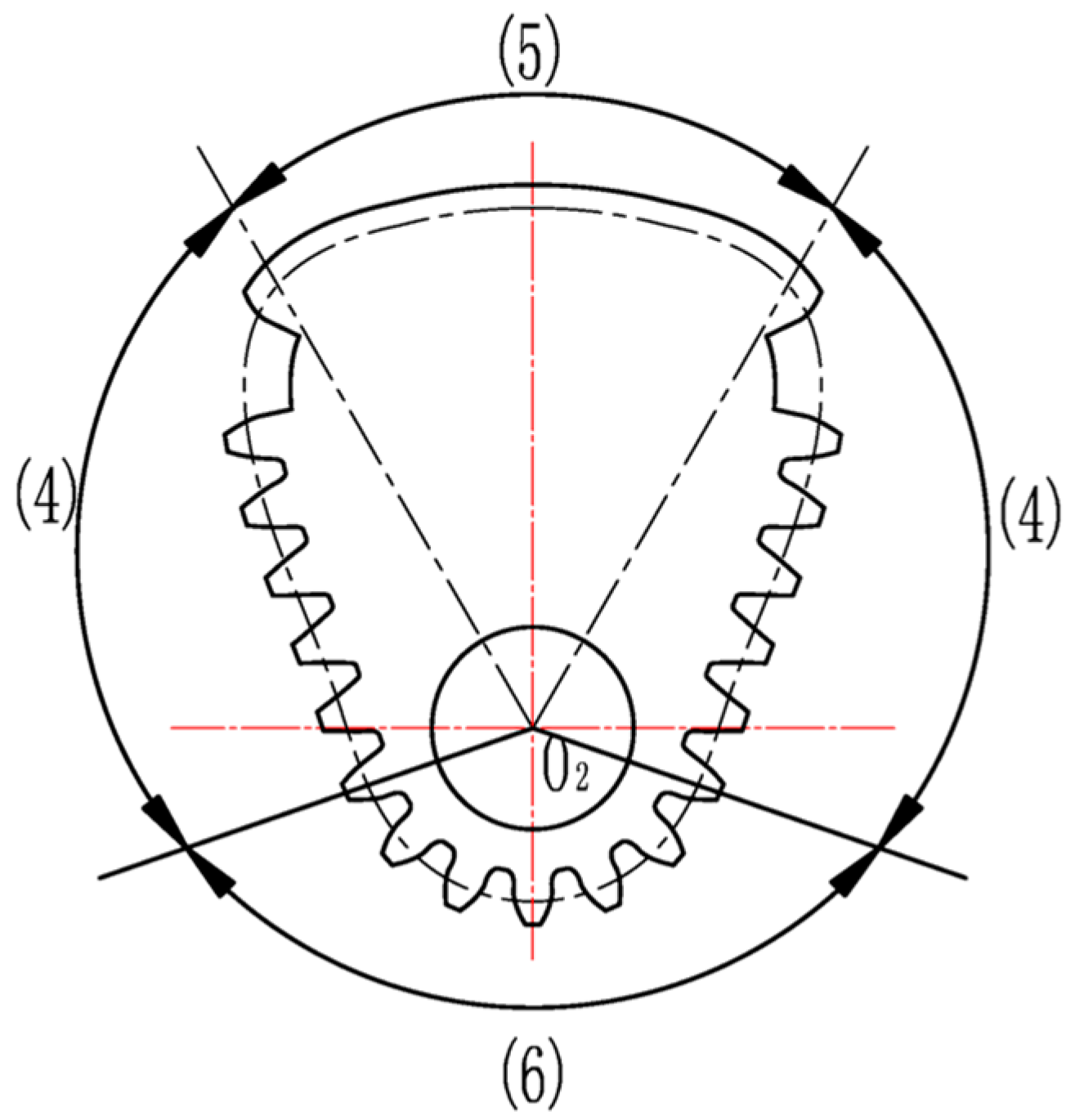
Due to the constant distance of the centers the pitch curve of gear 4, like gear 6 it varies with the distribution of driving non-circular gears. From Figure 10, taking center O2 as the origin of polar coordinates, the radius of curvature varies counterclockwise increased in Section 4, in does not need to be calculated in the no-tooth area 5, decreased again in Section 4, and unchanged in Section 6.
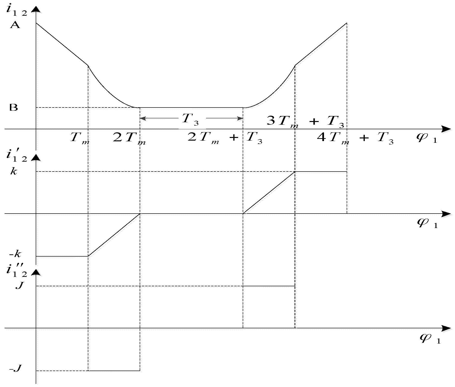
As shown in Figure 11, according to the distribution of the above gear pitch curve and the motion state of the gear pair, the regulation of transmission ratio can be formulated as the angle changing of the driving non-circular gear 5 [26].
In Figure 11, A is the maximum of the gear ratio, and B is the minimum. In the angle allocation of the driving gear, Tm = π/6, T3 = 2Tm, K = (A − B)/2Tm and J = (A − B)/Tm2.
By using the integral relation, the function relation of i12’ with the angle φ1 change of the driving gear can be deduced as:
With the rotation angle change of the driving gear the function can be obtained by integrating as:
Combined with the actual conditions of the non-circular gear reversing box, we should try to get the angle φ2 of the driven non-circular gear 4, 6 toothed part large in order to increase the non-circular gear’s meshing area and reduce the error, generally taking φ2 as 300–330 degrees (300 degrees in this article). The design parameters of the non-circular gear are as follows: center distance of non-circular gear pair a = 360 mm, maximum transmission ratio i12max = 2.811, minimum transmission ratio i12min = 1/3, angle of driven non-circular gear 4, 6 = 300 degrees, so the pitch curve of driving non-circular gear 5 (Figure 12a) and non-circular curve section gears 4, 6 (Figure 12b) are calculated by a MATLAB program [27,28].
3.3. Establishment of the Non-Circular Gear Pitch Curve
In order to machine the gears, it is necessary to fit the incomplete pitch curves to a complete closed non-circular curve. Using the imported non-circular gear pitch curve obtained by programming calculations in MATLAB (R2011b, MathWorks, Natick, MA, USA), Computer Aided X Alliance (CAXA) put the two rotation centers of the non-circular gear as the center of a circle, taking a circle of 90 mm radius to fit the driving toothless non-circular gear and a circle of 270 mm radius for the driven one.
For the transition region of an active non-circular gear, we take the tangent of the circle of 90 mm radius at the end point of the effective section curve. For the transition region of the driven non-circular gear, the middle section of the intersection of the tangent line at the end point of the effective curve and circle for 270 mm radius are taken. The final fit figure is shown in Figure 13.
In the design of this paper, the modulus m of non-circular gear is 12, the tooth width b is 250 mm, the largest outer diameter R is 270 mm, the addendum coefficient is 1, and the clearance coefficient c* is 0.25. In this paper, the gear profile of non-circular gear is designed by means of a generating gear (pinion cutter), which is a method of meshing between involute cylindrical spur gears and non-circular gears. Finally, we use CAXA to create the non-circular gear profile, as shown in Figure 14.
3.4. Design of Non-Circular Gear Reversing Box
With every turn of the input shaft of the non-circular gear reversing box, the drainage machine completes a row extraction action, and that means it’s done a run. Regardless of the magnitude of the reverse stroke, the non-circular gear reversing box always has this characteristic. The stroke size of the drainage machine directly reflects the rotation number of the roller, and it is related to the effective working radius of the roller. The number of turns of the roller is determined by the non-circular gear reversing box and the second gear transmission between the roller and the non-circular gear reversing box. In order to simplify the structure of the second gear transmission and reduce the energy losses during transmission, the output shaft of the non-circular gear reversing box can be directly connected with the roller by using one of the gears in the transmission, and the transmission ratio between the non-circular gear reversing box output shaft and the roller is one.
In the case where the non-circular gear reversing box output shaft is directly connected to the roller, this paper designs the structure of non-circular gear reversing box. In the processing of deduction, unit of angular velocity is defined as revolutions per second. When the stroke value of drainage machine polished rod is the maximum, it satisfies Smax = 2.5 m, and roller diameter satisfies d = 300 mm. In a stroke, the speed of output shaft 10 is the same as that of the cylindrical spur gears 9 which is on output shaft 10 (see Figure 6):
The speed of the cylindrical gear 8 in engagement with the standard cylindrical spur gear 9 is the same as that of driven non-circular gears 4 and 6. In a stroke, driven non-circular gears 4 and 6 rotate 300 degrees, the average speed of the standard cylindrical spur gear 8 is:
When the stroke value is the maximum, it satisfies Smax = 2.5 m, the actual transmission ratio i89 between standard cylindrical spur gears 8 and 9 will satisfy:
When the number of teeth of the pinion 9 satisfies Z9 = 18, and large gears 8 and 7 satisfy Z8 = Z8 = 60, actual transmission ratio will satisfy:
When the modulus satisfies m = 12, We can get Smax = 2.6 m, diameter of the large cylindrical spur gears 8 and 7 are 720 mm, and the diameter of the small cylindrical spur gear 9 is 216 mm.
4. Efficiency Analysis of the New Drainage Machine and the Old
The non-circular gear automatic reversing vertical drainage machine designed in this paper abandons the four-bar linkage of beam pumping units, so there will be some improvement in the work efficiency, and we will discuss the problem of the efficiency.
Generally, we regard the polished rod eye of the drainage machine as the dividing line, the efficiency above it is called the ground efficiency, and the efficiency under it is called downhole efficiency. This paper studies the use of non-circular gear automatic reversing vertical drainage machine instead of beam pumping unit, so only the ground efficiency is simply analyzed. Because of the continuous change of the polished rod load when the drainage machine is working, its instantaneous input and output power also changes in real time, so the average working efficiency of each cycle is analyzed in order to facilitate the calculations.
(1) The ground efficiency of beam pumping unit
The ground efficiency of the traditional three pumping equipment is mainly affected by the efficiency of the transmission parts, like the motor, belt drive, reducer and four-link linkage, so the ground efficiency formula is calculated as:
In the formula above, η1—motor working efficiency; η2—belt pulley working efficiency; η3—reducer transmission efficiency; η4—four-bar linkage transmission efficiency.
Motor working efficiency: the efficiency of the motor nameplate is generally data at a load rate greater than 60%, and its maximum value is not more than 0.95, but when the beam pumping unit is working, the load is always changing and the power factor of the motor is low, so the efficiency η1 of the motor is only 0.8 at most.
Belt pulley working efficiency: referring to the mechanical design manual, the belt transmission efficiency is 0.96, which is efficiency independent of load. Considering the actual working condition, the belt pulley transmission efficiency of the drainage machine is between 0.85 and 0.90, and the highest efficiency is 0.90.
Reducer transmission efficiency: refer to the mechanical design manual, the gear transmission efficiency is 0.98, with a total of three pairs; bearing transmission efficiency of 0.99, with a total of three pairs; the calculated η3 is 0.91.
Four-bar linkage transmission efficiency: the energy of the four-bar linkage of the pumping unit is mainly lost at the bearing and the wire rope and the burner, the bearing transmission efficiency is 0.99, with a total of three pairs. The transmission efficiency η4 of the four-bar linkage is 0.95 when the efficiency of the wire rope is 0.98. Based on the above analysis, the ground efficiency of beam pumping unit can reach the maximum:
(2) Ground efficiency analysis of non-circular gear automatic reversing vertical drainage machine
The electric efficiency of : Non-circular gear automatic reversing vertical drainage machine designed in this paper cancels the switching mode type four-bar linkage, it uses the non-circular gear reversing box for reversing, and adopts a balance system similar to a seesaw. In the course of work, the load on the roller varies little and motor of the roller can still work when its load rate is greater than 60%, the polished rod is in rapid motion in most strokes, and it can remain uniform, too. Therefore, this motor is relatively stable at work and has high efficiency, which can reach = 0.95.
The transmission efficiency of : The non-circular gear automatic reversing vertical drainage machine is mainly powered by gears and pulleys, similarly, pulley efficiency is 0.9.
The transmission efficiency of : Referring to the mechanical design manual, the efficiency of the cycloid pin gear reducer is 0.96, and the transmission efficiency of the gear transmission in the two shift gear is 0.98, with a total of two pairs. The transmission efficiency of the bearing is 0.99, with a total of three pairs, and the efficiency is 0.89.
The transmission efficiency of : The four link mechanism was cancelled, two pulley groups were added, the efficiency was 0.99, the belt efficiency was 0.98, and the total efficiency was 0.96.
Through the above analysis we can see that the ground efficiency of non-circular gear automatic reversing vertical drainage machine is up to:
It can be seen that when calculating the two kinds of row production equipment with the maximum target value, the efficiency of the new type of drainage machine is 11% higher than that of the conventional beam pumping unit and the positive effect is obvious.
5. Kinematics Analysis Based on ADAMS
5.1. Kinematics Simulation Analysis of the Gear System at Incomplete Non-Circular Gear Reversing Box
The inside of the non-circular gear box is mainly composed of a driving non-circular gear, two driven non-circular gears, two large cylindrical straight gears which are coaxial with two driven non-circular gears and a small cylindrical spur gear. The main parameters of each gear at non-circular gear box are shown in Table 1:
Importing the gear system at non-circular gear reversing box into ADAMS, according to the kinematic relationship, this paper adds the necessary kinematic pairs on the gear system at incomplete non-circular gear reversing box. In order to verify the correctness of the design, the contact force is defined in the gear mesh, and 0.1 is used as the input shaft speed. After the parameters are set up, the simulation is performed, the input shaft of non-circular gear reversing box rotates a circle, and the output shaft rotates in reverse direction, this is a movement cycle, the time is 10 seconds. Therefore, in the simulation interface, the simulation time is set to 20 s, and the step size is set to 0.01, the video screenshot is shown in Figure 15.
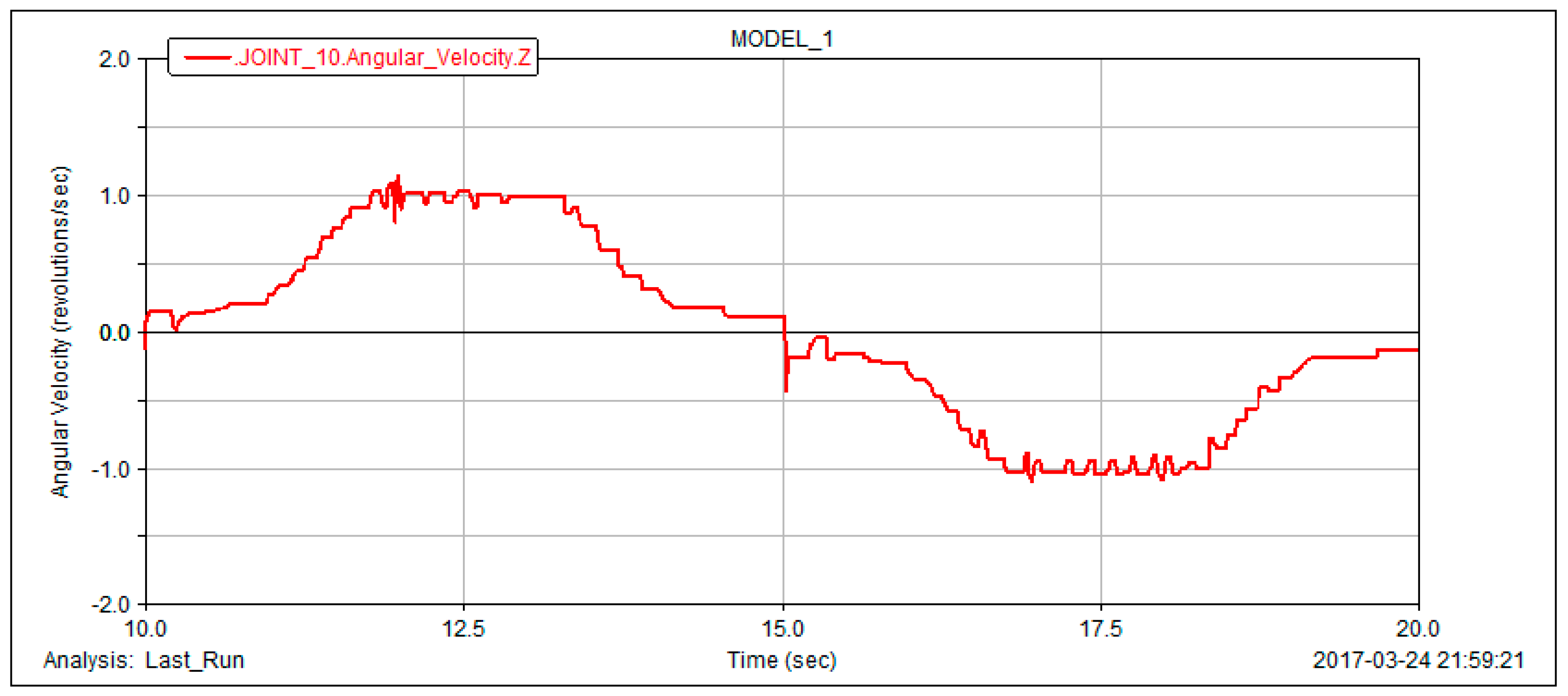
In post-processing, the rotational speed of the output shaft is obtained. We remove the unsteady state of the non-circular gear reversing box when it is just started, take the simulation curve of the output shaft speed of the non-circular gear reversing box when it is working smoothly at 10 s~20 s (as shown in Figure 16).
The simulation curve of ten seconds shows the output shaft speed of the non-circular gear reversing box at the drainage machine in one stroke, It can be seen that the driven non-circular gear accelerates very rapidly in the first sixth of the time, maintains a fast and constant motion in the middle sixth of the time, and decelerates very rapidly in the last sixth of the time. It can be concluded that in terms of the movement characteristics, the simulation results are completely in accordance with the design requirements. Although the output shaft speed changes are consistent with the motion requirements of the polished rod, some burrs are present in the simulation curve.
Visibly, there is a certain deviation between the gear profile of non-circular gear designed by means of generating gear (pinion cutter) which is a method of meshing between involute cylindrical spur gears and non-circular gears and ideal value, especially the place where the non-circular gear pair is just beginning to engage. That means when the largest gear teeth of the active non-circular gear are meshed with the driven non-circular gear, the burr of the simulation curve is more prominent.
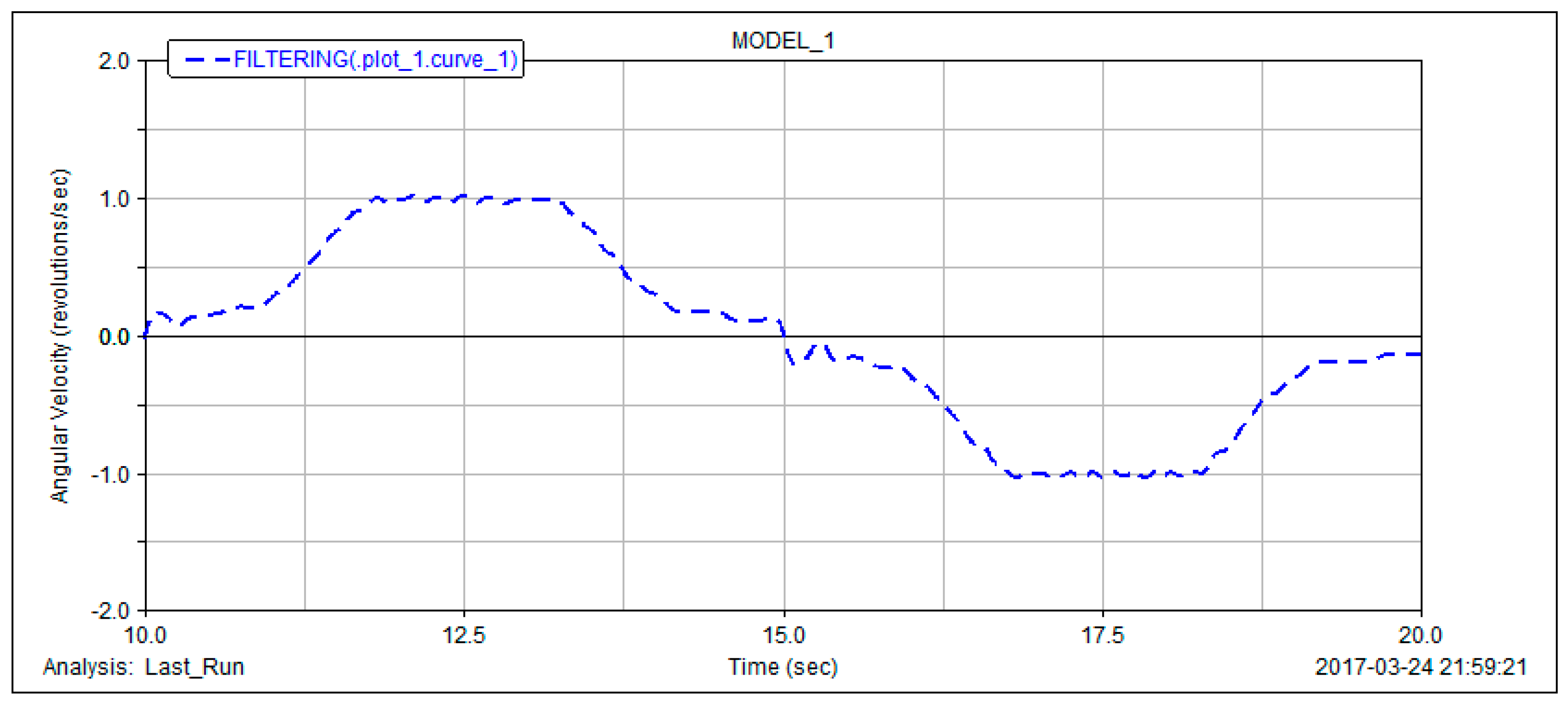
Considering that the ordinate itself is very small, the burr jump is actually not large, after using the ADAMS digital filter of Butterworth to filter out the high frequency signal of dash jump, it is shown in Figure 17.
As shown in Figure 18, the filtered curve is basically the same as the theoretical value of the output shaft speed of the non-circular gear reversing box. Figure 18 is a theoretical calculation taking into account the output shaft speed in one stroke. As the non-circular gear reversing box has an impact during commutation, there will be a relatively large jump in speed variation at fifteenth seconds. As the low speed of the commutation, the jump value is not large.
5.2. Movement Analysis of Drainage Machine Polished Rod Displacement
The kinematic simulation results of the non-circular gear reversing box output shaft are compared with the theoretical calculation values, and the correctness of the design is verified. The output shaft speed simulation curve is processed by scaling and integral commands of the curve editing in the ADAMS postprocessor to validate whether the stroke of this whole drainage machine meets the design requirements. Equaling to the effective line speed of roller outer diameter, the polished rod speed of the drainage machine is:
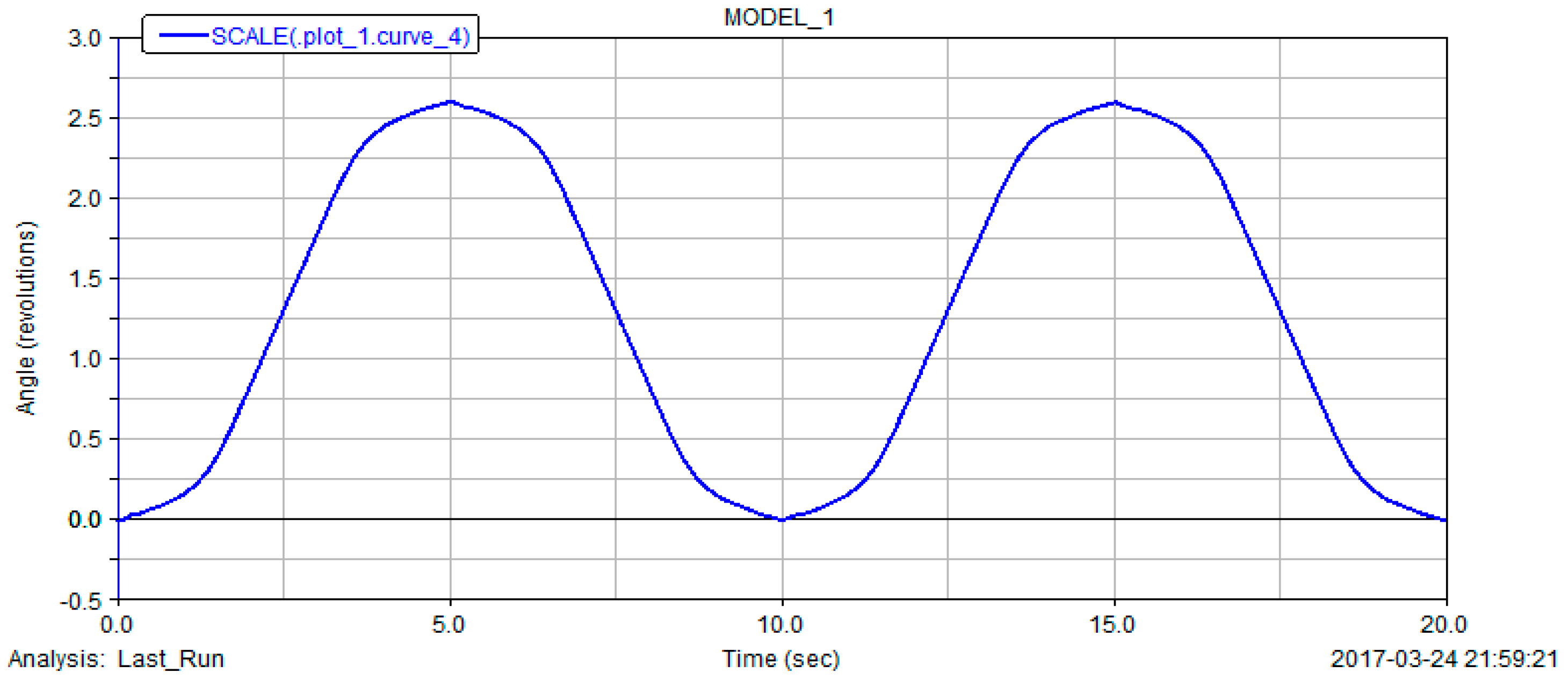
Consequently, the simulation curve of the output shaft speed of the non-circular gear reversing box is enlarged by 0.3π times by the scaling command, and the effective output line speed of the roller, namely the polished rod speed, is obtained. Then the integral of the scaled curve is processed, and the curve of drainage machine polished rod displacement over time will be obtained, as shown in Figure 19.
It can be seen that the polished rod takes 10 s as a periodic motion, and the maximum stroke is about 2.6 m, that is to say, the drainage machine is 6 times /min, and the stroke is 2.6 m, which fully meets the design requirements. In addition, there is a quite small sharp point at the crest of the curve so that the curve does not change smoothly. The cause of this phenomenon is that the polished rod is not accelerating from rest when it's moving up and down, but it has a small reverse velocity. Therefore, in the stroke curve, the slope of the wave peak and trough attachment is not 0, and there is a small cusp.
6. Industrial Application
The new pump in this paper compared with beam pumping oil machine has the following main system differences: a new type of transmission mechanism, converting rotational motion into reciprocating, is designed to replace the four link mechanism of a beam pumping unit. Then according to the change of the adaptability of the core institutions, adjustable stroke mechanism and balancing device are designed and the new pump system diagram is shown in Figure 20. This pump is changed to drum type pump with vertical frame from the conventional by the design of reversing transmission device, mainly composed of a motor, adjusting the stroke mechanism, speed reducer, reversing device, roller, and counterweight parts. Figure 21 is a non-circular gear reversing box device photo, and Figure 22 is a field test photo of a coal seam gas extraction machine based on incomplete non-circular gears.
7. Conclusions
Based on the characteristics of polished rod movement at the coalbed methane drainage machine, this paper designed a non-circular gear reversing box which conformed to its movement requirements, simulated it by dynamic software ADAMS, and compared the simulation value with the theoretical calculation value. The design method of this machine is not only suitable for coalbed methane wells, but also for oil field pumping units, as the non-circular gear automatic reversing vertical drainage machine can also be used for oil production. This article mainly draws the following conclusions:
- (1)
- According to the characteristics of the inconvenient adjustment and low efficiency of the working parameters of the beam pumping unit, a new type of drainage machine is proposed to replace the conventional girder with the non-circular gear as the core for coalbed methane well pumping devices.
- (2)
- Through the transmission principle of the incomplete non-circular gear reversing box, a detailed design calculation of the incomplete non-circular gear is carried out, the non-uniform motion of non-circular gear pair is adopted to realize the variable speed movement in the stroke of the drainage machine, and the automatic reversing is realized by cooperating with other cylindrical gears in the gearbox, then the model of the incomplete non-circular gear and reversing gear system is established.
- (3)
- The paper analyzed the working performance of the drainage machine, and completed the theoretical calculation of the polished rod speed and acceleration; the efficiency of the new type of drainage machine and the conventional beam pumping unit is compared and analyzed simply, and the results show that the efficiency of the new type of drainage machine is about 11% higher than that of the traditional walking beam type pumping unit.
- (4)
- Whether the meshing process of one pair of non-circular gear pairs reaches the theoretical calculation value is verified by ADAMS; then the whole non-circular gear reversing gear train is simulated by ADAMS, and the output shaft speed and the simulation curve of the polished rod displacement are obtained. Based on the comparison with the theoretical values, the accuracy of the design is verified.
Acknowledgments
The authors are grateful to the anonymous referees for their valuable comments and suggestions for improving the presentation of this paper. Project funded by the Priority Academic Program Development of Jiangsu Higher Education Institutions (PAPD). Production, Prospective Joint Research Projects in Jiangsu Province (BY2016026-02).
Author Contributions
Guiyun Xu and Weijun Dai contributed the new design and simulation; Guiyun Xu and Xiaoguang Zhang designed the test device; Guiyun Xu, Weijun Dai and Dezheng Hua completed the process of model machine; Dezheng Hua wrote the paper.
Conflicts of Interest
The authors declare no conflict of interest.
References
- Tang, Y. Coalbed Methane Resources and Prospects in China; Academic Year of the Chinese Geological Society: Beijing, China, 2013. [Google Scholar]
- Feng, C.B. Synthetic description of status and energy-saving method on oil-abstracting engines in oilfield. Inn. Mong. Petrochem. Ind. 2008, 34, 31–33. [Google Scholar]
- Li, D.; Fan, J.; Wang, L.; Kou, C. Curved beam pumping unit. Oil Forum 2013, 32, 63–65. [Google Scholar]
- Fu, H.; Zou, L.; Wang, Y.; Feng, Z.; Song, Z. Study on design and simulation analysis of the double horse-head pumping unit based on the compound balance structure. Proc. Inst. Mech. Eng. Part C 2015, 229, 3034–3046. [Google Scholar] [CrossRef]
- Liu, C. Energy-saving improvement for convention oil pumping unit of oilfield. Energy Conserv. Petroleum Petrochem. Ind. 2011, 1, 25–27. [Google Scholar]
- Fan, W.M.; Song, J.C. Design of a new energy-saving driving system for oil pumping unit. Mach. Des. Manuf. 2014, 7, 68–71. [Google Scholar]
- Li, Q.; Deng, Z.; Chen, H.; Peng, X. No beam pumping unit’s dynamic analysis. J. Liaoning Shihua Univ. 2014, 34, 50–54. [Google Scholar]
- Liu, J.; Cui, J.; Xiao, W.; Fu, D.; Yang, L.; Li, L. Design of mechanical reversing device without switching for pumping unit. Oil Field Equip. 2015, 44, 26–29. [Google Scholar]
- Qi, Y.-G.; Chen, J. Dynamics analysis of electrical machinery commutation for intelligent pumping unit. Oil Field Equip. 2008, 37, 62–65. [Google Scholar]
- Niu, S.G.; Zhao, Y.H. The research of chain type hydraulic pumping unit of long stroke. Mach. Tool Hydraul. 2005, 8, 87–88. [Google Scholar]
- Shao, Z.M.; Niu, S.G. The study of long stroke pumping unit with hydraulic-chain drive. Oil Field Equip. 2005, 4, 14–16. [Google Scholar]
- Cui, J.; Xiao, W.; Feng, H.; Dong, W.; Zhang, Y.; Wang, Z. Long stroke pumping unit driven by low-speed permanent magnet synchronous motor. Soc. Petroleum Eng. 2014. [Google Scholar] [CrossRef]
- Zhang, Z.; He, L. PMSM control simulation based on pumping unit. TELKOMNIKA Indones. J. Electr. Eng. 2014, 36, 108–111. [Google Scholar] [CrossRef]
- Zhao, Y.; Yan, H.; Wang, S.; Zhao, D.; Liu, D.; Xu, H.; Yang, X. Research on multi-section effective linear motor pumping unit. In Proceedings of the IEEE International Conference on Mechatronics and Automation, Harbin, China, 7–10 August 2016; pp. 1855–1859. [Google Scholar]
- Ma, W.Z.; Zhang, H.M.; Sun, J.Y.; Tian, D.B.; Pang, H.F. Research on the design of linear drive motor of new pumping unit. Adv. Mater. Res. 2012, 433–440, 5025–5031. [Google Scholar] [CrossRef]
- Dunkerley, K.J. Mechanism; Longmans Green and Co Publisher: London, UK, 1910. [Google Scholar]
- Ma, Y. Gear Design of Variable Drive Ratio Limited Slip Differential. Ph.D. Thesis, Wuhan University of Technology, Wuhan, China, 2007. [Google Scholar]
- Marius, V.; Laurentia, A.; Ana, C. A brief synthesis of noncircular gears. Constanta Marit. Univ. Ann. 2011, 16, 191–196. [Google Scholar]
- Bair, B.W. Computerized tooth profile generation of elliptical gears manufactured by shaper cutters. J. Mater. Process. Technol. 2002, 122, 139–147. [Google Scholar] [CrossRef]
- Bijlsma, B.G.; Radaelli, G.; Herder, J.L. Design of a compact gravity equilibrator with an unlimited range of motion. In Proceedings of the ASME International Design Engineering Technical Conferences and Computers and Information in Engineering Conference (IDETC/CIE), Charlotte, NC, USA, 21–24 August 2016. [Google Scholar]
- Hebbale, K.; Li, D.; Zhou, J. Study of a non-circular gear infinitely variable transmission. In Proceedings of the ASME 7th Annual Dynamic Systems and Control Conference Research Workshop Israel Science Foundation on Infinite Products of Operators and their Applications, San Antonio, TX, USA, 22–24 October 2014. [Google Scholar]
- Doric, J.Z.; Klinar, I.J. Efficiency of a new internal combustion engine concept with variable piston motion. Therm. Sci. 2014, 18, 113–127. [Google Scholar] [CrossRef] [Green Version]
- Okada, M.; Takeda, Y. Synthesis and evaluation of non-circular gear that realizes optimal gear ratio for jumping robot. In Proceedings of the IEEE/RSJ International Conference on Intelligent Robots and Systems (IROS), Tokyo, Japan, 3–8 November 2013; pp. 5524–5529. [Google Scholar]
- Litvin, F.L. Noncircular Gears: Design and Generation; Cambridge University Press: Cambridge, UK, 2009. [Google Scholar]
- Litvin, F.L.; Gonzalez-Perez, I.; Fuentes, A.; Kenichi, H. Design and investigation of gear drives with non-circular gears applied for speed variation and generation of functions. Comput. Methods Appl. Mech. Eng. 2008, 197, 3783–3802. [Google Scholar] [CrossRef]
- Sun, K.; Zheng, F.; Chen, D.; Tong, T. The design method and analysis of non-circular gear based on variable ratio function. J. Mech. Transm. 2013, 37, 87–89. [Google Scholar]
- Zhang, J.; Bin, Y.U.; Shui, J.; Qi, X. Design of the pitch curves of non-circular gears based on MATLAB. Mach. Electron. 2016, 34, 17–20. [Google Scholar]
- Lei, L.I.; Chang-Long, D.U.; Yang, S.G. Solving of non-circular planetary gear pitch curve based on MATLAB. Coal Mine Mach. 2008, 29, 23–25. [Google Scholar]
Figure 1.
Conventional beam-pumping unit.
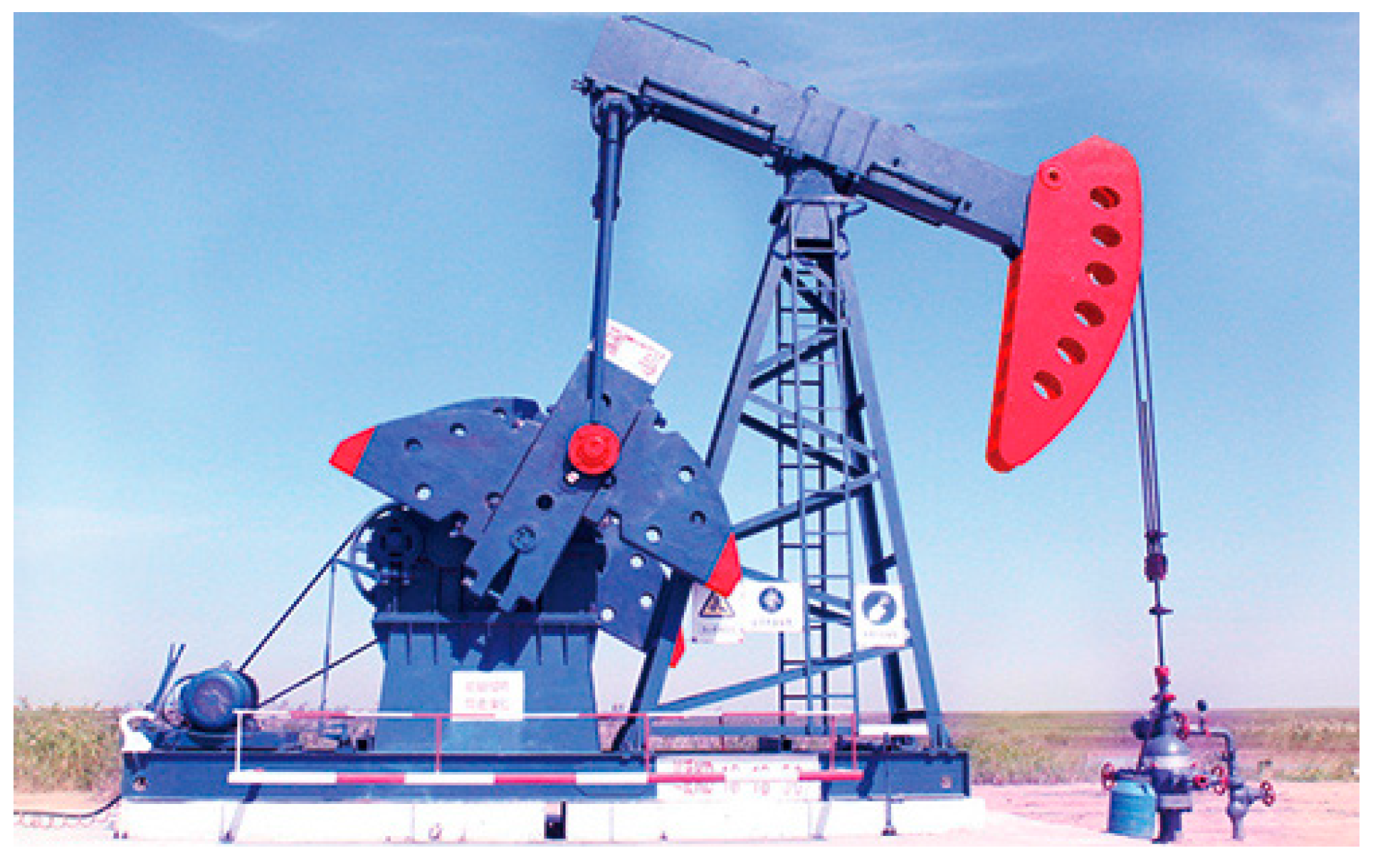
Figure 2.
Chain-type pumping unit.
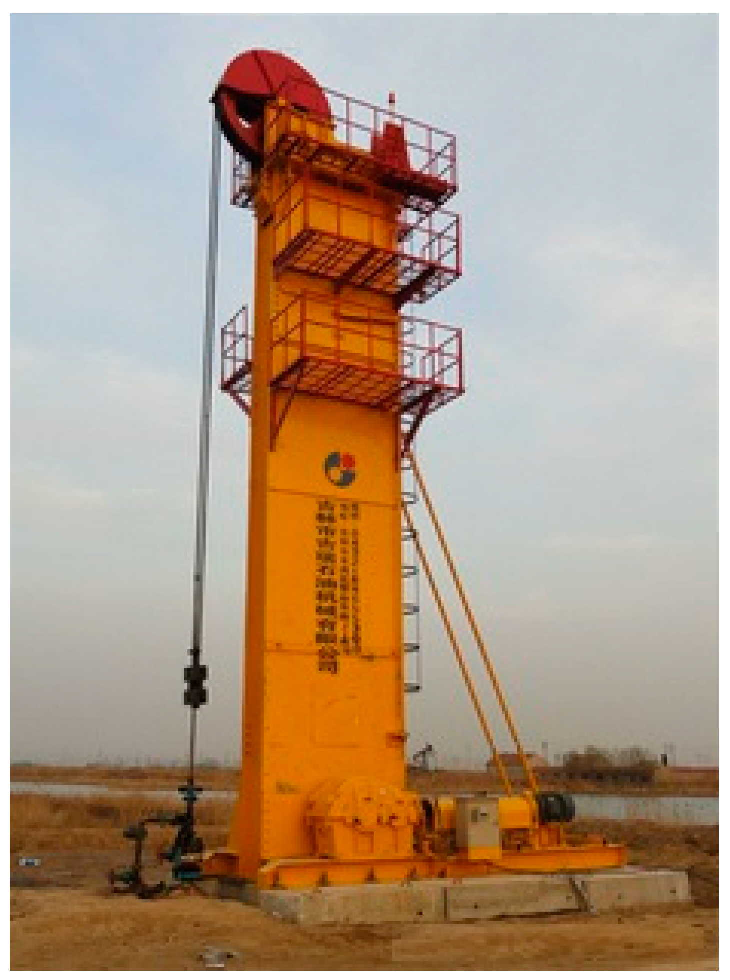
Figure 3.
Compound permanent magnet synchronous motor pumping unit.
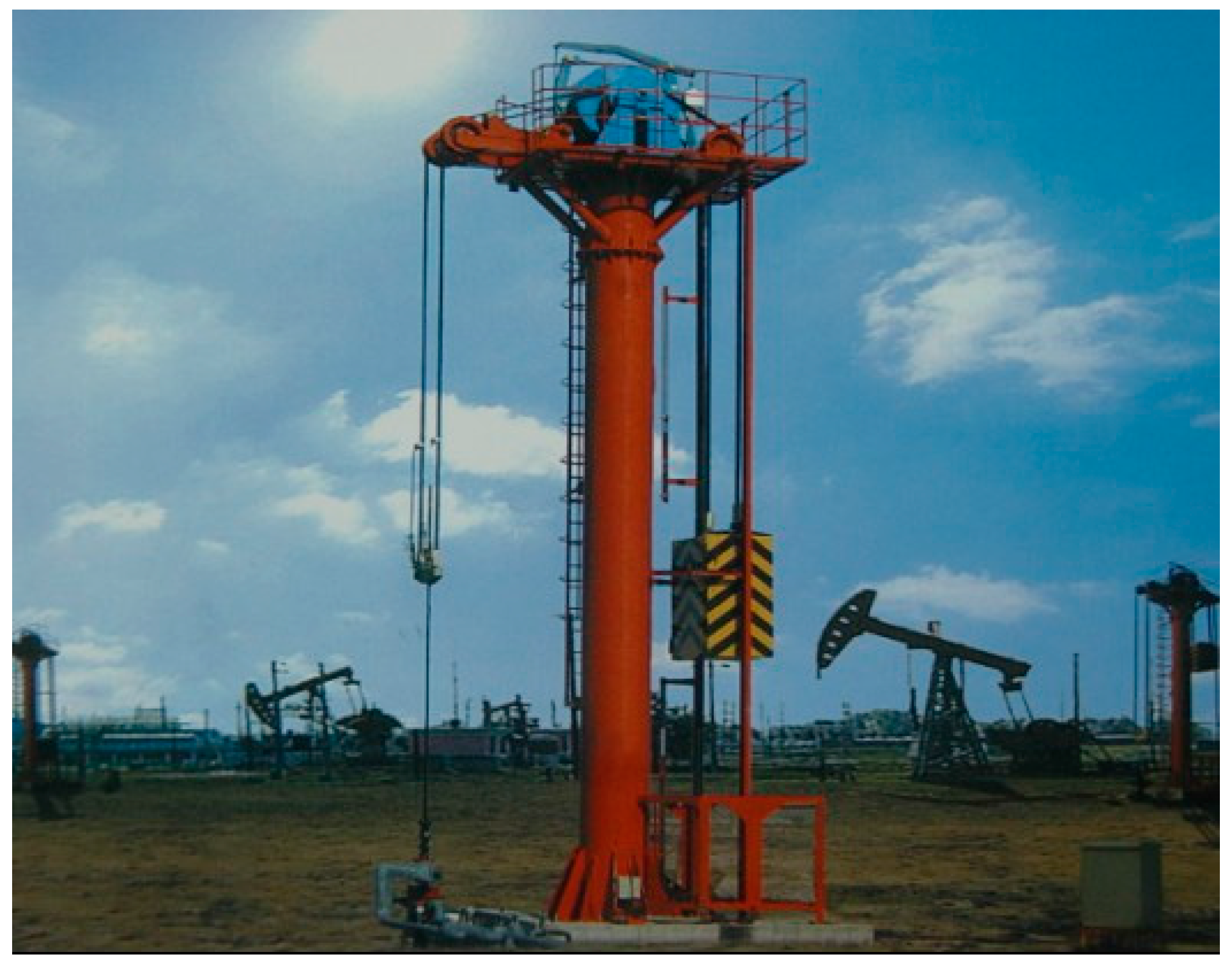
Figure 4.
Linear motor reciprocating pumping unit.

Figure 5.
General structure of an automatic reversing vertical drainage machine for non-circular gears. 1—permanent magnet synchronous motor, 2—small belt pulley, 3—big belt pulley, 4—cycloid pinwheel reducer, 5—non-circular gear reversing box, 6—counterweight, 7—cylinder, 8—stroke reducer, 9—pumping rod, 10—transmission belt, 11—vertical frame, 12—crown sheave.
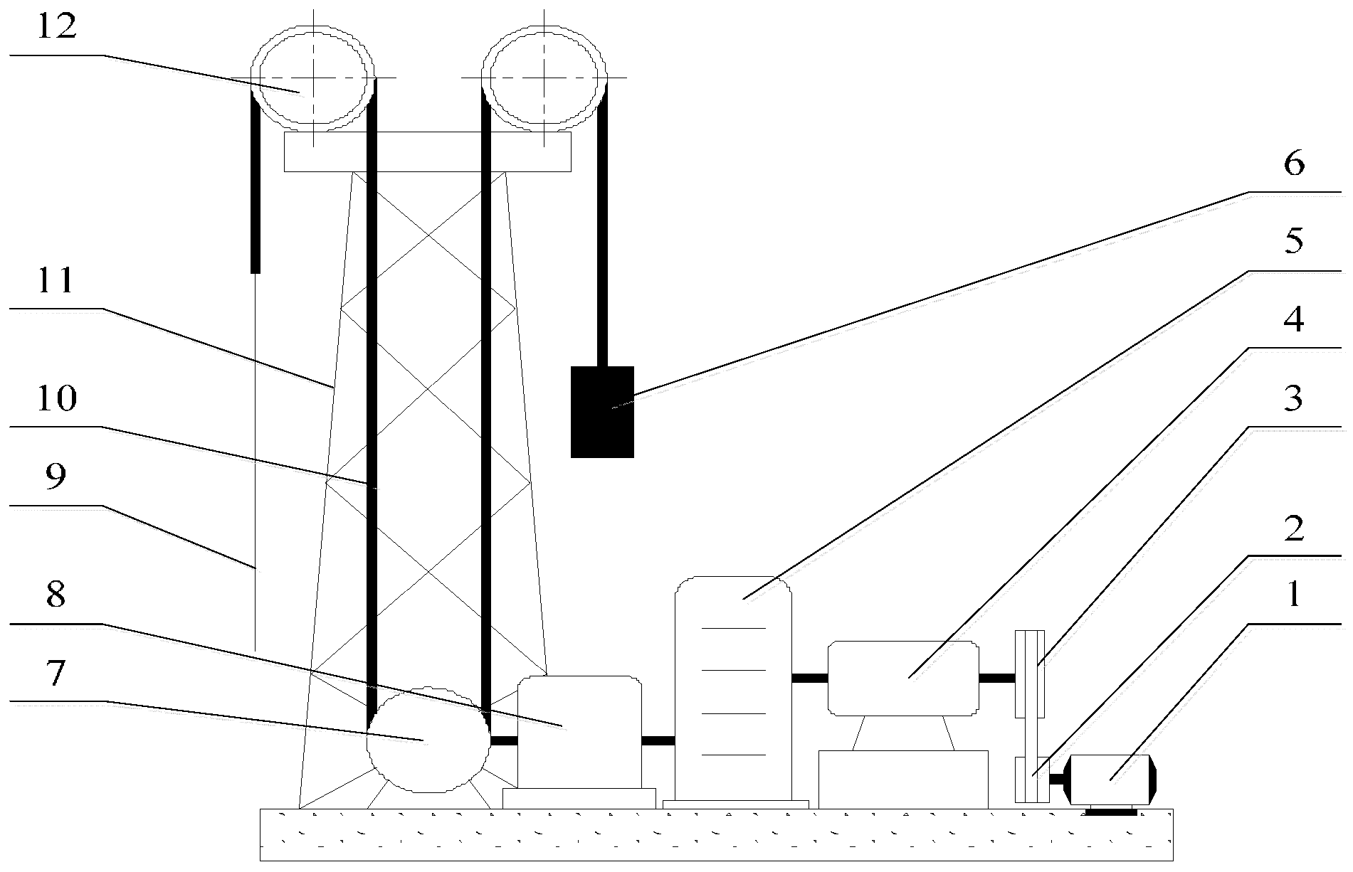
Figure 6.
Sketch of a non-circular gear reversing box. 1—input shaft, 2, 3—transmission shaft, 4, 6—driven non-circular gear, 5—driving non-circular gear, 7, 8, 9—spur gear, 10—output shaft, 11—gear box.
Figure 6.
Sketch of a non-circular gear reversing box. 1—input shaft, 2, 3—transmission shaft, 4, 6—driven non-circular gear, 5—driving non-circular gear, 7, 8, 9—spur gear, 10—output shaft, 11—gear box.
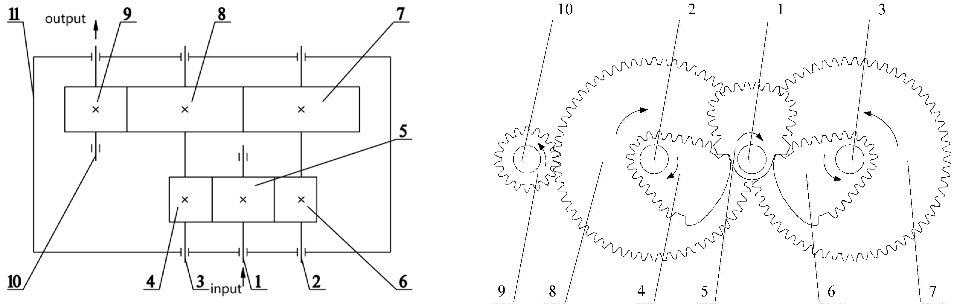
Figure 7.
Engagement condition of the non-circular gears when the input shaft rotates 180 degrees. 1—input shaft, 2, 3—transmission shaft, 4, 6-driven non-circular gear, 5—driving non-circular gear, 7, 8, 9—spur gear, 10—output shaft.
Figure 7.
Engagement condition of the non-circular gears when the input shaft rotates 180 degrees. 1—input shaft, 2, 3—transmission shaft, 4, 6-driven non-circular gear, 5—driving non-circular gear, 7, 8, 9—spur gear, 10—output shaft.

Figure 8.
The pitch curves of a pair of non-circular gears.

Figure 9.
Distribution of the pitch curve of driving gear 5.
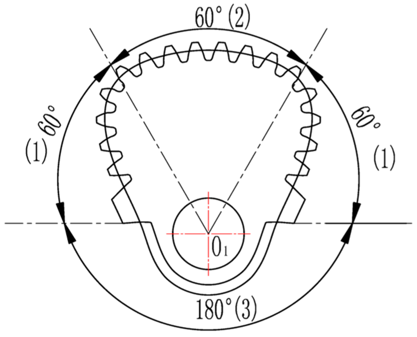
Figure 10.
Distribution of the pitch curve of driven gears 4, 6.

Figure 11.
Curve of drive ratio function.

Figure 12.
The pitch curve of non-circular gears. (a) The pitch curve of gear 5; (b) the pitch curve of gears 4 and 6.
Figure 12.
The pitch curve of non-circular gears. (a) The pitch curve of gear 5; (b) the pitch curve of gears 4 and 6.
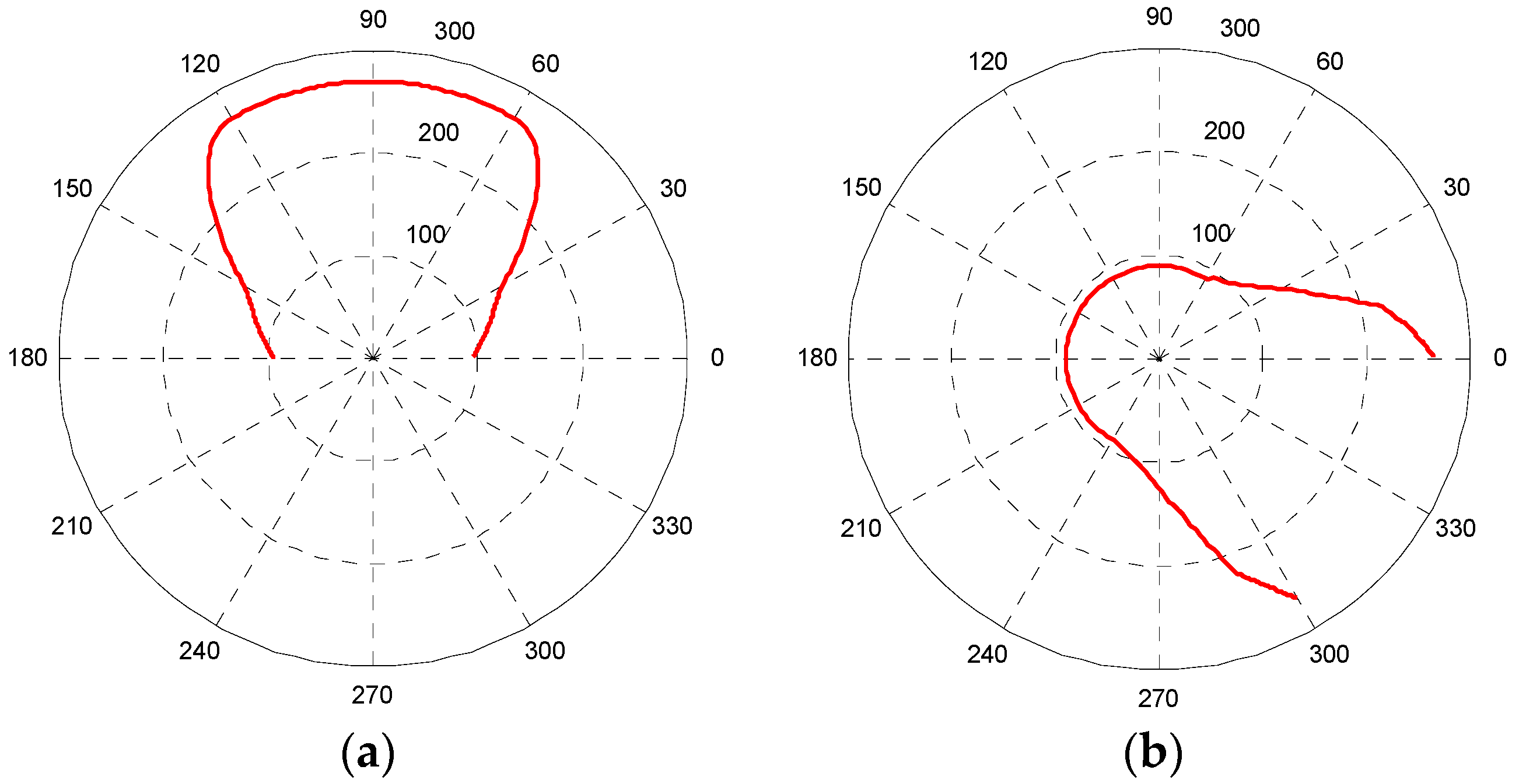
Figure 13.
Fitting curve of non-circular gears. (a) Fitting curve of driving non-circular gear; (b) fitting curve of driven non-circular gear.
Figure 13.
Fitting curve of non-circular gears. (a) Fitting curve of driving non-circular gear; (b) fitting curve of driven non-circular gear.
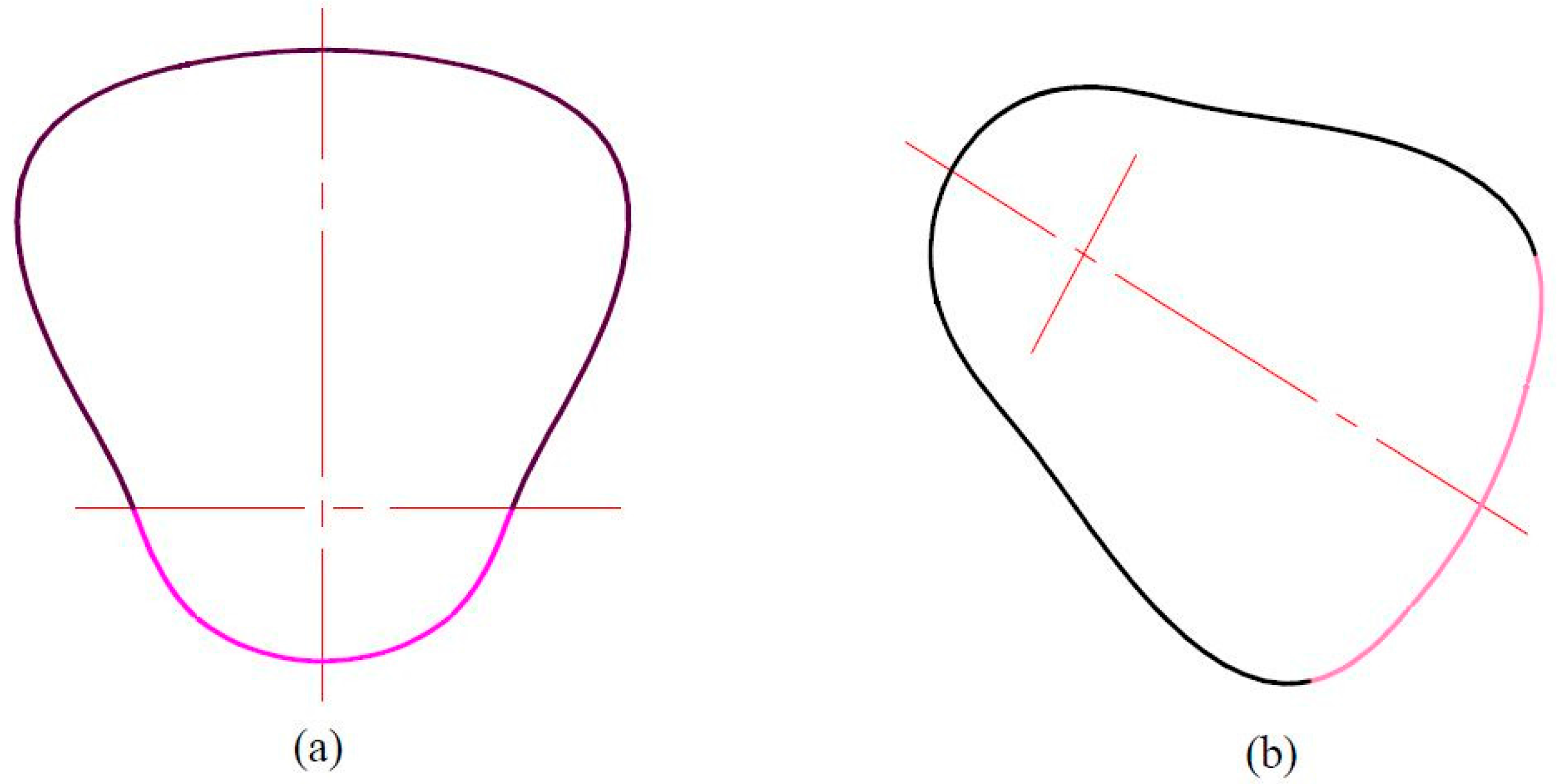
Figure 14.
Non-circular gear profile created by CAXA. (a) Driving non-circular gear; (b) driven non-circular gear.
Figure 14.
Non-circular gear profile created by CAXA. (a) Driving non-circular gear; (b) driven non-circular gear.
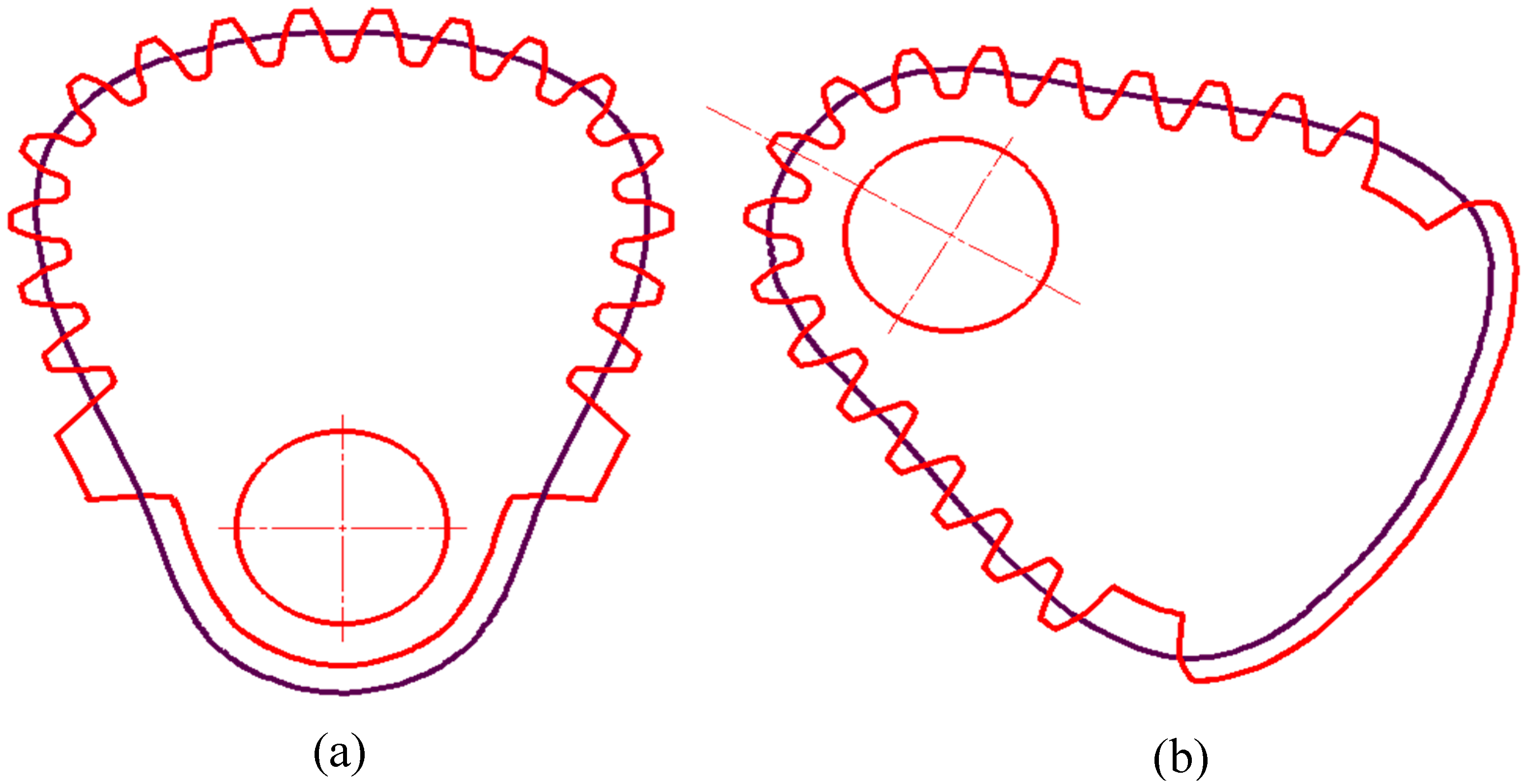
Figure 15.
Simulation video screenshot of the non-circular gear reversing box gear system’s movement.
Figure 15.
Simulation video screenshot of the non-circular gear reversing box gear system’s movement.
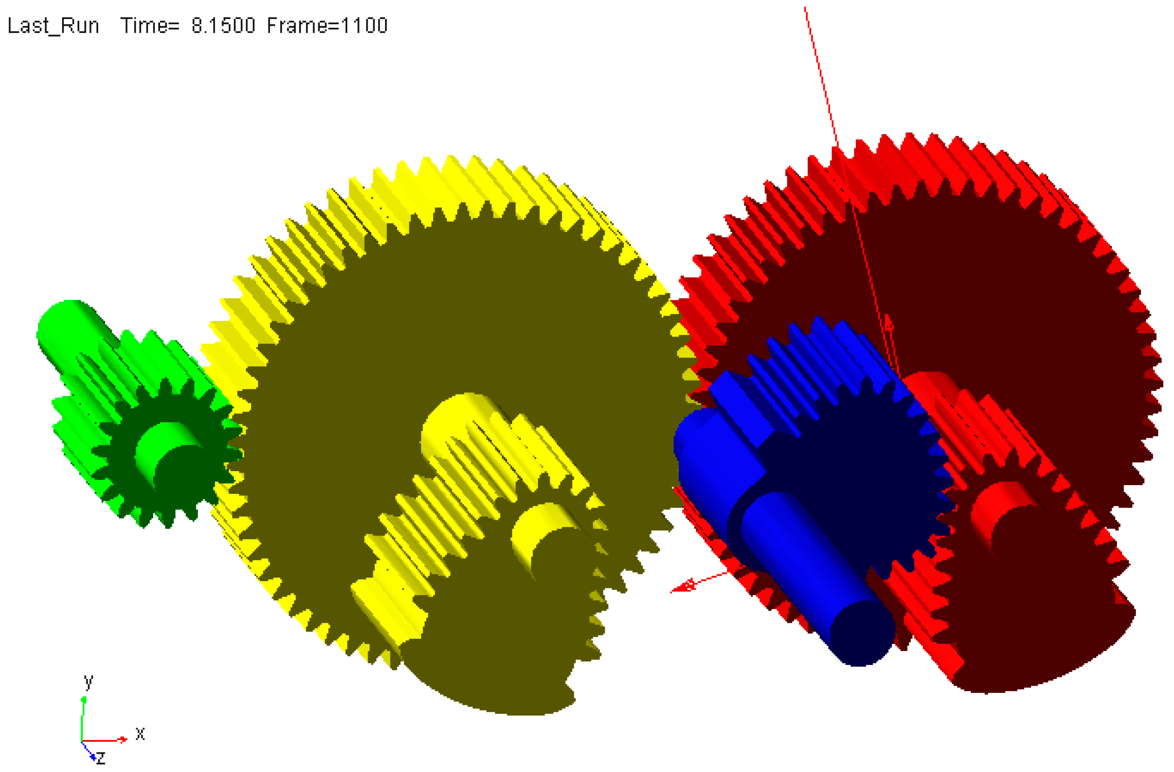
Figure 16.
Simulation curve of output shaft speed of the non-circular gear reversing box.

Figure 17.
Filtered simulation curve of output shaft speed of the non-circular gear reversing box.

Figure 18.
Theoretical calculation value of output shaft speed of the non-circular gear reversing box.
Figure 18.
Theoretical calculation value of output shaft speed of the non-circular gear reversing box.
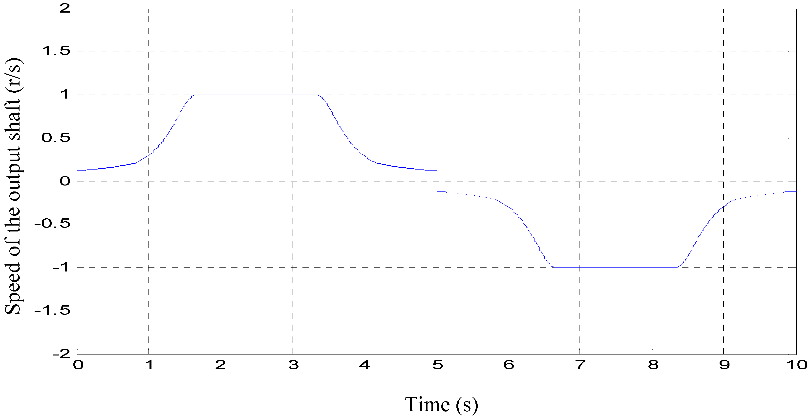
Figure 19.
Polished rod displacement curve that varied with time.

Figure 20.
Model pump system composition diagram.

Figure 21.
Non-circular gear reversing box device.
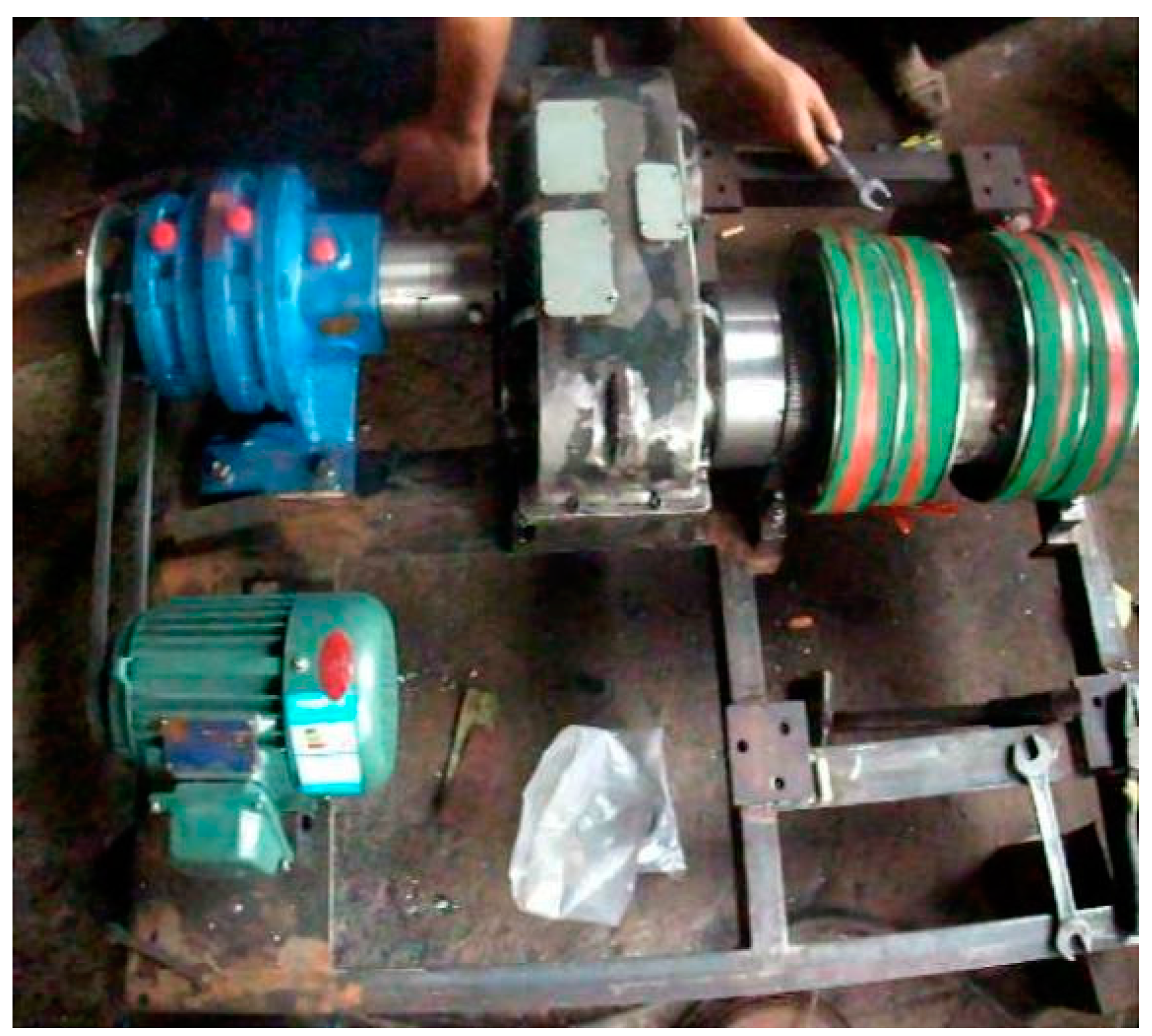
Figure 22.
Field test photo of the proposed CBM exploitation machine.

Table 1.
Main parameters of each gear in the non-circular gear box.
| Gear Name | Modulus | Number of Teeth | Angle of Pressure | Breadth of Tooth (mm) | Number |
|---|---|---|---|---|---|
| driving non-circular gear | 12 | 18 | 20 | 250 | 1 |
| driven non-circular gear | 12 | 17 | 20 | 250 | 2 |
| Standard cylindrical spur gear (big) | 12 | 60 | 20 | 190 | 2 |
| Standard cylindrical spur gear (small) | 12 | 18 | 20 | 200 | 1 |
© 2017 by the authors. Licensee MDPI, Basel, Switzerland. This article is an open access article distributed under the terms and conditions of the Creative Commons Attribution (CC BY) license (http://creativecommons.org/licenses/by/4.0/).
Share and Cite
MDPI and ACS Style
Xu, G.; Hua, D.; Dai, W.; Zhang, X. Design and Performance Analysis of a Coal Bed Gas Drainage Machine Based on Incomplete Non-Circular Gears. Energies 2017, 10, 1933. https://doi.org/10.3390/en10121933
AMA Style
Xu G, Hua D, Dai W, Zhang X. Design and Performance Analysis of a Coal Bed Gas Drainage Machine Based on Incomplete Non-Circular Gears. Energies. 2017; 10(12):1933. https://doi.org/10.3390/en10121933
Chicago/Turabian StyleXu, Guiyun, Dezheng Hua, Weijun Dai, and Xiaoguang Zhang. 2017. "Design and Performance Analysis of a Coal Bed Gas Drainage Machine Based on Incomplete Non-Circular Gears" Energies 10, no. 12: 1933. https://doi.org/10.3390/en10121933
Note that from the first issue of 2016, this journal uses article numbers instead of page numbers. See further details here.