A Novel Digital Control Method of a Single-Phase Grid-Connected Inverter Based on a Virtual Closed-Loop Circuit and Complex Vector Representation

Abstract
:
1. Introduction
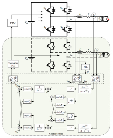
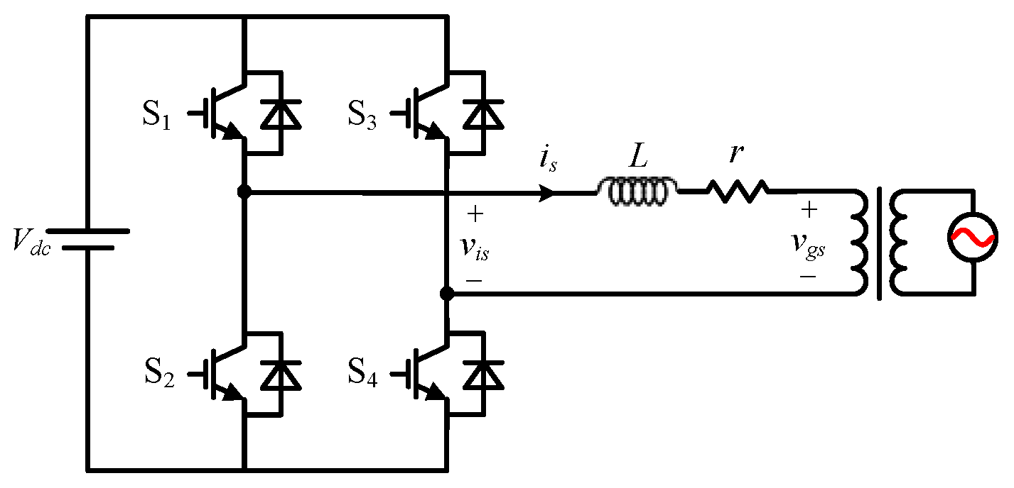
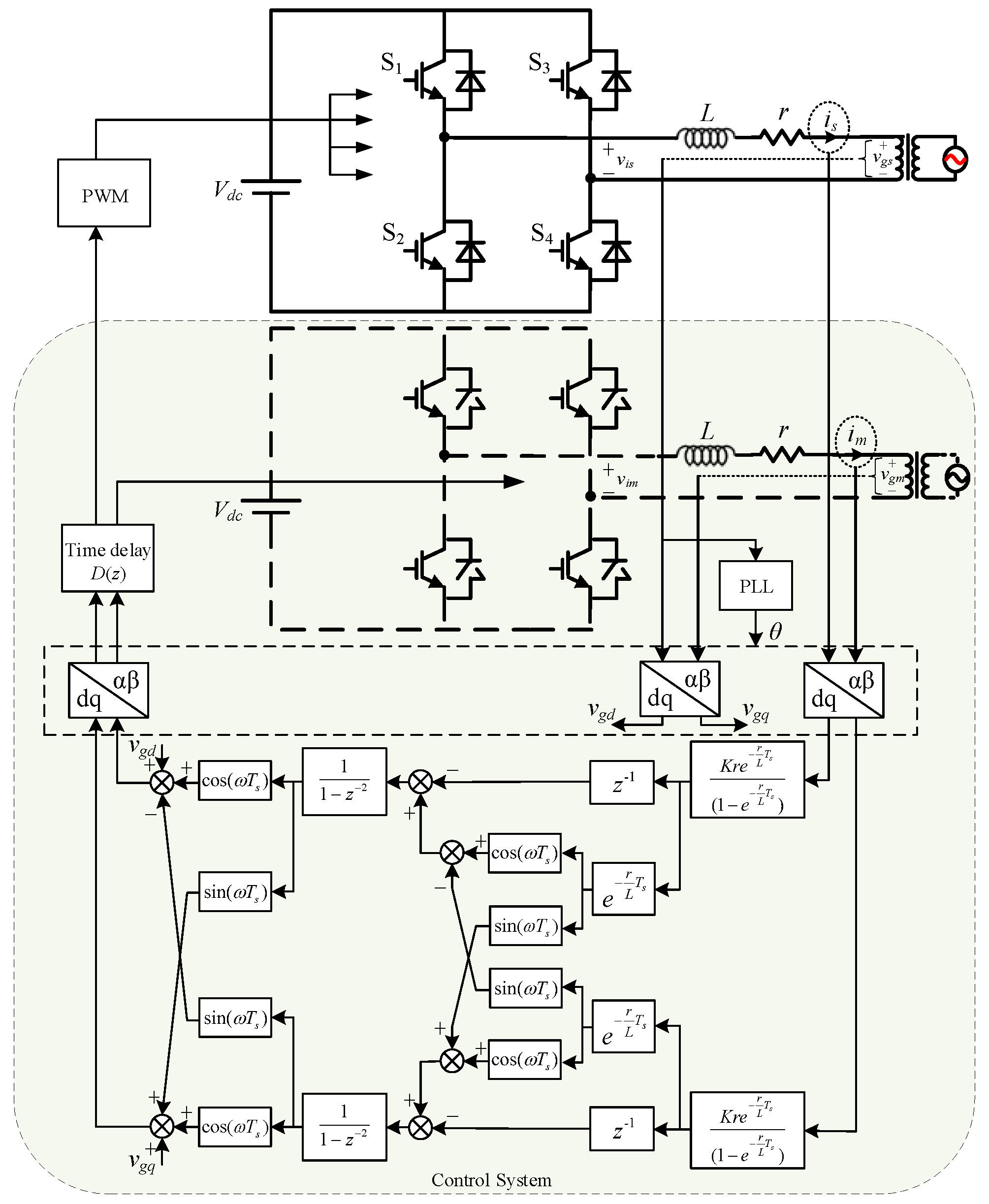
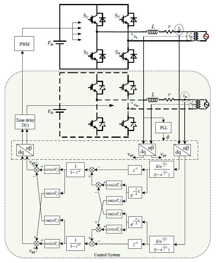
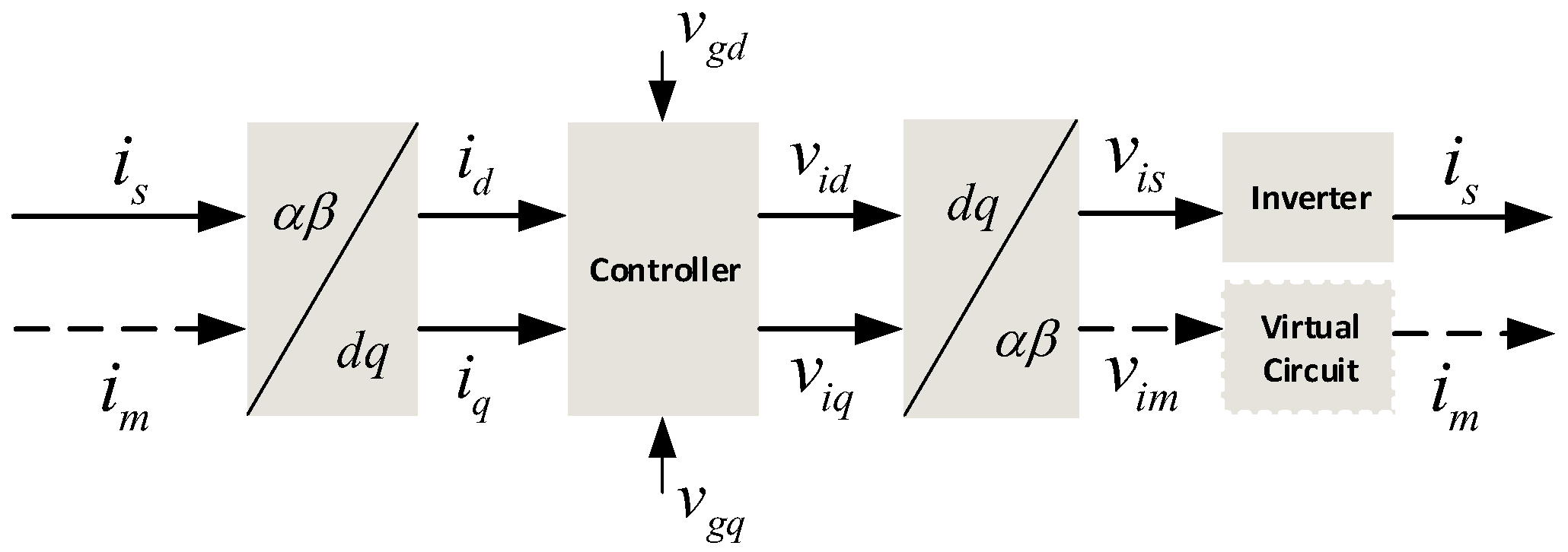
2. Virtual Closed-Loop Construction
3. Discrete Model of the Inverter Considering the Influence of Delay Based on Complex Vectors
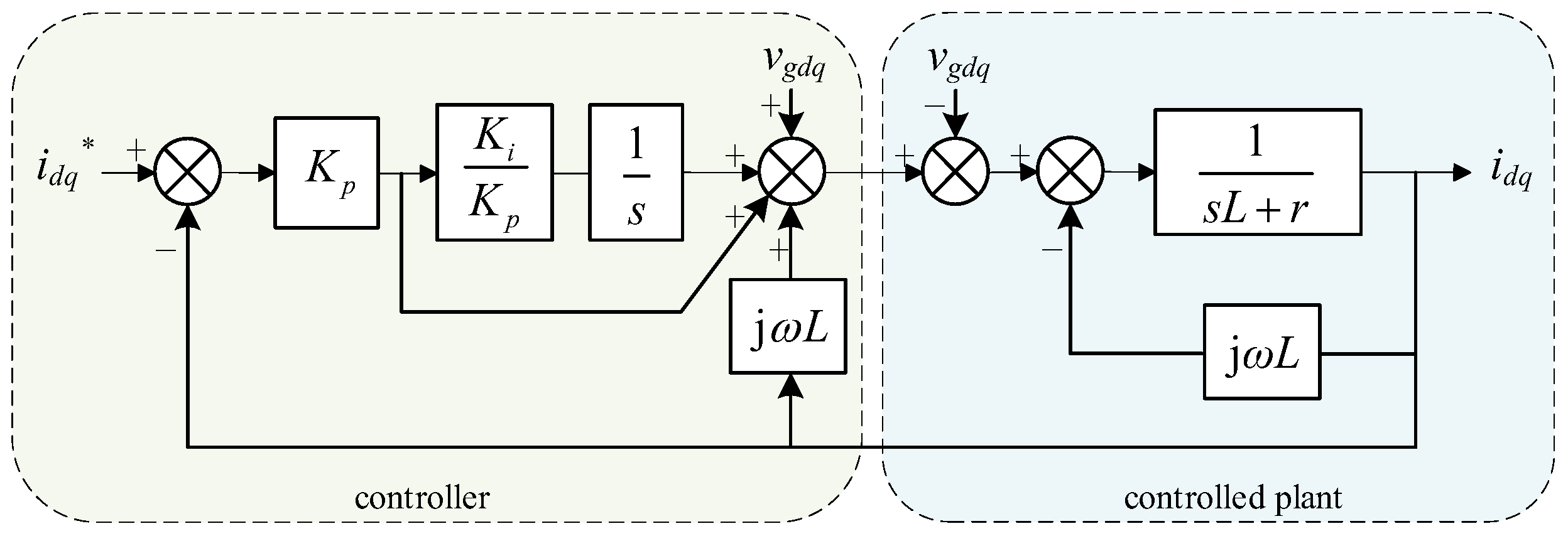
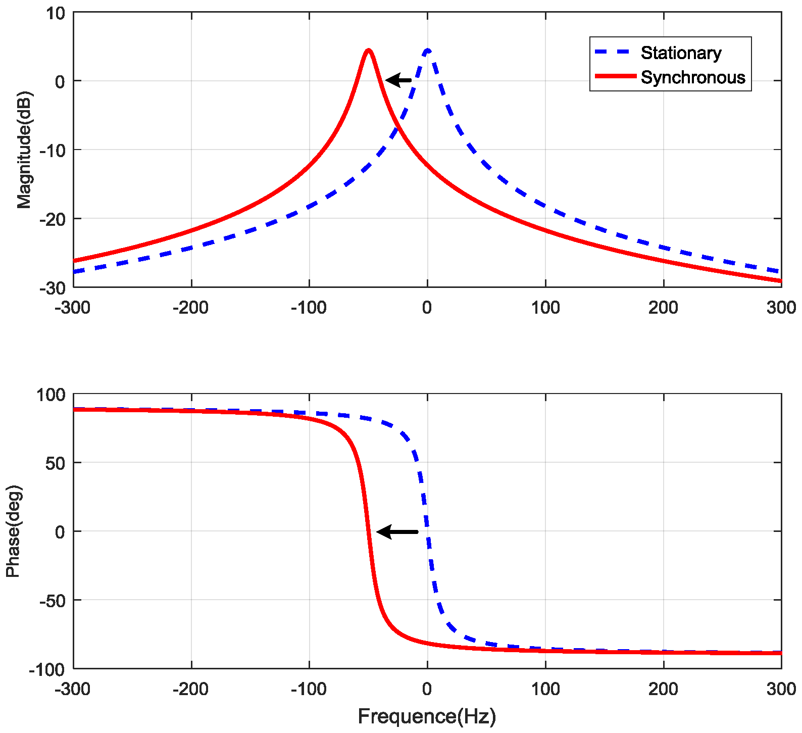
4. Complex Vector-Based Controller
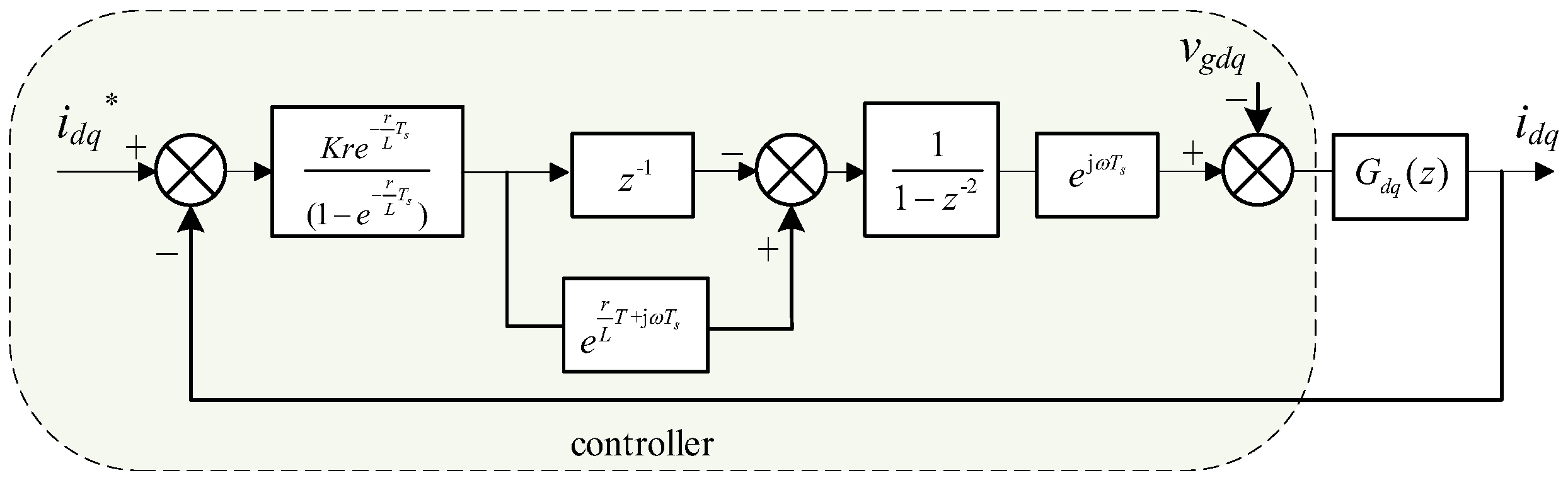
4.1. Discrete Model of the Complex Vector-Based Inverter
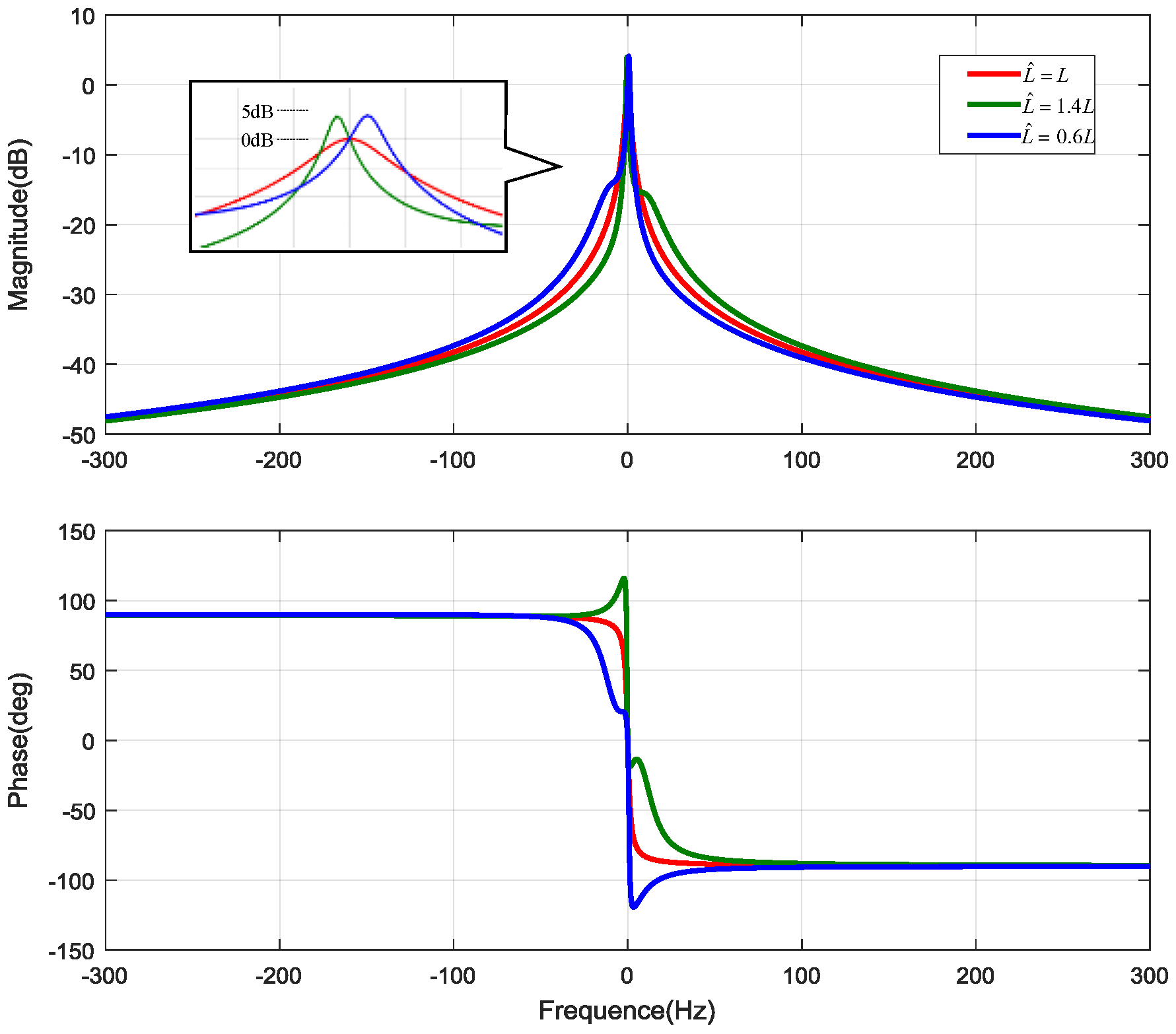
4.2. Controller Design
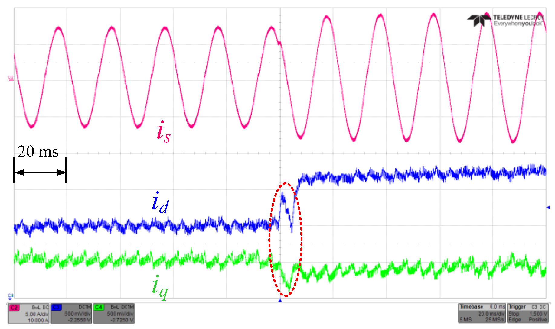
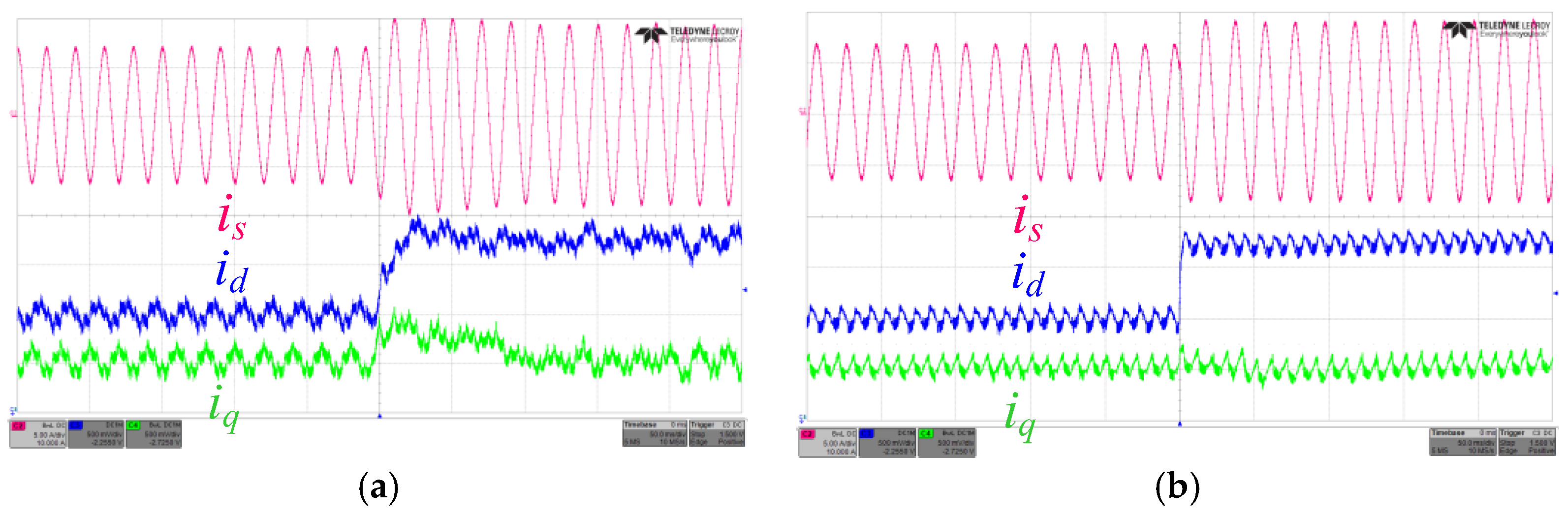
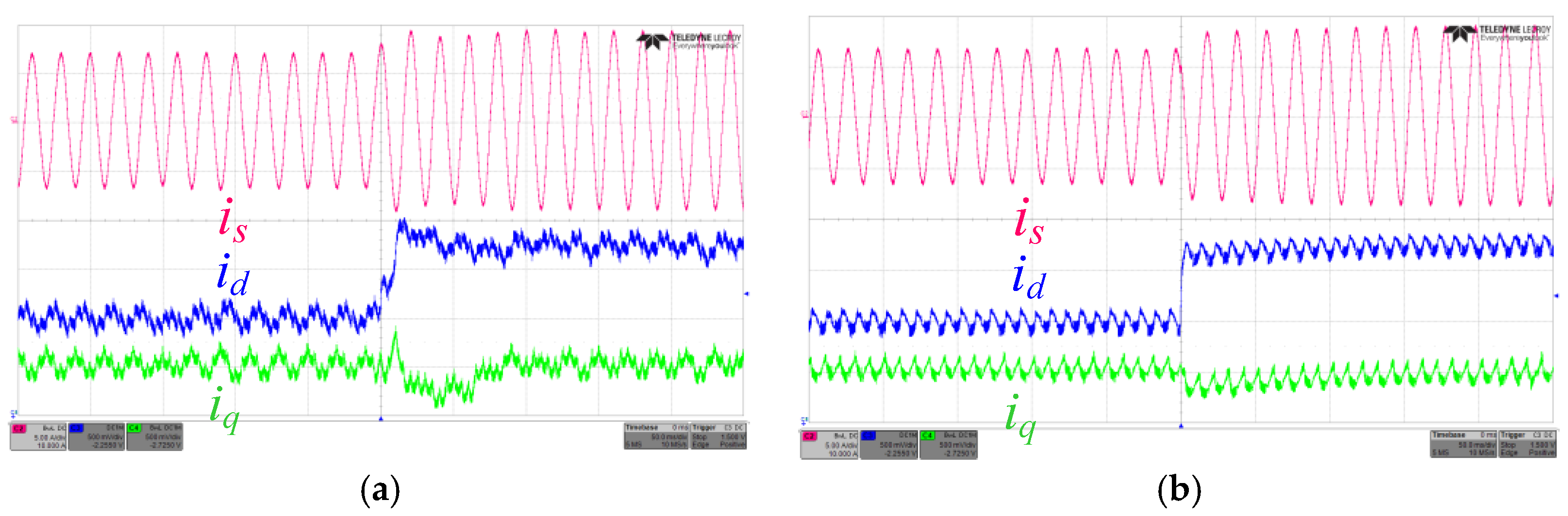
5. Experimental Results
6. Conclusions
Acknowledgments
Author Contributions
Conflicts of Interest
Abbreviations
| Vdc | DC-link voltage |
| L | Grid-tie inductor |
| r | Resistance of the inductor |
| i | Gird-connected current |
| vis | Port voltage of the inverter |
| vgs | Grid voltage of the AC side |
| im | Virtual gird-connected current |
| vim | Port voltage of the inverter in the virtual closed-loop circuit |
| vgm | Virtual grid voltage of the AC side |
| The setting value of the inductance | |
| ω | Angular frequency of the grid voltage |
| Ts | Sampling period |
| G(s) | The transfer function of the controlled plant |
| C(s) | The transfer function of the controller |
| H(s) | The transfer function of the whole system |
References
- Marzband, M.; Parhizi, N.; Savaghebi, M.; Guerrero, J.M. Distributed Smart Decision-Making for a Multimicrogrid System Based on a Hierarchical Interactive Architecture. IEEE Trans. Energy Convers. 2016, 31, 637–648. [Google Scholar] [CrossRef]
- Valinejad, J.; Marzband, M.; Akorede, M.F.; Barforoshi, T.; Jovanović, M. Generation expansion planning in electricity market considering uncertainty in load demand and presence of strategic GENCOs. Electr. Power Syst. Res. 2017, 152, 92–104. [Google Scholar] [CrossRef]
- Marzband, M.; Azarinejadian, F.; Savaghebi, M.; Guerrero, J.M. An Optimal Energy Management System for Islanded Microgrids Based on Multiperiod Artificial Bee Colony Combined With Markov Chain. IEEE Syst. J. 2017, 11, 1712–1722. [Google Scholar] [CrossRef]
- Mortezaei, A.; Simões, M.G.; Busarello, T.D.C. A multi task microgrid inverter based instantaneous Power Theory in islanded and grid-connected modes. In Proceedings of the 2015 IEEE Power & Energy Society General Meeting, Denver, CO, USA, 26–30 July 2015; pp. 1–5. [Google Scholar]
- Marzband, M.; Ardeshiri, R.R.; Moafi, M.; Uppal, H. Distributed generation for economic benefit maximization through coalition formation-based game theory concept. Int. Trans. Electr. Energy Syst. 2017, 27, e2313. [Google Scholar] [CrossRef]
- Marzband, M.; Moghaddam, M.M.; Akorede, M.F.; Khomeyrani, G. Adaptive load shedding scheme for frequency stability enhancement in microgrids. Electr. Power Syst. Res. 2016, 140, 78–86. [Google Scholar] [CrossRef]
- Marzband, M.; Ghazimirsaeid, S.S.; Uppal, H.; Fernando, T. A real-time evaluation of energy management systems for smart hybrid home Microgrids. Electr. Power Syst. Res. 2017, 143, 624–633. [Google Scholar] [CrossRef]
- Yang, Y.; Koutroulis, E.; Sangwongwanich, A.; Blaabjerg, F. Pursuing Photovoltaic Cost-Effectiveness: Absolute Active Power Control Offers Hope in Single-Phase PV Systems. IEEE Ind. Appl. Mag. 2017, 23, 40–49. [Google Scholar] [CrossRef]
- Kadam, S.; Bletterie, B. Balancing the grid with single-phase PV-installations. In Proceedings of the 2017 IEEE 26th International Symposium on Industrial Electronics (ISIE), Edinburgh, UK, 19–21 June 2017; pp. 63–69. [Google Scholar]
- Mastromauro, R.A.; Liserre, M.; Dell’Aquila, A. Control Issues in Single-Stage Photovoltaic Systems: MPPT, Current and Voltage Control. IEEE Trans. Ind. Inform. 2012, 8, 241–254. [Google Scholar] [CrossRef]
- Yu, D.; Li, Y.; Zhou, Y.; Shi, X.; Liu, H.; Huo, M. Fuzzy control of photovoltaic MPPT based on current perturbation. In Proceedings of the 2017 IEEE 2nd Advanced Information Technology, Electronic and Automation Control Conference (IAEAC), Chongqing, China, 25–26 March 2017; pp. 1683–1687. [Google Scholar]
- Ryan, M.J.; Lorenz, R.D. A synchronous-frame controller for a single-phase sine wave inverter. In Proceedings of the APEC 97—Applied Power Electronics Conference, Atlanta, GA, USA, 27 February 1997; Volume 2, pp. 813–819. [Google Scholar]
- Bahrani, B.; Rufer, A.; Kenzelmann, S.; Lopes, L.A.C. Vector Control of Single-Phase Voltage-Source Converters Based on Fictive-Axis Emulation. IEEE Trans. Ind. Appl. 2011, 47, 831–840. [Google Scholar] [CrossRef]
- Zhang, R.; Cardinal, M.; Szczesny, P.; Dame, M. A grid simulator with control of single-phase power converters in D-Q rotating frame. In Proceedings of the IEEE 33rd Annual Power Electronics Specialist Conference, Cairns, Australia, 23–27 June 2002; Volume 3, pp. 1431–1436. [Google Scholar]
- Kim, R.Y.; Choi, S.Y.; Suh, I.Y. Instantaneous control of average power for grid tie inverter using single phase D-Q rotating frame with all pass filter. In Proceedings of the IEEE Industrial Electronics Society Conference, Busan, Korea, 2–6 November 2004; pp. 274–279. [Google Scholar]
- Verdelho, P.; Marques, G.D. DC voltage control and stability analysis of PWM-voltage-type reversible rectifiers. IEEE Trans. Ind. Electr. 1998, 45, 263–273. [Google Scholar] [CrossRef]
- Shen, W.J.; Schroder, S.; Stagge, H.; de Doncker, R.W. Precise modeling and analysis of dq-frame current controller for high power conveters with low pulse ratio. In Proceedings of the IEEE Energy Conversion Congress and Exposition, Raleigh, NC, USA, 15–20 September 2012; pp. 61–68. [Google Scholar]
- Yim, J.-S.; Sul, S.-K.; Bae, B.-H.; Patel, N.; Hiti, S. Modified Current control schemes for high performance permanent magnet AC drives with low sampling to operation frequency ratio. IEEE Trans. Ind. Appl. 2009, 45, 763–771. [Google Scholar] [CrossRef]
- Shi, J.; Shen, J.; Qu, B.; She, H.; Tan, Z. High Performance complex controller for high-power converters with low-pulse ratios. In Proceedings of the International Conference on Power Electronics and ECCE Asia, Seoul, Korea, 1–5 June 2015; pp. 2180–2187. [Google Scholar]
- Holtz, J.; Quan, J.; Pontt, J.; Rodriguez, J.; Newman, P.; Miranda, H. Design of fast and robust current regulators for high-power drivers based on complex state variables. IEEE Trans. Ind. Appl. 2004, 40, 1388–1397. [Google Scholar] [CrossRef]


| Parameter | Variable | Value |
| Grid Voltage | vg | 110 V |
| Grid Frequency | f0 | 50 Hz |
| Grid-Tie Inductor | L | 13.6 mH |
| Resistance of the inductor | r | 0.6 Ω |
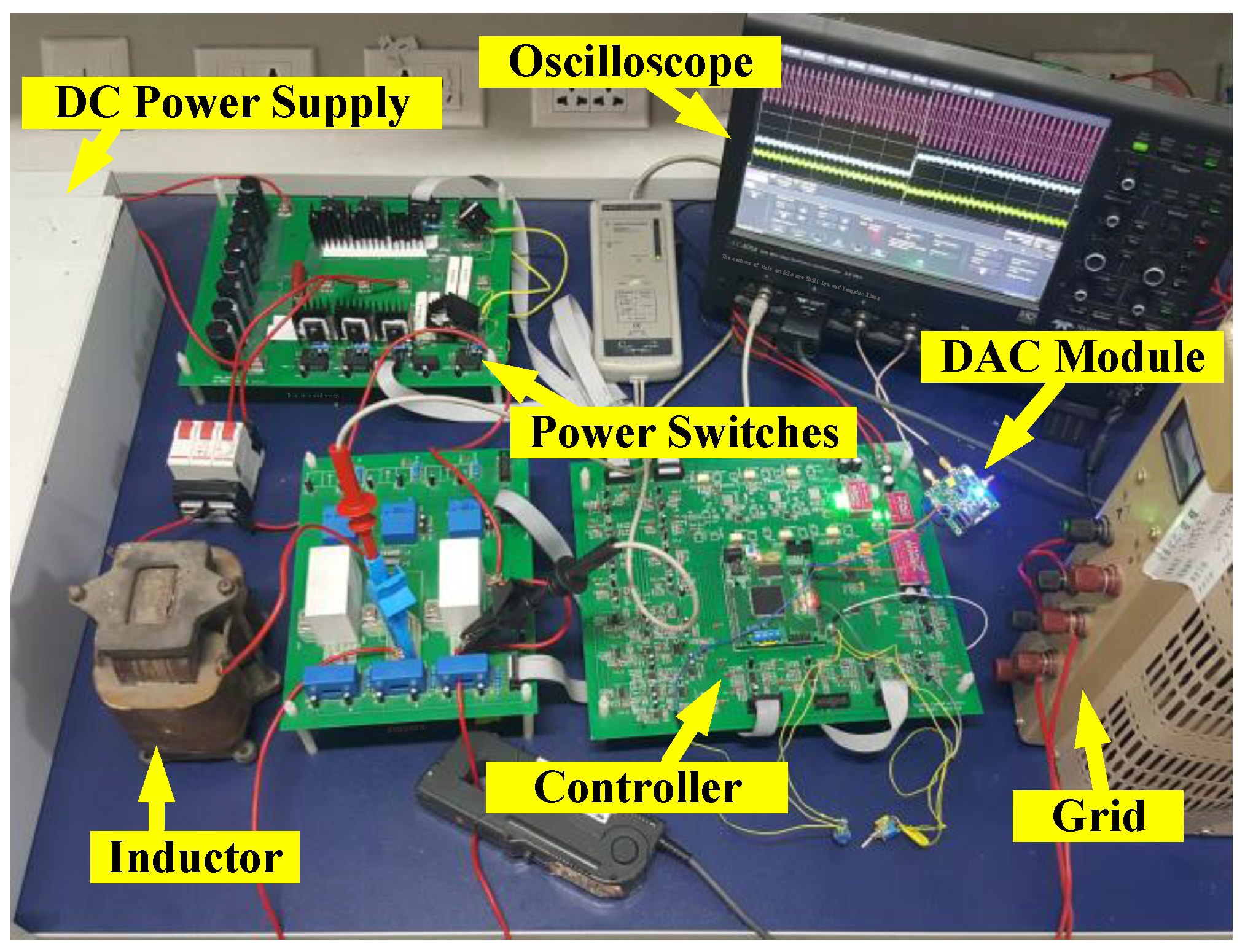
| Switching Frequency | fs | 12 kHz |
| DC-Link Voltage | Vdc | 200 V |
| Components | Part Number | |
| IGBTs(S1–S4) | IKW40T120 | |
| Digital Signal Controller | TMS320F28335 | |
| DC power supply | PSI81500-30 | |
| Current Probe | CP150 | |
| Oscilloscope | HDO4054 | |
© 2017 by the authors. Licensee MDPI, Basel, Switzerland. This article is an open access article distributed under the terms and conditions of the Creative Commons Attribution (CC BY) license (http://creativecommons.org/licenses/by/4.0/).
Share and Cite
Xie, K.; Hu, G.; Yi, H.; Lyu, Z.; Xiang, Y. A Novel Digital Control Method of a Single-Phase Grid-Connected Inverter Based on a Virtual Closed-Loop Circuit and Complex Vector Representation. Energies 2017, 10, 2068. https://doi.org/10.3390/en10122068
Xie K, Hu G, Yi H, Lyu Z, Xiang Y. A Novel Digital Control Method of a Single-Phase Grid-Connected Inverter Based on a Virtual Closed-Loop Circuit and Complex Vector Representation. Energies. 2017; 10(12):2068. https://doi.org/10.3390/en10122068
Chicago/Turabian StyleXie, Kun, Gangyi Hu, Hong Yi, Zhibi Lyu, and Yangxiao Xiang. 2017. "A Novel Digital Control Method of a Single-Phase Grid-Connected Inverter Based on a Virtual Closed-Loop Circuit and Complex Vector Representation" Energies 10, no. 12: 2068. https://doi.org/10.3390/en10122068