Article

Impact of Distributed Generation Grid Code Requirements on Islanding Detection in LV Networks

1
Department of Industrial Engineering, University of Padova, 35131 Padova, Italy
2
e-distribuzione Società per azioni (S.p.A.), Via Ombrone 2, 00198 Roma, Italy
*
Author to whom correspondence should be addressed.
Energies 2017, 10(2), 156; https://doi.org/10.3390/en10020156
Submission received: 8 November 2016 / Revised: 20 December 2016 / Accepted: 19 January 2017 / Published: 26 January 2017

Abstract

:
The recent growing diffusion of dispersed generation in low voltage (LV) distribution networks is entailing new rules to make local generators participate in network stability. Consequently, national and international grid codes, which define the connection rules for stability and safety of electrical power systems, have been updated requiring distributed generators and electrical storage systems to supply stabilizing contributions. In this scenario, specific attention to the uncontrolled islanding issue has to be addressed since currently required anti-islanding protection systems, based on relays locally measuring voltage and frequency, could no longer be suitable. In this paper, the effects on the interface protection performance of different LV generators’ stabilizing functions are analysed. The study takes into account existing requirements, such as the generators’ active power regulation (according to the measured frequency) and reactive power regulation (depending on the local measured voltage). In addition, the paper focuses on other stabilizing features under discussion, derived from the medium voltage (MV) distribution network grid codes or proposed in the literature, such as fast voltage support (FVS) and inertia emulation. Stabilizing functions have been reproduced in the DIgSILENT PowerFactory 2016 software environment, making use of its native programming language. Later, they are tested both alone and together, aiming to obtain a comprehensive analysis on their impact on the anti-islanding protection effectiveness. Through dynamic simulations in several network scenarios the paper demonstrates the detrimental impact that such stabilizing regulations may have on loss-of-main protection effectiveness, leading to an increased risk of unintentional islanding.

1. Introduction

In many countries, different grid codes have been recently approved with the scope of defining the connection rules for passive and/or active end-users. At European level, the technical specifications CENELEC TS 50549-1 and CENELEC TS 50549-2 [1,2] contain the recommendations for the connection of generating plants, with injected current above 16 A, to the distribution networks at low voltage (LV) and medium voltage (MV), respectively. Furthermore, micro-generating plants with rated current below 16 A connected to LV networks are regulated by the European Standard CENELEC EN 50438 [3]. In the Italian domain, standards CEI 0-16 [4] and CEI 0-21 [5] introduce the technical schemes and rules for the connection of passive and active users to the MV and LV networks respectively, including in the latest version the simultaneous presence of both distributed generators (DGs) and energy storage systems (ESSs). Both of them could be involved by the distribution system operator (DSO) in regulating the network operating conditions, e.g., as illustrated in [6,7,8,9].
The scope of these documents is to define the rules to ensure the integration of DGs and ESSs in the present electrical networks with the highest compatibility level. Local generators and storages connected to LV and MV grids are required to participate in supporting the network stability. The injected active power regulation (named P/f regulation) is recommended to contribute to the frequency stability of the main grid, whereas the reactive power regulation (named Q/V regulation) is focused on the control of voltage levels in the distribution network [10]. Even if the Q/V regulation could have weak effects on controlling the local voltage in LV systems (where a P/V regulation could be more suitable [11,12], depending on the R/X ratio [13]), this function is implemented by present grid codes also on LV DGs [5], and may provide a significant a support for the MV system. Furthermore, active and reactive power modulation of DGs connected both at the LV and the MV distribution systems could be exploited in order to face voltage imbalance issues [14,15,16,17]. Furthermore, currently applied standards define wider frequency and voltage operating ranges for the interface protection systems (IPSs) to avoid the untimely disconnection of the generating plants and, consequently, to prevent balancing actions on the transmission grid. Additionally, this work discusses other types of stabilizing functions, such as the fast voltage support (FVS) and the synthetic inertia (SI): although not yet required by grid codes, they have been proposed by technical documents and literature.
In steady-state conditions the advantages of these improvements are well known. Conversely, the paper demonstrates that, in the case of faults or switching operations (due to network maintenance, reconfigurations, false circuit breakers tripping, etc.), stabilizing functions provided by DGs may lead all, or a portion of, the LV system to autonomously operate disconnected from the MV network. In particular, in several network scenarios (considering different imbalance levels between load and generation in the LV portion), stabilizing functions have a role in containing voltage (V) and frequency (f) variations after the islanding event. This inhibits the correct trip of currently required loss-of-main protections, resulting in an uncontrolled islanding operation for a not negligible duration. Dynamic simulations have been carried out in the DIgSILENT PowerFactory environment. Already-defined stabilizing functions and IPS specifications are set referring to the present Italian grid code [5], in accordance with the CENELEC guidelines. Even if the paper refers to a national standard, it is worth noting that national grid codes of European counties are evolving toward harmonization with CENELEC guidelines.
In the following, Section 2 summarizes the present requirement for LV DGs, Section 3 introduces additional stabilizing functions under discussion, Section 4 illustrates the case study and network models, whereas Section 5 reports and discusses the obtained results, demonstrating the impact of stabilizing functions on loss-of-main protection effectiveness, focusing on LV networks.

2. Present Standard and Requirements for Distributed Generators (DGs) Connected to Low Voltage (LV) Networks

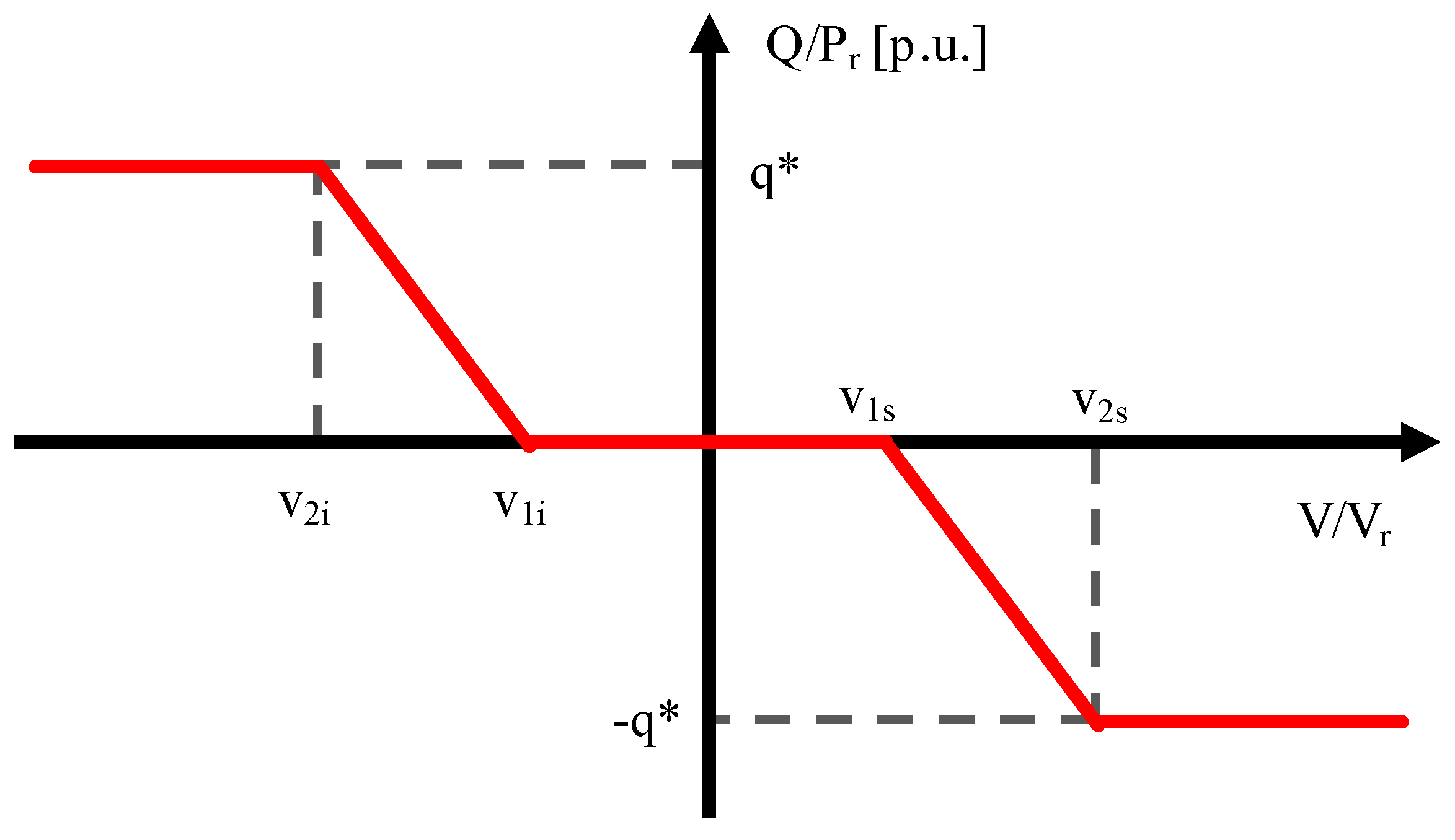
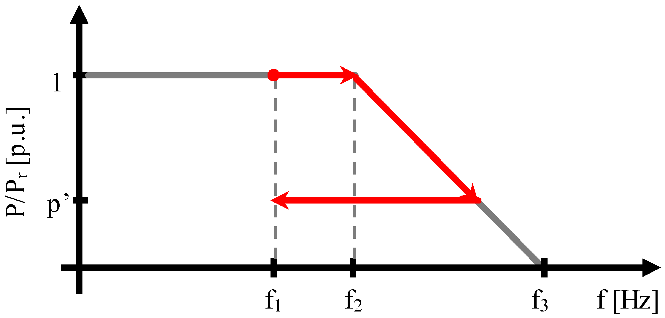
2.1. P/f and Q/V Regulations

The DSO can require active users to participate in the network frequency regulation by modulating the active power production. In case of over-frequency, the generator is called to reduce its active power injection according to a droop curve, with a statism S0 = 2.4%, as reported in [5]. The active power reduction is based on the measured local frequency and is applied according to the P/f characteristic shown in Figure 1. Once the frequency perturbation ends and the frequency derivative becomes negative, the static generator has to maintain the reached active power level p’ for a duration of 300 s, to avoid frequency oscillations, before returning to the initial level (active power hysteresis).
Participation to the voltage regulation is obtained by suitably managing the reactive power injection according to the Q/V characteristic depicted in Figure 2. As long as the measured voltage remains within a range near to the nominal value, the generator reactive contribution is null. Otherwise, the generating unit behaves as a capacitive or an inductive load in the case of under or over-voltage, respectively. The regulating function Q/V is not required if the DG rated power is smaller than 11.08 kW (corresponding to 16 A). Considering present Italian grid code requirements [5], values of the parameters adopted in this work are summarized in Table 1 (with reference to Figure 1 and Figure 2).

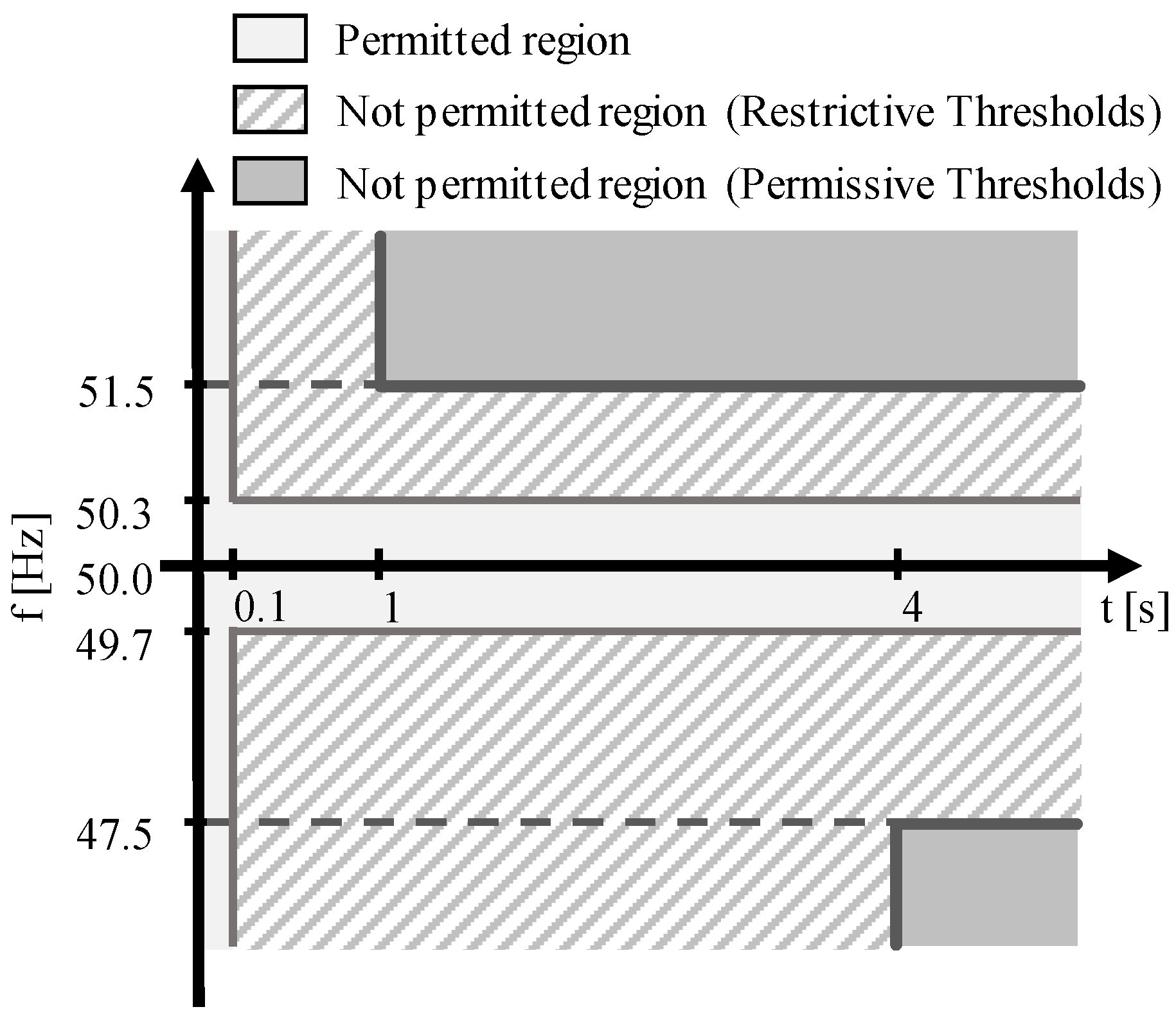
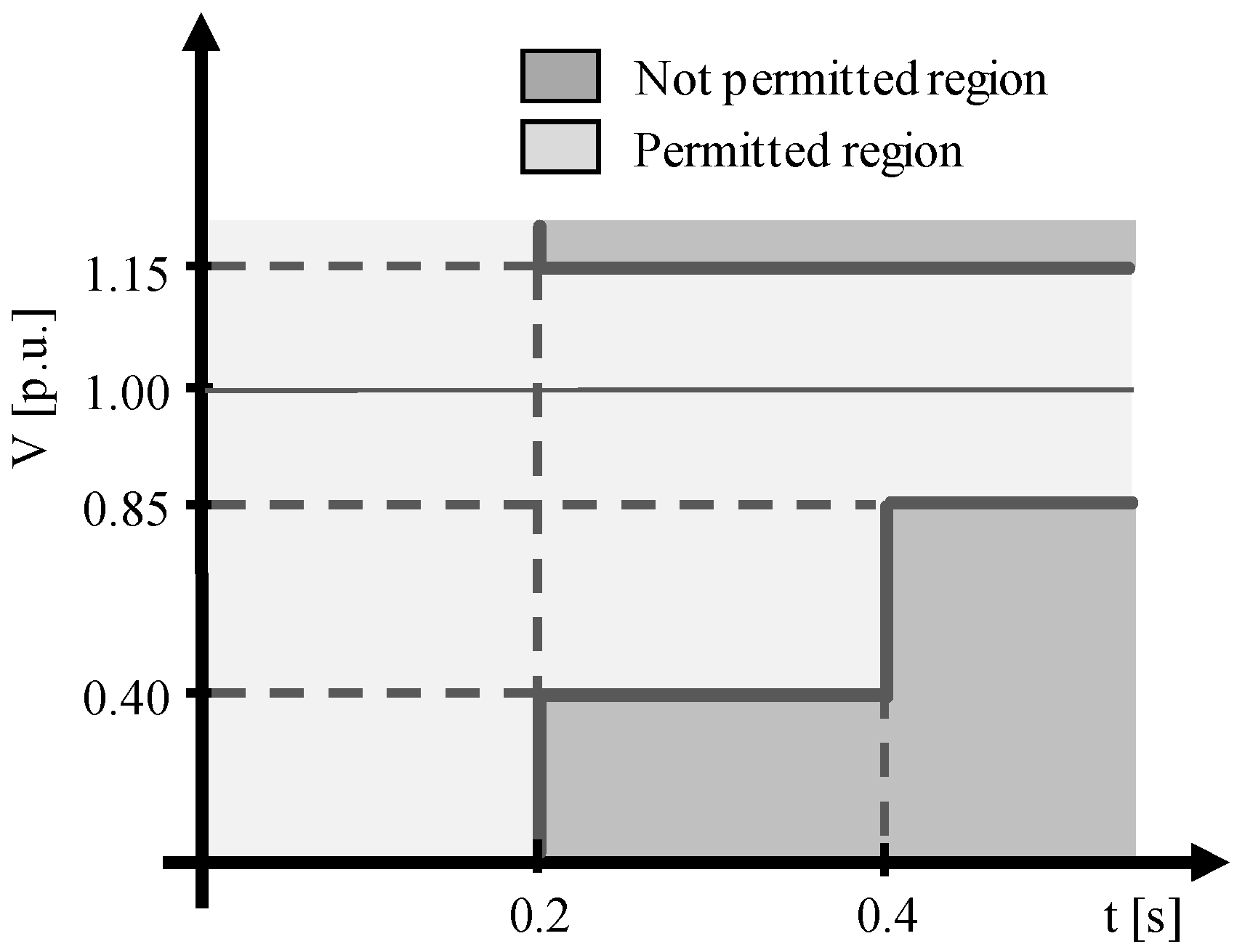
2.2. Interface Protection System

Under steady-state or slowly varying regimes, the benefits in terms of power quality of the above-mentioned DGs’ stabilizing actions are well established. However, the potential risk of uncontrolled islanding on distribution networks needs to be kept under control. Unintentional islanding is a dangerous condition for various reasons, as: (i) the incorrect intervention of protection systems; (ii) the risk of devices damage; (iii) the risk to the safety of both end-users and the network maintenance staff. Referring to Italian standards, several studies in this field have been carried out demonstrating, through both analytical and numerical analysis, the increased risk of undetected islanding operations in active distribution networks in accordance with CEI 0-21 requirements [18,19,20,21,22].
In addition, Italian rules for MV networks introduce protection systems with the automatic reclosing logic in order to limit the duration of network outages in case of non-permanent faults. The reclosing cycle is usually operated in the primary substation on the switches supplying the MV feeders and can interfere with the IPS of active end-users. The possibility of an automatic reclosing, with a part of the feeder locally supplied by DG units connected in the LV networks, is not negligible [23]. This event generally coincides with an out-of-synchronism state as the main grid and the islanded network could have different frequencies and phase angles [21]. The effects on rotating generators of the out-of-synchronism reclosing are investigated in [22].
For these reasons, loss-of-main protections and techniques have been considered and developed to avoid unintentional and uncontrolled islanding conditions in the case of grid failures or fault conditions. Anti-islanding solutions are classified in passive or active ones [24]: the first type operates de-energizing the generator in case of voltage and/or frequency values outside allowed ranges, whereas the second is constituted by active devices. In the first case, an innovative solution is presented in [25], whereas, for the second technology, different methods could be adopted as the frequency shift method [26] or the remote control [27]. In particular, according to Italian standards, additional procedures have been proposed [28,29].
The present grid code for DGs connected to LV networks [5] defines the IPS as a passive loss-of-main protection forcing the disconnection of the generator and the optional storage system if frequency or voltage at the connection point are outside the pre-set ranges.
The frequency protection (Code 81 in ANSI/IEEE classification, where ANSI is the American National Standards Institute) can operate with either restrictive or permissive thresholds, depending on an external signal from DSO, as depicted in Figure 3. In the restrictive mode, the protection disconnects the generator from the grid if the frequency is maintained out of the range 49.7–50.3 Hz for more than 100 ms. Otherwise, in the permissive mode, the limits are 47.5 and 51.5 Hz, for 4 and 1 s, respectively.
Under-voltage and over-voltage protections (Code 27 and Code 59, respectively, in the ANSI/IEEE classification) implement the fault voltage ride through (FVRT) logic. The required voltage protection thresholds are reported in Figure 4. With this approach, rapid voltage variations are allowed to preserve the operation of DG units during faults, avoiding untimely IPS intervention. Both over-voltage and under-voltage transients are admitted for a limited duration.

3. Additional LV DGs Stabilizing Functions

The regulating functions described in Section 2.1 must be installed on new DGs connected to the LV network. Furthermore, additional functions are presently under discussion, having been proposed for consideration by either European technical documents (on the basis of similar standards applied to MV distribution networks) or the literature. Since these proposed stabilizing functions, briefly described below, would be integrated in addition to existing P/f and Q/V regulations, their behaviour and impact on network stability and islanding detection are required to be investigated in detail.

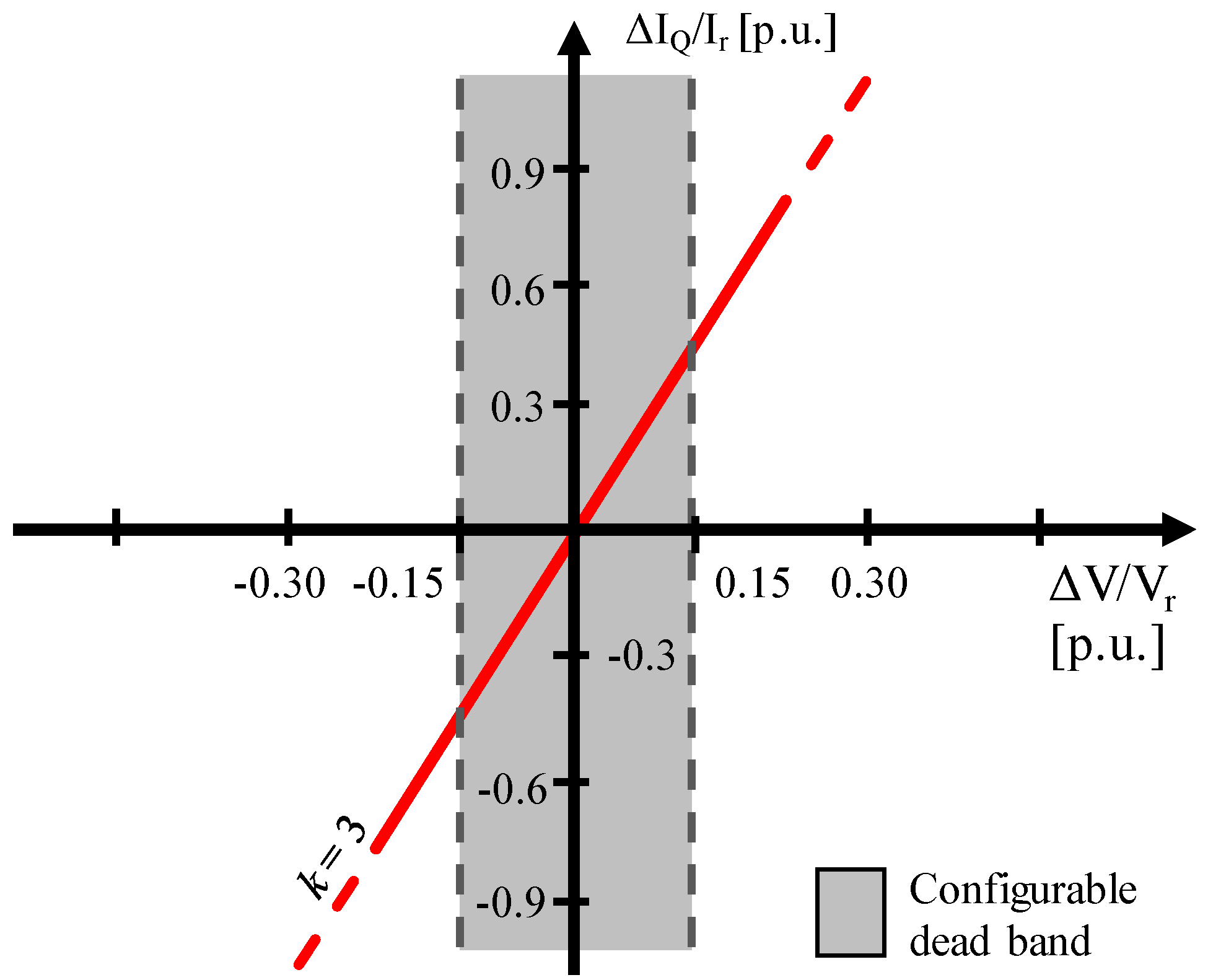
3.1. Voltage Support Strategies

In the case of faults, the generating units should have the capability to rapidly contribute in supporting the voltage stability by exchanging additional reactive power with the grid, within the generator current injection limit (DG capability). This function, called fast voltage support (FVS), is exhaustively detailed in [2] for MV grids. In this work, FVS is applied to LV networks to highlight that, although the regulation is effective in a wider scope than just during faults, it could introduce an increased risk of failure in detecting islanded operating conditions.
Reactive current injections of positive and negative sequence (ΔIQ1 and ΔIQ2) are required in case of voltage step variations of the positive and the negative sequence components of the fundamental voltage (ΔV1 and ΔV2, respectively). The step variations are evaluated with respect to the previous minute average values. A constant k relates the voltage perturbations to the current injections, as defined in Equations (1) and (2):
Δ I Q 1 = k Δ V 1
Δ I Q 2 = k Δ V 2
A configurable dead band can be introduced for a range of voltage values close to the nominal voltage. These recommendations are summarized in Figure 5, in which k is assumed to be equal to 3.
The dynamic voltage regulation can be provided with various methods or technologies, with either large lumped static var systems (SVSs) in primary or secondary substations, or several smaller distributed devices. The greater effectiveness of the latter is proved in [30] and the implementation of voltage regulating capabilities on DGs is widely recommended. The regulating function would operate in case of both grid faults and disconnections from the main grid, which means reducing the voltage perturbation, thus limiting, in the latter case, the effectiveness and reliability of presently-required loss-of-main protections.
An analysis of the voltage support function through reactive power injections by static generators (in particular photovoltaic) is presented in [31] referring to German grid codes. Focusing on the effects of voltage regulation in LV networks, other results are presented in [32]. Furthermore, the management of the local generators reactive power at positive and negative sequences allows, respectively, to control voltage amplitude and to balance phase voltages [33,34]. In [35], a parametrical analysis of voltage regulation through DGs reactive power injections has been carried out as a function of the network R/X ratio to maximize its effectiveness.
In this paper, the dynamic voltage contribution in supporting network voltage during faults, focusing on its effects on the installed IPSs, is examined in depth.

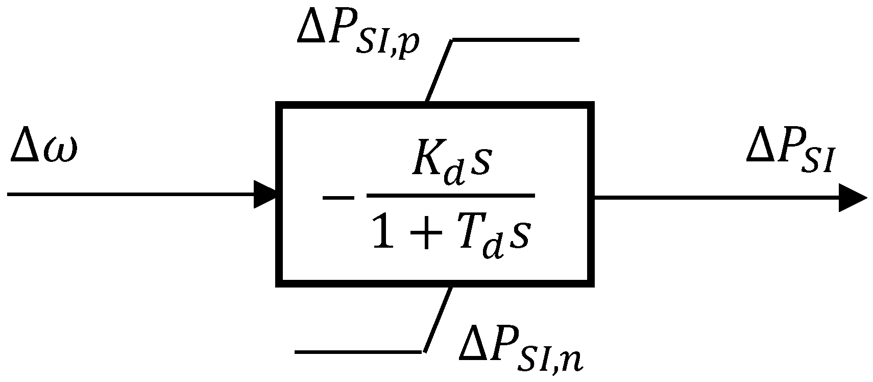
3.2. Synthetic Inertia

In addition to the power regulations required, or suggested, by national and international technical standards, a further active power management method is here considered, named synthetic inertia or inertia emulation. Usually, inertia emulation is implemented in modern wind turbines (WTs) and its impact on frequency stability is widely demonstrated [36,37,38]. In this work the synthetic inertia is supposed to be applied also to static generators connected to the LV distribution network (e.g., photovoltaic plants) in order to investigate its impact on frequency oscillations and islanding detection.
Usually static and electronic interfaced generators are designed to be insensitive to frequency variations at their connection node and, consequently, evolve without inertial response. Even if a P/f regulation is required in steady-state operating conditions, present static DGs do not regulate injected power to support network stability during fast frequency perturbations (e.g., with peak value lower than f1, referring to Figure 1), as intrinsically performed by rotating generators thanks, to their mechanical inertia.
The inertia effect could be synthetically implemented in static generators by requiring electronic converters to contribute in case of frequency perturbations. In particular, an extra active power injection (or absorption) could be requested to simulate the inertial behaviour of synchronous generators. The amount of this contribution is proportional to the network frequency derivative and improves the electrical system transient stability.
Whereas, in the case of wind turbines, the additional active power is retrieved from the blades rotating inertia, in case of static generators the synthetic inertia function could be provided by an associated small scale local storage system (e.g., a storage unit normally operating to maximize the DG self-consumption). Methodologies for the estimation of the energy storage system size to provide adequate inertia emulation, in addition to other stabilizing regulations, are presented in [39,40].
With reference to the most widely used models illustrated in [37,38], the additional active power ΔPSI is assessed starting from Δω (frequency deviation measured by a phase-locked loop, PLL) through a derivative block combined with a low-pass filter, as represented in Figure 6. Thus, the incremental active power is proportional to the frequency deviation derivative. The proportional constant Kd is related to the desired inertia constant H the device is required to have. The denominator pole is necessary to avoid any response to very fast frequency variations due to measurement noise. Values ΔPSI,n and ΔPSI,p define the operative band that represents the maximum participation of the synthetic inertia function.

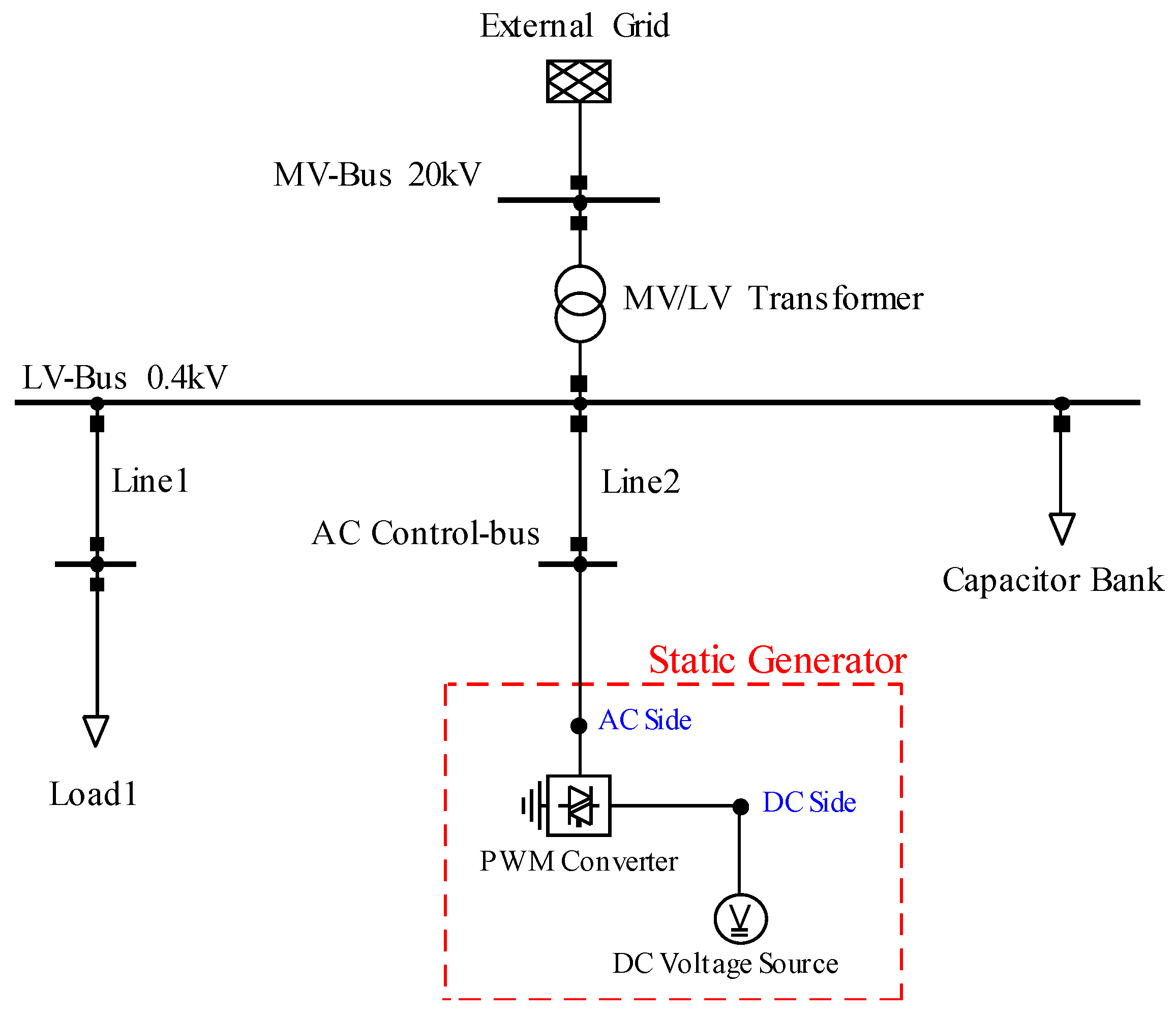
4. Low Voltage Network Study Case

A simple, yet representative, portion of a typical LV network has been considered to assess the time evolution of voltage and frequency following a contingency, when one or more local static generators provide the regulating functions, such as P/f, Q/V, FVS, and synthetic inertia, according to the standards.
The effectiveness and the reliability of the IPS operation have been investigated with specific focus on: (i) the unintentional islanding formation (due to switching operations); and (ii) the consequences of a short circuit fault on the MV side of the distribution transformer. A test case has been implemented in the DIgSILENT PowerFactory environment, where requirements of grid codes (in terms of stabilizing functions and IPS characteristics) and additional features under discussion have been modelled making use of the native software simulation language.

4.1. Network Data

The network scheme implemented as case study has been intentionally kept simple to better investigate the possible interactions among stabilizing functions applied to DGs, generator protections, network equivalent load, and reactive compensation. In this way, possibly misleading factors, such as different dynamic behaviours of loads or voltage variations between different nodes along distribution feeders, are excluded from the study. However, results obtained with reference to the schematic network described below can be easily extended to real, larger, and more detailed LV feeders.
The equivalent LV system depicted in Figure 7 consequently offers results that are representative of different domains:
  • An entire LV network supplied by the MV/LV transformer in the secondary substation: in this case, the modelled components are network equivalent representations of the overall load [41,42,43] and connected DG units.
  • An active end-user: the unexpected islanding is analysed in terms of potential safety issues for untrained people.
Three main devices compose the equivalent LV system (0.4 kV rated voltage): (i) a LV load (“Load1”); (ii) a reactive compensation device (“Capacitor Bank”); and (iii) a DG unit (“Static Generator”, e.g., a photovoltaic plant). The DG unit is modelled as a DC voltage source interconnected with the AC bus “LV-Bus” through a pulse-width modulation inverter (PWM Converter). The overall system comprises the MV main grid equivalent representation (“External Grid”, rated voltage 20 kV) and a MV/LV distribution transformer (group Dyn11 with the star point earthed on the LV side, Sn = 400 kVA).
The centralized reactive compensator “Capacitor Bank” is directly connected to the node “LV-Bus”, downstream the transformer (LV side) and is modelled as a standard load with a dedicated control scheme regulating the reactive power set-point (whereas its active power set-point is equal to zero). Both the load and the generating group are connected to the secondary substation through dedicated three-phase lines. Thus, these components are considered representative of passive and active users, respectively: in the present work, lines have aluminium sections of 185 mm2 and length of 300 m.
The component “Load1” models all of the passive end-users distributed along the LV feeder: it has a 50 kW nominal active power absorption Pn and a power factor equal to 0.928. The behaviour is both static (40% of Pn) and dynamic (60% of Pn), with dependence on voltage and frequency at the connection node (load fundamental characteristics taken from [43,44]).
Even if considered by current standards, the test case does not intentionally include storage systems directly connected to the LV network, to highlight the effects of the sole DG on the undesired islanding of LV network portions. In general, ESSs are expected to provide an additional stabilizing contribution, since they are able to provide quick active bidirectional power flows, which means regulating both under-frequency and over-frequency transients. Furthermore, they could have a role in balancing reactive power after the separation event.

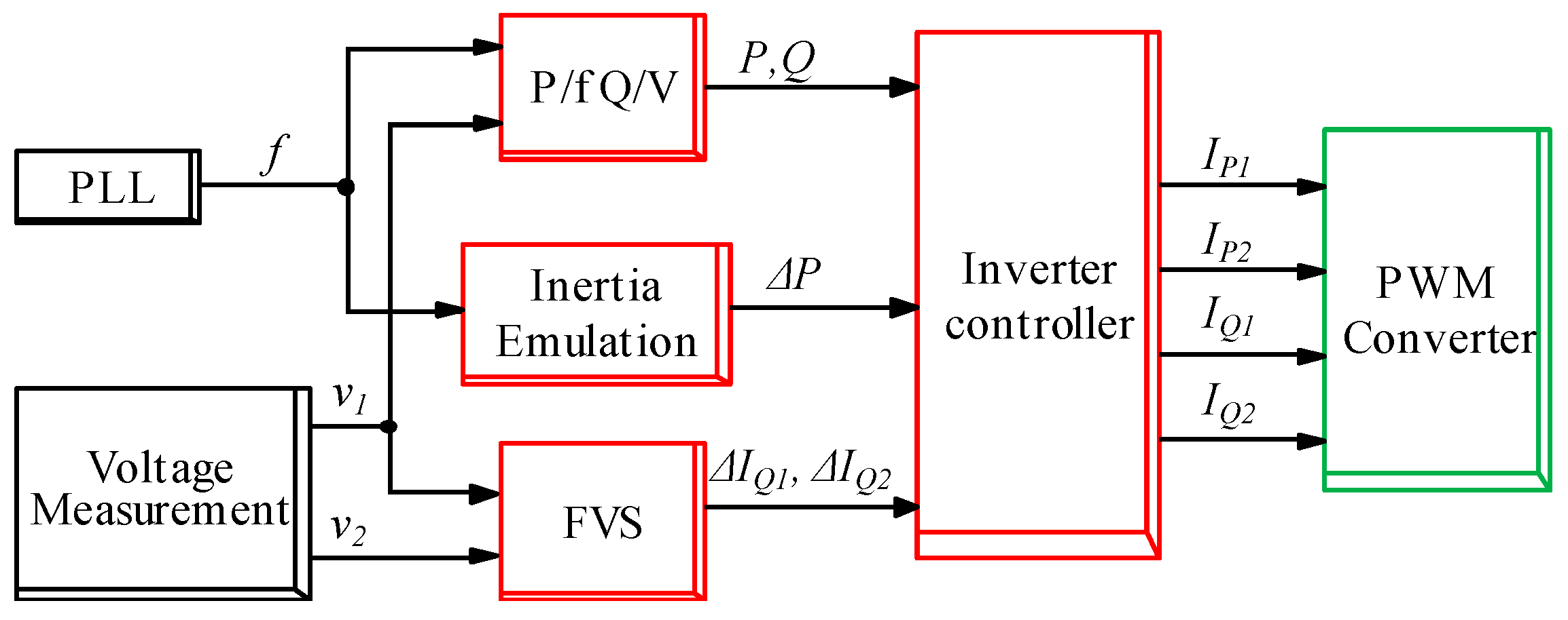
4.2. Generator Model

The component “Static Generator” represents the DG units connected to the LV network, both in the case of single plant or in the case of multiple dispersed units along the distribution feeder. The PWM electronic converter, modelled as a current-controlled device, has a 100 kVA size. Its active and reactive power injections are controlled depending on both the study case (in terms of initial conditions, as discussed in the following section) and the contribution of stabilizing functions.
A dedicated control model has been developed to accurately reproduce in the simulation software environment the behaviour of the inverter, according to present and proposed regulating capabilities. All of the four previously-illustrated stabilizing functions have been implemented and they can be individually activated. A macro block-diagram of the control scheme for the static generator is reported in Figure 8, in which blocks “PLL”, “Voltage Measurement”, and “PWM Converter” are physical elements installed in the network, whereas the others are logic controllers. On the left, the frequency measurement block “PLL” makes available the frequency at the node “AC Control-bus”, whereas the “Voltage Measurement” block evaluates the positive and negative sequence voltages at the same point (v1, v2). The obtained measures are elaborated by the red blocks in which the mathematical formulations of the regulating functions are implemented making use of the DIgSILENT simulation language (DSL): (i) the block “P/f Q/V” defines the reference active and reactive power as a function of voltage, frequency, and P-Q steady-state set-points, according to Italian standards; (ii) “Inertia Emulation” evaluates the additional active power as function of the frequency time derivative; and (iii) the “FVS” element defines the positive and negative sequence currents for the dynamic voltage support. The block “Inverter controller” converts power and current input in terms of the reference current signals (direct and quadrature components, subscripts P and Q, respectively, evaluated at the positive and the negative sequences, subscripts 1 and 2) to drive the inverter (“PWM Converter”). The DG capability constraints are evaluated by the inverter controller and the already defined functions (P/f and Q/V) take priority over the proposed ones (inertia emulation and the FVS).
The inertia emulation contribution is characterized through the definition of three parameters, as described above: (i) the proportional constant Kd derived from the equivalent desired inertia constant H (in this work, H = 0.5 s, Kd = 0.0032 [p.u.]); (ii) the time constant Td for the low pass filter (Td = 0.5 s); and (iii) the percent maximum inertia contributions (referring to the DG converter rated power, ΔPSI,n = −5%, ΔPSI,p = 5%). For the FVS function it is here assumed k = 3 to the proportional constant of Equations (1) and (2), according to the MV grid standard [2]. Current injections from Q/V and FVS are limited by the inverter capability, considering a maximum current injection during transients equal to the 150% of the inverter rated value.
The IPS imposed on the DG unit is represented through a dedicated model which monitors the network parameters at the node “AC Control-bus”. The measured values of frequency and voltage are compared with the connection rule requirements [5] to define the DG disconnection.

5. Results

Two types of network events have been analysed to assess the contribution of static generators to voltage and frequency stability. The first simulation type focuses on the unintentional LV islanding formation due to the disconnection of the LV side of the transformer, to highlight the alterations of the network parameters and their consequences on loss-of-main protection operation. The second simulation type analyses the effects of stabilizing functions applied to DG units, in terms of voltage variations during a three-phase short circuit on the MV side of the distribution transformer. The P/f and Q/V contributions are clearly appreciable in both cases, whereas inertia emulation and FVS have been introduced separately in the first and second case respectively (considering their effects as a consequence of frequency and voltage perturbations). In both cases, the permissive thresholds for the frequency relay are adopted.

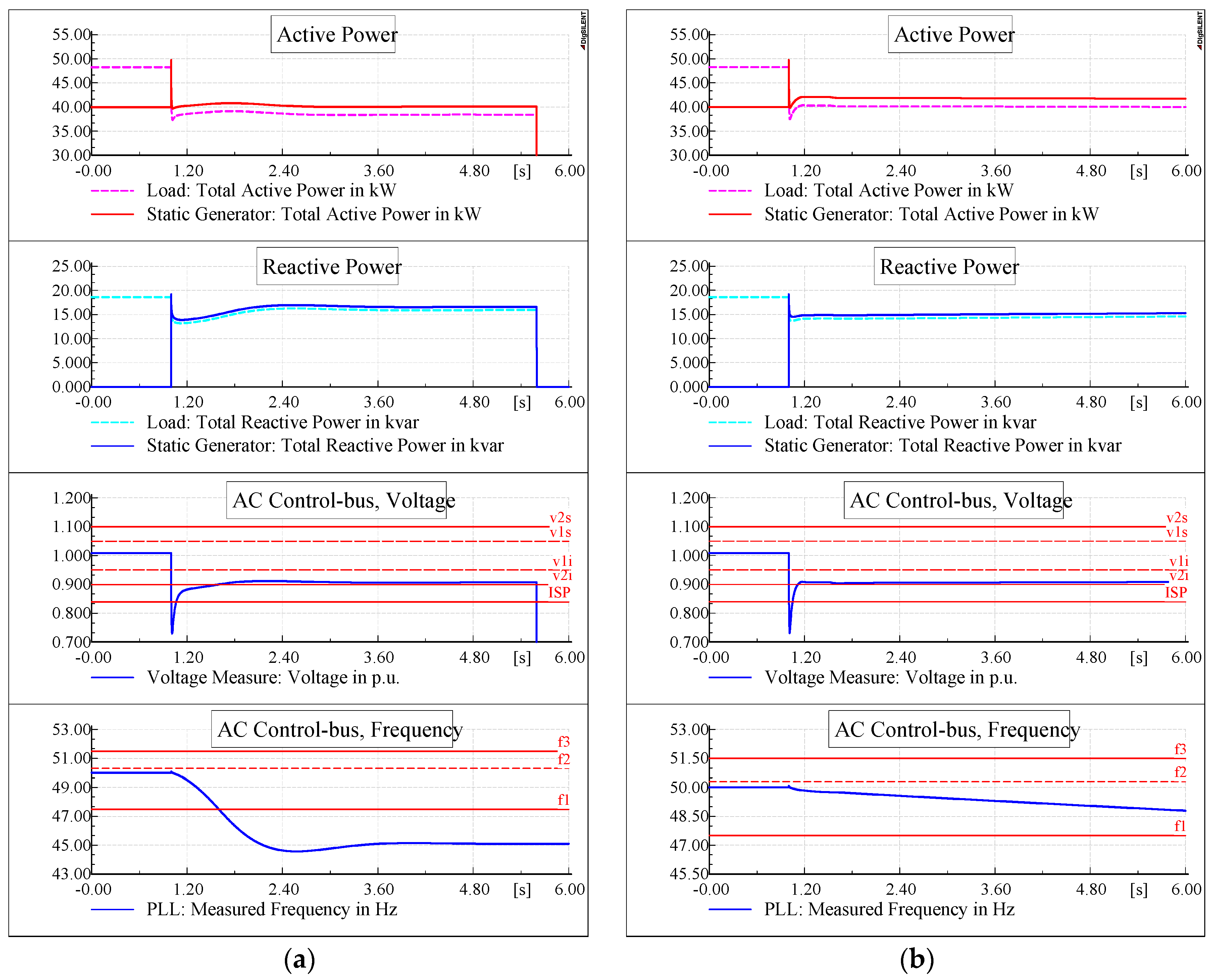
5.1. Islanded Network Stability

The islanding condition is created by opening the switch downstream of the transformer at the time instant t = 1 s. As a consequence, the LV portion of the network remains energized by the static generator.
Having disconnected the capacitor bank (CB) from the network, different values of the generator active power set-point have been examined to identify distinct contributions, as reported in Table 2: (i) active power generation lower than the load consumption (80%); (ii) active power generation equal to the load consumption (in this configuration the lowest frequency perturbations are expected [18]); and (iii) active power generation higher than the load consumption (120%). The DG reactive power set-point is equal to zero in steady-state conditions according to [5]. For each case, three configurations have been taken into account: (a) absence of power regulations (which means DG operating with fixed active and reactive set-points); (b) activation of P/f and Q/V; and (c) activation of the synthetic inertia in addition to P/f and Q/V regulations.
For each configuration, Table 2 reports the simulation results specifying whether the IPS correctly operates extinguishing the undesired islanded phenomenon (YES) or not (NO). In the simulations, the IPS is considered ineffective if the islanded condition is not identified (and consequently de-energized) by disconnecting the DG in less than five seconds from the islanding formation.
The results analysis clearly shows that the on-board regulating functions, which have been designed for grid-connected DG operation, significantly contribute to maintain uncontrolled islanding conditions in the separated network portion. In detail, considering configurations ii.a, ii.b and ii.c, in which an active power equilibrium between generation and load exists at the time of islanding formation (Psetpoint = Pload), without regulations the IPS correctly intervenes as a consequence of a rapid frequency rise due, in part, to the reactive power imbalance QloadQsetpoint. It is relevant to note that activation of the sole stabilization functions presently required by the Italian standards (P/f and Q/V) is sufficient for inhibiting the loss-of-main protection, thus enabling the islanding operation.
Differently, taking into account configurations i.a, i.b, and i.c (where Psetpoint < Pload), the active power surplus supplied by the inertia emulation is sufficient to cause a stable islanding phenomenon for a non-negligible duration (case i.c). Figure 9a, referring to the scenario i.b, reports the case of the active power deficit in the LV network at the islanding formation, where the synthetic inertia is not activated on the DGs. Active power, reactive power, voltage, and frequency profiles during the transient are illustrated. Plain lines represent the inverter quantities, whereas dotted lines represent the load ones. Symbols v1s, v2s, v1i, and v2i refer to the Q/V activation thresholds, whereas f1, f2, and f3 refer to the IPS thresholds 51.5, 50.3, and 47.5 Hz, respectively. It is clearly visible that, following the switch opening, the voltage rapidly drops, but is quickly restored and maintained within acceptable levels by the Q/V regulation (as witnessed by the plain blue line in the second diagram from the top), whereas the frequency decreases below the 47.5 Hz threshold and the IPS correctly intervenes through the under frequency relay four seconds later than the under-frequency threshold violation (island is de-energized at t = 5.59 s).
Figure 9b illustrates the behaviour of active and reactive power, voltage, and frequency in case the synthetic inertia emulation is activated (case i.c). After the islanding formation and the consequent voltage perturbation, voltage is quickly restored and maintained in the admitted region (0.85–1.15 p.u.) by the Q/V regulation, similarly to the previous case i.b shown in Figure 9a. In the present case, however, the active power injected by the synthetic inertia regulating function has a considerable smoothing effect on the frequency drop. Consequently, the under-frequency relay of the IPS cannot detect the islanding event, allowing a stable operation of the network portion disconnected by the main grid for a non-negligible duration (longer than five seconds).
In the second and third scenarios (Psetpoint = Pload and Psetpoint > Pload, respectively), the results are similar, i.e., the activation of the sole P/f and Q/V regulations (case ii.b and iii.b) is sufficient to inhibit the IPS action even if the inertia emulation is not activated. The islanded portion of network is able to reach a stable operating condition since the generated active power is reduced according to the pre-set statism of the P/f curve.
It is worth assessing the role of reactive compensation devices connected to the LV network (e.g., capacitor banks installed by end-user to avoid or reduce bill penalties [45,46]). For this purpose, a capacitor bank with 20 kvar rated power is introduced (as shown in Figure 7) to fully compensate the load reactive absorption (case “CB” in Table 2). Even if regulations are deactivated, the presence of the reactive compensator contributes supporting a stable islanding steady-state regime in case of both Psetpoint < Pload and Psetpoint = Pload (scenarios i.a and ii.a, respectively). In the first case the capacitor bank involves an admitted voltage drop that implies an active power equilibrium and frequency stability (remembering that Pload depends on the voltage level at the connection node). In the scenario ii.a, the capacitor bank dramatically reduces the reactive power load-generation unbalance limiting the voltage perturbation caused by the island separation.
Table 3 generalizes the results previously reported in Table 2. For each configuration in terms of activated stabilizing functions, and considering different load power factors (corrected by the reactive power compensator), the range of DG active power set-point Psetpoint involving an incorrect operation of the IPS is reported. It is clearly demonstrated how the activation of stabilizing functions, useful in steady-state operating conditions, enlarges the range of possible conditions in which an unintentional island could be supplied by local DGs for a non-negligible duration. The range enlargement is particularly significant in the case of generation surplus, i.e., the P/f action has a great contribution on islanding stabilization in case the IPS adopts the permissive thresholds on the frequency relay.
Furthermore, a detrimental effect caused by reactive power compensators is appreciable. Generally speaking, compensation devices modify the range of DG active power involving unintentional islanding conditions. In particular, a stable islanded operation could be reached by the network even if no stabilizing functions are activated on the DG unit.

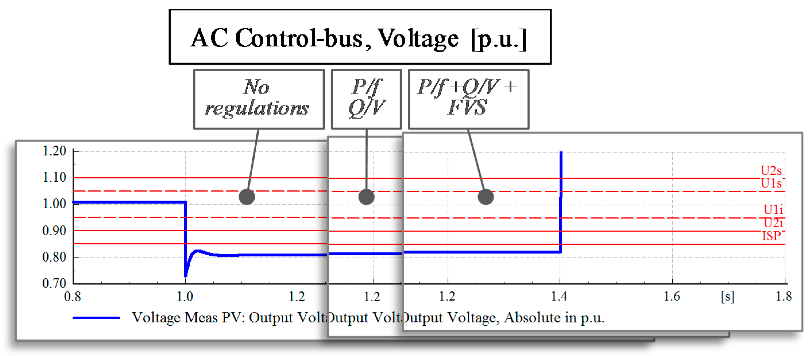
5.2. Voltage Levels during Faults

In this case, a three-phase short circuit event is simulated at the MV side of the distribution transformer at t = 1 s, with a resistive fault impedance 1.3 Ω. As a consequence, a symmetrical voltage drop is experienced by the entire LV network. All of the devices, before the IPS action, are still energized by both the external MV grid and the LV static generator. In this way, the frequency is maintained almost unchanged and the inertia emulation becomes ineffective.
Three conditions of active power imbalance have been tested, as detailed in Table 4, with the aim to verify possible different generator contributions to the network stability. For each condition, three scenarios with different activated functions have been considered: (a) no regulations; (b) activation of the sole P/f and Q/V functions; and (c) FVS is added to P/f and Q/V actions. The load is unchanged with respect to the previous study case and the capacitor bank is disconnected.
Table 4 reveals that the IPS operation is always well-timed: no power regulation is adequate to correct the voltage drop maintaining it in the admitted region. In addition, no appreciable differences appear modifying the active power injected by the inverter (Psetpoint) because, in any case, the external grid compensates the imbalance between generation and load.
Figure 10 illustrates the contribution of the stabilizing functions in terms of voltage drop reduction during the fault, considering Psetpoint equal to 50 kW and comparing the voltages at the node “AC Control-bus” as measured in the different scenarios. The voltage profiles obtained with the sole Q/V and adding FVS are superimposed to the image referred to the base case, without stabilizing regulations (on the left). The voltage is equal to 1 p.u. before the event and drops under 0.85 p.u. during the short circuit. In the central frame, the activation of Q/V lightly supports the voltage raise. On the right, the combination of Q/V and FVS further contributes to the voltage restoring but not enough to ensure a stable operation within the allowed range, so the IPS correctly trips at t = 1.40 s (final voltage step, in coherence with Figure 4). However, the stabilizing function activation could result in a more critical detection of anomalous conditions, taking into account the measurement error. In general, different results can be obtained depending on the fault impedance.

6. Conclusions

Up until now dispersed generators have been traditionally connected to LV distribution grids without requiring any stabilizing behaviour to support network contingencies. In case of low penetration of local generators, passive loss-of-main protections were able to efficiently identify potentially dangerous conditions and safely disconnect the generation. Only a perfect reactive compensation of the load absorption would give rise to a potential risk of unintentional islanding.
Subsequently, since the dispersed generation has increased its diffusion in distribution systems, active end-users are required to participate in network stability. In particular, advanced functions have been imposed to local static generating units, which may easily be accounted for by suitably modifying the electronic converter controller. In this way, small-scale generators contribute to minimizing over-frequency perturbations by modulating active power, have a role in sustaining voltage along the feeder by exchanging reactive power, and avoid undesired disconnections acting on the IPS thresholds (e.g., implementing the FVRT). In addition, further stabilizing functions are under study, such as voltage support strategies and synthetic inertia.
This work demonstrates how the adoption of stabilizing regulations on dispersed generators, even if a better behaviour in the case of main network events is assured, may have potential negative effects in terms of islanding detection and, consequently, safety issues. Taking into account the present grid code requirements, simulations show that, in several network operating conditions, portions of the LV grid could be energized by dispersed units for a non-negligible duration. In other words, presently-required IPSs may be unable to identify the islanding condition, since the frequency/voltage perturbations during the island formation are reduced by stabilizing functions. It is demonstrated that raising the DG penetration, introducing further stabilizing functions (such as voltage support and synthetic inertia), and connecting compensating units to regulate the end-users power factor, may dramatically increase the risk of failure of present loss-of-main protections.

Author Contributions

Fabio Bignucolo, Alberto Cerretti and Roberto Turri conceived the project; Fabio Bignucolo, Massimiliano Coppo and Andrea Savio developed the dynamic models in the simulation software environment and performed the dynamic analyses. All authors wrote, reviewed and approved the manuscript.

Conflicts of Interest

The authors declare no conflict of interest.

References

  1. European Committee for Electrotechnical Standardization. Requirements for Generating Plants to Be Connected in Parallel with Distribution Networks—Part 1: Connection to a LV Distribution Network above 16 A; Technical Specification CENELEC TS 50549-1; European Committee for Electrotechnical Standardization (CENELEC): Brussels, Belgium, 2015. [Google Scholar]
  2. European Committee for Electrotechnical Standardization. Requirements for Generating Plants to Be Connected in Parallel with Distribution Networks–Part 2: Connection to a MV Distribution System; Technical Specification CENELEC TS 50549-2; CENELEC: Brussels, Belgium, 2015. [Google Scholar]
  3. European Committee for Electrotechnical Standardization. Requirements for Micro-Generating Plants to Be Connected in Parallel with Public Low-Voltage Distribution Networks; European Standard CENELEC EN 50438; CENELEC: Brussels, Belgium, 2013. [Google Scholar]
  4. Comitato Elettrotecnico Italiano. Reference Technical Rules for the Connection of Active and Passive Consumers to the HV and MV Electrical Networks of Distribution Company; CEI 0-16; CEI: Milan, Italy, 2016. [Google Scholar]
  5. Comitato Elettrotecnico Italiano. Reference Technical Rules for the Connection of Active and Passive Users to the LV Electrical Utilities; CEI 0-21; CEI: Milan, Italy, 2016. [Google Scholar]
  6. Bignucolo, F.; Caldon, R.; Prandoni, V. Radial MV networks voltage regulation with distribution management system coordinated controller. Electr. Power Syst. Res. 2008, 78, 634–645. [Google Scholar] [CrossRef]
  7. Bignucolo, F.; Caldon, R.; Carradore, L.; Sacco, A.; Turri, R. Role of storage systems and market based ancillary services in active distribution networks management. In Proceedings of the 43rd International Conference on Large High Voltage Electric Systems (CIGRE), Paris, France, 22–27 August 2010; p. 9.
  8. Kang, H.-K.; Chung, I.-Y.; Moon, S.-I. Voltage control method using distributed generators based on a multi-agent system. Energies 2015, 8, 14009–14025. [Google Scholar] [CrossRef]
  9. Yang, J.-S.; Choi, J.-Y.; An, G.-H.; Choi, Y.-J.; Kim, M.-H.; Won, D.-J. Optimal scheduling and real-time state-of-charge management of energy storage system for frequency regulation. Energies 2016, 9, 1010. [Google Scholar] [CrossRef]
  10. Hou, X.; Sun, Y.; Yuan, W.; Han, H.; Zhong, C.; Guerrero, J.M. Conventional P-ω/Q-V droop control in highly resistive line of low-voltage converter-based ac microgrid. Energies 2016, 9, 943. [Google Scholar] [CrossRef]
  11. Vandoorn, T.L.; Renders, B.; Degroote, L.; Meersman, B.; Vandevelde, L. Active load control in islanded microgrids based on the grid voltage. IEEE Trans. Smart Grid 2011, 2, 139–151. [Google Scholar] [CrossRef]
  12. Latif, A.; Gawlik, W.; Palensky, P. Quantification and mitigation of unfairness in active power curtailment of rooftop photovoltaic systems using sensitivity based coordinated control. Energies 2016, 9, 436. [Google Scholar] [CrossRef]
  13. Blazic, B.; Papic, I. Voltage profile support in distribution networks—Influence of the network R/X ratio. In Proceedings of the 13th Power Electronics and Motion Control (EPE-PEMC) Conference, Poznan, Poland, 1–3 September 2008; pp. 2510–2515.
  14. Caldon, R.; Coppo, M.; Turri, R. Voltage unbalance compensation in LV networks with inverter interfaced distributed energy resources. In Proceedings of the IEEE International Energy Conference and Exhibition (ENERGYCON), Florence, Italy, 9–12 September 2012; pp. 527–532.
  15. Caldon, R.; Coppo, M.; Turri, R. Coordinated voltage control in MV and LV distribution networks with inverter-interfaced users. In Proceedings of the IEEE Grenoble Conference (PowerTech), Grenoble, France, 16–20 June 2013.
  16. Bignucolo, F.; Bertoluzzo, M.; Fontana, C. Applications of the solid state transformer concept in the electrical power system. In Proceedings of the International Annual Conference (AEIT), Napoli, Italy, 14–16 October 2015.
  17. Savio, A.; Bignucolo, F.; Caldon, R. Contribution of MV static distributed generation to voltage unbalance mitigation. In Proceedings of the AEIT International Annual Conference, Capri, Italy, 5–7 October 2016.
  18. Bignucolo, F.; Caldon, R.; Frigo, M.; Morini, A.; Pitto, A.; Silvestro, F. Impact of distributed generation on network security: Effects on loss-of-main protection reliability. In Proceedings of the Universities Power Engineering Conference (UPEC), Padova, Italy, 1–4 September 2008.
  19. Caldon, R.; Coppo, M.; Sgarbossa, R.; Turri, R. Risk of unintentional islanding in LV distribution networks with inverter-based DGs. In Proceedings of the 48th International Power Engineering Conference, Dublin, UK, 2–5 September 2013; pp. 1–6.
  20. Sgarbossa, R.; Lissandron, S.; Mattavelli, P.; Turri, R.; Cerretti, A. Analysis of ΔP-ΔQ area of uncontrolled islanding in low voltage grids with PV generators. IEEE Trans. Ind. Appl. 2016, 52, 2387–2396. [Google Scholar] [CrossRef]
  21. Cerretti, A.; D’Orazio, L.; Pezzato, C.; Sapienza, G.; Valvo, G.; Camalleri, N.; Mattavelli, P.; Sgarbossa, R.; Turri, R.; De Berardinis, E. Uncontrolled islanding operations of MV/LV active distribution networks. In Proceedings of the 2015 IEEE Eindhoven PowerTech, Eindhoven, The Netherlands, 29 June–2 July 2015; pp. 1–6.
  22. Amadei, F.; Cerretti, A.; Coppo, M.; Mattavelli, P.; Sgarbossa, R.; Turri, R. Temporary islanding operations of MV/LV active distribution networks under fault conditions. In Proceedings of the 49th International Universities Power Engineering Conference, Cluj-Napoca, Romania, 2–5 September 2014; pp. 1–6.
  23. Bignucolo, F.; Savio, A.; Turri, R.; Cerretti, A. Undesired islanding of MV networks sustained by LV dispersed generators compliant with present grid code requirements. In Proceedings of the 51st International Universities UPEC, Coimbra, Portugal, 6–9 September 2016.
  24. Sundar, D.J.; Kumaran, M.S. A comparative review of islanding detection schemes in distributed generation systems. Int. J. Renew. Energy Res. 2015, 5, 1016–1023. [Google Scholar]
  25. Fazio, A.R.D.; Russo, M.; Valeri, S. A new protection system for islanding detection in LV distribution systems. Energies 2015, 8, 3775–3793. [Google Scholar] [CrossRef]
  26. Ahmad, A.; Rajaji, L. Anti islanding technique for grid connected residential solar inverter system. In Proceedings of the Institution of Engineering and Technology (IET) Chennai Fourth International Conference on Sustainable Energy and Intelligent Systems (SEISCON), Chennai, India, 12–14 December 2013; pp. 114–118.
  27. Cataliotti, A.; Cosentino, V.; Guaiana, S.; Di Cara, D.; Panzavecchia, N.; Tinè, G. An interface protection system with power line communication for distributed generators remote control. In Proceedings of the 2014 IEEE International Workshop on Applied Measurements for Power Systems (AMPS), Aachen, Germany, 24–26 September 2014; pp. 1–6.
  28. Bufano, V.; D’Adamo, C.; D’Orazio, L.; D’Orinzi, C. Innovative solutions to control unintentional islanding on LV network with high penetration of distributed generation. In Proceedings of the 22nd International Conference and Exhibition on Electricity Distribution (CIRED), Stockholm, Sweden, 10–13 June 2013; pp. 1–4.
  29. Bufano, V.; Camalleri, N.; Cerretti, A.; D’Adamo, C.; D’Orazio, L.; Pezzato, C.; De Berardinis, E. Risk of uncontrolled islanding on active distribution networks short term countermeasures taken by Enel Distribuzione. In Proceedings of the 23nd International Conference and Exhibition on Electricity Distribution, Lyon, France, 15–18 June 2015.
  30. Kniccic, S.; Chandra, A.; Lagacé, P.; Papic, M. Dynamic voltage support of the transmission network from distribution level. In Proceedings of the 2006 IEEE Power Engineering Society General Meeting, Montreal, QC, Canada, 18–22 June 2006.
  31. Marinopoulos, A.; Papandrea, F.; Reza, M.; Norrga, S.; Spertino, F.; Napoli, R. Grid integration aspects of large solar PV installations: LVRT capability and reactive power/voltage support requirements. In Proceedings of the 2011 IEEE Trondheim PowerTech, Trondheim, Norway, 18–19 May 2011; pp. 1–8.
  32. Lammert, G.; Heß, T.; Schmidt, M.; Schegner, P.; Braun, M. Dynamic grid support in low voltage grids-fault ride-through and reactive power/voltage support during grid disturbances. In Proceedings of the Power Systems Computation Conference (PSCC), Wroclaw, Poland, 18–22 August 2014; pp. 1–7.
  33. Camacho, A.; Castilla, M.; Miret, J.; Vasquez, J.; Alarcon-Gallo, E. Flexible voltage support control for three-phase distributed generation inverters under grid fault. IEEE Trans. Ind. Electron. 2013, 60, 1429–1441. [Google Scholar] [CrossRef]
  34. Camacho, A.; Castilla, M.; Miret, J.; Guzman, R.; Borreli, A. Reactive power control for distributed generation power plants to comply with voltage limits during grid faults. IEEE Trans. Power Electron. 2014, 29, 6224–6234. [Google Scholar] [CrossRef]
  35. Sulla, F.; Svensson, J.; Samuelsson, O. Wind turbines voltage support in weak grids. In Proceedings of the 2013 IEEE Power & Energy Society General Meeting, Vancouver, BC, Canada, 21–25 July 2013; pp. 1–5.
  36. Rahmann, C.; Jara, J.; Salles, M.B. Effects of inertia emulation in modern wind parks on isolated power systems. In Proceedings of the 2015 IEEE Power & Energy Society General Meeting, Denver, CO, USA, 26–30 July 2015; pp. 1–5.
  37. Gonzales-Longatt, F.; Chikuni, E.; Rashayi, E. Effects of the synthetic inertia from wind power on the total system inertia after a frequency disturbance. In Proceedings of the 2013 IEEE International Conference on Industrial Technology (ICIT), Cape Town, South Africa, 25–28 February 2013; pp. 826–832.
  38. Mentesidi, K.; Garde, R.; Aguado, M.; Rikos, E. Implementation of a fuzzy logic controller for virtual inertia emulation. In Proceedings of the 2015 International Symposium on Smart Electric Distribution Systems and Technologies (EDST), Vienna, Austria, 8–11 September 2015; pp. 606–611.
  39. Gavriluta, C.; Candela, I.; Rocabert, J.; Exteberria-Otadui, I.; Rodriguez, P. Storage system requirements for grid supporting PV-power plants. In Proceedings of the 2014 IEEE Energy Conversion Congress and Exposition (ECCE), Pittsburgh, PA, USA, 14–18 September 2014; pp. 5323–5330.
  40. Thiesen, H.; Jauch, C.; Gloe, A. Design of a system substituting today’s inherent inertia in the European continental synchronous area. Energies 2016, 9, 582. [Google Scholar] [CrossRef]
  41. Visconti, I.F.; Lima, D.A.; de Sousa Costa, J.M.C.; de B.C. Sobrinho, N.R. Measurement-Based load modeling using transfer functions for dynamic simulations. IEEE Trans. Power Syst. 2014, 29, 111–120. [Google Scholar]
  42. Vignesh, V.; Chakrabarti, S.; Srivastava, S.C. Power system load modelling under large and small disturbances using phasor measurement units data. IET Gener. Transm. Dis. 2015, 9, 1316–1323. [Google Scholar]
  43. Savio, A.; Bignucolo, F.; Sgarbossa, R.; Mattavelli, P.; Cerretti, A.; Turri, R. A novel measurement-based procedure for load dynamic equivalent identification. In Proceedings of the 2015 IEEE 1st International Forum on Research and Technologies for Society and Industry Leveraging a better tomorrow (RTSI), Turin, Italy, 16–18 September 2015; pp. 274–279.
  44. Milanović, J.; Matevosiyan, J.; Gaikwad, A. TB 566: Modeling and Aggregation of Loads in Flexible Power Networks —WG C4.605; Technical Report; International Council on Large Electric systems (CIGRE): Paris, France, 2014. [Google Scholar]
  45. Cocchi, L.; Cerretti, A.; Deberardinis, E.; Bignucolo, F.; Savio, A.; Sgarbossa, R. Influence of average power factor management on active distribution networks. In Proceedings of the 23nd International Conference and Exhibition on Electricity Distribution (CIRED), Lyon, France, 15–18 June 2015.
  46. Bignucolo, F.; Savio, A.; Caldon, R. Effects of average power factor management in distribution systems with dispersed generation. In Proceedings of the 2016 International Annual Conference (AEIT), Capri, Italy, 5–7 October 2016.
Figure 1. Active power regulation characteristic (P/f): activation thresholds and active power hysteresis behaviour (time duration of 300 s) to avoid frequency oscillations. The red trajectory represents the active power trend required for a distributed generator (DG) unit connected at a low voltage (LV) level in the case of frequency perturbations with a peak value between f2 and f3.
Energies 10 00156 g001
Figure 2. Reactive power regulation characteristic (Q/V): activation thresholds and maximum reactive contribution required (Q/Pr > 0 means a reactive behaviour of the DG unit equivalent to a capacitive absorption).
Energies 10 00156 g002
Figure 3. Frequency protection thresholds: restrictive and permissive thresholds can be activated according to distribution system operator (DSO) requirements (connection rules or DSO external signal).
Energies 10 00156 g003
Figure 4. Voltage protection thresholds: the under-voltage protection implements the fault voltage ride through (FVRT) function to prevent DG disconnection in the case of fast voltage variations.
Energies 10 00156 g004
Figure 5. Fast voltage support (FVS) regulating function applied to LV DGs. The dead-band range around the unperturbed condition and the value of constant k have been hypothesised in accordance with the FVS function required for medium voltage (MV) DG units [2].
Energies 10 00156 g005
Figure 6. Synthetic inertia transfer function. Frequency deviation is measured through a phase-locked loop (PLL).
Energies 10 00156 g006
Figure 7. Schematic LV network adopted as the case study.
Energies 10 00156 g007
Figure 8. Control scheme of the static generator.
Energies 10 00156 g008
Figure 9. Electrical parameters profiles with Psetpoint < Pload in configuration i.b (a) and i.c (b): P/f and Q/V are always active, with synthetic inertia off (left) and on (right).
Energies 10 00156 g009
Figure 10. Q/V and FVS contribution to voltage levels.
Energies 10 00156 g010
Table 1. P/f and Q/V parameters as defined by Italian standards for distributed generators (DGs) connected to the low voltage (LV) distribution system.
P/f Regulation CharacteristicQ/V Regulation Characteristic
f150.0 Hzv2s1.10 p.u.
f250.3 Hzv1s1.05 p.u.
f351.5 Hzv1i0.95 p.u.
v2s0.90 p.u.
q*0.4843 p.u.
Table 2. Islanding event parameters and their influence on the correct operation of the interface protection system (IPS) (YES means that the IPS correctly operates, NO means an IPS failure in identifying the islanding condition). CB: capacitor bank.
Generator PsetpointCaseP/f and Q/VSynthetic InertiaIPS Correct Action (without CB)IPS Correct Action (with CB)
40 kW
(80% of Pload)
i.aOFFOFFYESNO
i.bONOFFYESYES
i.cONONNONO
50 kW
(100% of Pload)
ii.aOFFOFFYESNO
ii.bONOFFNONO
ii.cONONNONO
60 kW
(120% of Pload)
iii.aOFFOFFYESYES
iii.bONOFFNONO
iii.cONONNONO
Table 3. Range of the generated power set-point Psetpoint involving a potential IPS failure in the case of transformer disconnection on the LV side. The detrimental effects of stabilizing functions and load reactive power compensation on the IPS operation clearly appears in terms of Psetpoint range width.
P/f and Q/VSynthetic InertiaLoad Power FactorRanges of DG Active Power Psetpoint Involving a IPS Failure, Compared with Pload
OFFOFF0.928 (no compensation)---
0.95 (3.6 kVAr)---
0.98 (9.9 kVAr)---
1.00 (20 kVAr)76%–116% of Pload
ONOFF0.928 (no compensation)82%–164% of Pload
0.95 (3.6 kVAr)82%–164% of Pload
0.98 (9.9 kVAr)84%–168% of Pload
1.00 (20 kVAr)86%–172% of Pload
ONON0.928 (no compensation)74%–186% of Pload
0.95 (3.6 kVAr)74%–86% of Pload
0.98 (9.9 kVAr)76%–188% of Pload
1.00 (20 kVAr)79%–190% of Pload
Table 4. Results obtained in the case of a three-phase short circuit on the MV side of the MV/LV transformer. In the analysed scenarios, no interactions between the FVS and the IPS operation appear, even if the voltage drop is reduced by the FVS.
Generator PsetpointP/f and Q/VFVSIPS Correct Action
40 kW
(80% of Pload)
OFFOFFYES
ONOFFYES
ONONYES
50 kW
(100% of Pload)
OFFOFFYES
ONOFFYES
ONONYES
60 kW
(120% of Pload)
OFFOFFYES
ONOFFYES
ONONYES

