Article

Development of Propulsion Inverter Control System for High-Speed Maglev based on Long Stator Linear Synchronous Motor

Korea Railroad Research Institute, Uiwang-si, Gyeonggi-do 16105, Korea
*
Author to whom correspondence should be addressed.
Energies 2017, 10(2), 170; https://doi.org/10.3390/en10020170
Submission received: 19 September 2016 / Revised: 30 December 2016 / Accepted: 20 January 2017 / Published: 3 February 2017
(This article belongs to the Special Issue Power Electronics and Power Quality)

Abstract

:
In the case of a long-stator linear drive, unlike rotative drives for which speed or position sensors are a single unit attached to the shaft, these sensors extend along the guideway. The position signals transmitted from a maglev vehicle cannot meet the need of the real-time propulsion control in the on-ground inverter power substations. In this paper the design of the propulsion inverter control system with a position estimator for driving a long-stator synchronous motor in a high-speed maglev train is proposed. The experiments have been carried out at the 150 m long guideway at the O-song test track. To investigate the performance of the position estimator, the propulsion control system with, and without, the position estimator are compared. The result confirms that the proposed strategy can meet the dynamic property needs of the propulsion inverter control system for driving long-stator linear synchronous motors.

1. Introduction

A maglev train system is a new transportation system technology that replaces the mechanical components by electronic devices and, thus, can help to overcome the technical limitations that wheels have in railway technology. In comparison with the existing wheel-on-rail systems, the maglev train system ensures high-speed operation, high safety, low pollution, and low energy loss for mass transport [1]. A long stator linear synchronous motor (LS-LSM) has the following special features as compared to a rotary-type synchronous motor: Since the LS-LSM is made through a combination of levitation magnets and the stator of propulsion motor, the magnetic flux density of the motor is determined by the weight of the vehicle, and the thrust force is affected by the phase angle and the magnitude of the stator current. Therefore, the position information of the mover is essential for the LS-LSM drive inverter [2,3,4,5].
In the case of the Transrapid maglev system, as the position signal detection system PRW (coming from the German word: polradwinkelverfahren) is mounted on the head portion and rear portion of the train and the position information flag is installed in the guideway, with the absolute position signals of the vehicle being transmitted to the propulsion system on the ground. The position information transmission method is to transmit the position signals using radio frequency at intervals of 20 ms with the use of the RS-485 communication protocol, and the transmission rate is 512 kbps. However, the vehicle position information obtained through this method does not meet the requirements of the propulsion inverter control system [6].
This paper seeks to develop a propulsion inverter control system technology for the SUMA550-1, a high-speed maglev train system based on an LS-LSM. The test vehicle driven by an LS-LSM was fabricated with one-half the length of the final target model for this project and a LS-LSM guideway of 150 m in length was constructed to test and evaluate the developed vehicle. The differences of propulsion control between a rotating motor and a linear motor are analyzed and the propulsion system with the vehicle magnetic flux position estimator is proposed in order to solve the problem of linear motors. A difference in thrust force control between the rotative motor and linear unit was analyzed, and the propulsion control system that has the vehicle flux position observer to solve the problem which may occur in the linear unit is presented.
For performance verification of the propulsion inverter control system of the SUMA550-1, the response characteristics of the current controller and speed controller, and the stability on the control system were analyzed through a simulation model to which the system parameters and propulsion controller gain parameters are applied. The control performance by the maximum torque, the characteristic of position estimator, and the speed profile was confirmed through a propulsion control experiment at the test track with 150 m in length.

2. Development of Propulsion Inverter Control System Based on Long Stator Linear Synchronous Motor

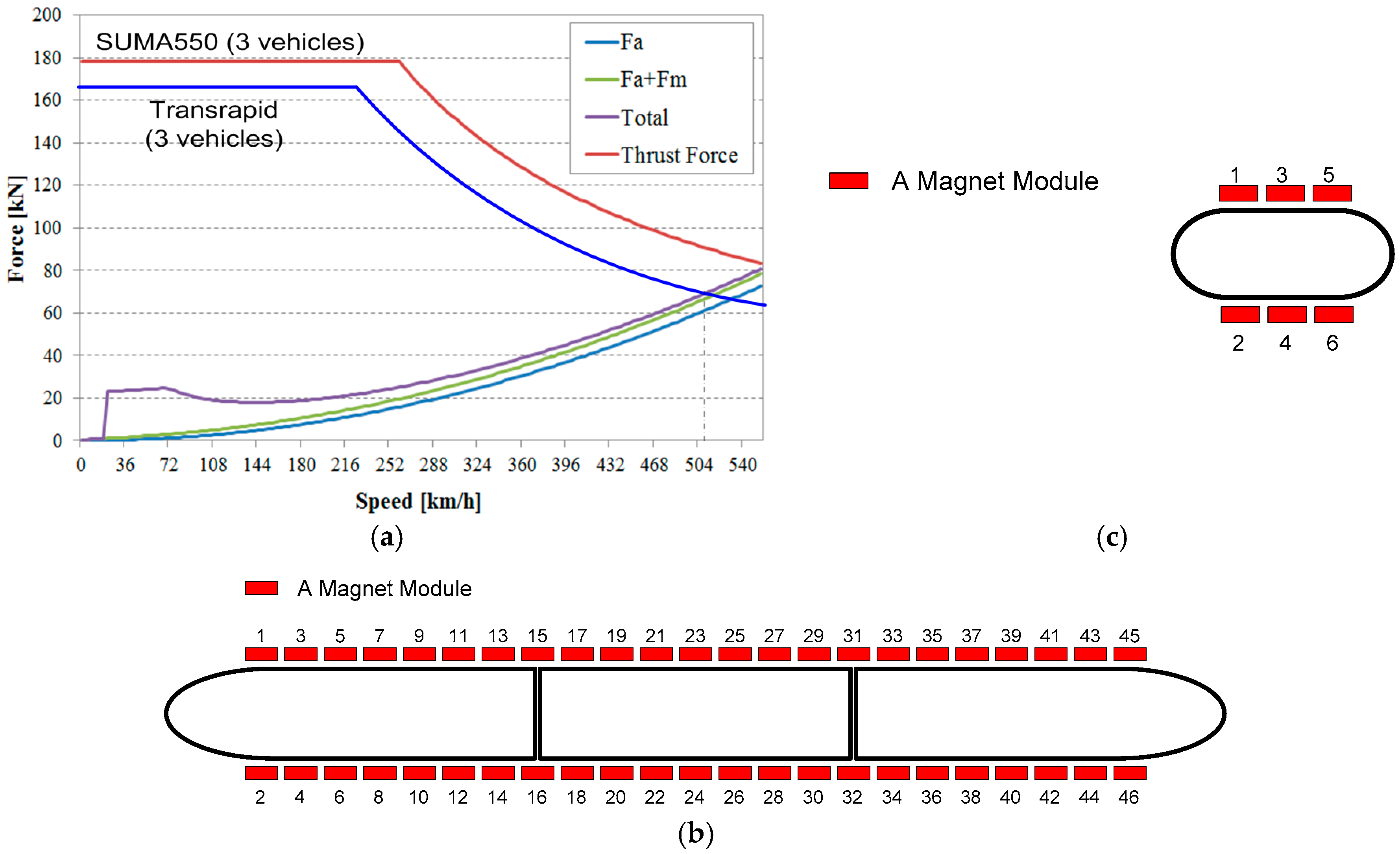
2.1. The Thrust Force Characteristics of Propulsion System for a High-Speed Maglev Train

The final model to be developed through the research and development of high-speed maglev train system is the SUMA550, whose configuration consists of three cars/one organization. The specifications of the SUMA550-1, which is the first prototype model of the high-speed maglev train system developed in this research project, are summarized in Table 1.
The entire vehicle running resistance F of the SUMA550 is expressed by the sum of all resistances to vehicle movement. Equation (1) represents the entire vehicle running resistances of high speed maglev system:
F = F a + F m + F B
where Fa is aerodynamic train running resistance; Fm is eddy current running resistance; and FB is running resistance caused by linear generator.
Each of equations for running resistance are described in Equation (2):
F a = 2.8 × v 2 × ( 0.265 × N + 0.3 ) [ N ] F m = N × ( 0.1 × v 0.5 + 0.02 × v 0.7 ) × 10 3 [ N ] F B = { 0   [ N ]   ( for   0     v     20   km / h ) N × 7.3 × 10 3   [ N ]   ( for   20     v     70   km / h ) N × ( 146 / v 0.2 ) × 10 3   [ N ]   ( for   70     v     500   km / h )
where N is the number of vehicles and v is the velocity of the vehicle.
Figure 1 shows the required thrust force curve and electromagnet arrangement of the SUMA550, and the electromagnet arrangement of the SUMA550-1.

2.2. Linear Synchronous Motor Propulsion Control System Configuration

2.2.1. Positioning System Configuration

For a propulsion system based on an LS-LSM, the phase angle error with respect to the magnetic flux angle of the vehicle levitation electromagnet (secondary side of the motor) should be maintained at less than 15° in order to maintain a high thrust force, and if it exceeds this range, the thrust force is sharply reduced to less than 80%. Since the pole pitch of LS-LSM is 240 mm, the position error between the levitation magnet on the vehicle and the LS-LSM on the guideway should be maintained within 10 mm.
The positioning system of the SUMA550-1 uses a combination of the absolute positioning system and relative positioning system to detect the absolute information of the vehicle through the absolute positioning system and the relative positioning system installed on both sides along the guideway. The absolute position information of the vehicle is detected by the position reader of the vehicle. The absolute position information detected from vehicle is transmitted to the propulsion control system on the ground via a radio communication system.

2.2.2. Design of the Propulsion Control System

The rotator flux orientated vector control has widely been used for the thrust force of propulsion systems in trains. The synchronous rotating axis in the rotator flux orientated vector control should be aligned to the flux angle of the rotator. Therefore, detecting precise position signals of the mover flux is important to the thrust force control of the synchronous motor. To this end, a resolver or an encoder is mainly utilized as a train speed and rotor position detection device, and the rotor position information with high resolution is provided to the propulsion control system [7]. However, in the propulsion system on the ground, such as high speed maglev train systems, the current position is measured in the moving vehicle, and the absolute position information of the vehicle is transmitted to the inverter on the ground in real-time. This method has three problems, as follows: First, it cannot provide the absolute position information of the 50 µs cycle required by the propulsion inverter due to the limits of the radio communication speed. Second, a failure in the radio communication makes the absolute position information update cycle variable. Third, a delay in the communication time for the absolute position information occurs when the vehicle runs at high speed.
In this paper, rotor flux oriented vector control was performed as a basic algorithm to control the thrust force of the vehicle and the flux position observer of the vehicle was utilized to align the flux of the vehicle with the moving magnetic flux of the LS-LSM. Since the propulsion inverter of the SUMA550-1 has the current control loop of a 500 µs cycle, it needs the precise magnetic flux position information of the 500 µs cycle to perform accurate phase current control in real-time. This system receives the position signal delayed by approximately 5 ms from the vehicle in a 2 ms cycle and, therefore, it requires the magnetic flux position observer that compensates the delay of the position signal [8,9,10,11]. In this paper, the closed loop full-order position observer based on the DC motor numerical model that has the position information from the vehicle as an input is proposed in order to serve the high-resolution position information required in the propulsion inverter in real-time. The detail on the design of the position observer are shown in reference [12].
θ c o m p = θ + 2 π { v × T d 1000 } d θ ^ d t = v ^ + ω n ( 2 ζ + 1 ) ( θ c o m p θ ^ ) d v ^ d t = 1 M τ ^ d + 1 M F t + ω n 2 ( 2 ζ + 1 ) ( θ c o m p θ ^ ) d τ ^ d d t = ω n 3 ( θ c o m p θ ^ )
where v represents the vehicle speed, v ^ represents a state estimate of V, Td represents the communication delay time constant, θ represents the phase angle measured in the vehicle, θcomp represents the communication delay compensation phase angle, θ ^ represents an state estimate of θ, M represents vehicle mass, Ft represents the propulsion torque of the vehicle, τd represents the disturbance torque, τ ^ d represents a state estimate of τd, ωn represents the observer natural frequency, and ζ represents the observer damping ratio.

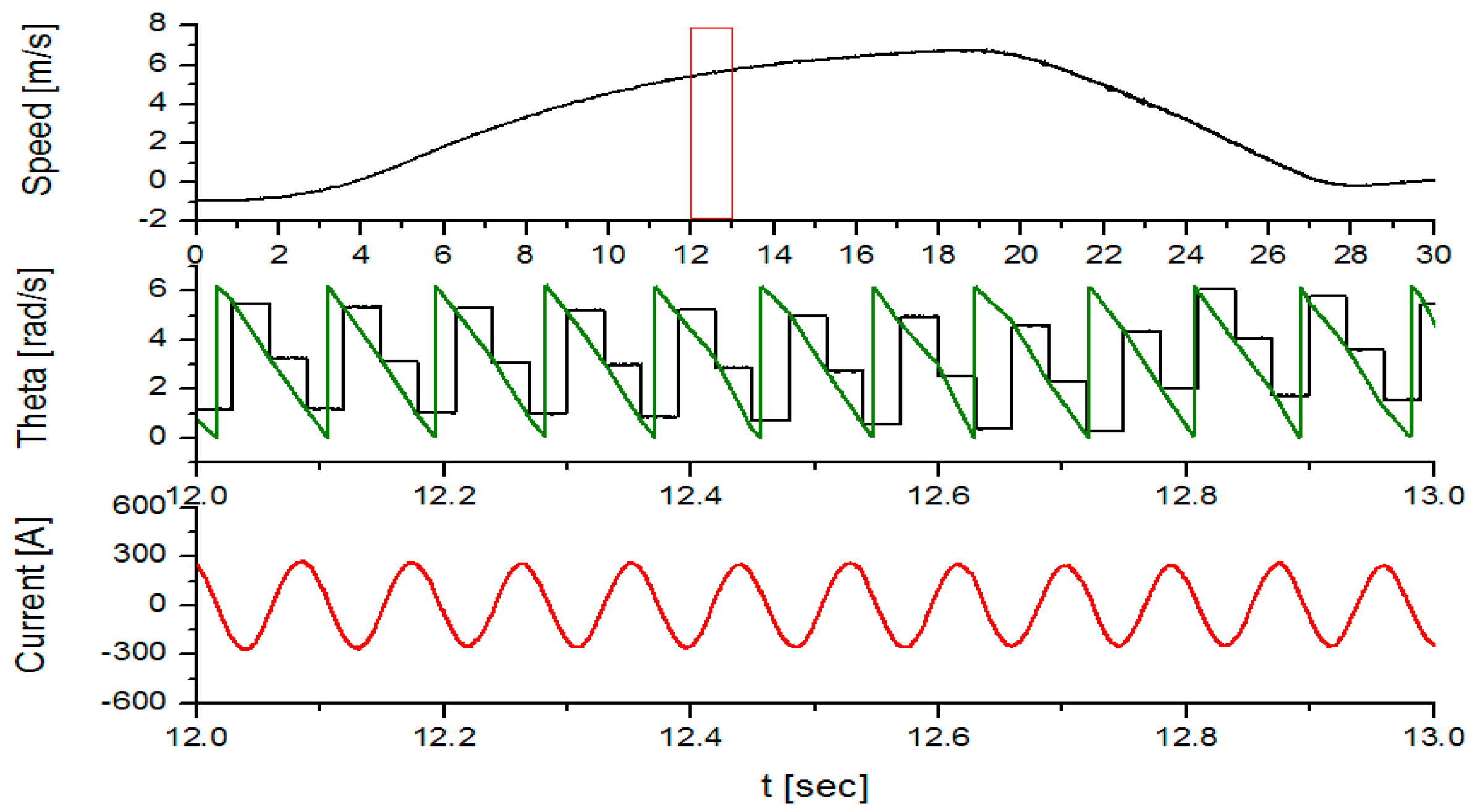
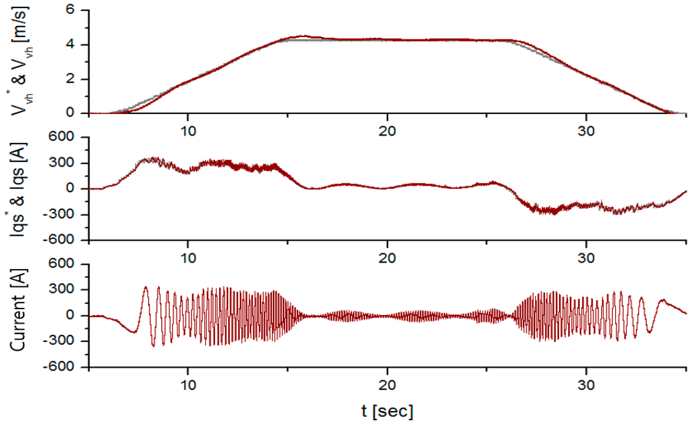
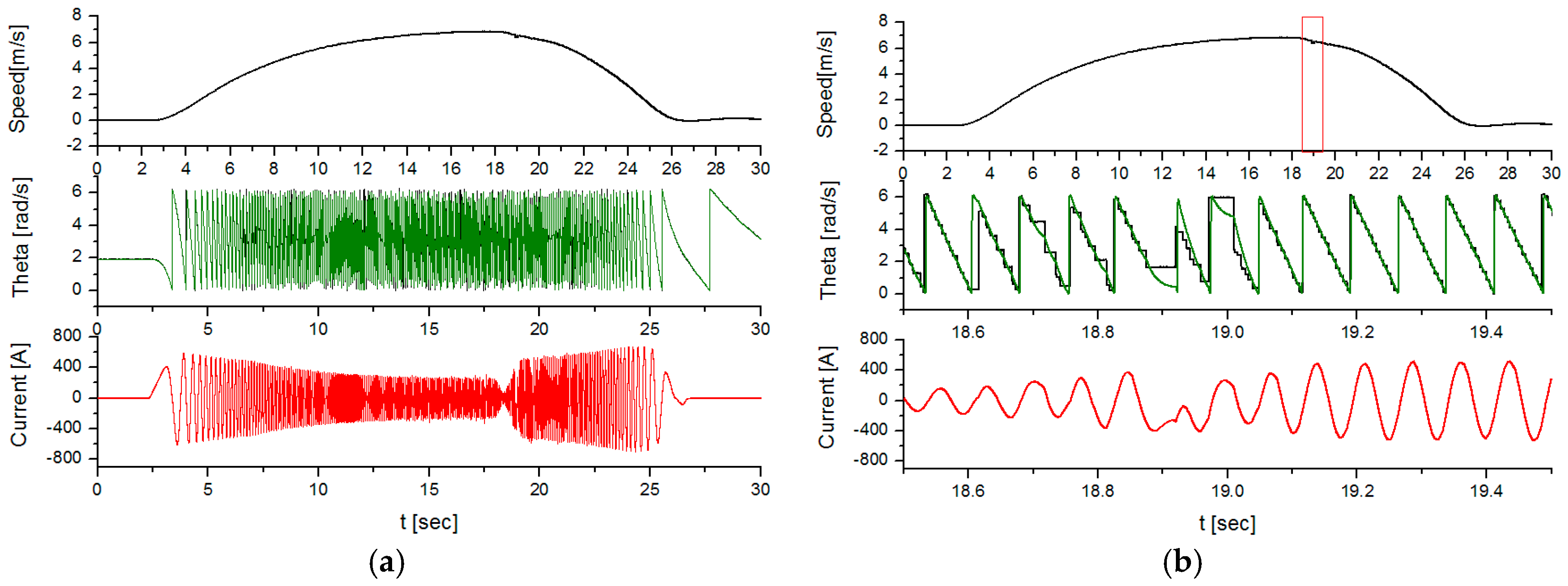
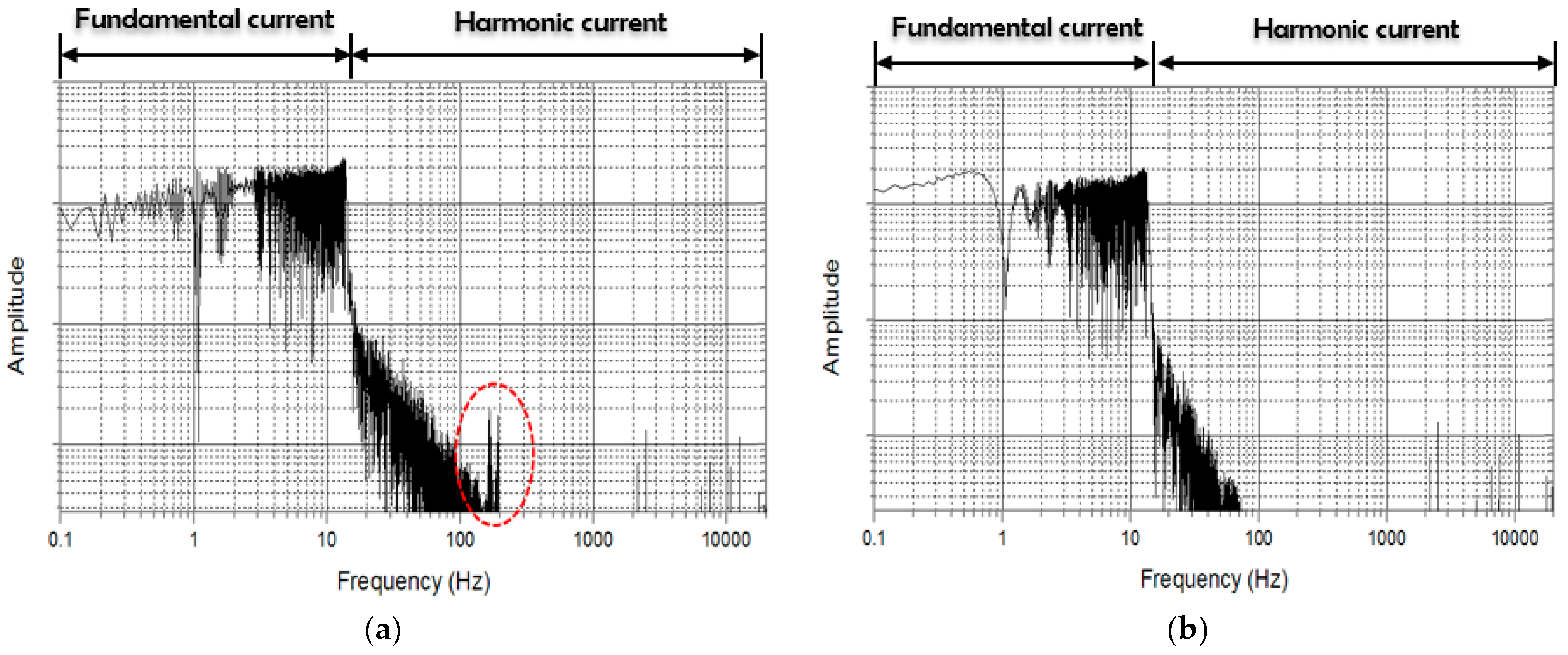
2.3. Experiments and Results Analysis

For the propulsion controller experiment of the SUMA550-1, a 150 m long guideway was constructed. An LS-LSM was installed under the both sides of the guideway, and barcodes and markers were also installed in combination with the LS-LSM. The vehicle is levitated up to 10 mm by the mover of the LS-LSM and propulsion force is generated in accordance with the phase angle and coil current of the ground LS-LSM.
The outward appearance of the SUMA550-1 is shown in Figure 2. The empty vehicle weight is 24 tons, the gross weight is 27 tons, the maximum acceleration is 1.1 m/s2, the maximum jerk is 0.5 m/s3, the maximum speed at a short-distance test line is 8 m/s, and there is no gradient of the 150 m-long guideway. The key parameters of the LS-LSM are summarized in Table 2.

2.4. Experiment Results and Analysis

For the performance verification of the propulsion control system of SUMA550-1, the maximum thrust force experiment, performance test of the position estimator, and automatic operation test by the speed profile were conducted in the test track. As described in Section 2.1, since the maximum thrust force of the SUMA550 generated by 46 magnet modules is 180 kN, the maximum design thrust force of the SUMA550-1 equipped with six magnet modules is 23.49 kN.
Figure 3 shows the maximum thrust force by applying the rated current I q s = 500 [ A ] to the LS-LSM, and it is 24.88 kN, which is slightly more than the design value. This is because as the mover magnetic flux of the LS-LSM increases, the thrust force slightly exceeds the maximum design value under the full weight condition of the vehicle.
Figure 4 and Figure 5 show the experimental result waveforms when the vehicle is operated manually at speeds of up to 7 m/s. Figure 4a shows the results of the experiment performed by applying the absolute position signals received from the vehicle, and each waveform represents the speed, vehicle flux phase angle and estimated phase angle, and phase-U current of the LS-LSM from the top. In order to analyze the distortion of the current by the discontinuous signals of the absolute position signal and the subsequent current distortion, the expansion results of the 18.5–19.5 s section are represented in Figure 4b. Figure 4 shows that there is no problem in the overall operation of the propulsion control system to which the absolute position signal is applied, but the distortion of the phase-U current of the LS-LSM stands out due to the discontinuous signal of the absolute position signal as shown in Figure 4b. This current distortion can lead to the decrease in the thrust force of the propulsion control system, instability of the communication system by the harmonic current, and increased loss of the power converter system.
Figure 5a shows the results of experiment performed by applying the vehicle position estimator of the propulsion control system, and each waveform represents the speed, vehicle flux phase angle and estimated phase angle, and phase-U current of the LS-LSM from the top. In order to analyze the discontinuous signal of the absolute position and the subsequent performance of the position estimator, the expansion results of the 18.5–19.5 s section were represented in Figure 5b.
Figure 5 shows that the propulsion control system to which the vehicle position estimator is applied is generally stable, and the phase angle of the vehicle position estimator is linearly estimated with respect to the discontinuous signal of the absolute position as shown in Figure 5b.
The deviating behavior is shown in Figure 4 and Figure 5 when the ground false position packets are received. This is because the position estimator cannot distinguish whether the absolute position information received from the vehicle is right or not. Thus, the position estimator tries to follow the wrong information.
Nevertheless, this suggests that the phase-U current of the LS-LSM maintains a sine wave with the output current controlled by the linear phase angle.
Figure 6 shows the fast fourier transform (FFT) analysis results of the current distortion depending on the presence of the vehicle position estimator in the entire running section. Figure 6a shows the FFT analysis results on the phase-U current in the case where the vehicle position estimator is not applied, and Figure 6b shows the FFT analysis results on the phase-U current of the LS-LSM in case the vehicle position estimator is applied. The comparison of the results revealed that the application of the vehicle position estimator contributed to improving the running current harmonic wave, as well as the running current fundamental wave, and the improvement rate was particularly high in the 100–200 Hz sections among running current harmonic components.
Figure 7 represents the vehicle position estimation capability in the position information update cycle of 30 ms, which is 15 times later than the current position information update cycle of 2 ms. In order to identify the characteristics of the vehicle position estimator in case the absolute position information is transmitted from the vehicle in a 30 ms cycle, which is the same as that of the Transrapid. The results of Figure 7 confirmed that the phase angle of the vehicle position estimator is linearly estimated even in the position information update information of two to three times per cycle within the propulsion current and, therefore, the output current appears sinusoidal.
The operation parameters for generation of the speed profile were entered to analyze the performance of the automatic operation. The set operation parameters include the constant operation time of 2 s, maximum jerk limit of 0.5 m/s3, maximum acceleration of 0.5 m/s2, deceleration of 0.5 m/s2, and maximum speed of 4.2 m/s, and the generated speed profile and automatic operation test results are shown in Figure 8.
The experimental results showed that the speed tracking according to the speed profile is made smoothly when the q-axis components of stator current iqs is tracked without error with respect to the q-axis components of the stator reference current iqs*. In addition, the command value of the actual travel distance and the actual travel distance were calculated by integrating the command velocity and vehicle speed, respectively, in order to obtain the error rate of the automatic operation. According to the calculation results, the travel distance by the speed command profile is 84.75 m, the actual travel distance is 85.22 m and, therefore, the error rate of the travel distance is about 0.52%, if converted into the error rate of the automatic operation.

3. Conclusions

This paper aims to develop the propulsion control system technology for a high-speed maglev train system based on an LS-LSM. To this end, a test vehicle was fabricated with one-half the length of the final model, and a 150 m long LSM guideway was constructed to conduct the test and evaluation of the developed vehicle. The vehicle flux position observer was designed to analyze the difference in thrust force control between the rotating machine and the linear machine and, thus, to solve the problem that may occur in the liner machine. In addition, the characteristics of the current controller and speed controller were analyzed to design the propulsion controller of the LS-LSM.
For verification of the propulsion control performance, experiments on the automatic operation according to the speed profile and manual operation, and a comparison of the propulsion power quality enhancement on the position observer and torque required by the vehicle were performed, and the results confirmed that the design objectives were archived. For future work, a system for position detection within 5 mm, even at the maximum speed of 550 km/h, is planned to be developed for high-speed operation.

Acknowledgments

This research was supported by a grant from Research and Development Program of the Korea Railroad Research Institute, republic of Korea.

Author Contributions

Jeong-Min Jo designed the propulsion system and programmed the algorithms. Jin-Ho Lee designed the positioning system. Young-Jae Han organized the paper. Chang-Young Lee designed the LS-LSM. Kwan-Sup Lee helped to respond to the comments and revise this paper. All authors contributed to the writing of the manuscript, and approved the final manuscript.

Conflicts of Interest

The authors declare no conflict of interest.

References

  1. Sadrnia, M.A.; Jafari, A.H. Robust control design for maglev train with parametric uncertainties using μ–systhesis. In Proceedings of the World Congress on Engineering 2007, London, UK, 2–4 July 2007.
  2. Leidhold, R.; Mutshler, P. Speed sensorless control of a long-stator linear synchronous motor arranged in multiple segments. IEEE Trans. Ind. Electr. 2008, 54, 3246–3254. [Google Scholar] [CrossRef]
  3. Qian, C.; Han, Z. Research on absolute positioning system for high-speed maglev train. In Proceedings of the 2007 IEEE International Conference on Mechatronics and Automation, Takamatsu, Japan, 5–8 August 2007.
  4. Wu, X.M. Maglev Train; Science and Technology Press: Shanghai, China, 2003. [Google Scholar]
  5. Yang, S.; Ke, S. Performance evaluation of a velocity observer for accurate velocity estimation of servo motor drives. IEEE Trans. Ind. Appl. 2000, 36, 98–104. [Google Scholar] [CrossRef]
  6. Qian, C.; Wei, R.; Wang, X.; Ge, Q.; Li, Y. Analysis the Position signal problem in propulsion system with long stator synchronous motor. In Proceedings of the Maglev 2011 Conference, Daejeon, Korea, 10–13 October 2011.
  7. Su, G.; McKeever, J.W.; Samons, L.S. Modular PM motor drives for automotive traction applications. In Proceedings of the 27th Annual Conference of the IEEE Industrial Electronics Society, Denver, CO, USA, 29 Novermber–2 December 2001.
  8. Bado, A.; Bologani, S.; Zigliotto, M. Effective estimation of speed and rotor position of a PM synchronous motor drive by a Kalman filtering technique. In Proceedings of the 23rd Annual IEEE Power Electronics Specialists Conference, Toledo, Spain, 29 June–3 July 1992.
  9. Zhu, G.; Kaddouri, A.; Dessiant, L.; Akhrif, O. A nonlinear state observer for the sensorless control of a permanent-magnet AC machine. IEEE Trans. Ind. Electr. 2001, 48, 1098–1108. [Google Scholar]
  10. Hamada, D.; Uchida, K.; Yusivar, L.F.; Wakeo, S.; Onuki, T. Sensorless control of PMSM using a linear reduced order observer including disturbance torque estimation. In Proceedings of the 8th European Conference on Power Electronics and Applications, Lausanne, Switzerland, 7–9 September 1999.
  11. Bhangu, B.; Williams, C.; Bingham, C.M.; Coles, J. EKFs and other nonlinear state-estimation techniques for sensorless control of automotive PMSMs. In Proceedings of the Speedam Conference 2002, Ravello, Italy, 11–14 June 2002.
  12. Jo, J.; Lee, J.; Han, Y.; Lee, C. Design of position estimator for propulsion inverter driving long stator LSM in high speed maglev. J. Int. Conf. Electr. Mach. Syst. 2014, 3, 252–255. [Google Scholar] [CrossRef]
Figure 1. Required thrust force curve and electromagnet arrangement of the SUMA550, and the electromagnet arrangement of the SUMA550-1. (a) Running resistance curve according to the gradient slope of the maglev train; (b) arrangement of electromagnets in the final design model of the SUMA550; and (c) the arrangement of electromagnets for the developed SUMA550-1 model.
Energies 10 00170 g001
Figure 2. High-speed maglev based on the LSM.
Energies 10 00170 g002
Figure 3. The thrust force experiment and the result waveforms of the SUMA550-1. (a) Complete view of the maximum thrust force experiment; and (b) the thrust force experiment result waveforms (the maximum thrust force of 24.88 kN).
Energies 10 00170 g003
Figure 4. Waveforms of the propulsion control system in the application of the absolute position signal. (a) Speed, phase angle, and estimated phase angle phase-U current; and (b) the expanded waveforms of the 18.5–19.5 s section.
Energies 10 00170 g004
Figure 5. Waveforms of the propulsion control system in the application of the vehicle position estimator. (a) Speed, phase angle, and estimated angle, phase-U current; and (b) the expanded waveforms of the 18.5–19.5 s section.
Energies 10 00170 g005
Figure 6. Phase-U current fast fourier transform (FFT) analysis results of the LSM. (a) LSM current FFT analysis results (without the estimator); and (b) the LSM current FFT analysis results (with the estimator).
Energies 10 00170 g006
Figure 7. The experimental results of the position estimator with the position information update cycle of 30 ms.
Energies 10 00170 g007
Figure 8. Automatic operation results according to the speed profile (top subplot: speed command and vehicle speed; middle subplot: iqs* and iqs; bottom subplot: ius).
Energies 10 00170 g008
Table 1. High-speed maglev train specifications. LS-LSM: long stator linear synchronous motor.
ParameterDescriptionSUMA550SUMA550-1
VehiclesTrain configuration3 cars½ cars
Seats15625
Gross mass (ton)15027
Primary suspensionMagnetic Suspension
Secondary suspensionPassive Suspension
Air gap (mm)10 (landing gap: 20)
Propulsion SystemMotor typeLS-LSM
Maximum speed550 km/h8 m/s@150 m
Maximum acceleration1.1 m/s2
GuidewayGauge2600
Static deflectionL (=15)/5600At-grade
Dynamic deflectionL (=15)/4000
Table 2. The key parameters of LS-LSM.
SymbolValueParameters
M27,000 kgGross mass
RW0.36 ohmPhase resistance
Ld4.41 mHd-axis stator self-inductance
Lq1.85 mHq-axis stator self-inductance
τ0.24 mMagnet pole pitch

