Article

On-Line Junction Temperature Monitoring of Switching Devices with Dynamic Compact Thermal Models Extracted with Model Order Reduction

by
Fabio Di Napoli
1,
Alessandro Magnani
1,
Marino Coppola
1,
Pierluigi Guerriero
1,*,
Vincenzo D’Alessandro
1,
Lorenzo Codecasa
2,
Pietro Tricoli
3 and
Santolo Daliento
1
1
Department of Electrical Engineering and Information Technology, University Federico II, via Claudio 21, 80125 Naples, Italy
2
Department of Electronics, Information, and Bioengineering, Politecnico di Milano, 20133 Milan, Italy
3
School of Electronic, Electrical and Systems Engineering, University of Birmingham, Birmingham B15 2TT, UK
*
Author to whom correspondence should be addressed.
Energies 2017, 10(2), 189; https://doi.org/10.3390/en10020189
Submission received: 6 September 2016 / Revised: 20 January 2017 / Accepted: 24 January 2017 / Published: 8 February 2017
(This article belongs to the Special Issue Semiconductor Power Devices)

Abstract

:
Residual lifetime estimation has gained a key point among the techniques that improve the reliability and the efficiency of power converters. The main cause of failures are the junction temperature cycles exhibited by switching devices during their normal operation; therefore, reliable power converter lifetime estimation requires the knowledge of the junction temperature time profile. Since on-line dynamic temperature measurements are extremely difficult, in this work an innovative real-time monitoring strategy is proposed, which is capable of estimating the junction temperature profile from the measurement of the dissipated powers through an accurate and compact thermal model of the whole power module. The equations of this model can be easily implemented inside a FPGA, exploiting the control architecture already present in modern power converters. Experimental results on an IGBT power module demonstrate the reliability of the proposed method.

1. Introduction

The estimation of power converter lifetime is a crucial issue for the reliability of electrical generators [1,2,3,4,5]. Power converters are more prone to fault [6] in those systems operating in harsh environmental conditions, such as wind turbines and photovoltaics (PV). The inaccessibility of the generators, in case of off-shore installations, increases considerably the cost of maintenance in case of converter failure. In order to reduce the number of maintenance interventions and avoid a lack of energy production, the lifetime estimation of power converters has gained an utmost importance. The idea is to replace the components just before their failure.
The malfunctioning events occurring in these applications are mainly related to the failure mechanisms of switching devices [7], e.g., IGBTs, despite the fact that they operate in their safe operating areas (SOAs) in well-designed power converters. Active devices are subject to repetitive operating conditions, leading to thermal cycles. The degradation speed is a function of the duration, the number, and the amplitude of these cycles, which can be ascribed to the following reasons; (i) the change in mean power value generated by the source; (ii) the ambient temperature variations; and (iii) the IGBT switching power loss variations depending on silicon defects [8,9]. According to [9], two of the most commonly observed modes of failure inside IGBT power modules are the die-attach solder fatigue and the bond wire lift-off, both occurring at level of the interconnection between the package layout and the silicon die.
The reliability testing procedure for a power module usually follows a bottom-up approach [10]. At first, a campaign to obtain reliability data for each individual component (active device or passives) is to be performed. As was evidenced in the seminal work by Herr et al. [11], active device failure is due to many concurrent factors, following an Arrhenius model with equivalent activation energy empirically determined so as to fit experimental failure data. Arrhenius models are still used today [12]. Subsequently, the overall module lifetime is obtained by a suitable combination and extrapolation of lifetime data corresponding to the individual components [10].
The overall precision of the module lifetime prediction will be then determined by the accuracy of both (i) the thermal model providing the junction temperature and (ii) the Arrhenius or more general lifetime model correlating the temperature with the failure rate.
Therefore, by performing a real-time junction temperature Tj monitoring, it is possible to achieve an estimation of the remaining lifetime.
However, it is extremely difficult to measure Tj while the converter is working, because the junction is buried in the module package. This measurement would require a temperature sensor to be installed directly on the die with a proper bandwidth in order to track the fast response of this parameter during switching. Such a bandwidth can be obtained only by an infrared (IR) thermographic camera [13], which can be adopted for unpackaged devices; thus it does not represent a feasible solution.
Other monitoring techniques involve the measurement of temperature sensitive electrical parameters (TSP), like the collector-emitter saturation voltage and the gate-emitter voltage, in order to estimate Tj [14,15]. These electrical parameters are slightly affected by temperature variations, so a high accuracy level is mandatory to perform on-line monitoring of Tj. Such a level of accuracy is unfeasible inside a converter during a switching operation, in which the voltages exhibit very quick transitions between a wide range of values.
The coupling of dynamic compact thermal models (DCTMs) to evaluate Tj with suitable temperature-dependent electrical models allows all the aforementioned issues to be overcome, thus estimating the lifetime of power modules. Since DCTMs are usually assumed to be time-invariant, this approach requires only the measurement of the dissipated power, which is quite easy to carry out with respect to TSPs-based methods. This is a widely employed procedure with a broad range of adopted DCTMs and their extraction procedures [16,17,18,19,20]. In [20], the DCTM is obtained in a two-step process: at first, a set of preliminary transient simulations with the Finite Elements Method (FEM) is performed to model the thermal behavior of the system under test; subsequently, an equivalent circuit is synthesized in the form of a Foster network, characterizing the active devices’ average temperature. While good accuracy can be obtained for the average temperature, the information regarding the temperature field over the whole module is lost. Moreover, the FEM transient simulations can be quite time-demanding, even though they have to be performed once for the DCTM extraction.
Most DCTMs are normally built in the Matlab/Simulink environment [18], and they can be unsuitable for on-line applications. Hence, there is an emphasis on the need for a real-time implementation of the DCTMs in [17] and the more recent [19]. However, the proposed models [17,19], suffer from the same aforementioned drawbacks.
This work proposes a real-time on-line monitoring strategy based on a time-invariant DCTM of the whole power module, based on a Model Order Reduction (MOR) procedure [21,22], which describes the complete space-time evolution of the temperature field, unlike the adoption of standard Foster and Cauer representations, and is extremely fast and much less resource-intensive since it does not require computationally expensive transient FEM simulation. Starting from the measurement of the power dissipated by the active devices, the model provides an estimation of Tj, the baseplate/heatsink temperature, and the temperature of the whole module, taking into account both self and mutual thermal interactions. A real time FPGA implementation is obtained by means of an infinite impulse response (IIR). Even if the proposed thermal model is time-invariant, it provides good accuracy in case of constant stress and non-destructive instabilities.
The paper is organized as follows. Section 2 presents the procedure to determine the DCTM of a power module. Section 3 and Section 4 describe two case studies and the results used to validate the proposed approach. Finally, conclusions are drawn in Section 5.

2. Thermal Modeling and Its Real-Time Implementation

DCTMs exploit a compact description of the power-temperature feedback through the active devices inside a power module and estimate the self and mutual heating of these devices. The power dissipated by the active devices is the input, and these models compute the subsequent resulting average temperature rise. DCTMs can be obtained:
  • Directly from the Fourier heat equation discretization [23,24].
  • From analytical approximations of the Fourier heat equation solutions [25,26].
  • With the deconvolution method, starting from the analysis of the full thermal time constant spectrum [27,28].
  • From simulated or measured thermal impedance data with semi-automatic fitting [29] or with standard macromodeling procedures in either time [30,31,32,33] or frequency domain [34].
Starting from FEM models with MOR algorithms [35,36,37,38,39].
In this work, the Multipoint Moment Matching (MPMM) [35,36] MOR technique has been considered due to the following appealing features:
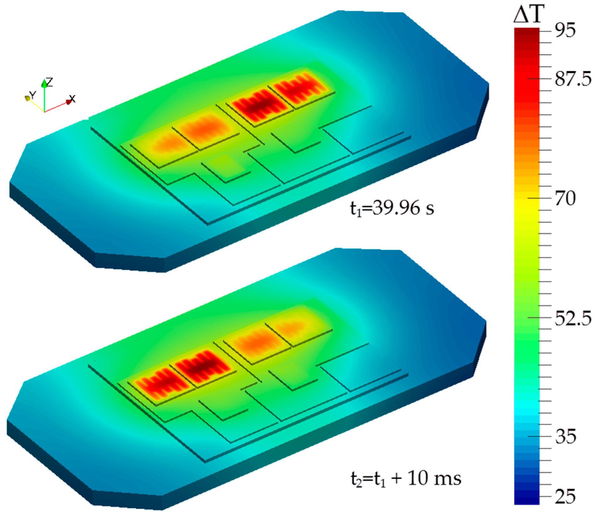
  • MPMM is extremely accurate since the model precision can be arbitrarily fixed a-priori, and it allows the determination of the temperature field over the whole power module.
  • Up to thousands of heat sources with linearly increasing complexity can be modeled [38,39].
  • DCTM equations are provided in a diagonal state-space representation, thus they can be suitably represented as IIR digital filters and implemented in a digital signal processor (DSP) architecture or through an FPGA, with the latter allowing for a shorter computation time. Decoupled state-space equations allow parallel computation of each state variable on FPGA.
In this work, the DCTM is obtained with the following MOR procedure [21,22]. The material properties and the boundary conditions are to be provided as input data, while the mesh can be obtained from commercial (e.g., Comsol Multiphysics [40] ) or open-source tools. The active devices inside the power module correspond to the n power dissipating regions and are identified as heat sources (HSs) for the model, thus defining the junction temperatures. With these hypotheses, the following equation can be written for the 2nd order FEM discretization:
M d x d t ( t ) + K x ( t ) = g ( t )
where M is the mass matrix, K is the stiffness matrix, and x(t) describes the temperature rise on each point of the mesh and is a row vector of N degrees of freedoms (DoFs). The local sources vector g(t) is given by:
g ( t ) = G P ( t )
where P(t) is the n DCTM input powers and G is a N × n matrix in which the elements of the n columns, gin, describe the power density distributions (uniform or with an assigned space-dependent profile). The column vector with n rows T(t) of the DCTM temperature rises due to the powers P(t) is given by:
T ( t ) = T 0 + G T x ( t )
where T0 is the ambient temperature. Equations (1)–(3) are to be coupled with suitable boundary conditions (thermal equilibrium with ambient is assumed at t = 0).
The adopted MOR procedure is fully automatic and relies on MPMM [35,36], which involves the solution of the thermal problem in a frequency domain, i.e., of linear algebraic systems instead of ordinary differential equations. In particular, the problem is evaluated by fixing the frequency at specific values automatically evaluated according to a single user-defined error parameter [21]. The frequency-domain heat conduction problem solutions at the aforementioned frequencies, each involving a simple system of linear equation, are denoted as moments. By resorting to suitable projection matrices, Equations (1)–(3) can be rewritten by exploiting a small number of DoFs n ^ << N as follows:
d ξ ^ d t + Λ ^ ξ ^ ( t ) = Γ ^ P ( t )
T ( t ) = Γ ^ T ξ ^ ( t )
x ( t ) = V ξ ^ ( t )
where Λ ^ is a diagonal matrix and ξ ^ 1 ,..., ξ ^ n ^ are the new state variables. These variables have no explicit physical meaning, but they allow the reconstruction of the temperature field in all the FEM mesh points using Equation (6) at any time instant in a post-processing step. Equations (4) and (5) are synthesized in the discrete domain in terms of an IIR filter, adopting Tustin’s approximation. All the equations of the system in Equation (4) can be solved simultaneously in a FPGA implementation because the matrix is diagonal. It is worth noting that the adopted MOR technique implies a fixed choice of the geometry, the material parameters, and the boundary conditions; any change in one of the above implies the need of a re-extraction ex novo of the thermal model. Nevertheless, the proposed model is adequately accurate for a first proof-of-concept study illustrating the general procedure. This model can be extended in more complex formulations, which can be boundary condition independent (BCI) and parametric [41,42,43].
Assuming normal operating conditions, i.e., constant stress in [10], in the simplest case, the module reliability distribution is evaluated as the product of the reliability distributions of the elements comprising the module (active devices, passives, …), assuming statistical independence of the failure events.

3. Experimental Results: Power Model Equipped with a Poorly Performing Heatsink

A power module rated at 114 A and 600 V, manufactured by Vishay [44] and comprising two IGBTs and two diodes is considered for the case-studies. Uniform power dissipation is assumed to be occurring at the top of the active devices. The module is equipped with a 2.5 K/W aluminum heatsink, as depicted in Figure 1. The upper portion of the module has been disregarded because it is immersed in a silicone gel, which inhibits the upward heat flow. Material parameters are assumed to be standard literature bulk values and the following boundary conditions have been chosen: (i) the heat transfer coefficient (HTC) is h = 11 W/m2K for the heatsink and the module baseplate free surface; (ii) the upper portion of the whole structure is assumed adiabatic. Figure 2 shows a detail of the mesh comprised of 1.8 M DoFs.
The thermal behavior is commonly described by a n × n thermal impedance matrix ZTH(t) [K/W], wherein each element ZTHij is defined as the average temperature rise over ambient of the i-th HS due to the application of a power step to the j-th HS, normalized to its amplitude:
Z T H i j ( t ) = Δ T i ( t ) P D j
Elements with i = j are denoted as self-heating thermal impedances, while off-diagonal terms represent the mutual thermal impedances, i.e., the thermal coupling occurring between HSs. The thermal resistance RTH represents the steady state value of the thermal impedance. ZTH can be computed by extracting a DCTM, which is then simulated [21], or with standard transient FEM simulations by activating one HS at a time, e.g., [32,33,34].
In this work, two validations of the model and its IIR implementation have been proposed; (a) standard FEM simulations are compared to the ones performed with the IIR filter; and (b) an experimental setup was built to compare the baseplate temperature estimation with the measurement of a thermocouple (Fluke 179) mounted on its surface. The transient FEM simulations performed with Comsol Multiphysics require approximately 8 h of processing for each curve of Figure 3 on a desktop PC equipped with an octa-core Intel i7-5960X and 64 GB RAM, leading to a total of 5 × 8 = 40 h for computing the whole ZTH(t) as required by fitting-based DCTMs, e.g., [18,20]. The proposed MOR procedure implemented in MATLAB lasts, instead, only 1.5 h for extracting Equations (4)–(6) with subsequent negligible time (1 s) for performing the ZTH(t) simulations, thus providing a fast model extraction.
Figure 3 reports the results for the validation step (a); in this case a unit power step on IGBT #1 has been applied, and the impedances computed by FEM and by the IIR filter are in good agreement. It is worth noting that the total thermal resistance obtained from the simulation is congruent to the one surmised from the datasheet of the heatsink and the power module [44]. Figure 3 shows that both the dynamic response and the steady-state are dominated by the added heatsink (the curve relative to the mutual impedance is very close to the curve of the heatsink), which is characterized by a greater Rth with respect to the maximum thermal resistance of the IGBT (equal to 0.38 K/W). Finally, Figure 3 reveals that the steady state is reached after more than 16 minutes.
In step (b) of the validation procedure, the thermal response of the IGBT module is experimentally analyzed by exploiting the setup depicted in Figure 4.
The circuit topology is a single-phase bidirectional half-bridge DC-AC converter, widely adopted in many power converter topologies [45,46,47,48]. In this experiment, the converter operates as an inverter connected to a 3 Ω resistive load, with a DC link voltage equal to 100 V.
The circuit is forced to operate with only a feed-forward control and the pulse-width modulation (PWM) gate signals are generated by a real-time hardware platform (dSpace ds1006) equipped with a FPGA Xilinx Virtex-5. The control algorithm is designed so as to provide a 50 Hz pure sine current over the load, emulating a grid-tied connection. The same FPGA hosts the measurement and the equivalent IIR filter of the thermal model.
Measurements were performed on the closed power module depicted in Figure 4. Short cables connect the power module to the measurement setup; no busbar is present. Differential voltage probes are directly on top of the terminals 3 and 5 for the high side, and on terminals 5 and 7 for low side, while open-loop Hall effect current probes are on the connection cables. The power dissipated by each device is measured by means of the two pairs of aforementioned sensors that allow the monitoring the voltage drop and the current flowing across both sides of the half bridge; the power dissipated by the IGBT is distinguished by that of the diode looking at the direction of the current.
In particular, the voltage probe is differential, with 50× attenuation, 1000 V full scale, and 50 MHz bandwidth. The current measurement is performed with a Hall-effect current clamp 5A full scale, resolution less than 1 mA with 120 MHz bandwidth, and typical accuracy less than 1% DC gain error. The dSpace ds1006 features an acquisition board DS5203 equipped with 6 14-bit ADCs (up to 10 Msps). The probe bandwidths are much higher than the switching frequency, thus allowing a correct input sampling. The current probe is the limiting factor in determining the overall precision. While the adopted setup is useful for a first proof-of-concept study, the full application potential can be achieved only by adopting an integrated setup on a PCB, which is currently under development, featuring integrated Hall-effect sensors as well as differential instrumentation amplifiers.
Figure 5 depicts the measured powers dissipated by the two pairs of devices that operate in the same semi-period of the output current, with IGBT #2 and Diode #1 conducting in the positive half-cycle and IGBT #1 and Diode #2 in the negative one. These powers are given as input to the IIR filter, the outputs of which are the junction temperature rises over ambient DT = TjT0 (T0 equal to 23 °C in the experiment), as shown in Figure 6.
The temperature measured by the thermocouple mounted on the baseplate at the end of thermal transient is lower with respect to the estimated value with a relative error of about 20%. However, it must be noted that the power data waveforms are obtained with high accuracy, while the error is most likely due to the uncertainty of the HTC.
A detailed measurement setup would involve either the use of optical fiber sensors [49], or the use of an infrared camera setup [12] that can be also used in a lock-in setup for improved accuracy [50]. While the two aforementioned measurement systems can, in principle, provide the best validation of the simulation data, we are nevertheless confident of the obtained results since the 3-D model used to extract the compact model is detailed in (i) describing the geometry with care and (ii) considering reference literature values for the material parameters. The only fitting parameter is given by the HTC, which can be improved, e.g., by computation starting from thermal resistance data [51] or with additional measurements [52].
The converter operates with an output current of only 7 Amps. Figure 6 shows that the temperature rises over ambient, reaching a steady state value of about 45 °C at 1200 s in the case of a 2.5 K/W heatsink. The inset of Figure 6 shows the behavior in steady state. In particular, the pure sine current at line frequency leads to thermal cycling at the same frequency. As a consequence, the thermal cycle of the four devices presents a period of 20 ms, with a sequence of heating and cooling half-cycles of 10 ms. The underperforming heatsink does not allow for wide temperature variations, which are in this case about 1 °C, which could be measured only by means of an IR camera.
Figure 7 illustrates an off-line post processing of the real-time data in Figure 6. The estimated temperature in each point of the structure can be reconstructed by the system, starting from the temperature of the active devices by resorting to Equation (6). The presence of the poorly performing heatsink causes a quite flat temperature distribution in the whole structure, confirming the results of Figure 3.

4. Power Model Equipped with an Effective Cooling System

In this second case, a forced convection cooling system with a thermal resistance of 0.2 K/W is considered. The power delivered to the load is considerably increased, forcing the current of the IGBTs and Diodes to come very close to the maximum rating. These operating conditions ensure wider temperature excursion and show how the proposed model captures the temperatures’ temporal and spatial variations, which cannot be easily measured in other ways.
Figure 8 compares the result obtained from the IIR filter with that of the standard FEM simulations; as in the previous section, the comparison reveals a good agreement. Moreover it is possible to observe a significant difference for transient response and steady state of the self-heating thermal impedance with respect to the mutual ones (rising at around 1 s). This result can be ascribed to the lower thermal resistance of the more effective cooling system. In this case, the mutual impedances differ from the baseplate response because the heat flux is mainly in the vertical direction with much lower lateral spreading.
Figure 9 depicts the temperature increment estimation of the baseplate, IGBTs, and diodes. Even if the module dissipates more power, the more effective cooling system assures that Tj is lower than 150 °C (T0 is 23 °C). The thermal steady-state is reached quicker in comparison to Figure 6, as also shown in Figure 8.
The post processing process performed through Equation (6) has been performed on the results of Figure 9 in order to obtain thermal maps of the power module in Figure 10. These two off-line thermal maps show clearly the 20 ms cycles of Tj. In this operating condition, it can be inferred that the module robustness is heavily affected due to temperature variations of a magnitude higher than 10 °C. Such a wide swing causes thermo-mechanical stresses such as die-attach and die-solder fatigue [9]. Models such as Miner’s [53] take into account the thermal cycles to perform an accurate prediction of the module lifetime. However, no effective solutions have been available so far to provide an on-line thermal monitoring, which properly tracks these temperature variations.

5. Conclusions

This work has presented an innovative strategy to perform real-time on-line estimation of the junction temperature of switching devices embedded in a power module. This procedure is based on an accurate DCTM, which can be efficiently implemented on a FPGA platform by means of parallel IIR filters. The fast thermal response occurring in a power model equipped with a low RTH cooling system is effectively tracked, as confirmed by simulations and experimental results. In this operating condition, the large temperature variations at the grid frequency severely affect the robustness of the module to resist to both solder fatigue and bond wire lift-off degradation.
The variation in the mean output power supplied by the converter produces low frequency oscillations superposed to the previous ones, thus complicating the lifetime estimation of the devices.
Therefore, the proposed model represents an interesting option to increase the accuracy of on-line appliance health monitoring systems.

Author Contributions

Vincenzo D’Alessandro, Lorenzo Codecasa, and Alessandro Magnani were involved in the calibration of the thermal model. Fabio Di Napoli, Marino Coppola, Pierluigi Guerriero, Santolo Daliento, and Pietro Tricoli were involved in its hardware implementation. Vincenzo D’Alessandro, Lorenzo Codecasa, Pietro Tricoli, and Santolo Daliento conceived and designed the experiments. Fabio Di Napoli, Marino Coppola, and Pierluigi Guerriero performed the experiments, while Vincenzo D’Alessandro and Alessandro Magnani analyzed the data. Vincenzo D’Alessandro, Lorenzo Codecasa, Pietro Tricoli, Fabio Di Napoli, and Santolo Daliento wrote the paper.

Conflicts of Interest

The authors declare no conflict of interest.

References

  1. Di Napoli, F.; Guerriero, P.; D’Alessandro, V.; Daliento, S. A Power Line Communication on DC bus with photovoltaic strings. In Proceedings of the 3rd Renewable Power Generation Conference (RPG), Naples, Italy, 24–25 September 2014.
  2. Guerriero, P.; Vallone, G.; Primato, M.; Di Napoli, F.; Di Nardo, L.; D’Alessandro, V.; Daliento, S. A wireless sensor network for the monitoring of large PV plants. In Proceedings of the 2014 International Symposium on Power Electronics, Electrical Drives, Automation and Motion (SPEEDAM), Ischia, Italy, 18–20 June 2014; pp. 960–965.
  3. Di Napoli, F.; Guerriero, P.; D’Alessandro, V.; Daliento, S. Single panel voltage zeroing system for safe access on PV plants. IEEE J. Photovolt. 2015, 5, 1428–1434. [Google Scholar] [CrossRef]
  4. Guerriero, P.; Di Napoli, F.; Vallone, G.; D’Alessandro, V.; Daliento, S. Monitoring and Diagnostics of PV Plants by a wireless self-powered sensor for individual panel. IEEE J. Photovolt. 2016, 6, 286–294. [Google Scholar] [CrossRef]
  5. D’Alessandro, V.; Di Napoli, F.; Guerriero, P.; Daliento, S. An automated high-granularity tool for a fast evaluation of the yield of PV plants accounting for shading effects. Renew. Energy 2015, 83, 294–304. [Google Scholar] [CrossRef]
  6. Yang, S.; Bryant, A.; Mawby, P.; Xiang, D.; Li, R.; Tavner, P. An industry-based survey of reliability in power electronic converters. In Proceedings of the Energy Conversion Congress and Exposition (ECCE), San Jose, CA, USA, 20–24 September 2009; pp. 3151–3157.
  7. Yang, S.; Bryant, A.; Mawby, P.; Xiang, D.; Li, R.; Tavner, P. An industry-based survey of reliability in power electronic converters. IEEE Trans. Ind. Appl. 2011, 47, 1441–1451. [Google Scholar] [CrossRef]
  8. Daliento, S.; Mele, L. Approximate closed-form analytical solution for minority carrier transport in opaque heavily doped regions under illuminated conditions. IEEE Trans. Electron Devices 2006, 53, 2837–2838. [Google Scholar] [CrossRef]
  9. Ciappa, M. Selected failure mechanisms of modern power modules. Microelectron. Reliab. 2002, 42, 653–667. [Google Scholar] [CrossRef]
  10. Nelson, W.B. Accelerated Testing: Statistical Models, Test Plans, and Data Analysis; John Wiley & Sons: Hoboken, NJ, USA, 2009. [Google Scholar]
  11. Herr, E.; Poe, A.; Fox, A. Reliability evaluation and prediction for discrete semiconductors. IEEE Trans. Reliab. 1980, 29, 208–216. [Google Scholar] [CrossRef]
  12. Choi, U.M.; Jørgensen, S.; Blaabjerg, F. Advanced accelerated power cycling test for reliability investigation of power device modules. IEEE Trans. Power Electron. 2016, 31, 8371–8386. [Google Scholar] [CrossRef]
  13. Romano, G.; Riccio, M.; De Falco, G.; Maresca, L.; Irace, A.; Breglio, G. An ultrafast IR thermography system for transient temperature detection on electronic devices. In Proceedings of the 30th Annual Semiconductor Thermal Measurement and Management Symposium (SEMI-THERM), San Jose, CA, USA, 9–13 March 2014; pp. 80–84.
  14. Ghimire, P.; de Vega, A.R.; Beczkowski, S.; Rannestad, B.; Munk-Nielsen, S.; Thogersen, P. Improving Power Converter Reliability: Online Monitoring of High-Power IGBT Modules. IEEE Ind. Electron. Mag. 2014, 8, 40–50. [Google Scholar] [CrossRef]
  15. Ghimire, P.; Pedersen, K.B.; Vega, A.R.; Rannestad, B.; Munk-Nielsen, S.; Thogersen, P.B. A real time measurement of junction temperature variation in high power IGBT modules for wind power converter application. In Proceedings of the 30th Annual Semiconductor Thermal Measurement and Management Symposium (SEMI-THERM), San Jose, CA, USA, 9–13 March 2014; pp. 1–6.
  16. Yang, S.; Xiang, D.; Bryant, A.; Mawby, P.; Ran, L.; Tavner, P. Condition Monitoring for Device Reliability in Power Electronic Converters: A Review. IEEE Trans. Power Electron. 2010, 25, 2734–2752. [Google Scholar] [CrossRef]
  17. Musallam, M.; Johnson, C.M. Real-time compact thermal models for health management of power electronics. IEEE Trans. Power Electron. 2010, 25, 1416–1425. [Google Scholar] [CrossRef]
  18. Huang, H.; Mawby, P.A. A lifetime estimation technique for voltage source inverters. IEEE Trans. Power Electron. 2013, 28, 4113–4119. [Google Scholar] [CrossRef]
  19. Musallam, M.; Yin, C.; Bailey, C.; Johnson, C.M. Mission profile-based reliability design and real-time life consumption estimation in power electronics. IEEE Trans. Power Electron. 2015, 30, 2601–2613. [Google Scholar] [CrossRef]
  20. Ye, J.; Yang, K.; Ye, H.; Emadi, A. A fast electro-thermal model of traction inverters for electrified vehicles. IEEE Trans. Power Electron. 2017, 32, 3920–3934. [Google Scholar] [CrossRef]
  21. Codecasa, L.; D’Alessandro, V.; Magnani, A.; Rinaldi, N.; Zampardi, P.J. Fast novel thermal analysis simulation tool for integrated circuits (FANTASTIC). In Proceedings of the 20th International Workshop on Thermal Investigations of ICs and Systems (THERMINIC), London, UK, 24–26 September 2014.
  22. Magnani, A.; Di Napoli, F.; Riccio, M.; Guerriero, P.; D’Alessandro, V.; Breglio, G.; Daliento, S.; Irace, A.; Rinaldi, N.; Codecasa, L. Thermal feedback blocks for fast and reliable electrothermal circuit simulation of power circuits at module level. In Proceedings of the 28th International Symposium on Power Semiconductor Devices and ICs (ISPSD), Prague, Czech Republic, 12–16 July 2016; pp. 187–190.
  23. Fukahori, K.; Gray, P.R. Computer simulation of integrated circuits in the presence of electrothermal interaction. IEEE J. Solid-State Circuits 1976, 11, 834–846. [Google Scholar] [CrossRef]
  24. Hefner, A.R.; Blackburn, D.L. Simulating the dynamic electrothermal behavior of power electronic circuits and systems. IEEE Trans. Power Electron. 1993, 8, 376–385. [Google Scholar] [CrossRef]
  25. Rinaldi, N. On the modeling of the transient thermal behavior of semiconductor devices. IEEE Trans. Electron Devices 2001, 48, 2796–2802. [Google Scholar] [CrossRef]
  26. Kwok, K.H.; D’Alessandro, V. Fast analytical modeling of dynamic thermal behavior of semiconductor devices and circuits. IEEE Trans. Electron Devices 2014, 61, 1031–1038. [Google Scholar] [CrossRef]
  27. Székely, V. On the representation of infinite-length distributed RC one-ports. IEEE Trans. Circuits Syst. 1991, 38, 711–719. [Google Scholar] [CrossRef]
  28. Székely, V. Identification of RC networks by deconvolution: Chances and limits. IEEE Trans. Circuits Syst. I 1998, 45, 244–258. [Google Scholar] [CrossRef]
  29. Jakopović, Z.; Benĉić, Z.; Konćar, R. Identification of thermal equivalent-circuit parameters for semiconductors. In Proceedings of the Workshop on Computers in Power Electronics, Lewisburg, PA, USA, 5–7 August 1990; pp. 251–260.
  30. D’Alessandro, V.; Magnani, A.; Riccio, M.; Iwahashi, Y.; Breglio, G.; Rinaldi, N.; Irace, A. Analysis of the UIS behavior of power devices by means of SPICE-based electrothermal simulations. Microelectron. Reliab. 2013, 53, 1713–1718. [Google Scholar] [CrossRef]
  31. D’Alessandro, V.; de Magistris, M.; Magnani, A.; Rinaldi, N.; Grivet-Talocia, S.; Russo, S. Time domain dynamic electrothermal macromodeling for thermally aware integrated system design. In Proceedings of the 17th IEEE Workshop on Signal and Power Integrity (SPI), Paris, France, 12–15 May 2013.
  32. D’Alessandro, V.; Magnani, A.; Riccio, M.; Breglio, G.; Irace, A.; Rinaldi, N.; Castellazzi, A. SPICE modeling and dynamic electrothermal simulation of SiC power MOSFETs. In Proceedings of the IEEE 26th International Symposium on Power Semiconductor Devices & IC’s (ISPSD), Waikoloa, HI, USA, 15–19 June 2014; pp. 285–288.
  33. De Tommasi, L.; Magnani, A.; D’Alessandro, V.; de Magistris, M. Time domain identification of passive multiport RC networks with convex optimization: An application to thermal impedance macromodeling. In Proceedings of the 18th IEEE Workshop on Signal and Power Integrity (SPI), Ghent, Belgium, 11–14 May 2014.
  34. D’Alessandro, V.; De Magistris, M.; Magnani, A.; Rinaldi, N.; Russo, S. Dynamic electrothermal macromodeling: An application to signal integrity analysis in highly integrated electronic systems. IEEE Trans. Compon. Packag. Manuf. Technol. 2013, 3, 1237–1243. [Google Scholar] [CrossRef]
  35. Codecasa, L.; D’Amore, D.; Maffezzoni, P. Parameters for Multi-Point Moment Matching reduction of discretized thermal networks. In Proceedings of the IEEE Therminic, Madrid, Spain, 1–4 October 2002; pp. 151–154.
  36. Codecasa, L.; D’Amore, D.; Maffezzoni, P. An Arnoldi based thermal network reduction method for electro-thermal analysis. IEEE Trans. Compon. Packag. Technol. 2003, 26, 186–192. [Google Scholar] [CrossRef]
  37. D’Alessandro, V.; Magnani, A.; Codecasa, L.; Di Napoli, F.; Guerriero, P.; Daliento, S. Dynamic electrothermal simulation of photovoltaic plants. In Proceedings of the International Conference on Clean Electrical Power (ICCEP), Taormina, Italy, 16–18 June 2015; pp. 682–688.
  38. Codecasa, L.; Magnani, A.; D’Alessandro, V.; Rinaldi, N.; Metzger, A.G.; Bornoff, R.; Parry, J. Novel MOR approach for extracting dynamic compact thermal models with massive numbers of heat sources. In Proceedings of the 32nd Annual Semiconductor Thermal Measurement and Management Symposium (SEMI-THERM), San Jose, CA, USA, 14–17 March 2016.
  39. Codecasa, L.; D’Alessandro, V.; Magnani, A.; Rinaldi, N. Novel partition-based approach to dynamic compact thermal modeling. In Proceedings of the 22nd International Workshop on Thermal Investigations of ICs and Systems (THERMINIC), Budapest, Hungary, 21–23 September 2016.
  40. Comsol Multiphysics, User’s Guide; release 5.2A; COMSOL Inc.: Burlington, MA, USA, 2016.
  41. Sabry, M.-N. Dynamic compact thermal models used for electronic design: A review of recent progress. In Proceedings of the International Electronic Packaging Technical Conference and Exhibition, Maui, HI, USA, 6–11 June 2003; 2003; pp. 399–415. [Google Scholar]
  42. Lasance, C.J.M. Ten years of boundary-condition-independent compact thermal modeling of electronic parts: A review. Heat Transf. Eng. 2008, 29, 149–168. [Google Scholar] [CrossRef]
  43. Sabry, M.-N.; Dessouky, M. A framework theory for dynamic compact thermal models. In Proceedings of the 28th Annual IEEE Semiconductor Thermal Measurement and Management Symposium (SEMI-THERM), San Jose, CA, USA, 18–22 March 2012; pp. 189–194.
  44. VS-50MT060WHTAPbF Half Bridge IGBT MTP (Warp Speed IGBT), 114 A, Vishay, 2015. Available online: http://www.vishay.com/docs/94468/vs-50mt060whtapbf.pdf (accessed on 5 November 2015).
  45. Coppola, M.; Daliento, S.; Guerriero, P.; Lauria, D.; Napoli, E. On the design and the control of a coupled-inductors boost dc-ac converter for an individual PV panel. In Proceedings of the IEEE 21st International Symposium on Power Electronics, Electrical Drives, Automation and Motion (SPEEDAM), Sorrento, Italy, 20–22 June 2012; pp. 1154–1159.
  46. Guerriero, P.; Di Napoli, F.; D’Alessandro, V.; Daliento, S. Accurate maximum power tracking in photovoltaic systems affected by partial shading. Int. J. Photoenergy 2015, 2015, 824832. [Google Scholar] [CrossRef]
  47. Coppola, M.; Guerriero, P.; Di Napoli, F.; Daliento, S.; Lauria, D. A PV AC-module on coupled-inductors boost DC/AC converter. In Proceedings of the IEEE International Symposium on Power Electronics, Electrical Drives, Automation and Motion (SPEEDAM), Taormina, Italy, 18–20 June 2014; pp. 1015–1020.
  48. Coppola, M.; Di Napoli, F.; Guerriero, P.; Iannuzzi, D.; Daliento, S.; Del Pizzo, A. An FPGA-based advanced control strategy of a grid tied PV CHB inverter. IEEE Trans. Power Electron. 2016, 31, 806–816. [Google Scholar] [CrossRef]
  49. Carubelli, S.; Khatir, Z. Experimental validation of a thermal modelling method dedicated to multichip power modules in operating conditions. Microelectron. J. 2003, 34, 1143–1151. [Google Scholar] [CrossRef]
  50. Riccio, M.; Breglio, G.; Irace, A.; Spirito, P. An equivalent time temperature mapping system with a 320 × 256 pixels full-frame 100 kHz sampling rate. Rev. Sci. Instrum. 2007, 78, 106106. [Google Scholar] [CrossRef] [PubMed]
  51. Garegnani, G.; Fiori, V.; Gouget, G.; Monsieur, F.; Tavernier, C. Wafer level measurements and numerical analysis of self-heating phenomena in nano-scale SOI MOSFETs. Microelectron. Reliabil. 2016, 63, 90–96. [Google Scholar] [CrossRef]
  52. Samson, A.; Janicki, M.; Raszkowski, T.; Zubert, M. Determination of average heat transfer coefficient value in compact thermal models. In Proceedings of the 17th International Conference on Thermal, Mechanical and Multi-Physics Simulation and Experiments in Microelectronics and Microsystems (EuroSimE), Montpellier, France, 18–20 April 2016.
  53. Miner, M. Cumulative damage in fatigue. J. Appl. Mech. 1945, 12, 159–164. [Google Scholar]
Figure 1. Comsol Multiphysics 3-D structure of the IGBT power module under test, equipped with an aluminum heatsink in free convection.
Energies 10 00189 g001
Figure 2. (a) Full image; and (b) detail of the 3-D mesh of the module depicted in Figure 1.
Energies 10 00189 g002
Figure 3. Comparison between standard FEM and DCTM self and mutual thermal impedances, obtained by applying a unit power step on IGBT #1 with a 2.5 K/W heatsink.
Energies 10 00189 g003
Figure 4. Schematic of the circuit employed for the experimental test.
Energies 10 00189 g004
Figure 5. Measurements of the power dissipated by the active devices of the module under test; (a) shows the power dissipated by the pair composed by IGBT #1 and Diode #2, while (b) illustrates the other ones. A 1 ms window detail of (a) and (b) are reported in plots (c) and (d), respectively. In particular, (c) is a zoom of (a) starting from tp1 = 12 ms, while (d) is a zoom of (b) starting from tp2 = 3 ms.
Energies 10 00189 g005
Figure 6. Estimated variation of IGBTs, diodes, and baseplate temperature rises for the module under test mounted on a 2.5 K/W heatsink. Details about the steady state response highlighting the temperature cycles are depicted in the inset.
Energies 10 00189 g006
Figure 7. Two temperature maps at the time instants t1 = 299.845 s and t2 = 1199.395 s of the module under test equipped with a 2.5 K/W heatsink.
Energies 10 00189 g007
Figure 8. Self and mutual thermal impedances obtained by applying a unit power step on IGBT #1 to the module mounted on a 0.2 K/W heatsink; comparison between standard FEM and DCTM results.
Energies 10 00189 g008
Figure 9. Estimated variation of IGBTs, diodes, and baseplate temperature rises for the module mounted on a 0.2 K/W heatsink. The inset shows that swings are much wider than those reported for the previous case in Figure 6.
Energies 10 00189 g009
Figure 10. Two temperature maps at the time instants t1 = 39.96 s and t2 = t1 + 10 ms of the module mounted on a 0.2 K/W heatsink.
Energies 10 00189 g010

