Article

Integration of Electric Springs and Multi-Port Transformers—A New Solution for AC Microgrids with Renewable Energy Sources

1
School of Electrical Engineering, Southeast University, 2 SiPaiLou, Nanjing 210096, Jiangsu, China
2
Department of Industrial Engineering, University of Padova, 35131 Padova, Italy
*
Author to whom correspondence should be addressed.
Energies 2017, 10(2), 193; https://doi.org/10.3390/en10020193
Submission received: 1 January 2017 / Revised: 24 January 2017 / Accepted: 4 February 2017 / Published: 9 February 2017
(This article belongs to the Special Issue Advanced Operation and Control of Smart Microgrids)

Abstract

:
The new concept of integrating electric springs (ESs) and multi-port transformers (MTPs) as an active solution for energy management in alternating current (AC) microgrids is proposed. With an ES located at the port where storage devices previously were, the so-called critical flux is regulated to a constant value within the core of the transformer. The voltage on each winding is then clamped so that critical load (CL) voltage is regulated to a predefined value. The integration of ESs and MPTs can ensure a safer environment for ES utilization. Thus, the power generated by renewable energy sources can be safely used at residential locations with no need to worry about voltage fluctuations across CLs. Moreover, users can sell electricity to the power companies considered as CLs when the electricity generation of the AC microgrids or the home-installed renewable energy resources exceeds the personal consumption. In the paper, isolated topologies for ESs with three- and four-port transformers are examined, and a theoretical analysis of the ES operation is carried out. Then, equivalent circuits of the isolated ES topologies have been derived. Analysis of the ES operation and effectiveness of the isolated ES topologies are validated by both simulations and experiments.

1. Introduction

AC microgrids with renewable energy sources (RESs) are becoming more and more popular all over the world; they may contain various energy sources, such as wind and solar, and loads along with batteries for the energy storage [1]. The power systems in stand-alone self-sufficient residential buildings are typical applications. However, the random nature of RESs hinders the direct exploitation of their power generation capabilities [2]. The usage of storage devices is the traditional solution deployed to cope with the nature of RESs. Such a solution depends on the integrity of the storage devices and leads to cost increases [3]. Another solution consists in the direct load control or on-off control of smart loads (SLs) [4] as, for example, the water heaters used in Denmark. Although matching the power demand with the generation, this solution necessitates extra electrical devices and communication buses, which may lead to higher cost and lower system reliability. Another solution relies on the utilization of DC-DC multi-port converters (MPCs) but they need a large number of converters (as many as the ports) and an intricate control system [5]. In general, in MPCs the power sources are located at some ports, the loads at other ports and the batteries at another port [6,7]. Against this background, the availability of an AC solution that preserves the loads from the power source fluctuations while reducing the converter count and partially or fully dispensing of storage devices could promote a large utilization of AC microgrids with RESs. To this aim, resorting to electric springs (ESs) could provide an affordable solution.
ESs have been recently conceived as a technique able to balance power demand and generation automatically [8,9,10,11,12,13,14,15,16,17] and, indeed, they have been proven useful in stabilizing the magnitude of the AC voltage by which RESs supply the loads. The initial conception of ESs was intended to compensate for the reactive power only [8], whilst its extension to mixed active-reactive power compensation modes was presented in [9]. In these papers, the definition of smart load (SL) is given together with those of critical load (CL) and non-critical load (NCL). For the record, CL is a load with a restricted operating voltage range, NCL is a load with somewhat wider operating voltage range, and SL is the composite of ES and NCL. Setups in [8,9] can be considered as the first (ES-1) and second version (ES-2) of ESs, respectively. Successively, the concept of active suspension has been incorporated into ESs, with the purpose of stabilizing voltage magnitude and frequency of bidirectional grid-connected converters interfacing RESs with the grid [10]; the relevant setup can be considered as the third version (ES-3) of ESs, even if it does make provision for any NCL.
So far, non-isolated ES topologies have been extensively studied. Isolated ES topologies are mentioned in [11,12], most of which are intended for three-phase applications, but no paper has reported full isolation between SLs, CLs and input power sources.
In this paper, the concept of fully isolated ESs is proposed, where isolation is achieved by integrating ESs and multi-port transformers (MPTs). The proposed solution offers several advantages over the existing ESs as well as over MPCs. Compared to the existing ESs, it ensures a safer environment for the users because the network participants, namely power line, SLs and CLs, are isolated galvanically each other; the isolation—for instance—is mandatory when RES is a PV field with a rail connected to Earth, as per EN 50438 standards emanated by IEC. In addition, a fully isolated ES greatly extends the applications of the ES equipment because of its many features, documented later on, like the voltage magnitude stabilization of more CLs operating at different voltage levels and the opportunity for the users to sell high-quality electricity to the power companies when the electricity generation of the AC microgrids or the home-installed RESs exceed the personal consumption. For this reason, the concept of fully isolated ES can be regarded as the fourth version (ES-4) of ESs. Compared to MPCs, the fully isolated ESs enjoy the known ES merits, namely they need only one converter and eliminate any charging-discharging process of the DC source feeding ES when operated in reactive power compensation mode. Consequently, the integration of ESs and MPTs facilitates the deployment of ES equipment in distributed power systems and, more generally, opens the door to its extensive usage in a variety of applications [18,19] such as the power generation from solar panels on the roof or small wind turbines at domestic homes. Besides the technical benefits, the proposed solution will stimulate the application of power generation from RESs, especially in residential areas. Compared to traditional fossil energy, great economic benefits is achieved by using RESs [20,21,22] as it is evidenced by the fact that many countries have adopted policies to encourage the power generation from RESs [23,24,25].
In detail, the paper is organized as follows: Section 2 reviews the non-isolated ES topology and introduces the fully isolated ES topologies with three- (TPT) and four- (FPT) port transformer which are taken as study cases to illustrate the merits of the proposed solution. Section 3 provides a control-oriented analysis of the fully isolated ES topologies. Section 4 investigates the applicative potentials of the fully isolated ES topologies. Section 5 reports simulations on the investigated matter and discusses the results. Section 6 gives experimental results that validate the theoretical findings. Section 7 concludes the paper.
By convention, throughout the paper the time-variable quantities are denoted with lower case letters, the DC and rms quantities with upper case letters and the vector quantities with upper case letters topped by an arrow.

2. Fully Isolated vs. Non-Isolated ES Topology

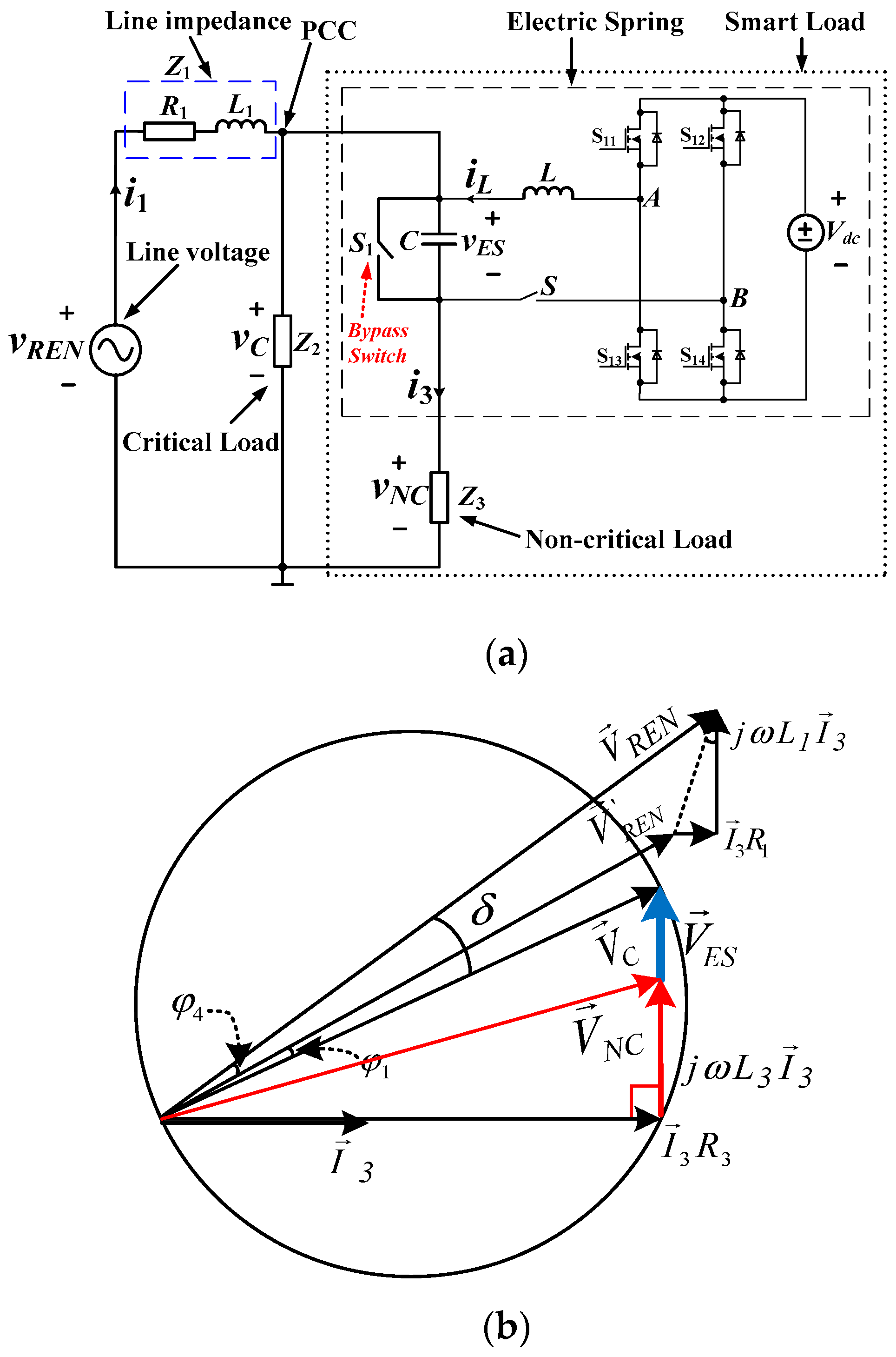
2.1. Non-Isolated ES Topology

Non-isolated ES topologies, when embedded in a power system, have the schematics illustrated in Figure 1a [13], where vREN is the line voltage, Z1 is the line impedance, Z2 is the CL impedance, Z3 is the NCL impedance, and vC and vNC are the voltages across CL and NCL. The magnitude of the line voltage is subjected to changes, especially if the line is fed by power sources like RESs that exhibit uncontrolled variations in their output voltage. Vector subtraction of the line voltage from the voltage drop across the line impedance gives the voltage at the point of common coupling (PCC).
ES has the circuitry enclosed by the dashed line in Figure 1a and includes a single-phase inverter and a low-pass filter. In turn, SL has the circuitry enclosed by the dotted line in the same figure and is connected in parallel to CL at PCC. Switch S1 is of bypass type: when open, SL is activated; when closed, SL is deactivated and capacitor C is shortened to prevent possible oscillating operation of the topology. Switch S cuts off the connection between SL and the inverter.

2.2. Non-Isolated ES Topology Operation

Figure 1b shows the vector diagram of the circuitry in Figure 1a when ES operates in the so-called inductive mode, which occurs when the rms value VREN of the line voltage is somewhat greater than its nominal value as drawn in the diagram of Figure 1b. The ES control is executed by imposing the nominal line voltage for V C and the angle δ by which V C lags V R E N . Details on the ES control system, including the calculation of angle δ, can be found in [13]; worth to note, this calculation relies on the knowledge of the impedance of transmission line.

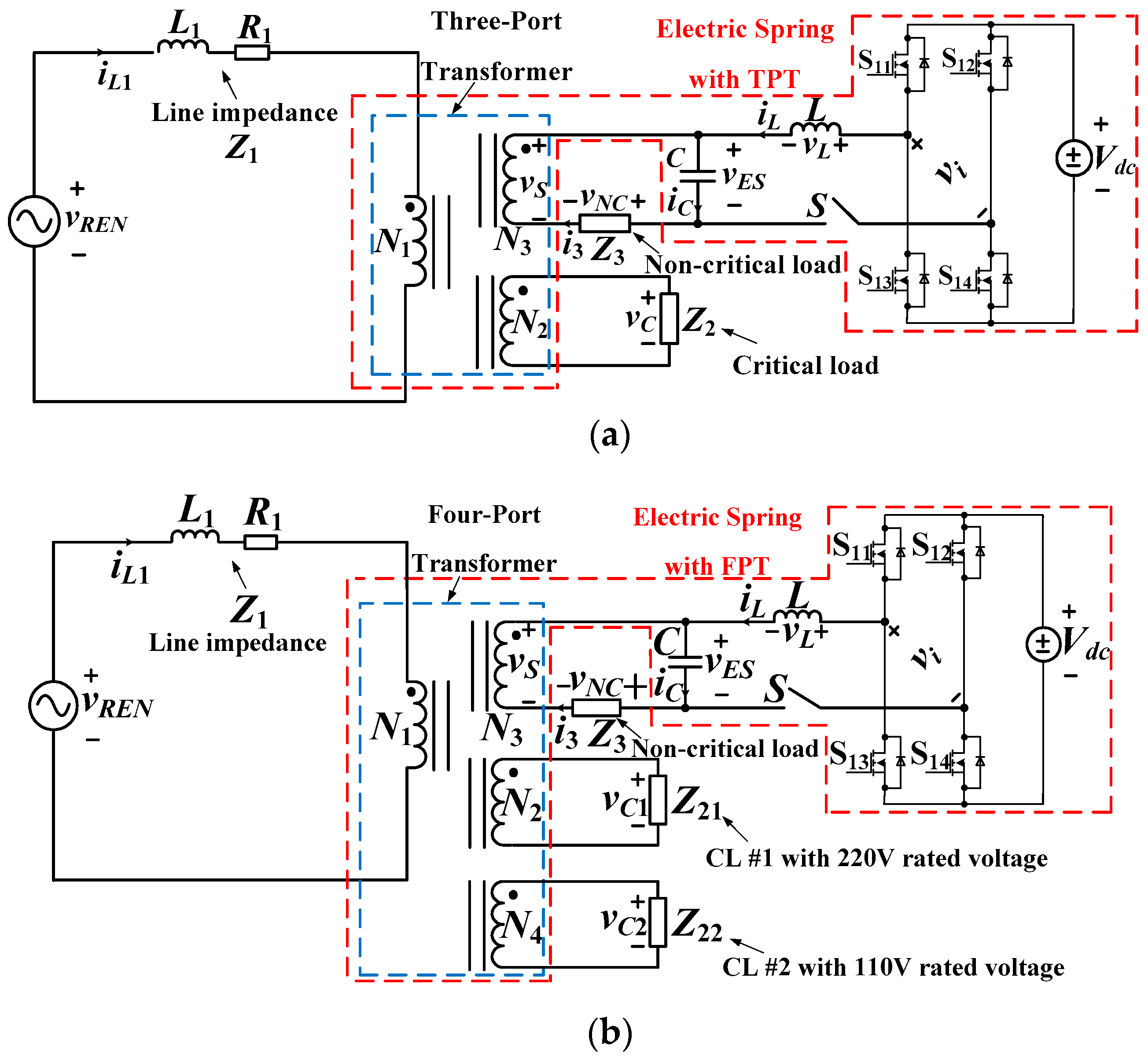
2.3. Fully Isolated ES Topology

Previous works have dealt with non-isolated ES topologies like that one of Figure 1a. They are liable to be unsafe since they do not provide any isolation between the network participants, in particular between the power line and the two types of load (SL and CL). To face this issue, fully isolated topologies obtained by integrating ESs and MPTs are proposed and investigated in this paper.
The schematics of the fully isolated ES topologies with TPT and FTP are shown in Figure 2a,b, respectively. In these topologies, the network participants are connected to the ports of the transformer, where the ports can be identified by the turn number of the relevant windings. For example, for the fully isolated TPT-based ES topology in Figure 2a, the power line is connected to port N1, CL to port N2 and SL to port N3. It is evident that here the power line, SL and CL do not have any galvanic contact each other.
The windings of the transformer in Figure 2a are crossed by an equal flux per turn. If this flux is regulated at a constant level of proper value, hereafter termed as critical flux level, the voltages of all the ports are kept constant. Specifically, the voltage of port N2 connected to CL is kept at the desired value regardless of line voltage variations. Regulation of the transformer flux at the critical flux level is exerted by SL at port N3.

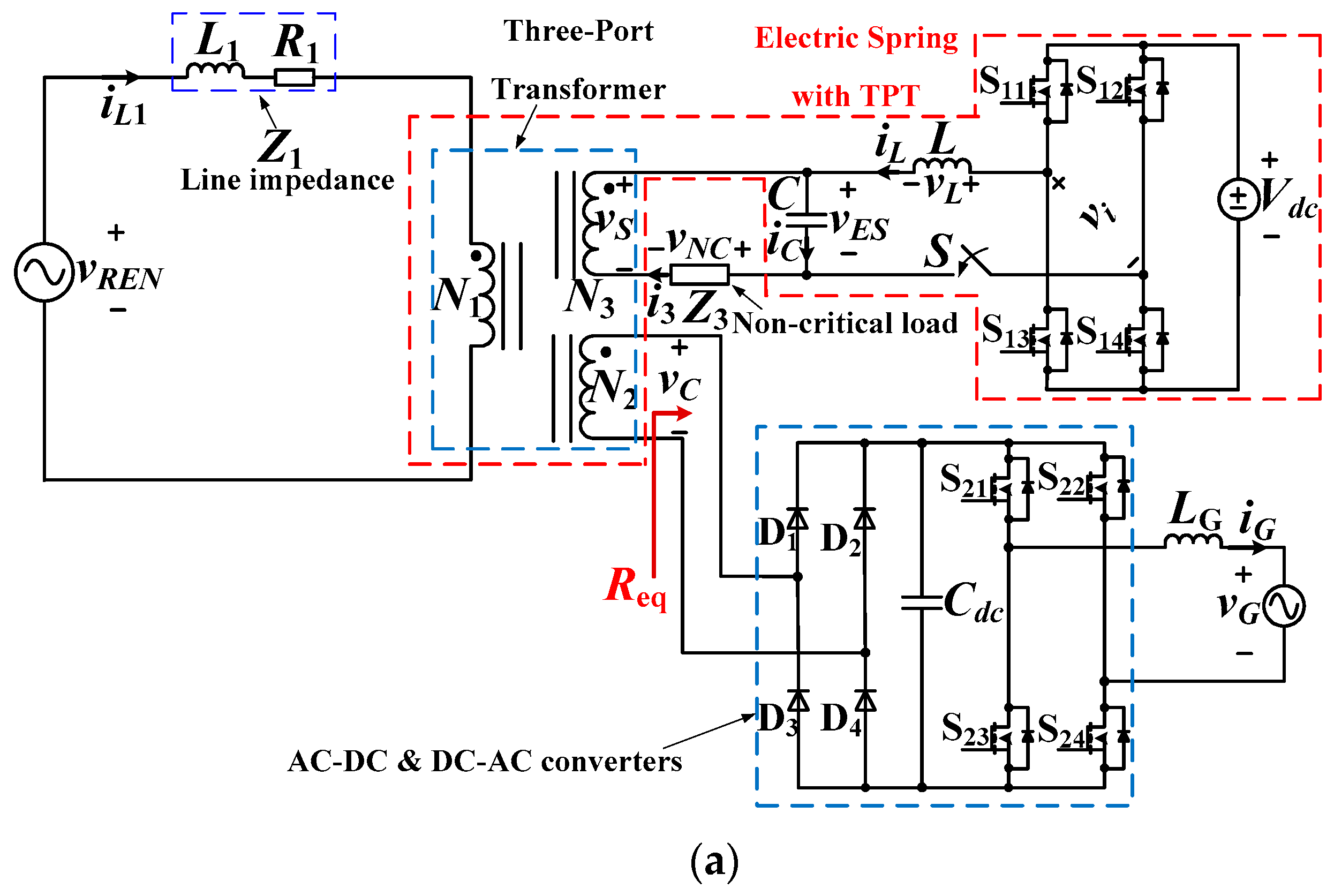
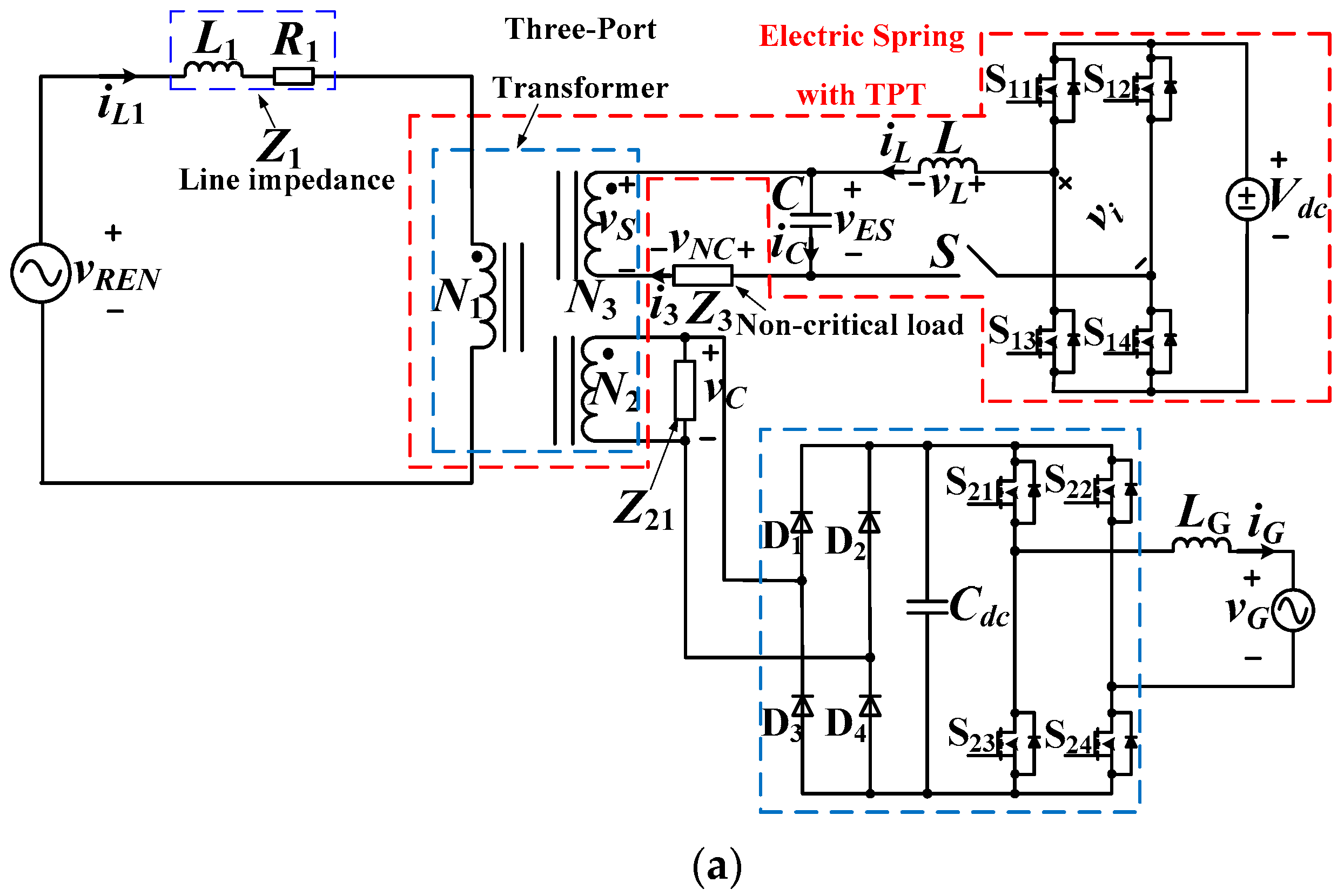
2.4. Fully Isolated FPT-Based ES Topology

Normally, CLs are rated for an equal voltage (e.g., 220 V). However, neither a non-isolated ES topology nor the fully isolated TPT-based topology is capable of handling more CLs with different DC voltages. In the future, some critical, residential equipment could be supplied by stabilized low DC voltage, obtained by rectification of low AC voltage. To meet the demand of having different rated voltages, it comes in handy the fully isolated FPT-based ES topology, arranged by adding another port, designated with N4 in Figure 2b, to the TPT in Figure 2a. By setting the turn ratio N3:N4 at 2:1, CL #1 (Z21) can be supplied at 220 V and CL #2 (Z22) at 110 V, respectively. Once the transformer flux is regulated by SL, the voltages of both CLs are kept constant at the respective level. More in general, fully isolated topologies with MPT do not need an ES for each CL with specific rated voltage, but only one ES is enough to regulate the voltage of all the ports. It can be easily figured out how this feature may lead to great opportunities in distributed power generation systems.

3. Control-Oriented Analysis of Fully Isolated ES Topology

In this Section, the operation of the fully isolated ES topologies in Figure 2a,b are analyzed to finalize their control. For this purpose, the derivation of an equivalent circuit for the fully isolated topologies comes useful. To simplify the derivation, the transformers are assumed ideal, i.e., with no leakage inductance and zero magnetizing current.

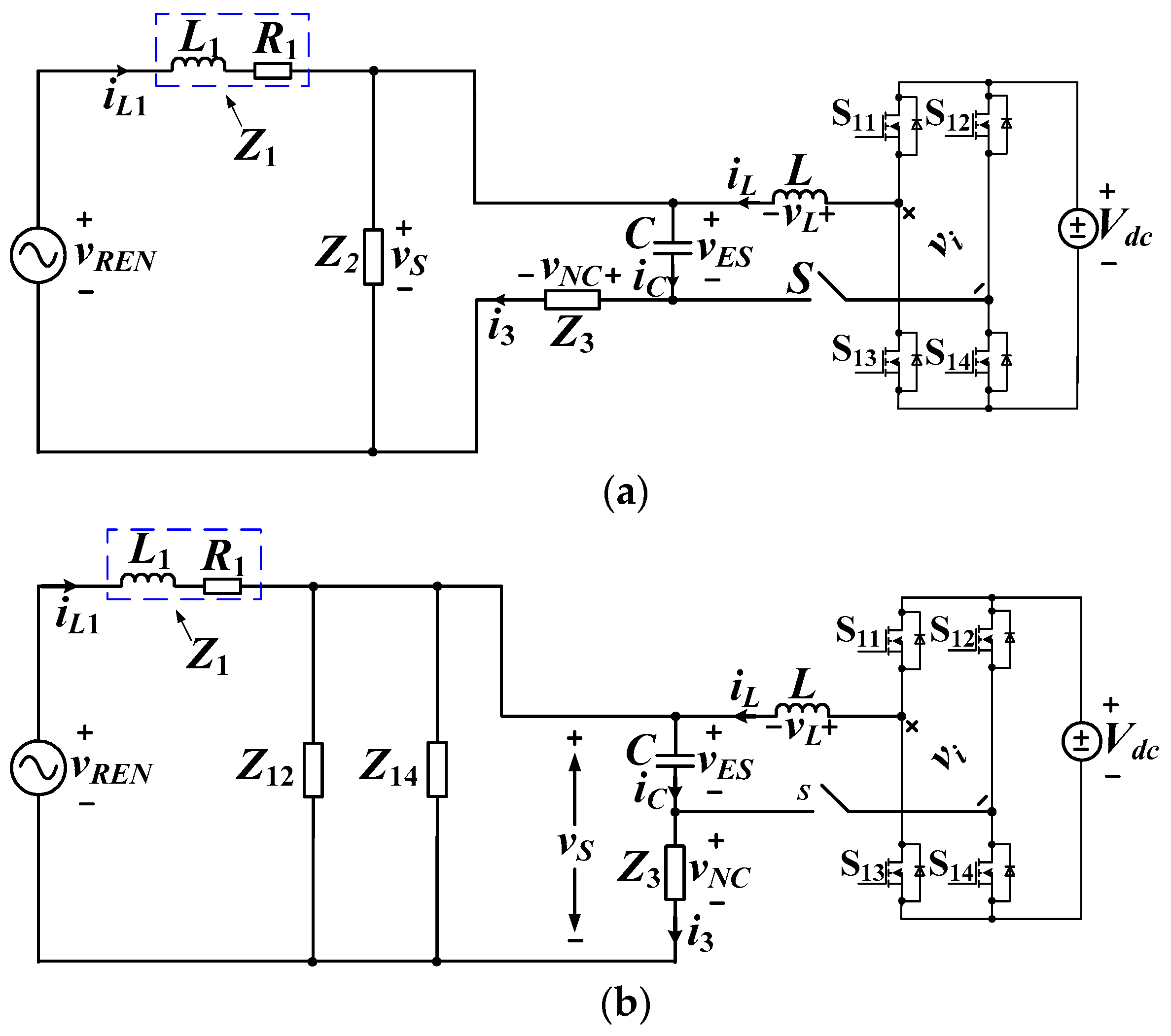
3.1. Fully Isolated TPT-Based ES Topology

Without loss of generality, turn ratio N1:N2:N3 of TPT is set at 1:1:1. Then, for an ideal TPT, the equivalent circuit of Figure 2a becomes as in Figure 3a.
Comparison of Figure 3a with Figure 1a shows that the equivalent circuit is the same as that of the non-isolated ES topology and, therefore, the control of a fully isolated ES can be executed by means of the existing techniques, such as the δ technique.

3.2. Fully Isolated FPT-Based ES Topology

Let the turn ratios of FPT be set at 2:2:2:1. The impedance of the two CLs referred to port N1 are expressed as:
Z 12 = N 2 2 N 1 2 Z 21 = Z 21
Z 14 = N 4 2 N 1 2 Z 22 = 4 Z 22
By denoting the parallel of Z 12 and Z 14 with Z2, the equivalent circuit of Figure 3b leads back again to Figure 1a and, thus, it can also be controlled with the existing techniques.

4. New Applications

By now, it seems that fully isolated ES topologies can be used for the same applications as the non-isolated ones, but they can also be arranged to accommodate new potentialities, thus facilitating the proliferation of distributed power systems with large RES penetration at local residential areas.
Indeed, the power produced by the Sun and wind cannot be used directly due to voltage fluctuations caused by the random nature of the sources. In some countries, power is allowed to be sent to grid and sold to electric companies when it meets certain standards such as the power factor (PF) requirements. Although the grid is strong enough to tolerate low-power disturbances, it cannot accept long lasting disturbances with the voltage that rises up to about 20% or more, based on current paradigms. The possible way to make sure that the electricity produced by the users is clean and stable is the recourse to a device that acts as a power manager. The fully isolated ES topology is an effective solution that meets the demand.

4.1. Grid-Connected CL

The scheme of a fully isolated ES topology with grid-connected CL becomes as seen in Figure 4a. It is similar to Figure 2a, apart from the replacement of CL with a grid-connected circuit composed of: (i) a conversion stage made of the cascade of an AC-DC converter (rectifier) and a DC-AC converter (inverter); (ii) a DC link with capacitor Cdc and (iii) the inductor LG coupling the AC side of the inverter with the grid. Figure 4b shows a typical control diagram of the grid-connected inverter that implements the PF requirements.
If the current injected into the grid set in phase with its voltage, the grid can be considered as a pure resistor. According to the power conversion law (PCL) at port N2, it is:
V C 2 R e q = V G I G
where VC is the rms voltage of port N2, Req is the equivalent resistance seen from port N2, and VG and IG are the rms values of the grid voltage and the grid-injected current, respectively. Let (i) VG be 110 V; (ii) turn ratios of the transformer be 1:1:1, and (iii) reference rms voltage VC at port N2 be 220 V. Then, if the user sets IG at 5 A, Req is found by (3) to be equal to 88 Ω. Regarding Req as a CL, the control of the topology can be performed as above.
Looking at the example, one observes that the AC input voltage of the conversion stage is greater than the AC output voltage of the grid-connected CL. The greater value of VC compared to VG is necessary for the AC voltage of the inverter to win, besides VG, the voltage drops across inductance LG and the switches of the conversion stage and. Incidentally, selecting the turn ratio of port N2 slightly above 1 (e.g., 1.2) is enough for feeding a grid of 220 V. It can be readily recognized that the topology of Figure 4a tolerates not only the fluctuations in the magnitude of the line voltage vREN but also the fluctuations in its frequency. Indeed, the line voltage is decoupled from the grid through the the DC link of the conversion stage. This feature makes the solution very attractive because it allows the grid connection of lines fed by RESs without worrying about their frequency nuisance.

4.2. CL of Mixed Types

Another application case occurs when some CLs are supplied and the power generated by the RESs exceeds the self-usage so that the rest can be sold out to the grid. Different topologies can be used to implement this case, as shown in Figure 5a–d. In Figure 5a CL, represented by the impedance Z21, is paralleled with port N2. To short the explanation, Z21 is supposed to be a pure resistor R21. Applying PCL at port N2 yields:
V C 2 R e q = V C 2 R 21 + V G I G
where Req calculated from Equation (4) is now the equivalent resistance seen by port N2. By this topology, frequency of CL (i.e., of Z21) fluctuates as vREN.
Figure 5b shows another topology with FPT. The advantage of this topology is that the voltage of port N4 is independent of port N2. Supposing that Z22 is a pure resistor R22, the total power at ports N2 and N4 can again be expressed as:
V C 2 R e q = V C 2 2 R 22 + V G I G
The supply frequency of Z21 in Figure 5a and Z22 in Figure 5b is the same as vREN. If the frequency variations are within an acceptable range for the two CLs, the topologies in Figure 5a,b can be used and the supplied CLs take advantage of the voltage magnitude stabilization. If, instead, the frequency variations are out of the specifications for one CL, the topologies in Figure 5c,d must be chosen. In Figure 5c the CLs, cumulatively represented by Z22, are connected to the grid and, then, are fed at the same frequency as the grid. The topology that meets the frequency specification without connecting the CLs to the grid is shown in Figure 5d. It inserts a conversion stage identical to that used for the grid-connected CL between port N4 and the CLs. The control for the inverter is similar to that of Figure 5a, the only difference being that the reference of voltage is set by the user.
The life cycle of the batteries is strictly dependent on the number of charge/discharge cycles to which the batteries are subjected. Such a number increases significantly when ESs draw or deliver power to the battery. Therefore, for the proposed solution not to have the economic impact of a frequent battery substitution, it is convenient to operate ESs in pure reactive power compensation mode.

5. Simulations and Discussions

To substantiate the operation of the fully isolated ES topologies, simulations and experiments have been carried out. In this Section, the results of simulations are reported and discussed. To simplify the illustration of the results, CLs and NCLs are selected as pure resistors. A complete list of the parameters used for the simulations is given in Table 1.
The applications of the fully isolated ES topologies are investigated in two situations, namely: (i) a grid-connected CL; and (ii) two CLs with one grid-connected and the other one local (mixed-type CL). The objectives of the simulations are to check if (i) the grid current takes the settled rms value, and (ii) the dynamics of the power sent to the grid change in accordance with the power absorbed by local CL.

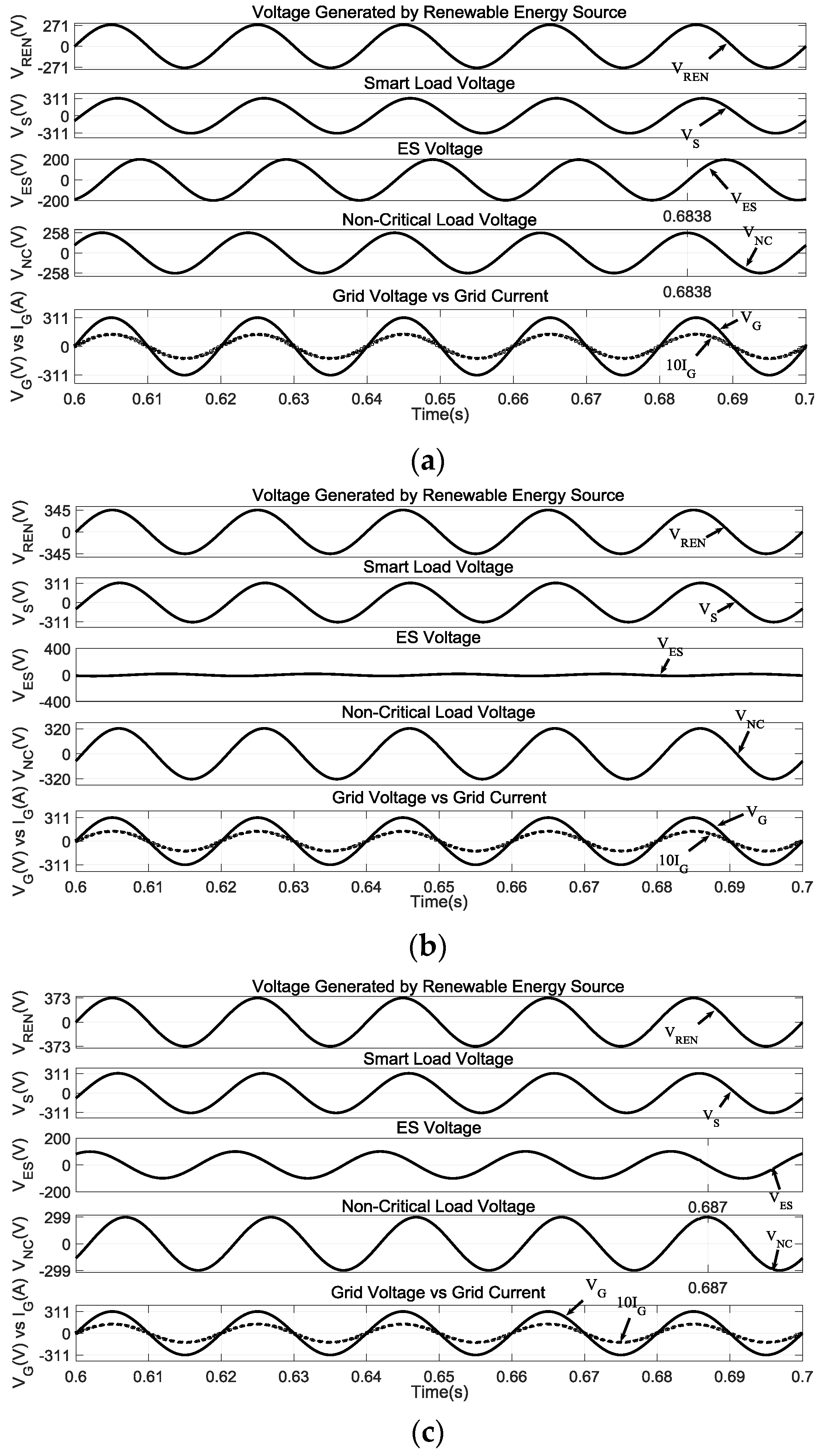
5.1. Grid-Connected CL

In the first situation, the circuit under investigation is that of Figure 4a, with the turn ratios of the transformer set at 11:15:11. Besides the ES control, the diagram of Figure 4b is implemented in the simulation program for the control of the grid-connected inverter. The simulation results are shown in Figure 6a–c, where the rms value of the grid voltage is fixed at 220 V for all the three operating modes: capacitive, resistive and inductive. The first four quantities plotted in each figure are vREN, vS, vES, and vNC, where vS coincides with vC. In the last channel, two waveforms are plotted together: the grid voltage and current, the latter one being scaled-up of 10 times to trace the two quantities in the same figure so as to facilitate their cross evaluation. In Figure 6a, VREN is set at 198 V and the SL voltage is regulated at 220 V. It is seen that vNC leads vES by 90°, which means that ES operates in capacitive mode. The resulting rms value of the grid current is 9.3 A, which is just the expected value. Besides, the zero crossings of the grid voltage coincide with those of the current, which means that the power sent to grid is purely active. The waveforms of vG, iG and vS are almost equal in Figure 6b,c whilst VREN is changed to 244.5 V and 264 V, respectively. The only differences are that ES operates in resistive mode in Figure 6b and inductive mode in Figure 6c. Obviously, in all the operating modes the power drawn by CL is transferred to the grid completely.

5.2. CL of Mixed Types

In the second situation, the circuit under investigation is that of Figure 5b since it is assumed that the line frequency fluctuates within an acceptable range. According to Equation (5) and parameters in Table 1, Z22 is equal to 22 Ω. Reference value of IG is set at 5 A.
Figure 7a–d plot the various circuit quantities. Differently from Figure 6, Figure 7a–c contain the voltage of CL connected to the fourth port of the transformer and rated at lower voltage (e.g., 110 V). For an easy reading of the results, the ES voltage vES and the NCL voltage vNC are shown in the fourth channel, the dashed trace being vES. In the fifth channel, the dashed trace is the grid voltage scaled down of 0.2 and the solid trace is the grid-injected current.
Figure 7a–c show that ES operates in capacitive, resistive and inductive modes as VREN increases. Meanwhile, the rms voltages of the SL and CL are regulated at the settled values of 220 V and 110 V, respectively. It can be also observed from the figures that the power injected into the grid is purely active and that the resulting IG is 5 A, which is the settled value.
To further verify the advantages of the proposed topology, transient responses are also checked when the user shuts down Z22 and sends the power to grid. With reference to Figure 7d, VREN is set at 267 V and ES operates initially in inductive mode, which can be deduced from the fact that vNC is lagging vES. The power PC in Z22 and the power Pgrid sent to the grid are given in the second and third channels. Before 0.6 s, the voltage across Z22 is regulated at 110 V and PC is 550 W. Pure active power is injected into the grid and IG is regulated at 5 A, which means that Pgrid is also 550 W. At 0.6 s, Z22 is suddenly disconnected and the control system is instructed to keep constant the total power absorbed by the line, i.e., 1100 W. Therefore, the control system updates the reference of IG from 5 A to 10 A. This is evident from the traces in the third and fourth channels of Figure 7d; they respectively show that: (i) Pgrid changes from 550 W to 1100 W after 0.6 s; and (ii) the rms value of line current changes from 5 A to 10 A. To sum up the simulation results, the fully-isolated ES topologies demonstrate their capabilities of being effective for new application situations.

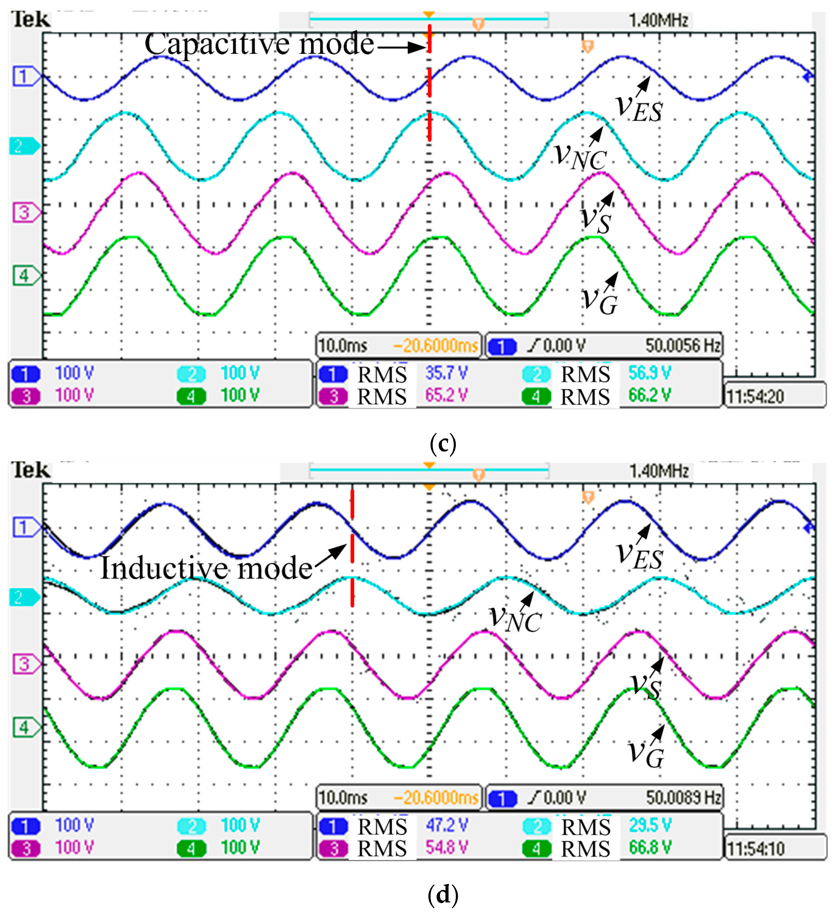
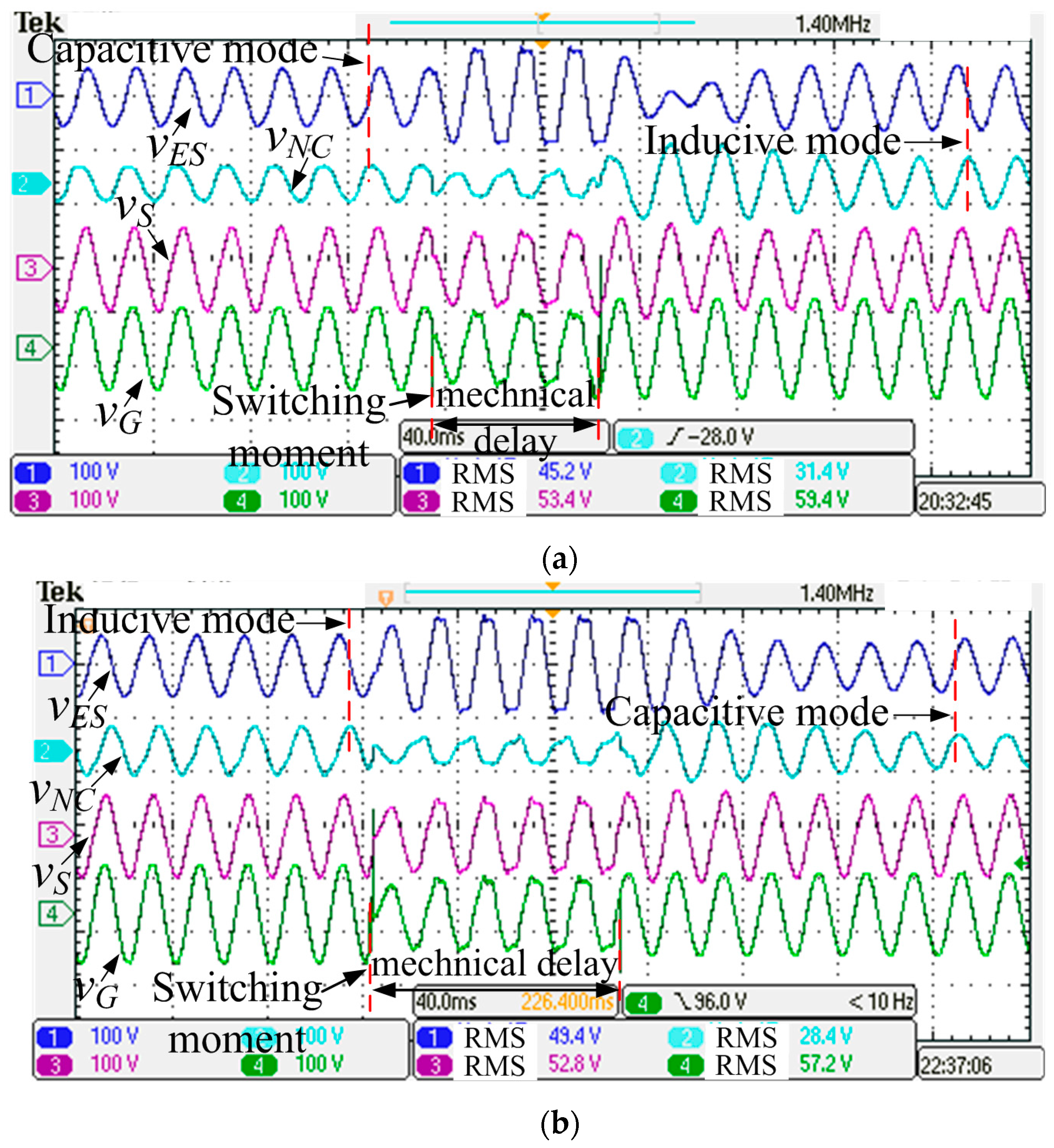
6. Experimental Results

This Section reports and discusses the experimental studies conducted on the fully isolated ES topologies. To this purpose, a prototype setup has been built. Its parameters are scaled down from the ones used for simulations; otherwise the power would have been too large for the activities to be safely executed in the lab. Moreover, by accounting for the lab arrangements, only the standard ES operating modes have been tested. Transient responses have been also tested. Parameters for simulations are shown in Table 2.

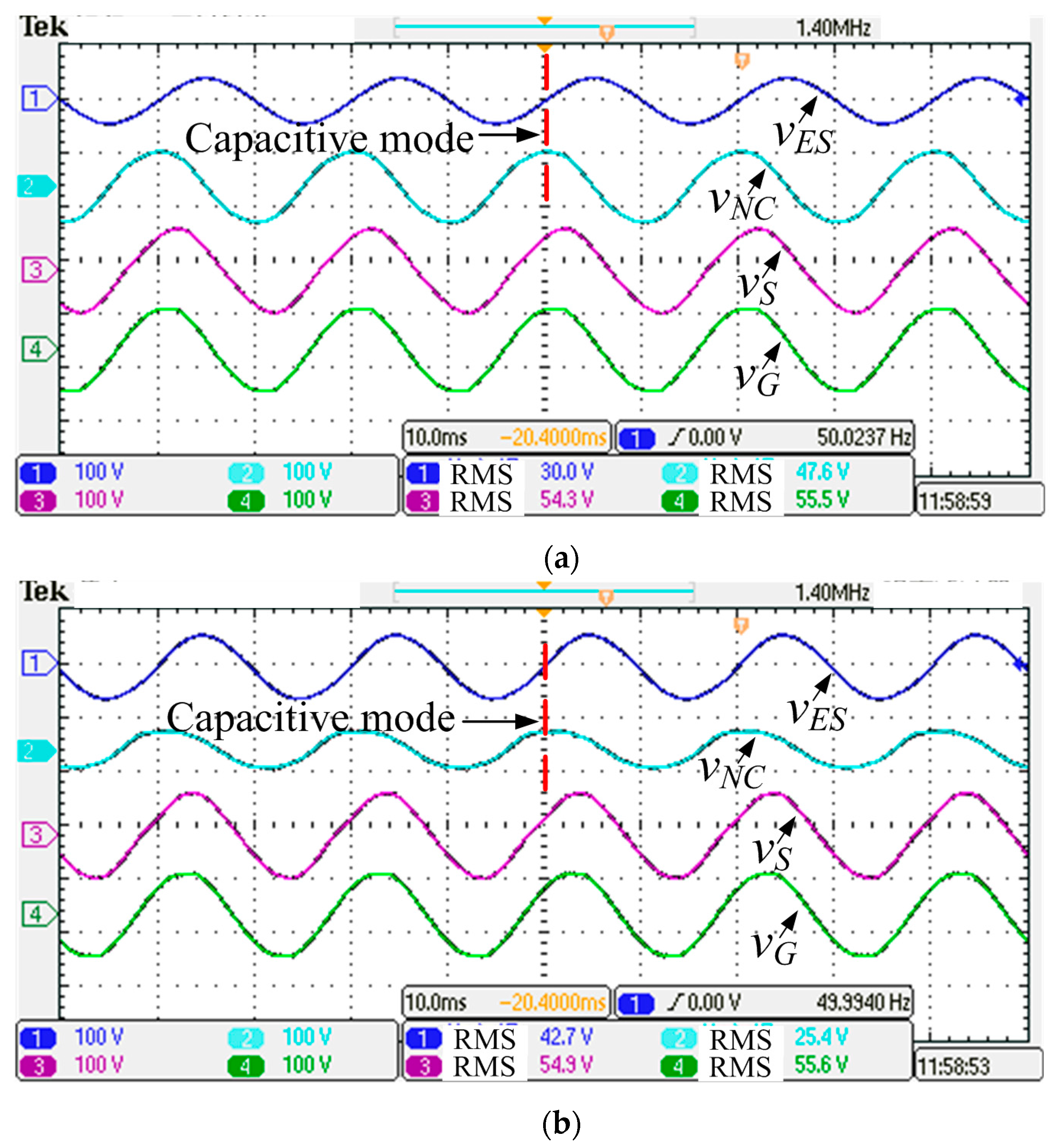
6.1. Fully Isolated TPT-Based ES Setup Test

The fully isolated ES setup with TPT is tested here. The setup has the schematics of Figure 2a and TPT has turn ratios of 1:1:1. To simplify driving of the tests and—at the same time—to make evident the impact of ES on the equipment behavior, S is a one-throw switch; on account of the values used for the circuitry component, no any oscillation arises when S is open and the capacitor remains in series with NCL. The measured waveforms when ES operates in capacitive and inductive modes are reported in Figure 8a–d. In each screen shot, four channels are recorded, namely the ES, NCL, CL and line voltages, respectively, from top to bottom.
Waveforms when switch S in Figure 2a is open are given in Figure 8a–c. They show that the ES, NCL and CL voltages increase as the line voltage increases. It is also observed that the NCL voltage in channel 2 always leads the ES voltage, displayed in channel 1, by 90°. The reason is that the current through NCL is in phase with its voltage because NCL is a pure resistor. This current also flows through the capacitor so that it always leads its voltage by 90°.
Waveforms when switch S is closed, i.e., when ES is activated, are shown in Figure 8b,d. Substantial changes can be seen by the comparison between Figure 8a and Figure 8b. When VG is around 55.5 V, the CL voltage is 54.3 V in the third channel of Figure 8a while its value is 54.9 V in the same channel of Figure 8b. Substantial changes can also be observed in the rms values of VES and VNC, even if vES still lags vNC by 90°, meaning that ES operates in capacitive mode. Similar considerations stem out from the comparison between Figure 8c and Figure 8d. The CL voltage is 65.2 V in Figure 8c while it is 54.8 V in Figure 8d, with ES that operates in inductive mode as one can recognize from the fact that vES leads vNC by 90°.
Transient responses are reported in Figure 9 and illustrate the dynamic performance of the setup. As there is no programmable source in the lab, two variacs were used and switched by a monopole double-throw switch to get the responses in Figure 9a,b.
The switch has three states, namely: (i) connected to variac #1; (ii) disconnected; and (iii) connected to variac #2. A delay exists from the time of flipping the switch to the establishment of the new state, which can be ignored.
In Figure 9a, variac #1 supplies the setup with a voltage lower than the operating value of 55 V. Voltage vNC leads vES by 90° and ES operates initially in capacitive mode. After vREN is connected to variac #2 with output voltage higher than 55 V, vNC starts to lag vES by 90° and ES operates in inductive mode. It is observed in channel 3 that the CL voltage at steady state is regulated at 55 V before and after the switching.
The situation is opposite in Figure 9b. At first, VREN is higher than 55 V and ES operates in inductive mode. When the line voltage is switched at a voltage lower than 55 V, after a time of about 75 ms due to the switch delay, ES enters in capacitive mode. The experimental results demonstrate the excellent dynamic performance of the fully isolated TPT-based ES setup.

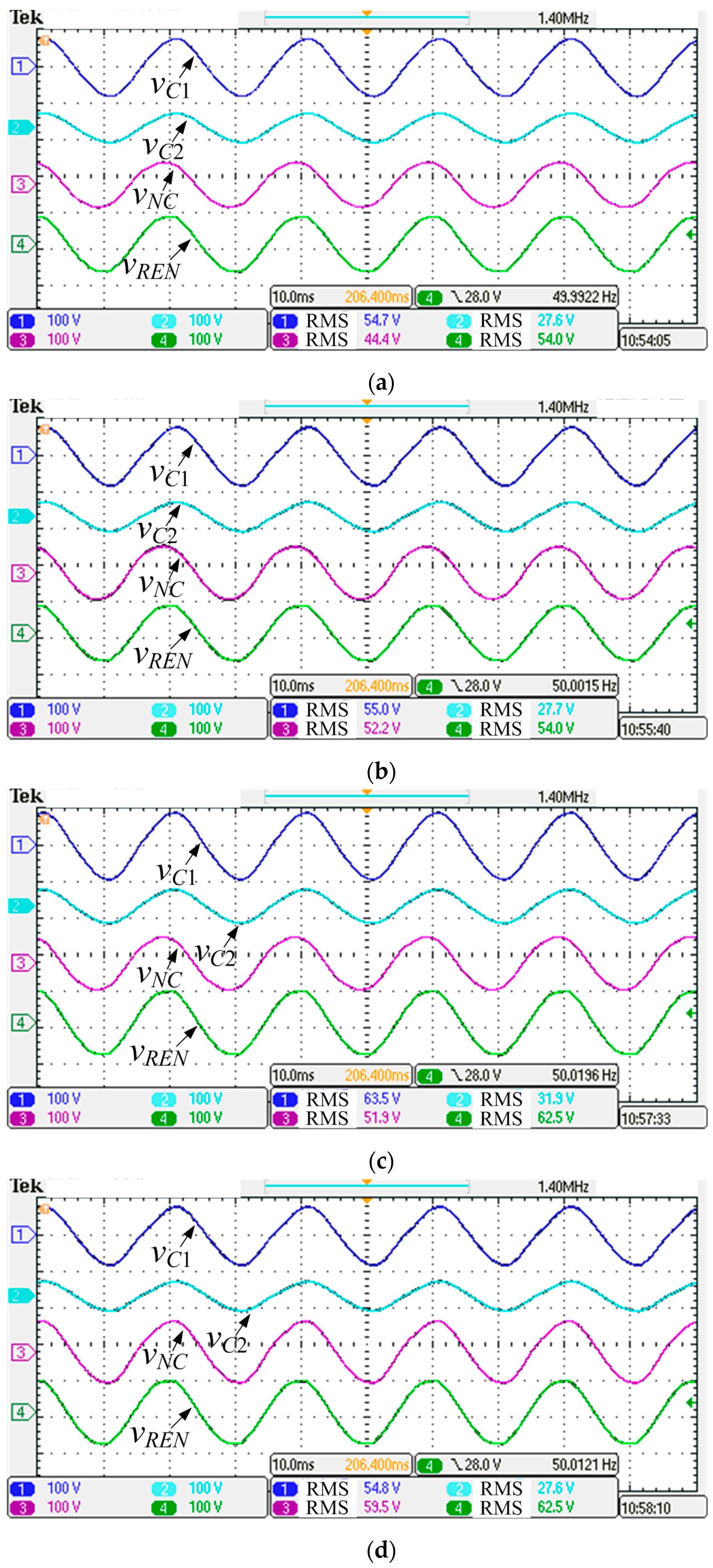
6.2. Fully Isolated FPT-Based ES Setup Test

The fully isolated ES setup with FTF is finally tested. The setup has the scheme of Figure 2b and FPT has turn ratio of 2:2:2:1. The measured waveforms here reported are vC1 (voltage across CL #1), vC2 (voltage across CL #2), vNC (voltage across NCL), and vREN (line voltage), before and after the ES activation. They are given in the screenshots of Figure 10a–d. The stabilization requirements for VC1 and VC2 are of 55 V and 27.5 V, respectively.
In Figure 10a, with VREN equal to 54 V and switch S open, the rms values of VC1, VC2 and VNC are 54.7 V, 27.6 V and 44.4 V, respectively, and the stabilization requirements for VC1 and VC2 are not met. In Figure 10b, with switch S closed, ES is activated and the rms values of VC1, VC2 and VNC change to 55 V, 27.7 V and 52.2 V, respectively. In Figure 10c, with VREN equal to 62.5 V and switch S closed, the rms values of VC1, VC2 and VNC are 63.5 V, 31.9 V and 51.9 V, respectively, and again the stabilization requirements for VC1 and VC2 are not met. In Figure 10d, with switch S closed, ES is activated and the values of VC1, VC2 and VNC change to 54.8 V, 27.6 V and 59.5 V, respectively. It turns out from the experiments that, in spite of the line voltage fluctuations, ES is able to regulate well the voltages across CLs at the settled values, thus validating the design of the fully isolated FPT-based ES setup.

7. Conclusions

The concept of integrating ESs and MPTs has been proposed as an effective solution to comply with the voltage requirements of CLs when supplied by AC microgrids with prevalent RES power generation and, at the same time, to extend the applicative potentials of the original ES equipment.
The fully isolated ES topologies obtained by implementing this concept of integrating ESs and MPTs, appear as the AC counterpart of the dc-dc MPCs without their inconveniences of needing a power converter at each port and an intricate control. Indeed, as expounded in the paper, voltage magnitude stabilization at each port is achieved by regulating the transformer flux at the MPT port connected to ES and the ES equipment can be controlled with the existing δ technique.
Some applications of fully isolated ES topologies with TPT and FPT have been examined to explain the proposed concept. Possible applications and impacts on smart grid development and especially on micro grids are discussed. Besides offering a safer environment for the users, the opportunity of these topologies in selling power to the grid has been pointed out. In particular, in one of the applications examined, it has been demonstrated that: (i) the user can decide the portion of power to be used for self-consumption with respect to the power sold to the grid; (ii) the quality of the power sold to the grid is high; and (iii) the change in the power portion is managed in a smooth way. Simulations and experiments are reported that validate the applicative potentials of the integrated ES-MPT topologies.
A final remark concerns the competitiveness of the proposed solution; undoubtedly, the usage of a transformer increases the cost of the original ES equipment. If the use of the transformer is mandatory as per EN 50438, the additional cost must be supported. In the other cases, the users should balance the cost, space requirements and simplicity of the non-isolated ES-2 topology against safety and the other features offered by the proposed fully-isolated topologies. From a technical perspective, cost reduction by tailoring the design of the transformer to the specific applications is one future research topic.

Acknowledgments

This work was supported by the National Natural Science Foundation of China under project 51320105002.

Author Contributions

Ming Cheng provided guidance and supervision. Qingsong Wang conceived the idea of this paper and performed the simulation and also performed the experiment, wrote the paper. Giuseppe Buja and Ming Cheng revised the manuscript and added their thinking to validate the idea. All authors have equally contributed to the simulation analysis, experiment and result discussions.

Conflicts of Interest

The authors declare no conflict of interest.

References

  1. Guerrero, J.M.; Vasquez, J.C.; Matas, J.; de Vicuna, L.G.; Castilla, M. Hierarchical control of droop-controlled AC and DC microgrids—A general approach toward standardization. IEEE Trans. Ind. Electron. 2011, 58, 158–172. [Google Scholar] [CrossRef]
  2. Cheng, M.; Zhu, Y. The state of the art of wind energy conversion systems and technologies: A review. Energy Convers. Manag. 2014, 88, 332–347. [Google Scholar] [CrossRef]
  3. Han, J.; Solanki, S.K.; Solanki, J. Coordinated predictive control of a wind/battery microgrid system. IEEE J. Emerg. Sel. Top. Power Electron. 2013, 1, 296–305. [Google Scholar] [CrossRef]
  4. Kienzle, F.; Ahcin, P.; Andersson, G. Valuing investments in multi energy conversion, storage, and demand-side management systems under uncertainty. IEEE Trans. Sustain. Energy 2011, 2, 194–202. [Google Scholar] [CrossRef]
  5. Krishnaswami, H.; Mohan, N. Three-port series-resonant DC–DC converter to interface renewable energy sources with bidirectional load and energy storage ports. IEEE Trans. Power Electron. 2009, 24, 2289–2297. [Google Scholar] [CrossRef]
  6. Chien, L.J.; Chen, C.C.; Chen, J.F.; Hsieh, Y.P. Novel three-port converter with high-voltage gain. IEEE Trans. Power Electron. 2014, 29, 4693–4703. [Google Scholar] [CrossRef]
  7. Strunz, K.; Abbasi, E.; Huu, D.N. DC microgrid for wind and solar power integration. IEEE J. Emerg. Sel. Top. Power Electron. 2014, 2, 115–126. [Google Scholar] [CrossRef]
  8. Hui, S.Y.R.; Lee, C.K.; Wu, F. Electric springs—A new smart grid technology. IEEE Trans. Smart Grid 2012, 3, 1552–1561. [Google Scholar] [CrossRef]
  9. Tan, S.C.; Lee, C.K.; Hui, S.Y.R. General steady-state analysis and control principle of electric springs with active and reactive power compensations. IEEE Trans. Power Electron. 2013, 28, 3958–3969. [Google Scholar] [CrossRef]
  10. Lee, C.K.; Hui, S.Y.R. Input AC Voltage Control Bi-Directional Power Converters. U.S. Patent Application 13/907,350, 5 December 2013. [Google Scholar]
  11. Yan, S.; Tan, S.C.; Lee, C.K.; Hui, S.Y.R. Electric springs for reducing power imbalance in three-phase power systems. IEEE Trans. Power Electron. 2015, 30, 3601–3609. [Google Scholar] [CrossRef]
  12. Krishnanand, K.R.; Hasani, S.M.F.; Soni, J.; Panda, S.K. Neutral current mitigation using controlled electric springs connected to microgrids within built environment. In Proceedings of the IEEE Energy Conversion Congress and Exposition (ECCE), Pittsburgh, PA, USA, 14–18 September 2014; pp. 2947–2951.
  13. Wang, Q.; Cheng, M.; Chen, Z.; Wang, Z. Steady-state analysis of electric springs with a novel δ control. IEEE Trans. Power Electron. 2015, 30, 7159–7169. [Google Scholar] [CrossRef]
  14. Wang, Q.; Cheng, M.; Jiang, Y. A novel controller of electric springs based on Bode diagram optimization. J. Power Electron. 2016, 4, 1396–1406. [Google Scholar] [CrossRef]
  15. Chen, X.; Hou, Y.; Tan, S.C.; Lee, C.K.; Hui, S.Y.R. Mitigating voltage and frequency fluctuation in microgrids using electric springs. IEEE Trans. Smart Grid 2015, 6, 508–515. [Google Scholar] [CrossRef]
  16. Mok, K.T.; Tan, S.C.; Hui, S.Y.R. Decoupled power angle and voltage control of electric springs. IEEE Trans. Power Electron. 2016, 31, 1216–1229. [Google Scholar] [CrossRef]
  17. Wang, W.; Yan, L.J.; Zeng, X.J.; Fan, B.; Guerrero, J.M. Principle and design of a single-phase inverter based grounding system for neutral-to-ground voltage compensation in distribution networks. IEEE Trans. Ind. Electron. 2017, 64, 1204–1213. [Google Scholar] [CrossRef]
  18. Luo, X.; Lee, C.K.; Ng, W.M.; Yan, S.; Chaudhuri, B.; Hui, S.Y.R. Use of adaptive thermal storage system as smart load for voltage control and demand response. IEEE Trans. Smart Grid. 2016. [Google Scholar] [CrossRef]
  19. Mok, K.T.; Yang, T.B.; Tan, S.C.; Hui, S.Y.R. Distributed grid voltage and utility frequency stabilization via shunt-type electric springs. In Proceedings of the IEEE Energy Conversion Congress and Exposition (ECCE), Montreal, QC, Canada, 20–24 September 2015; pp. 3774–3779.
  20. Moretti, M.; Djomo, S.N.; Azadi, H.; May, K.; Vos, K.D.; Passel, S.V.; Witters, N. A systematic review of environmental and economic impacts of smart grids. Renew. Sustain. Energy Rev. 2017, 68, 888–898. [Google Scholar] [CrossRef]
  21. Fera, M.; Macchiaroli, R.; Iannone, R.; Miranda, S.; Riemma, S. Economic evaluation model for the energy demand response. Energy 2016, 112, 457–468. [Google Scholar] [CrossRef]
  22. Soares, J.; Ghazvini, M.A.F.; Borges, N.; Vale, Z. A stochastic model for energy resources management considering demand response in smart grids. Electr. Power Syst. Res. 2017, 143, 599–610. [Google Scholar] [CrossRef]
  23. Fera, M.; Iannone, R.; Macchiaroli, R.; Miranda, S.; Schiraldi, M.M. Project appraisal for small and medium size wind energy installation: The Italian wind energy policy effects. Energy Policy 2014, 74, 621–631. [Google Scholar] [CrossRef]
  24. Liao, Z.J. The evolution of wind energy policies in China (1995–2014): An analysis based on policy instruments. Renew. Sustain. Energy Rev. 2016, 56, 464–472. [Google Scholar] [CrossRef]
  25. Ayoub, N.; Musharavati, F.; Pokharel, S.; Gabbar, H.A. Risk based life cycle assessment conceptual framework for energy supply systems in large buildings. J. Clean. Prod. 2015, 107, 291–309. [Google Scholar] [CrossRef]
Figure 1. Topology and operation of non-isolated ES. (a) Schematics; (b) Vector diagram for the inductive operating mode.
Energies 10 00193 g001
Figure 2. Integration of ESs with MPTs. (a) With TPT; (b) With FPT.
Energies 10 00193 g002
Figure 3. Equivalent circuits of the fully isolated ES topologies based on (a) TPT with turn ratio 1:1:1; (b) FPT with turn ratio 2:2:2:1.
Energies 10 00193 g003
Figure 4. The case of CL connected to the grid. (a) Schematics; (b) Control diagram of the grid-connected inverter.
Energies 10 00193 g004aEnergies 10 00193 g004b
Figure 5. CLs of mixed types. (a) TPT with turn ratio 1:1:1, frequency of CL fluctuates as vREN; (b) FPT with turn ratio 2:2:2:1, frequency of CL fluctuates as vREN; (c) TPT with turn ratio 1:1:1, frequency of CL is the same as the grid; (d) FPT with turn ratio 2:2:2:2, frequency of CL is fixed.
Energies 10 00193 g005aEnergies 10 00193 g005b
Figure 6. Simulation results for grid-connected CL with fully isolated TPT-based ES topology. (a) Capacitive mode @VREN = 198 V; (b) Resistive mode @ VREN = 244.5 V; (c) Inductive mode @ VREN = 264 V.
Energies 10 00193 g006
Figure 7. Simulation results for CLs of mixed types with fully isolated FPT-based ES topology. (a) Capacitive mode with VREN = 198 V; (b) Resistive mode with VREN = 244.5 V; (c) Inductive mode with VREN = 264 V; (d) Transient response when Z22 is shut-down and all the power is sent to the grid (VREN = 267 V).
Energies 10 00193 g007aEnergies 10 00193 g007b
Figure 8. Experimental results of the fully isolated ES setup with TPT (100 V/div, 10 ms/div). (a) ES is not activated at VREN = 55.5 V; (b) ES is activated and operates in capacitive mode at VREN = 55.6 V; (c) ES is not activated at VREN = 66.2 V; (d) ES is activated and operates in inductive mode at VREN = 66.8 V.
Energies 10 00193 g008aEnergies 10 00193 g008b
Figure 9. Transient responses of the fully isolated ES topology with TPT (100 V/div, 40 ms/div). (a) From capacitive to inductive mode; (b) From inductive to capacitive mode.
Energies 10 00193 g009
Figure 10. Experimental results of the fully isolated ES setup with FPT (100 V/div, 10 ms/div). (a) ES is not activated at VREN = 54 V; (b) ES is activated at VREN = 54 V; (c) ES is not activated at VREN = 62.5 V; (d) ES is activated at VREN = 62.5 V.
Energies 10 00193 g010
Table 1. Simulation Parameters.
ParametersValuesUnits
Regulated SL voltage (VS)220V
Battery voltage (Vdc)480V
Line resistance (R1)0.1Ω
Line inductance (L1)2.4mH
CL (Z2)44Ω
CL 1 (Z21)88Ω
CL 2 (Z22)22Ω
NCL (Z3)2.2Ω
Inductance of low-pass filter (L)3mHμ
Capacitance of low-pass filter (C)50μF
Turns ratio of the TPT (N1:N2:N3)1:1:11
Turns ratio of the FPT (N1:N2:N3:N4)2:2:2:11
Inductance of low-pass filter (LG)3mH
Grid voltage (VG)110V
Table 2. Experimental Parameters.
ParametersValuesUnits
Regulated SL voltage (VS)55V
Battery voltage (Vdc)180V
Line resistance (R1)5.5Ω
Line inductance (L1)85.4mH
CL (Z2)2000Ω
CL 1 (Z21)4000Ω
CL 2 (Z22)1000Ω
NCL (Z3)100Ω
Inductance of low-pass filter (L)3mH
Capacitance of low-pass filter (C)50μF

