Article

A Novel Electric Vehicle Powertrain System Supporting Multi-Path Power Flows: Its Architecture, Parameter Determination and System Simulation

1
Department of Electrical and Electronic Engineering, Southern University of Science and Technology, Shenzhen 518055, China
2
Shenzhen Key Laboratory of Electric Direct Drive Technology, Shenzhen 518055, China
*
Author to whom correspondence should be addressed.
Energies 2017, 10(2), 216; https://doi.org/10.3390/en10020216
Submission received: 10 November 2016 / Accepted: 6 February 2017 / Published: 13 February 2017

Abstract

:
In this paper, a novel electric vehicle powertrain system is proposed. In the system, a coaxial magnetic gear (CMG), an electromagnetic clutch, a lock, and two electric machines (EMs) are adopted to achieve the power-split by controlling the states of the clutch and the lock, which enables electric vehicles (EVs) to work in four operation modes. The configuration, power flow paths and operation modes are depicted in detail. A dynamic model is established to help determine the parameters and build simulation models. The simple control strategy is adopted to achieve flexible power-splits. How to determine the relevant parameters to meet the drive requirements in the powertrain system is also elaborated. A dynamic simulation using MATLAB/Simulink is performed to take into account the control strategy and New European Drive Cycle. Finally, the simulation results demonstrate, in theory, the rationality of the determined parameters and the feasibility of the operation modes as well as the control strategy.

1. Introduction

Electric vehicles (EVs) have attracted increasing attention all over the world due to the serious concerns of the energy crisis and air pollution [1,2,3]. Generally, EVs can be classified into three types, namely, battery electric vehicles (BEVs), hybrid electric vehicles (HEVs), and fuel cell electric vehicles (FCEVs) [4,5]. Compared with FCEVs, BEVs have the advantages of relatively low cost and mature technology. Moreover, unlike HEVs, BEVs can achieve zero emissions. Therefore, vigorously developing BEVs is considered the best solution to promote electric transportation at this time. Especially in China, the central government has identified BEVs as one of the most promising directions for the automotive industry.
Traditionally, a BEV has a relatively simple architecture which mainly consists of one electric machine (EM), one transmission, and battery packs. The EM obtaining the energy from the battery propels the BEV through the transmission. However, there still exist the following shortcomings in the traditional BEVs: (1) Since the BEV is driven by the EM alone and it is also required to work in a wide range of velocities [6], it is bound to increase the maximum power and speed of the EM when we design or choose the EM, which will create difficulties in the design of the BEV; (2) it is rather obvious that there is only one power flow path. As far as regenerative braking is concerned, the instantaneous power from braking may cause potential damage to the batteries and reduce the battery life. In order to solve the problem in the energy feedback, researchers have put forward hybrid energy storage systems, such as the flywheel hybrid energy storage system [7,8] and the ultra-capacitor hybrid energy storage system [9,10]. Although the engagement of flywheels or ultra-capacitors will make the structure of BEVs more complex, they are very effective.
In HEVs, in order to improve fuel economy and reduce emission, the powertrain system with a power-split are widely adopted [11,12,13]. In addition, one famous powertrain system is the Toyota Prius, which consists of two EMs and a single planetary gear. By controlling the speeds and torques of the two EMs, the Toyota Prius system can achieve multi-path power flows to make the internal-combustion engine (ICE) operate in a highly efficient way [14]. Based on the Toyota Prius system, reference [15] has designed and analyzed a powertrain system with a coaxial magnetic gear (CMG). The novelty of the system is that the coaxial magnetic gear replaces the planetary gear in the Toyota Prius system, which can eliminate the nuisance of gears, such as noise, vibration, maintenance, and so on. Put simply, the powertrain system using a planetary gear or CMG integrated with two EMs is effective at achieving multi-path power flows in HEVs.
Inspired by the system supporting multi-path power flows in HEVs and flywheel energy storage systems in EVs, this paper aims to propose a novel electric vehicle powertrain system in order to solve the above mentioned problems in traditional BEVs. It is mainly composed of a CMG [16,17], an electromagnetic clutch, a lock, and two EMs. In addition, the CMG integrates one of the EMs, which makes the configuration more compact [18]. From a functional point of view, the system possesses the following characteristics: (1) It can be propelled by the two EMs simultaneously, one is the main drive motor, and the other is the auxiliary drive motor with high speed, so the required driving power can be shared by the two EMs. For the main drive motor, the required operating speed range becomes much narrower, and this is conducive to motor design; (2) The auxiliary drive motor can also work as a flywheel storage device when necessary, which is capable of buffering the energy from regenerative braking, so as to protect the battery; (3) The system integrates a CMG for power-split. Compared with the mechanical gears, the CMG is a magnetic transmission device which can achieve non-contact torque transmission and speed variation [19]. It has several advantages, such as reducing noise and vibration, being maintenance free, having overload protection, etc. [20,21]; (4) By controlling the states of the clutch and the lock, the CMG enables the powertrain system to work in four operation modes and fulfill multi-path power flows. The main contribution of this paper is to propose a novel powertrain system supporting multi-path power flows for BEVs to protect the battery when braking with high instantaneous power and to determine the parameters of the proposed powertrain system.
The paper is organized as follows: In Section 2, the detailed configuration of the powertrain system is depicted and the operation modes are elaborated. In Section 3, a dynamic model of the powertrain system is established. Then, the parameters of the powertrain system are determined in Section 4. Next, Section 5 is devoted to the verification of operation modes in Section 2 and the rationality of the parameters in Section 4. Finally, conclusions are drawn in Section 6.

2. Powertrain Description

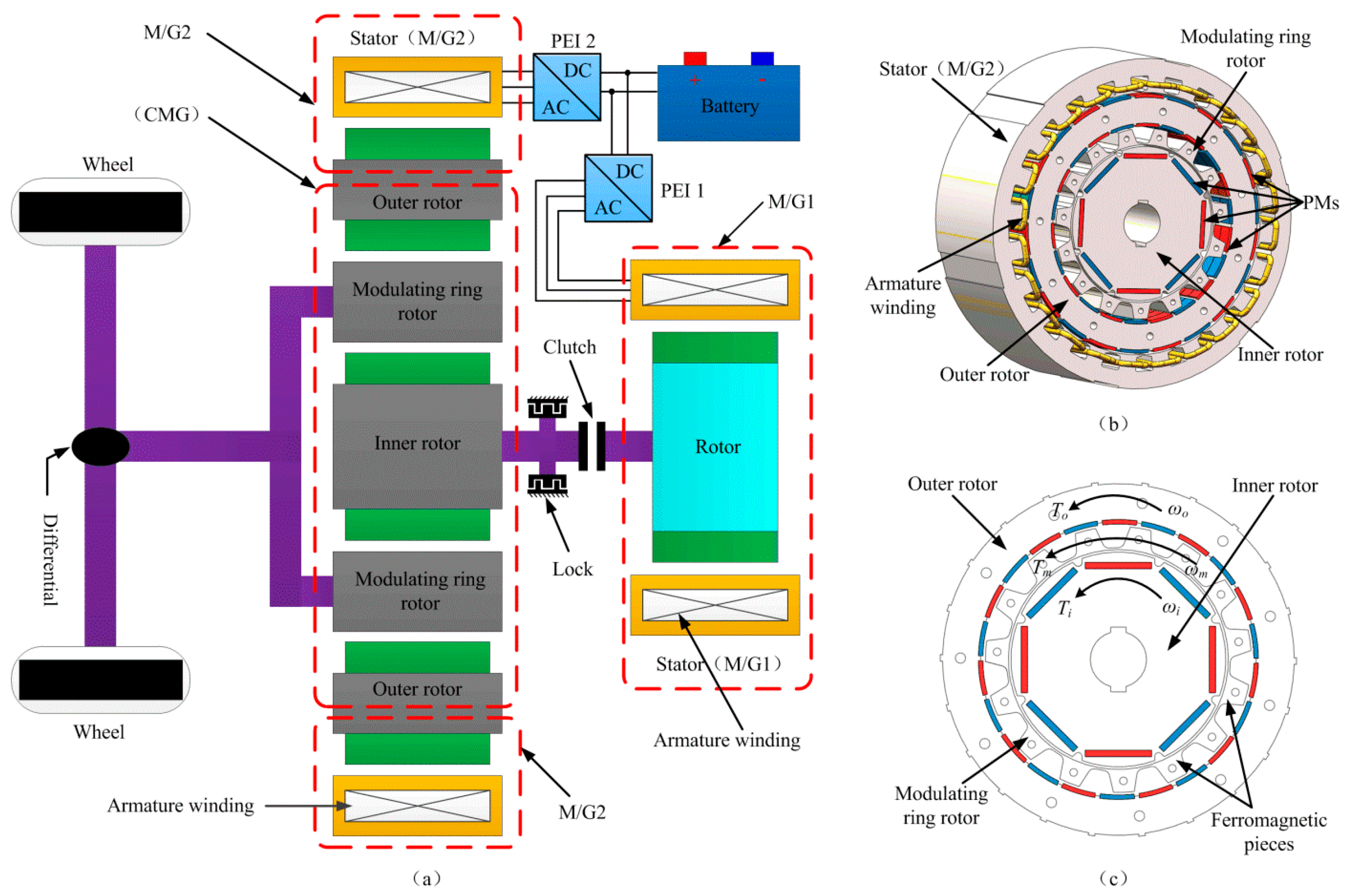
Figure 1a depicts the configuration of the proposed powertrain system. It mainly consists of a coaxial magnetic gear (CMG), two EMs (M/G1 and M/G2), two power electronic inverters (PEI 1 and PEI 2), an electromagnetic clutch, a lock, and battery packs. The CMG is the key component in the powertrain system, which plays the role of coupling multiple shafts to implement a power-split. The CMG and the M/G2 constitute an integrated magnetic gear permanent magnet (IMG-PM) machine, as shown in Figure 1b. The IMG-PM machine is characterized by the rotor of M/G2 and the outer rotor of CMG sharing a rotor, and permanent magnets (PMs) are installed on both sides of the rotor. The modulating ring rotor is rigidly connected to the final driveline, which transmits the force/torque to the wheels via differential and shafts. The inner rotor is connected to the rotor of M/G1 through an electromagnetic clutch and a shaft, and a lock is mounted on the shaft. The stator windings of M/G1 and M/G2 are connected to the battery through PEI 1 and PEI 2, respectively.
Figure 1c shows the topology of the CMG. It can be seen that the CMG is composed of three rotational components, namely, inner rotor, outer rotor, and modulating ring rotor. There are some PMs on both the inner rotor and outer rotor, and the pole-pair numbers (PPNs) of inner rotor and outer rotor are p i and p o , respectively. The modulating ring rotor consists of a certain number of ferromagnetic pieces, the numbers of which are N m . In order to ensure the normal operation of the CMG, N m is governed by the sum of p i and p o [22,23].
As shown in Figure 1c, the positive direction of the torque and the rotational speed is specified in the counterclockwise direction. The values T i , T o , and T m are the permanent magnetic torques provided by the inner rotor, the outer rotor, and the modulating ring rotor, respectively. The values ω i , ω o , and ω m correspond to the rotational speeds of the inner rotor, the outer rotor, and the modulating ring rotor, respectively. The corresponding speed relationship is governed by [15]:
ω i + G r ω o = ( 1 + G r ) ω m
where G r = p o p i is the so-called gear ratio. 
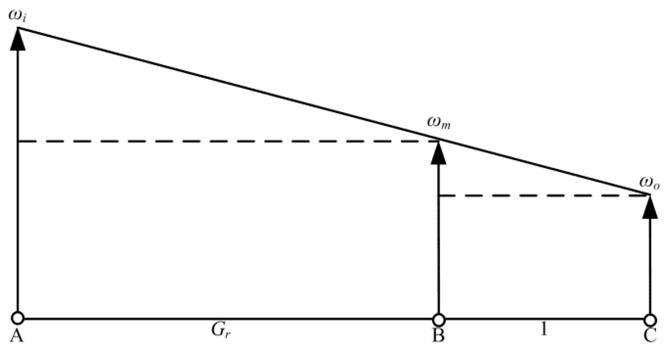
Figure 2 shows the collinear speed map [24], which is utilized to analyze the change relationship of rotational speeds in Equation (1).
With the CMG under steady-state conditions and without considering the power losses in CMG, it yields [15]:
T i ω i + T o ω o + T m ω m =   0
T i + T o + T m =   0
It can be obtained from Equations (1) to (3) that the torque constraint relationships are as follows:
T i = 1 1 + G r T m
T o = G r 1 + G r T m
It can be found from Equations (4) and (5) that the direction of T i and T o are always the same, while the direction of them is opposite to that of T m . Moreover, the torques transmitted by CMG are allocated strictly as per the proportion in Equations (4) and (5).
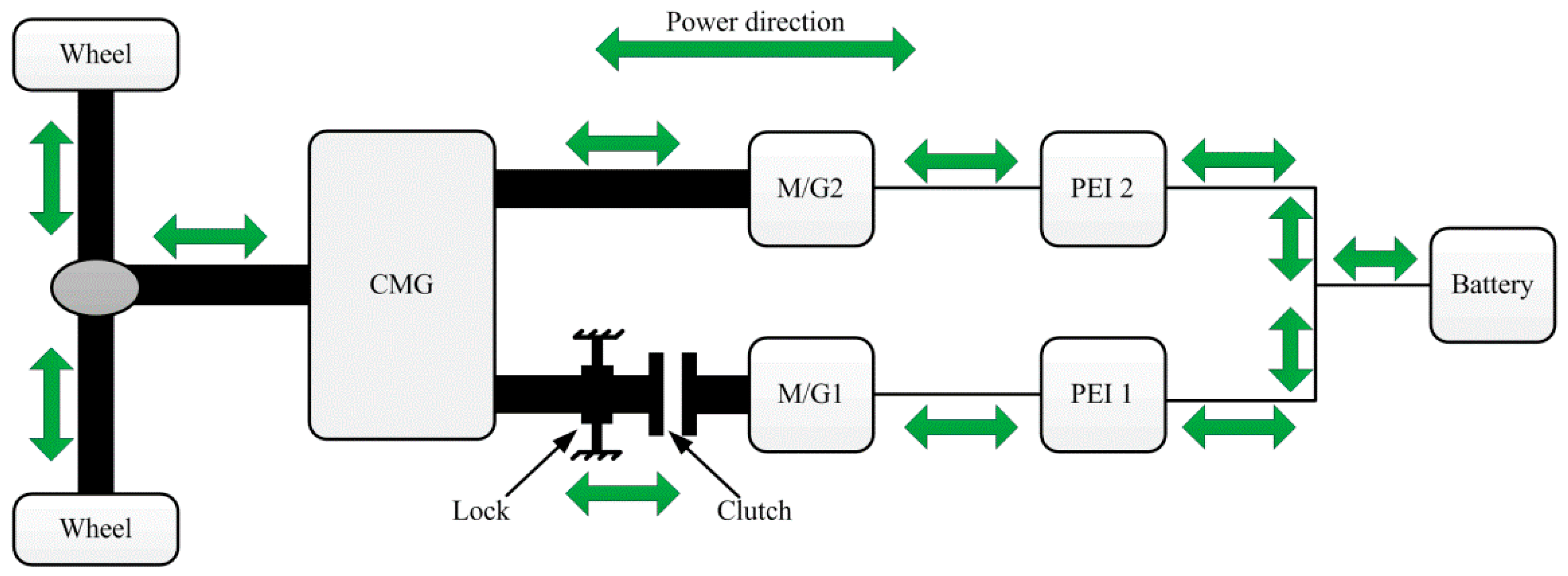
Figure 3 illustrates the power flow paths in the powertrain system. It can be observed that there are diverse power flow paths in the powertrain system and the power in all paths can flow bidirectionally. By switching the states of the M/Gs, controlling the lock and toggling the clutch, the powertrain system can achieve the following operation modes:
Mode 1 (M/G2 driving alone): It means that the powertrain system is driven only by M/G2. When the lock is engaged (locks the inner rotor of CMG), the clutch is disengaged (disconnecting the CMG from M/G1) and M/G1 remains de-energized; the M/G2 works as a motor to deliver its power to the wheels through the CMG and final driveline. In this operation mode, the power flow path is like this: battery → PEI 2 → M/G2 → outer rotor of CMG → modulating ring rotor of CMG → final driveline → wheels.
Mode 2 (Regenerative braking after M/G2 driving alone): This operation mode refers to the time after the M/G2 driving alone mode when the powertrain system needs to brake. At this time, M/G2 is functioning as a generator and M/G2 accepts braking power through the final driveline and CMG. The electric energy from regenerative braking can be either fully used to charge the battery or can be fully used to drive M/G1 which means the electric energy is converted into mechanical energy stored in the rotor of M/G1. In this case, M/G1 can be regarded as a flywheel storage device or can be partly transmitted to battery and partly converted into the mechanical energy of M/G1 by PEI 1.
Mode 3 (M/G1 and M/G2 driving): In this mode, both M/G1 and M/G2 drive the powertrain system. When the lock is released (the inner rotor of CMG can rotate freely) and the clutch is engaged (connecting M/G1 to CMG), both M/G1 and M/G2 work as motors to deliver the power to the wheels through the CMG and final driveline. In this case, the power from the battery can be finally transformed into mechanical energy by the PEI 1, PEI 2, M/G1, M/G2, and CMG.
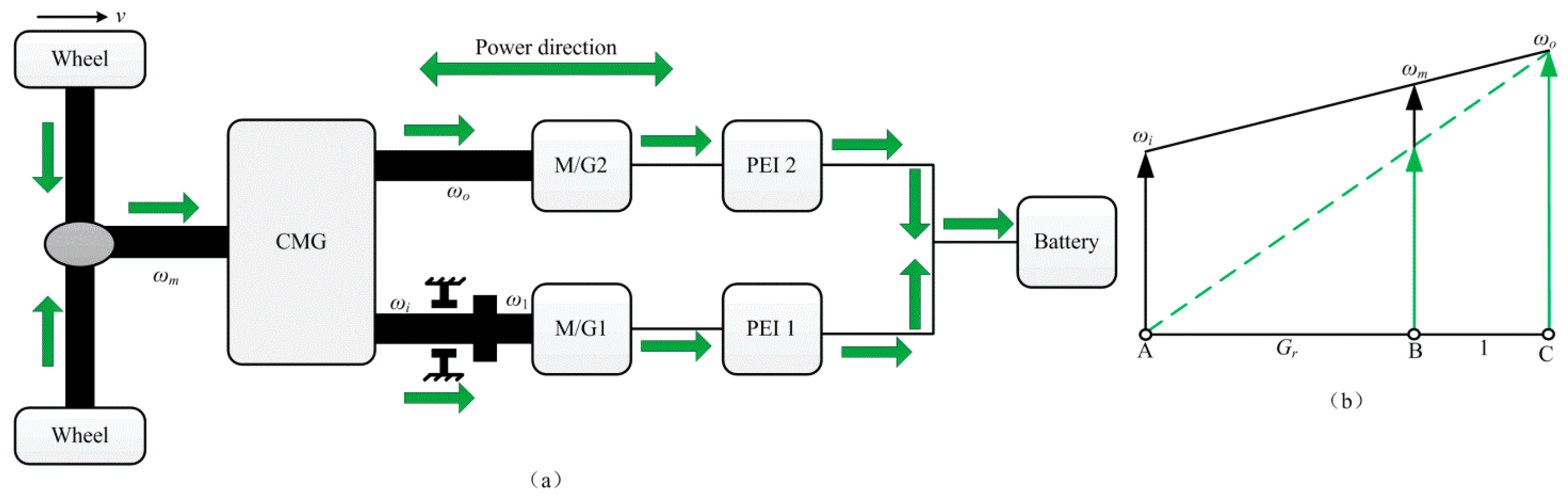
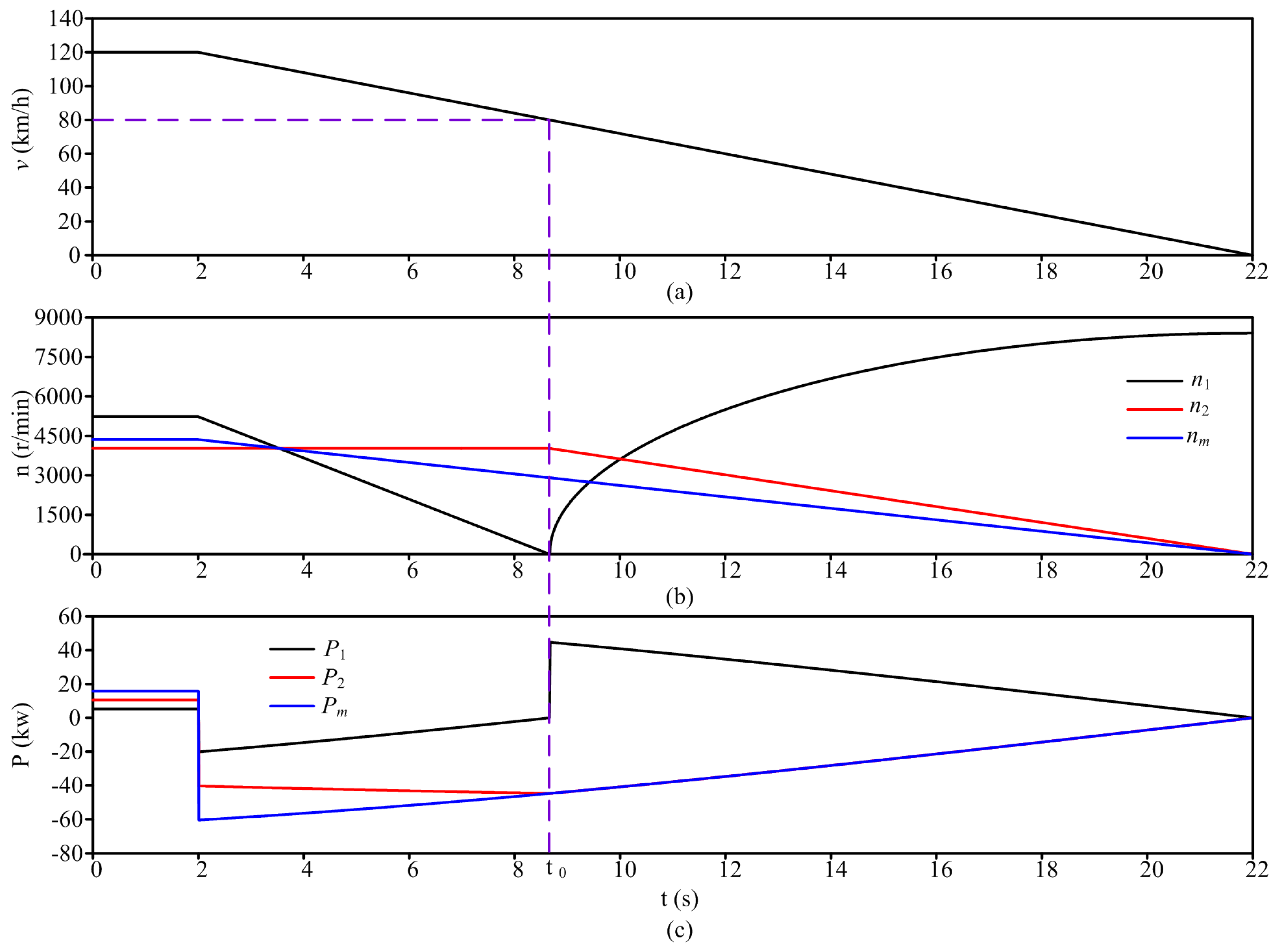
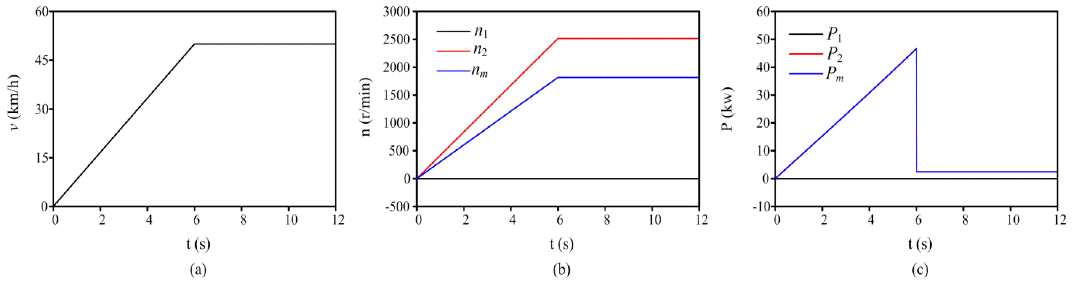
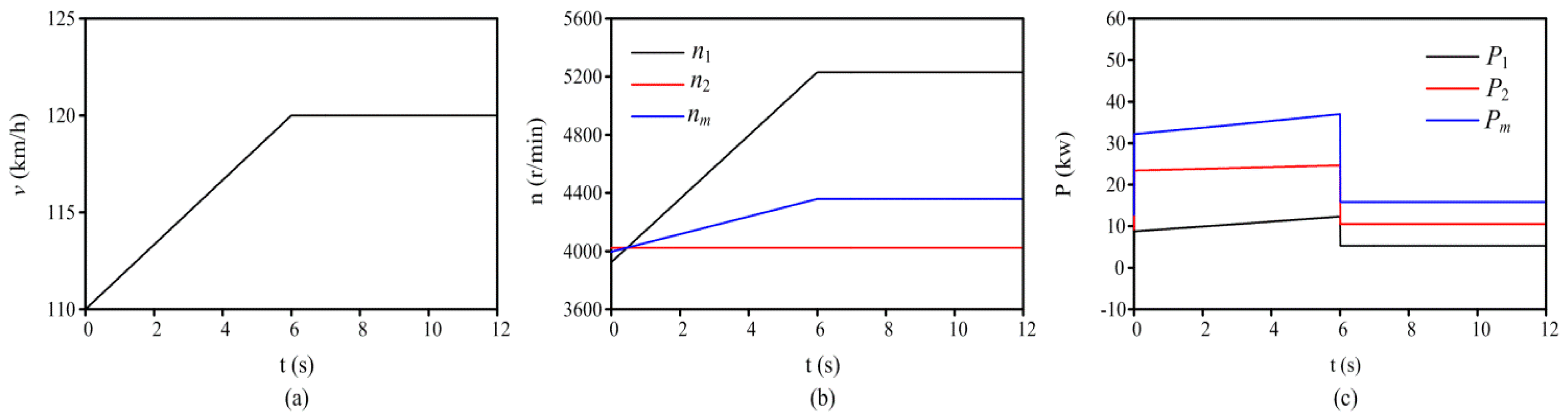
Mode 4 (Regenerative braking after M/G1 and M/G2 driving): This mode refers to the time after the M/G1 and M/G2 driving mode when the powertrain system needs to brake. It can be seen from Figure 4a that the vehicle velocity ( v ) corresponds to that of the modulating ring rotor of CMG; when v slows down, ω m also decreases. In Figure 4a, ω 1 is the speed of M/G1. Because M/G1 and the inner rotor of the CMG have the same rotational speed ( ω 1 = ω i ), to achieve this operation mode, first, keep the rotational speed of M/G2 ( ω o ) unchanged so that M/G1 operates as a generator to reduce the speed of M/G1 ( ω 1 ) and the inner rotor of CMG to zero. When ω 1 and ω i are equal to zero, the clutch will be disengaged and the lock will be engaged. In this process, when ω i and ω 1 are reduced to zero, ω m is not equal to zero, as shown in Figure 4b. After that, if the powertrain system continues to brake, the way to achieve regenerative braking is the same as Mode 2. It is necessary to point out that: (A) throughout the whole process, M/G2 operates as a generator, while M/G1 works as a generator before ω 1 and ω i are equal to zero. After the lock is engaged and the clutch is disengaged, M/G1 may be de-energized or may be functions as a motor; (B) in terms of the power flow paths, before ω 1 and ω i are equal to zero, all the regenerative braking energy is converted into electric energy stored in the battery by M/G1 and M/G2, while after the lock is engaged and the clutch is disengaged, the regenerative braking energy is only converted into electric energy by M/G2, and then, the electric energy can be either fully used to charge the battery, or can be fully converted into mechanical energy of M/G1 by PEI 1, or can be partly transmitted to battery and partly converted into mechanical energy of M/G1 by PEI 1.
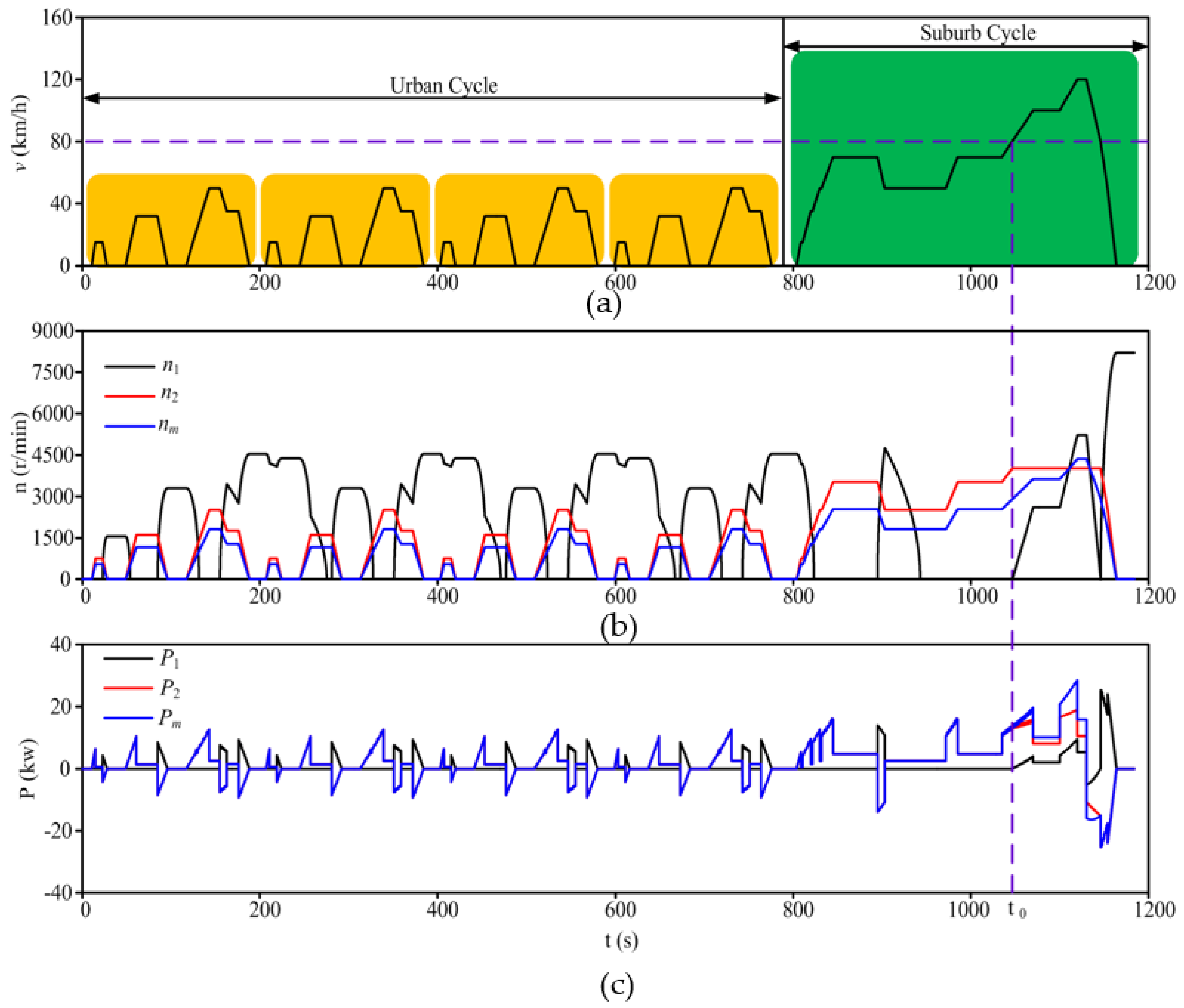
In real operation, how to select the above operation modes mainly depends on the driving cycle and the control strategy.

3. Dynamic Model

The vehicle road load ( F r ) is mainly composed of the rolling resistance ( F f ), the aerodynamic drag force ( F w ), and climbing force ( F i ). These forces can be expressed as follows [25]:
F r = F f + F w + F i
F f = f f M g cos α
F w = 0.5 ρ C D A v 2
F i = M g sin α
where f f is the rolling resistance coefficient, M is the vehicle mass, g is the gravitational acceleration, α is the road slope angle, ρ is the air density, C D is the aerodynamic drag coefficient, and A is the vehicle frontal area.
The vehicle motion equation can be expressed as:
F d F r = δ M d v d t
where F d is the motive force acting on the wheels and δ is a mass correction factor to compensate for the apparent increase in the vehicle’s mass due to the inertia of the onboard rotating mass.
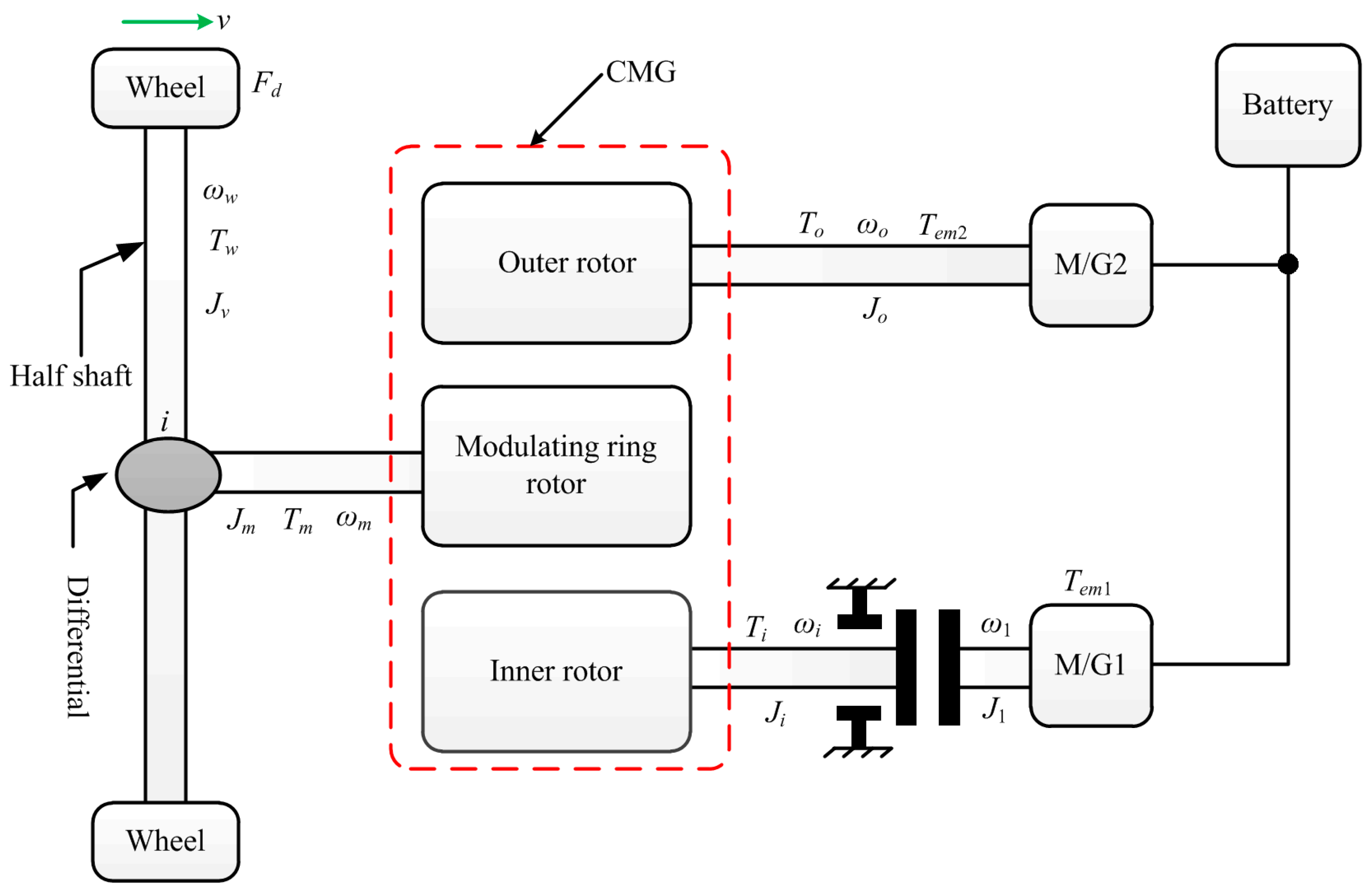
In order to facilitate system modeling, Figure 5 gives a simplified diagram of the powertrain system, in which the relevant parameters of each component are indicated. The required torque of half shaft ( T w ) is given by:
T w = F d R w = ( δ M d v d t + f f M g cos α + 0.5 ρ C D A v 2 + M g sin α ) R w
where R w is tire radius and the relationship between the rotational speed of the half shaft and the vehicle velocity is:
ω w = v R w
For the modulating ring rotor of the CMG, its motion equation can be expressed as:
T m T w i = ( J v i 2 + J m ) d ω m d t
where i is reduction ratio and i = ω m / ω w ; J v , and J m are the moments of inertia of the differential and the half shaft and the modulating ring rotor of CMG, respectively.
For the outer rotor of the CMG, its motion equation can be expressed as:
T o + T e m 2 = J o d ω o d t
where J o is the moment of inertia of the outer rotor of the CMG and T e m 2 is the electromagnetic torque provided by the M/G2.
For the inner rotor of CMG and M/G1, their motion equations have a close relationship with the states of the lock and the clutch. Since both lock and clutch have two states, there exist four cases in theory. However, taking into account the previous analysis of the four operation modes, the motion equations only contain the following two cases:
Case 1: the lock is disengaged and the clutch is engaged, the motion equation can be expressed as:
T i + T e m 1 = ( J i + J 1 ) d ω i d t
where J 1 and J i are the moments of inertia of M/G1 and the inner rotor of CMG, respectively, and T e m 1 is the electromagnetic torque provided by the M/G1. It should be noted that in this case, ω i is equal to ω 1 .
Case 2: the lock is engaged and the clutch is disengaged, the motion equation can be expressed as:
T e m 1 = J 1 d ω 1 d t
It should be noted that in this case, ω i is equal to zero.

4. Parameters Determination

In this section, the parameters of the powertrain system are determined to meet the vehicle performance requirements that we want to achieve, and the vehicle performance requirements are listed in Table 1. The parameters which need to be determined mainly include the vehicle parameters and the parameters of CMG, M/G1, and M/G2. The parameters of CMG, M/G1, and M/G2 must match the vehicle parameters. Thus, first of all, we must determine the vehicle parameters and then carry on the parameter matching. The vehicle basic parameters are listed in Table 2.

4.1. Vehicle Parameters

The vehicle parameters are inclusive of the maximum power ( P t o t a l ) and the maximum driving force ( F d _ max ). Both of them need to be determined according to the maximum velocity, the maximum climbable slope, and the acceleration performance. In addition, P max 1 / F d _ max 1 , P max 2 / F d _ max 2 , and P max 3 / F d _ max 3 correspond to the maximum powers/driving forces based on the performance of the maximum velocity, the maximum climbable slope, and the acceleration, respectively. In the light of [26], the corresponding maximum powers and driving forces are calculated in detail as given below:

4.1.1. P max 1 / F d _ max 1

Only considering the vehicle driving at v max on a road without slope angle, the required power ( P max 1 ) and driving force ( F d _ max 1 ) are calculated by:
P max 1 = ( F f + F w ) v max = ( f f M g + 0.5 ρ C D A v max 2 ) v max
F d _ max 1 = f f M g + 0.5 ρ C D A v max 2
Substituting the relevant data in Table 1 and Table 2 into the above equations, it can be obtained that P max 1 =   28.1 kW and F d _ max 1 =   674.8 N.

4.1.2. P max 2 / F d _ max 2

Supposing that the vehicle is climbing a road with maximum climbable slope ( i 1 _ max ) at a constant speed ( v i ), the required power ( P max 2 ) and driving force ( F d _ max 2 ) in this case are calculated by:
α max = arc tan ( i 1 _ max )
P max 2 = ( F f + F w + F i ) v i = ( f f M g cos α max + 0.5 ρ C D A v i 2 + M g sin α max ) v i
F d _ max 2 = f f M g cos α max + 0.5 ρ C D A v i 2 + M g sin α max
Substituting the relevant data into Equations (19) to (21), it can be obtained that P max 2 =   10.7 kW and F d _ max 2 =   3865.9 N.

4.1.3. P max 3 / F d _ max 3

Ignoring climbing force and assuming that it takes 13 s for the vehicle to accelerate uniformly from 0 to 100 km/h, the required power ( P max 3 ) and driving force ( F d _ max 3 ) in this case are calculated by:
P max 3 = P ( t ) | t = T = δ M v t 2 T + f f M g v t + 0.5 ρ C D A v t 3
F d _ max 3 = δ M v t T + f f M g + 0.5 ρ C D A v t 2
Similarly, it can be obtained that P max 3 =   89.2 kW and F d _ max 3 =   3211.3 N.
The calculation results of the maximum powers and driving forces are summarized in Table 3.
In order to achieve the indices in Table 1, P t o t a l and F d _ max must satisfy the following formulas:
P t o t a l max ( P max 1 , P max 2 , P max 3 )
F d _ max max ( F d _ max 1 , F d _ max 2 , F d _ max 3 )
Finally, taking into account the margin of 3%, we can determine that P t o t a l and F d _ max are 92 kW and 3982 N, respectively. Meanwhile, it can be obtained that the required maximum torque of the half shaft ( T w _ max ) is 1142.8 Nm.

4.2. CMG Parameters

For CMG, the required maximum torques provided by the inner rotor, modulating ring rotor, and outer rotor must match that of the half shaft, which is described by:
T m _ max T w _ max i
T i _ max 1 1 + G r T m _ max
T o _ max G r 1 + G r T m _ max
where T i _ max , T m _ max , and T o _ max are the required maximum torques provided by the inner rotor, modulating ring rotor, and outer rotor, respectively. Eventually, we can determine that T i _ max , T m _ max , and T o _ max are 291 Nm, 81 Nm, and 211 Nm, respectively.

4.3. M/Gs Parameters

The parameters of M/G1 and M/G2 refer to the maximum/rated power, maximum/rated torque, and maximum/rated rotational speed. They not only need to match with the performance requirements, but also meet the control strategy, as shown in Table 4. The powertrain system adopts the control strategy based on vehicle velocity: (1) when 0 v 80 km/h and d v / d t 0 , it will adopt Mode 1. It is worth noting that when vehicle velocity is up to 80 km/h, the rotational speed of M/G2 reaches the maximum; (2) when 80 < v 150 km/h and d v / d t 0 , it will adopt Mode 3. In this case, M/G2 operates at the maximum rotational speed and the adjustment of vehicle velocity depends on the control of the speed of M/G1; (3) when 0 v 80 km/h and d v / d t < 0 , it will adopt Mode 2; (4) when 80 < v 150 km/h and d v / d t < 0 , it will adopt Mode 4.
Therefore, the basic principle of M/G2 parameter determination should be observed as follows: (1) the maximum rotational speed of M/G2 ( n 2 _ max ) is obtained when vehicle velocity is up to 80 km/h; (2) to guarantee the maximum climbable slope, the maximum torque of M/G2 ( T 2 _ max ) should be bigger than that of the outer rotor in the CMG; (3) as per the vehicle performance of acceleration, the maximum power of M/G2 ( P 2 _ max ) can be decided; (4) we set the overload factor of M/G2 ( λ ) to 3. According to the basic principle, the parameters of M/G2 we calculated and chose are listed in Table 5. It can be seen that the ratio of the maximum and the rated rotational speed is about 1.3; it indicates that the operating speed range of M/G2 becomes much narrower by adopting two EMs, which is really conducive to the motor design.
For M/G1, the following principle should be observed in parameter determination: (1) in order to match the required maximum torque provided by the inner rotor of CMG, the maximum torque of M/G1 ( T 1 _ max ) should larger than that of the inner rotor in the CMG; (2) based on the control strategy, the maximum rotational speed of M/G1 ( n 1 _ max ) is decided by the maximum vehicle velocity; (3) we decided that the overload factor of M/G1 be the same as that of M/G2; (4) we set the expansive constant power area coefficient ( β ) to 2.5. The parameters of M/G1 we calculated and chose are shown in Table 6.

5. Simulation and Verification

To verify the operation modes, the powertrain system was modeled and simulated by using MATLAB/Simulink. After that, to evaluate the rationality of the decided parameters, the simulation was also performed based on the New European Driving Cycle (NEDC) by using MATLAB/Simulink. The modeling parameters of the powertrain system are given in Table 7.

5.1. Verification of Operation Modes

5.1.1. Mode 1

Figure 6 shows the simulation results based on the established model. Figure 6a gives the required vehicle velocity, where the vehicle is in a state of uniform acceleration and uniform speed, and the maximum velocity is smaller than 80 km/h. Figure 6b exhibits the rotational speeds of M/G1 ( n 1 ), M/G2 ( n 2 ), and modulating ring rotor ( n m ), where it can be found that the ratio of n 2 and n m is about 1.4 at all times, and M/G1 is kept still. The ratio indicates that the speed of the inner rotor in the CMG is zero and the lock is engaged. Figure 6c shows the powers of M/G1 ( P 1 ), M/G2 ( P 2 ), and modulating ring rotor ( P m ). It can be observed that P 2 and P m are positive and P 1 is zero. Since P 2 is positive, M/G2 works as a motor; since P m is positive, it means the modulating ring rotor transmits energy to the wheels. Judging by n 1 and P 1 , M/G1 doesn’t function in the whole process. It is necessary to point out that due to the neglect of losses in the simulation model, P 2 is equal to P m .

5.1.2. Mode 2

The simulation results based on Mode 2 are presented in Figure 7. Figure 7a shows the required vehicle velocity. The vehicle is driving at a uniform speed from 0 to 6 s and in the state of uniform deceleration from 6 to 12 s, moreover, the maximum velocity is smaller than 80 km/h. Figure 7b exhibits the rotational speeds of M/G1, M/G2, and the modulating ring rotor, where it can be seen that in the whole process, n 2 and n m satisfy the constraint relation in Equation (1), while n 1 is zero from 0 to 6 s; after 6 s, M/G1 is accelerating. Judging by the powers in Figure 7c, 0~6 s: P 2 and P m are positive and P 1 is zero; 6~12 s: P 2 and P m are negative and P 1 is positive. P 2 is negative, which means M/G2 works as a generator; P m is negative, which means the modulating ring rotor recovers energy from wheels; P 1 is positive, which means M/G1 works as a motor. What is more, the value of power is the same among P 1 , P 2 , and P m , which indicates that the energy from braking is all stored in M/G1 in the form of kinetic energy. Therefore, M/G1 plays the role of a flywheel EM.

5.1.3. Mode 3

Figure 8 depicts the simulation results based on Mode 3. It can be observed from Figure 8a that the vehicle velocity is greater than 80 km/h and the vehicle takes 6 s to accelerate from 110 to 120 km/h; during 6~12 s, the vehicle keeps driving at the speed of 120 km/h. As shown in Figure 8b, it can be found that every moment, n 1 , n 2 , and n m satisfy the constraint relationship in Equation (1). The speed of M/G1 is not equal to zero any longer and M/G2 keeps operating at the speed of 4023.5 r/min. Judging by the powers in Figure 8c, P 1 , P 2 , and P m are positive and P m is equal to the sum of P 1 and P 2 , which indicates that in this mode, M/G1 and M/G2 drive the vehicle together.

5.1.4. Mode 4

The simulation results based on Mode 4 are presented in Figure 9. Figure 9a shows the required vehicle velocity. Figure 9b exhibits the rotational speeds of M/G1, M/G2, and the modulating ring rotor. Figure 9c gives the powers of M/G1, M/G2, and the modulating ring rotor. It can be observed from the three Figures that from 0 to 2 s: the vehicle is driving at a uniform speed and the maximum velocity is bigger than 80 km/h; n 1 , n 2 , and n m are kept constant; P 1 , P 2 , and P m are positive and P m is equal to the sum of P 1 and P 2 , which indicates that M/G1 and M/G2 drive the vehicle together. From 2 s to t0: the vehicle velocity decreases linearly to 80 km/h; n 1 is linearly reduced to zero, while M/G2 is operating at the speed of 4023.5 r/min; P 1 , P 2 , and P m are negative and P m is also equal to the sum of P 1 and P 2 , which means that during this time, the energy recovered from braking is convert into electric power stored in the battery through M/G1 and M/G2. From t0 to 22 s: the vehicle continues to slow down; n 2 and n m are reduced linearly, and at every moment, the ratio of n 2 and n m are about 1.4. However, M/G1 is in a state of acceleration; P 2 and P m are negative, P 1 is positive, and the values of P 1 , P 2 , and P m are the same. As a matter of fact, during the time interval, the vehicle is working in Mode 2 and the energy from braking is all stored in M/G1 in the form of kinetic energy. Therefore, M/G1 can be regarded as a flywheel storage device.
In summary, by analyzing the four modes separately, the feasibility of the powertrain system has been verified. In addition, the powertrain system can achieve regenerative braking. What is more, in the process of regenerative braking, M/G1 can function as a flywheel storage device, which is capable of buffering the energy from regenerative braking, so as to protect the battery.

5.2. Simulation Based on New European Driving Cycle

The simulation results based on NEDC by using MATLAB/Simulink are presented in Figure 10. Figure 10a exhibits the NEDC. It is made up of four urban cycles and a suburb cycle, which is one of the main typical conditions of the emission regulations in Europe and China. NEDC time is 1184 s and the maximum velocity is 120 km/h. It can be obtained from the three Figures that due to v 80 km/h, the vehicle operates either in Mode 1 or Mode 2 from 0 to t0, while after t0, the vehicle operates either in Mode 3 or Mode 4. It can be observed from Figure 10b that the maximum speeds of M/G1 and M/G2 are smaller than that listed in Table 5 and Table 6. It can be also seen from Figure 10c that the maximum powers of M/G1 and M/G2 are smaller than that listed in Table 5 and Table 6. Thus, the results prove the rationality of the determined parameters in Table 5 and Table 6. Meanwhile, since the simulation based on NEDC was carried out in continuous operation modes, the simulation results demonstrate, in theory, the feasibility of the operation modes and control strategy again.

6. Conclusions

In this paper, a novel electric vehicle powertrain system has been proposed, which enables the electric vehicles to work in four operation modes and support multi-path power flows. A dynamic model of the powertrain system has been presented. How to determine the relevant parameters in the powertrain system has been elaborated, and the determined parameters indicate that the operating speed range of M/G2 becomes much narrower by adopting two EMs, which means that it is conducive to the design of M/G2. The simulation results obtained by MATLAB/Simulink have demonstrated that the operation modes and the control strategy are feasible in theory; the M/G1 can work as a flywheel storage device when necessary, which is capable of buffering the energy from regenerative braking; the determined parameters are reasonable.

Acknowledgments

This work was supported in part by the National Natural Science Foundation of China under Project 51377158, by the Natural Science Foundation of Guangdong Province under Project 2014A030306034, and by the Science and Technology Innovation Committee of Shenzhen under Projects KQCX20140522151322948, ZDSYS201604291912175, and JCYJ20150529152146473.

Author Contributions

The successful completion of this manuscript is attributed to the collaboration of all authors. Linni Jian proposed the powertrain system and conceived the outline of the manuscript. Jin Wei was responsible for verifying the powertrain system, in theory. Yujun Shi was responsible for writing the manuscript. Zhengxing Deng was responsible for establishing the simulation model by MATLAB/Simulink.

Conflicts of Interest

The authors declare no conflict of interest.

References

  1. Chau, K.T.; Chan, C.C.; Liu, C.H. Overview of permanent-magnet brushless drives for electric and hybrid electric vehicles. IEEE Trans. Ind. Electron. 2008, 6, 2246–2257. [Google Scholar] [CrossRef] [Green Version]
  2. Yu, F.; Cheng, M.; Chau, K.T.; Li, F. Control and performance evaluation of multiphase FSPM motor in low-speed region for hybrid electric vehicles. Energies 2015, 8, 10335–10353. [Google Scholar] [CrossRef]
  3. Chan, C.C. The State of the art of electric, hybrid, and fuel cell vehicles. Proc. IEEE 2007, 95, 704–719. [Google Scholar] [CrossRef]
  4. Chan, C.C.; Bouscayrol, A.; Chen, K. Electric, hybrid, and fuel-cell vehicles: Architectures and modeling. IEEE Trans. Veh. Technol. 2010, 59, 589–598. [Google Scholar] [CrossRef]
  5. Lukic, S.M.; Cao, J.; Bansal, R.C.; Rodriguez, F.; Emadi, A. Energy storage systems for automotive applications. IEEE Trans. Ind. Electron. 2008, 55, 2258–2267. [Google Scholar] [CrossRef]
  6. Lee, C.H.T.; Liu, C.H.; Chau, K.T. A magnetless axial-flux machine for range-extended electric vehicles. Energies 2014, 7, 1483–1499. [Google Scholar] [CrossRef] [Green Version]
  7. Lustenader, E.L.; Guess, R.H.; Richter, E.; Turnbull, F.G. Development of a hybrid flywheel/battery drive system for electric vehicle applications. IEEE Trans. Veh. Technol. 1997, 26, 135–143. [Google Scholar] [CrossRef]
  8. Plomer, J.; First, J. Flywheel energy storage retrofit system for hybrid and electric vehicles. In Proceedings of the Smart Cities Symposium Prague (SCSP), Prague, Czech Republic, 24–25 June 2015.
  9. Baisden, A.C.; Emadi, A. Advisor-based model of a battery and an ultra-capacitor energy source for hybrid electric vehicles. IEEE Trans. Veh. Technol. 2004, 53, 199–205. [Google Scholar] [CrossRef]
  10. Ostadi, A.; Kazerani, M. A comparative analysis of optimal sizing of battery-only, ultracapacitor-only, and battery–ultracapacitor hybrid energy storage systems for a city bus. IEEE Trans. Veh. Technol. 2015, 64, 4449–4460. [Google Scholar] [CrossRef]
  11. Zhang, X.; Li, C.T.; Kum, D.; Peng, H. Prius+ and Volt+: Configuration analysis of Power-Split hybrid vehicles with a single planetary gear. IEEE Trans. Veh. Technol. 2012, 61, 3544–3552. [Google Scholar] [CrossRef]
  12. Miller, J.M. Hybrid electric vehicle propulsion system architectures of the e-CVT type. IEEE Trans. Power Electron. 2006, 21, 756–767. [Google Scholar] [CrossRef]
  13. Mashadi, B.; Emadi, S.A.M. Dual-Mode Power-Split Transmission for Hybrid Electric Vehicles. IEEE Trans. Veh. Technol. 2010, 59, 3223–3232. [Google Scholar] [CrossRef]
  14. Cheng, Y.; Trigui, R.; Espanet, C.; Bouscayrol, A.; Cui, S. Specifications and Design of a PM Electric Variable Transmission for Toyota Prius II. IEEE Trans. Veh. Technol. 2011, 60, 4106–4114. [Google Scholar] [CrossRef]
  15. Jian, L.N.; Chau, K.T. Design and analysis of a magnetic-geared electronic-continuously variable transmission system using finite element method. Prog. Electromagn. Res. 2010, 107, 47–61. [Google Scholar] [CrossRef]
  16. Atallah, K.; Howe, D. A novel high-performance magnetic gear. IEEE Trans. Magn. 2001, 37, 2844–2846. [Google Scholar] [CrossRef]
  17. Atallah, K.; Calverley, S.D.; Howe, D. Design, analysis and realisation of a high-performance magnetic gear. IEEE Proc. Electr. Power Appl. 2004, 151, 135–143. [Google Scholar] [CrossRef]
  18. Liu, C.H.; Chau, K.T. Electromagnetic design of a new electrically controlled magnetic variable-speed gearing machine. Energies 2014, 7, 1539–1554. [Google Scholar] [CrossRef] [Green Version]
  19. Jian, L.N.; Chau, K.T.; Li, W.L.; Li, G.J. A novel coaxial magnetic gear using bulk HTS for industrial applications. IEEE Trans. Appl. Supercond. 2010, 20, 981–984. [Google Scholar] [CrossRef] [Green Version]
  20. Jian, L.N.; Chau, K.T. A coaxial magnetic gear with halbach permanent-magnet arrays. IEEE Trans. Energy Convers. 2010, 25, 319–328. [Google Scholar] [CrossRef] [Green Version]
  21. Zhang, X.X.; Liu, X.; Wang, C.; Chen, Z. Analysis and design optimization of a coaxial surface-mounted permanent-magnet magnetic gear. Energies 2014, 7, 8535–8553. [Google Scholar] [CrossRef]
  22. Jian, L.N.; Liang, J.N.; Shi, Y.J.; Xu, G.Q. A novel double-winding permanent magnet flux modulated machine for stand-alone wind power generation. Prog. Electromagn. Res. 2013, 142, 275–289. [Google Scholar] [CrossRef]
  23. Liu, C.H.; Chau, K.T.; Zhong, J.; Li, W.L.; Li, F.H. Quantitative comparison of double-stator permanent magnet vernier machines with and without HTS bulks. IEEE Trans. Appl. Supercond. 2012, 22, 5202405. [Google Scholar]
  24. Bai, J.; Zheng, P.; Tong, C.; Song, Z.; Zhao, Q. Characteristic Analysis and Verification of the Magnetic-Field-Modulated Brushless Double-Rotor Machine. IEEE Trans. Ind. Electron. 2015, 62, 4023–4033. [Google Scholar] [CrossRef]
  25. Xiong, W.W.; Zhang, Y.; Yin, C.L. Optimal energy management for a series–parallel hybrid electric bus. Energy Convers. Manag. 2009, 50, 1730–1738. [Google Scholar] [CrossRef]
  26. Zeng, X.H.; Peng, Y.J.; Song, D.F. Powertrain parameter matching of a plug-in hybrid electric vehicle. In Proceedings of the 2014 IEEE Conference and Expo, Transportation Electrification Asia-Pacific (ITEC Asia-Pacific), Beijing, China, 31 August–3 September 2014.
Figure 1. (a) Powertrain system configuration; (b) integrated magnetic gear permanent magnet (IMG-PM) machine; (c) coaxial magnetic gear (CMG).
Energies 10 00216 g001
Figure 2. Collinear speed map.
Energies 10 00216 g002
Figure 3. Power flow paths.
Energies 10 00216 g003
Figure 4. (a) Power flow paths before ω 1 = ω i = 0 ; (b) Speed relationship.
Energies 10 00216 g004
Figure 5. Powertrain system diagram.
Energies 10 00216 g005
Figure 6. Mode 1: (a) Required vehicle velocity; (b) Rotational speeds; (c) Powers.
Energies 10 00216 g006
Figure 7. Mode 2: (a) Required vehicle velocity; (b) Rotational speeds; (c) Powers.
Energies 10 00216 g007
Figure 8. Mode 3: (a) Required vehicle velocity; (b) Rotational speeds; (c) Powers.
Energies 10 00216 g008
Figure 9. Mode 4: (a) Required vehicle velocity; (b) Rotational speeds; (c) Powers.
Energies 10 00216 g009
Figure 10. (a) New European Driving Cycle (NEDC); (b) Rotational speeds; (c) Powers (From top to bottom).
Energies 10 00216 g010
Table 1. Vehicle performance requirements.
ItemsValue
Maximum velocity, v max 150 km/h
( v i = 10 km/h) Maximum climbable slope, i 1 _ max 30%
(0~100 km/h) Acceleration time, T13 s
Table 2. Vehicle basic parameters.
ItemsValue
Vehicle mass, M 1332 kg
Rolling resistance coefficient, f f 0.009
Frontal area, A 1.746 m2
Mass correction factor, δ 1
Tire radius, R w 0.287 m
Aerodynamic drag coefficient, C D 0.3
Air density, ρ 1.2258 kg/m3
Gravitational acceleration, g 9.8 m/s2
Reduction ratio, i 3.93
Gear ratio of CMG, G r 2.6
Table 3. Calculation results of the maximum powers and driving forces.
ItemsValueItemsValue
P max 1 28.1 kW F d _ max 1 674.8 N
P max 2 10.7 kW F d _ max 2 3865.9 N
P max 3 89.2 kW F d _ max 3 3211.3 N
Table 4. Control strategy.
Vehicle VelocityM/G1M/G2LockClutchOperation Mode
0 v 80 km/h and d v / d t 0 ×+10Mode 1
80 < v 150 km/h and d v / d t 0 ++01Mode 3
0 v 80 km/h and d v / d t < 0 +10Mode 2
80 < v 150 km/h and d v / d t < 0 01Mode 4
Note: “×” denotes de-energized; “+” denotes that M/Gs operate in motor condition; “−” means that M/Gs operate in generator condition; “1” denotes engaged; “0” denotes disengaged.
Table 5. Determined parameters of M/G2.
ItemsValueItemsValue
Maximum power, P 2 _ max 70 kWRated power, P 2 _ e 24 kW
Maximum rotational speed, n 2 _ max 4100 r/minRated rotational speed, n 2 _ e 3200 r/min
Maximum torque, T 2 _ max 211 NmRated torque, T 2 _ e 73 Nm
Table 6. Determined parameters of M/G1.
ItemsValueItemsValue
Maximum power, P 1 _ max 32 kWRated power, P 1 _ e 11 kW
Maximum rotational speed, n 1 _ max 9200 r/minRated rotational speed, n 1 _ e 3680 r/min
Maximum torque, T 1 _ max 81 NmRated torque, T 1 _ e 29 Nm
Table 7. Modeling parameters.
Vehicle Mass, M 1332 kgAir Density, ρ 1.2258 kg/m3
Rolling resistance coefficient, f f 0.009Gravitational acceleration, g 9.8 m/s2
Frontal area, A 1.746 m2Reduction ratio, i 3.93
Mass correction factor, δ 1Gear ratio of CMG, G r 2.6
Aerodynamic drag coefficient, C D 0.3Tire radius, R w 0.287 m
The moment of inertia of M/G1, J 1 0.8 kg∙m2The moment of inertia of wheels and haft shaft, J v 3.3807 kg∙m2

