1. Introduction
The development of clean vehicles with high fuel economy and low emissions is gradually becoming mainstream in the automotive industry owing to the aggravation of the global energy crisis and environmental problems. In the field of vehicle engineering, conventional power systems driven by internal combustion engines (ICEs) have several disadvantages that adversely affect fuel economy and emissions. Furthermore, ICEs are generally over-designed approximately 10 times to meet the required vehicle driving performance that causes the cruising operating point to deviate away from the optimal operation point [
1]. Hybrid electric vehicles (HEVs) do not certainly require external battery charging and new infrastructure; therefore, many researchers have focused on HEV in the past few years. Additionally, their superior fuel economy and lower emissions with no compromise in dynamic performance make HEVs a viable solution for providing cleaner and more fuel-efficient vehicles. Tanoue et al. [
2] pointed out that hybrid technology is of crucial importance for future automobiles.
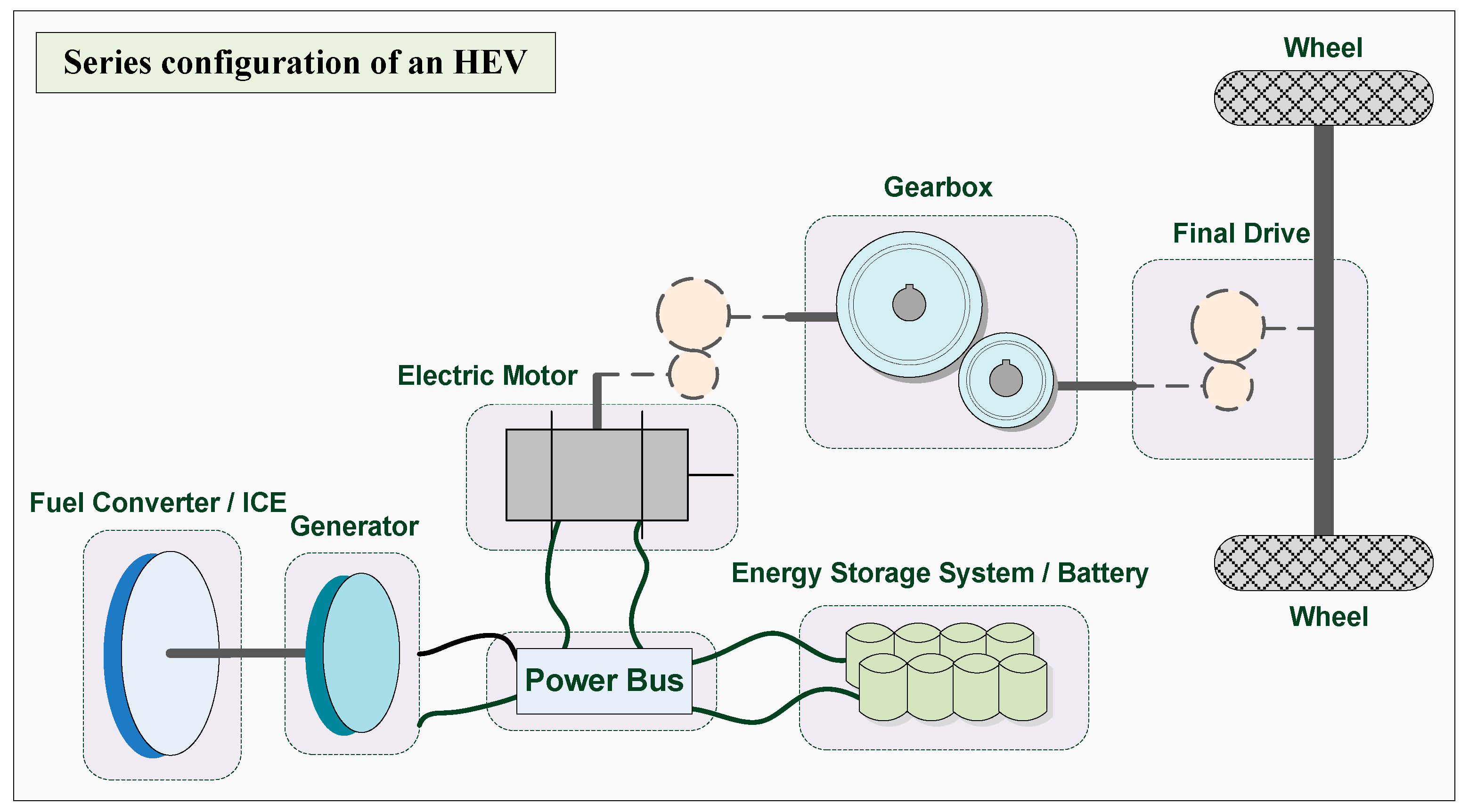
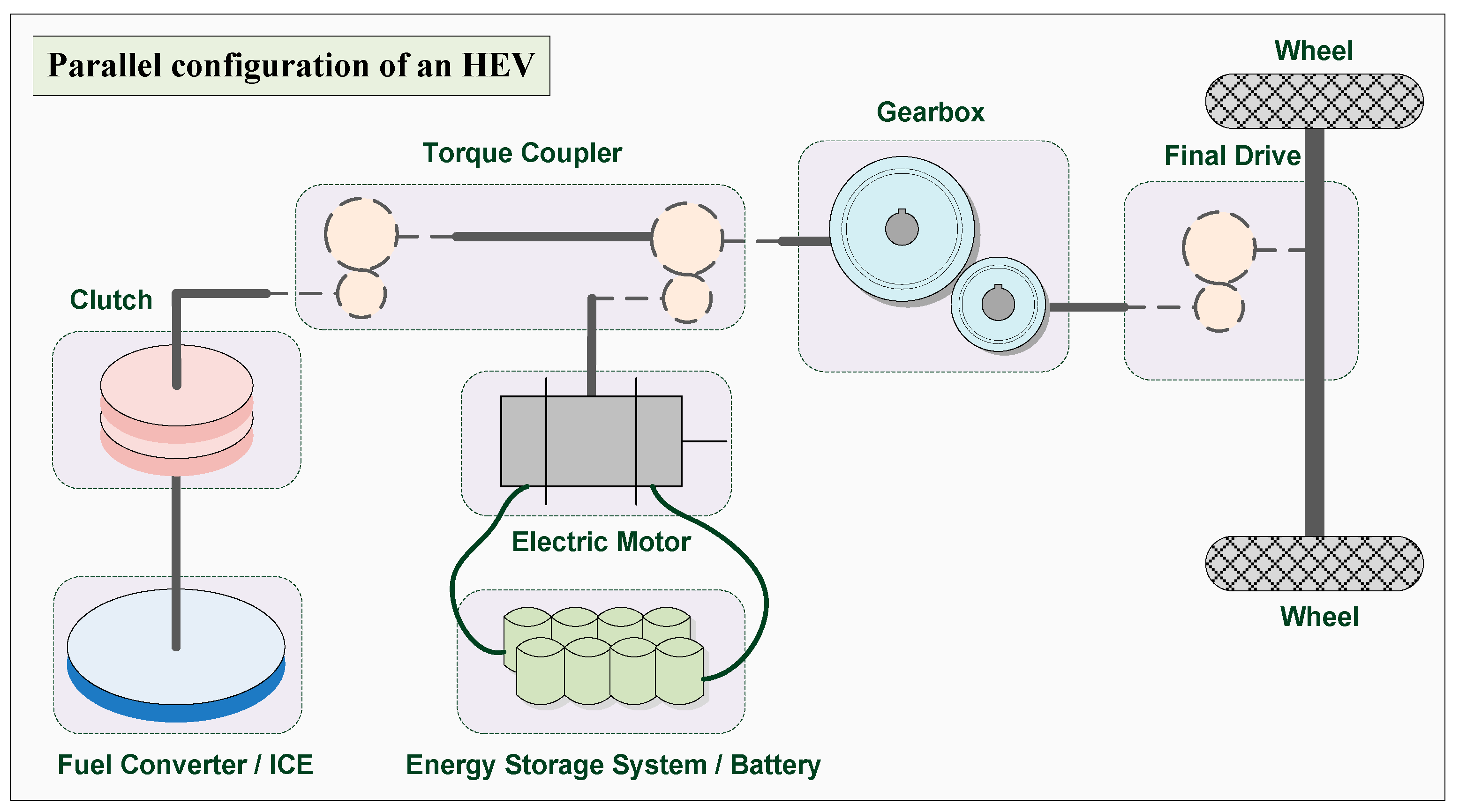
An HEV includes at least two energy converters, i.e., ICE and an electric motor (EM), to generate the mechanical energy required to drive the vehicle and operate the on-board accessories. Therefore, energy flow management plays an important role in HEV efficiency. In order to make HEVs as efficient as possible, the HEV control strategy [
3,
4,
5,
6,
7,
8,
9,
10,
11] is used to properly manage their energy components. By designing an appropriate control strategy, the HEV not only cuts down toxic exhaust emissions, but also maintains the performance of the road-driven vehicle while minimizing fuel consumption. A parameter-optimized control strategy can be used for solve this problem.
In early studies, rule-based control was widely used for parametric optimization. Dynamic programming (DP) can be used to decide the global optimal control parameters [
12] when the driving cycle and vehicle performance are known. Pontryagin’s minimum principle (PMP) may be used to determine the local optimal control parameters, and it can obtain an optimal trajectory in less computing time than DP [
13]. Many HEVs have been discussed in literature, Assanis et al. attempted to improve the fuel consumption (FC) while maintaining the driving performance within the standard limits and using the determined optimal sizes of the ICE, EM and battery pack [
14]. Sciarretta et al. proposed equivalent consumption minimization strategy (ECMS) a strategy based on the definition of the fuel equivalent of the electrical energy for the real-time load control of parallel HEVs [
15]. Johri and Filipi [
16] developed a supervisory controller for HEVs based on the principles of reinforcement learning and neuro-dynamic programming to overcome the curse of dimensionality, and solving policy optimization for a system with very large design state space. Poursamad and Montazeri [
17] presented a fuzzy logic controller that is tuned by a genetic algorithm for parallel HEVs to minimize fuel consumption and emissions. Panday and Bansal developed a fuel efficient energy management strategy which for power-split hybrid electric vehicle using modified state of charge estimation method. Their energy management strategy adapts GA to compute the optimal values of various governing parameters, and then uses Pontryagin’s minimum principle to decide the threshold power at which engine is turned on [
18]. Several targets are usually considered simultaneously in HEV control strategy. To minimize vehicle fuel consumption and engine emissions, and maintain driving performance is the primary purpose of an HEV control strategy. Control strategies designed based on engineering intuition usually fail to achieve satisfactory overall system efficiency owing to the complex nature of HEVs. Several studies based on evolutionary computation have been proposed to determine the optimal parameters for the control strategy for HEVs. Montazeri and Poursamad [
19] proposed a genetic algorithm (GA) to minimize the weighted sum of FC and emissions, and they also considered the Partnership for a New Generation of Vehicles (PNGV) performance requirements as constraints [
20]. Wu et al. [
21] employed a particle swarm optimization (PSO) method to determine the optimal parameters of the powertrain and the control strategy to reduce the FC, emissions, and manufacturing costs of HEVs. Long and Nhan [
22] used bees algorithm (BA) to minimize the weighted sum of FC and emissions, and considered the PNGV constraints for the vehicle performance. Hao et al. [
23] employed the DIvided RECTangle (DIRECT) algorithm to optimize the extracted seven key parameters based on the optimization model of the key parameters from the perspective of fuel economy. More other control algorithms for HEVs can be referred to [
24,
25].
The characteristics of the powertrain system are highly non-linear and discontinuous, and may contain several local optima. However, many methods proposed in the literature lack local search capabilities that makes the optimal solution is difficult to obtain. In this study, a robust evolutionary computation method—memetic algorithm (MA) [
26] is proposed to optimize the control parameters. The “local search” mechanism implemented in the MA greatly enhances its search capabilities. Therefore, it is particularly suitable for solving such problems. MAs were inspired by Dawkins’ notion of a meme [
27]. They are similar, yet superior to the GA. MAs progress through a local search before becoming involved in the evolution process [
28] to ensure that all chromosomes and offspring gain some experiences. To solve this problem, a single objective problem is used and a goal-attainment method is substituted for the original multi-objective optimization problem. The goal of optimization in this problem is to minimize the engine fuel consumption and emissions within the given criteria. In addition, vehicle performance requirements must also be maintained. The used fitness function is proposed according to an electric assist control strategy (EACS) [
4]. The proposed method is then performed for four different driving cycles, including new European driving cycle (NEDC), Federal Test Procedure (FTP), Economic Commission for Europe + Extra-Urban driving cycle (ECE + EUDC) and urban dynamometer driving schedule (UDDS).
Using MAs to solve the control strategy optimization problem associated with minimizing engine fuel consumption and emissions while maintaining driving performance saves a considerable amount of time and provides a global optimal solution. The MA proposed for the control strategy optimization correctly and quickly identifies the optimal parameters required for parallel HEVs. Our experimental results further indicate that MAs applied in the design of control strategy are effective in minimizing minimize fuel consumption and emissions while maintaining driving performance.
3. Control Strategy for Parallel HEV
There are two power-drive units (i.e., fuel converter and electric motor) integrated into the parallel type; therefore, the purpose of the control strategy of the parallel HEV is to decide how to allocate the required torque between the fuel converter and the electric motor during driving. When positive torque is requested, the summation of torques for the fuel converter and electric motor is equal to the demand of the driver. On the contrary, when negative torque is requested, the summation of torques for the electric motor and brake is equal to the demand of the driver while the engine torque is zero.
Several control strategies have been employed for parallel HEVs. EACS [
4] is the most commonly used control strategy; the fuel converter is the major energy provider, and the electric motor is the assistant component for fuel converter. The baseline control strategy (BCS) is used by the ADvanced VehIcle SimulatOR (ADVISOR) in a parallel HEV. Eight independent input parameters are defined to minimize the engine energy usage, and the variables are also usually defined for an EACS [
19], as listed in
Table 1. This EACS is a common method of hybrid control; examples of its application are the Toyota Prius [
31] and Honda Insight [
32].
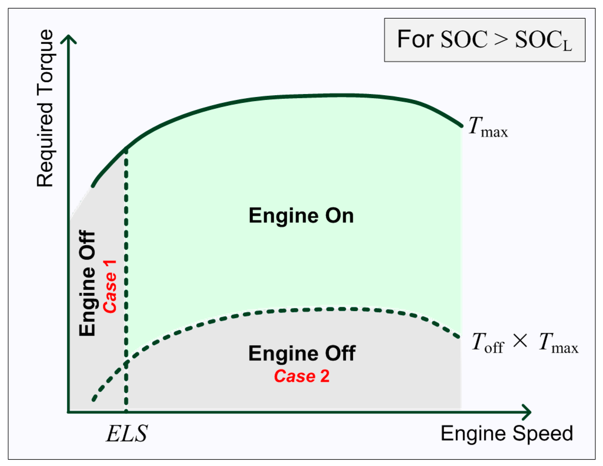
The electric motor is used by the EACS in several specific ways:
- (1)
When the battery state of charge (SOC) is more than
SOCL, the engine will be shut down if the required speed is less than the
ELS, which is also called the electric launch speed (as shown in
Figure 3,
Case 1).
- (2)
When the required torque is less than a minimum torque threshold (
Toff ×
Tmax), the engine will also be shut down (as shown in
Figure 3,
Case 2).
- (3)
The electric motor will provide the total required torque when the engine is shut down (as shown in
Figure 3,
Cases 1 and 2, and
Figure 4,
Case 1).
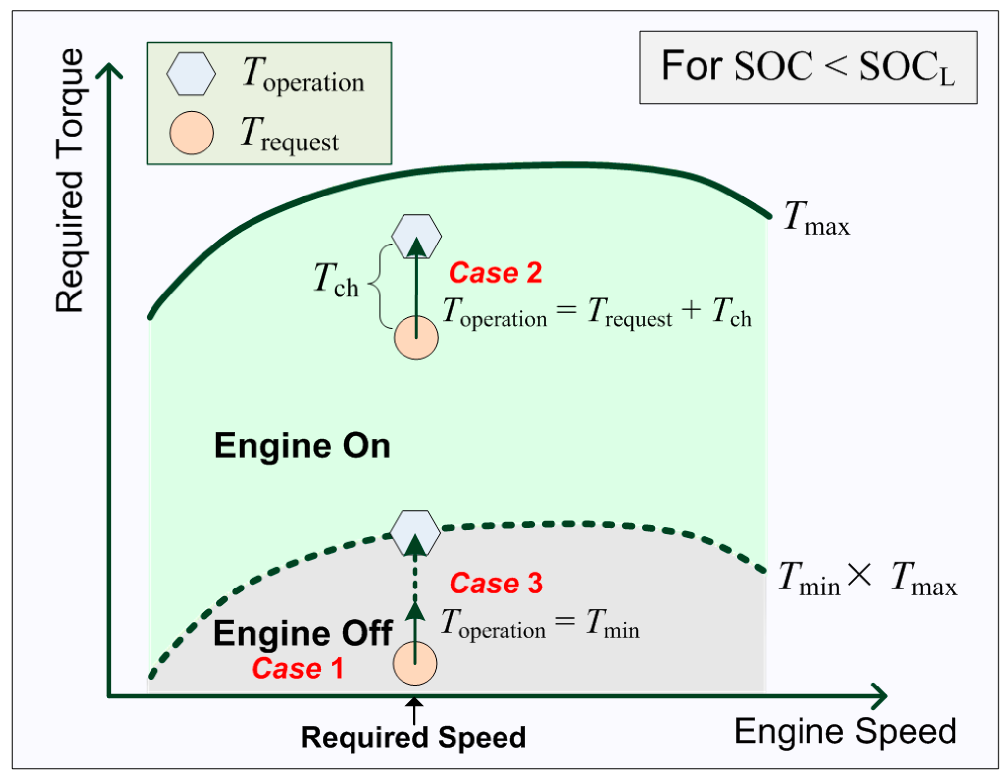
- (4)
When the battery SOC is less than its
SOCL, an alternator-like torque (
Tch) is provided from the engine to charge the battery (as shown in
Figure 4,
Case 2). This alternator-like charging torque is proportional to the difference between the SOC and the average of the
SOCL and
SOCH.
- (5)
The engine charging torque is only applied when the engine is started up (as shown in
Figure 4,
Case 2).
- (6)
To avoid the engine working at an inefficient low torque status, the engine torque must be maintained at the minimum torque threshold (
Tmin ×
Tmax) (as shown in
Figure 4,
Case 3).
The fuel consumption, emissions, battery charge, and vehicle performance are greatly influenced by the control strategy parameters. Consequently, we proposed the robust evolutionary computation method MA to optimize the control parameters in this study.
4. Definition of Objective Function
In the optimization of the control strategy parameters, there are two different approaches to be considered [
33,
34], and they have already been applied to all types of evolutionary computation-based methods related to this problem [
19,
21,
22]. The two different approaches are to optimize a single objective function that is a weighted aggregation of some of the goals and to define the other goals as constraints. Several simultaneous goals including the FC, emissions, charge requirement, and driving performance are managed in the HEV control strategy. In the other words, the HEV control strategy must minimize the weighted sum of the FC and emissions (HC, CO and NO
x) while meeting the charge sustaining requirement and driving performance. We thus define FC, HC, CO, and NO
x as a single objective function that is a weighted aggregation as shown in Equation (1):
where
x is a vector that consists of eight parameters of the control strategy as shown in above-mentioned
Table 1. Chromosome encoding in
Section 5. The design of MA for optimize control strategy of parallel HEVs in details);
wfc,
whc,
wco, and
wnox are defined as weighting factors employed to respectively investigate the influences of the different objectives of FC, HC, CO, and NO
x on the optimization results.
Furthermore, we use the PNGV [
20] as the dynamic performance requirements to guarantee that the vehicle performance is still maintained during optimization.
Table 2 describes the seven PNGV dynamic performance constraints considered.
In order to apply the MA directly to the constrained optimization problem, the seven PNGV constraints are integrated into the objective function [
35] as shown in Equation (2):
where
x is a vector of the parameters of the control strategy as mentioned above and it is a solution within the solution space
S;
is the objective function; and
is the PNGV dynamic performance constraints.
5. The Design of MA for Optimized Control Strategy of Parallel HEVs
MAs were inspired by Dawkins’ conception [
27,
36]. The adjective ‘memetic’ is derived from the term ‘meme’, which denotes an analogue to a gene in the context of cultural evolution [
26]. Similar to GAs, the evolutionary computations involved, such as selection, crossover and mutation are effective in implementing optimal solutions for the control strategy of parallel HEVs. However, in contrast to GAs, MAs progress through a local refinement of individuals before becoming involved in the evolution process and thus assure that all individuals and offspring gain some experiences. After each run, individuals in an MA share information with each other, and superior solutions based on a fitness rule are refined from generation to generation [
37].
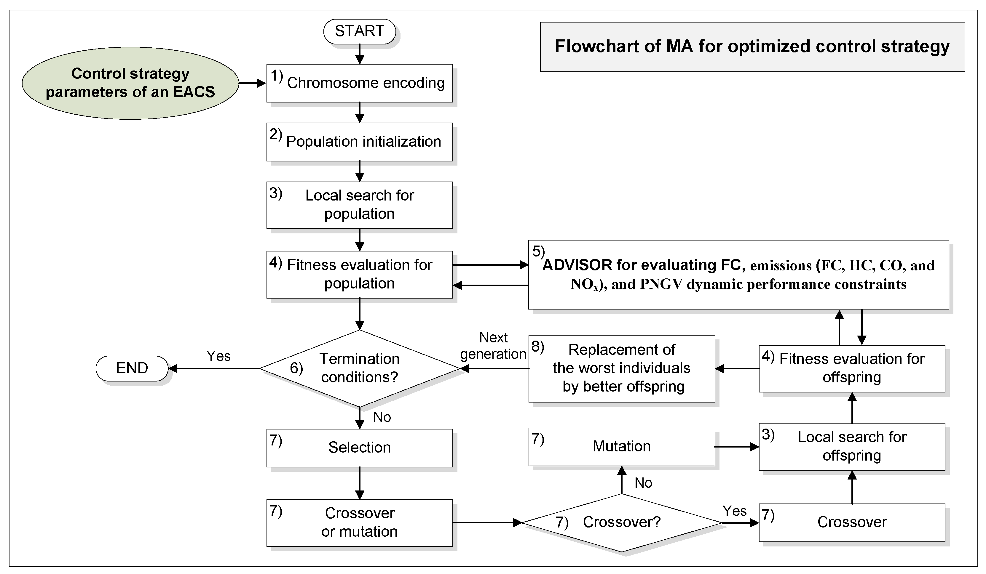
The flowchart of the proposed MA for the optimize control strategy is shown in
Figure 5. There are eight dissociated procedures included: (1) chromosome encoding; (2) population initialization; (3) local search; (4) fitness evaluation; (5) ADVISOR evaluation; (6) judgment on termination conditions; (7) selection, crossover, and mutation processes; and (8) replacement process. These eight procedures are described below.
(1) Chromosome encoding
In order to use the MA to optimize the control strategy parameters in parallel HEVs, a chromosome encoding
x must first be defined. In this study, we use eight independent control strategy parameters of an EACS as shown in
Table 1 as the chromosome encoding for this optimization problem. The chromosome encoding
x is a vector with eight dimensions as shown in Equation (3):
where
x represents a vector that encodes eight parameters of the control strategy.
(2) Population initialization
When performing the MA algorithm for the control strategy optimization, at the start, dozens of chromosomes
are randomly generated for an initial population without duplicates. The values of
,
,
,
,
,
,
and
are randomly generated between default bounds given by the EACS constraint. Their default bounds are presented in
Table 3.
(3) Local search
The local search is the highly capable of identifying superior individuals (i.e., chromosomes with good fitness) from amongst the neighbors of an original individual. The experience of the original individual will be improved by getting experience from the neighbors, and thus a local optimum solution can be acquired. At the beginning of the algorithm, the local search process is performed by all individuals in order to acquire the local optimality of each individual. Furthermore, the local search process is also performed by new generated individuals in each iteration in order for the local optimum to always be retained. Finally, a global optimum is determined. We applied the pseudo-code of the local search to the proposed method which is as follows.
| Local Search Pseudo-Code for the Proposed Method |
| 1 Begin; |
| 2 Select an incremental value d = a × Rand (); |
| 3 For a given individual i∈Population: calculate fitness (i); |
| 4 For j = 1 to the number of variables in individual i; |
| 5 value (j) = value (j) + d; |
| 6 calculate fitness (i); |
| 7 If fitness of the individual is not improved then |
| 8 value (j) = value (j) − d; |
| 9 else if fitness of the individual is improved then |
| 10 retain value (j); |
| 11 Next j; |
| 12 End; |
(4) Fitness evaluation
The fitness function is a function used to evaluate the fitness of the chromosomes in the individuals. To make use of the MA in the simultaneous optimization of parallel HEVs in the study, the fitness function adapts the inverse of the objective function
in Equation (1) and the seven PNGV dynamic performance constraints are considered as penalty functions to maximize the fitness value as shown in Equation (4):
where
are penalty factor selected by trial and error [
22] as indicated in
Table 2, and
are penalty functions that are related to the
i-th constraint
in
Table 2.
The seven penalty functions
for the PNGV dynamic performance constraints are respectively shown in the following Equations (5)–(11).
(5) ADVISOR evaluation
ADVISOR is an abbreviation of “ADvanced VehIcle SimulatOR” which is written in the MATLAB/Simulink environment and was developed by the National Renewable Energy Laboratory in November 1994. It provides the vehicle engineering community with an easy-to-use, flexible, yet robust and supported analysis package for advanced vehicle modeling [
38]. In order to effectively measure the FC, emissions (HC, CO, and NO
x), and driving performance for the used control strategy in parallel HEVs, we have combined the ADVISOR with the proposed MA to evaluate the fitness in chromosomes. When the fitness function is called, the control strategy variables will be passed on to the ADVISOR to calculate the FC, emissions (HC, CO, and NO
x), and driving performance and return their values. These values will then be used to evaluate the fitness of the control strategy.
(6) Judgment on termination conditions
The termination conditions provide the evolutionary computation method to stop meaningless and endless computations. Here, two termination conditions are employed in the proposed method. One is that the maximum number of iterations is reached, and the other is that the fitness value is no longer updated in several following iterations (i.e., the computation has converged).
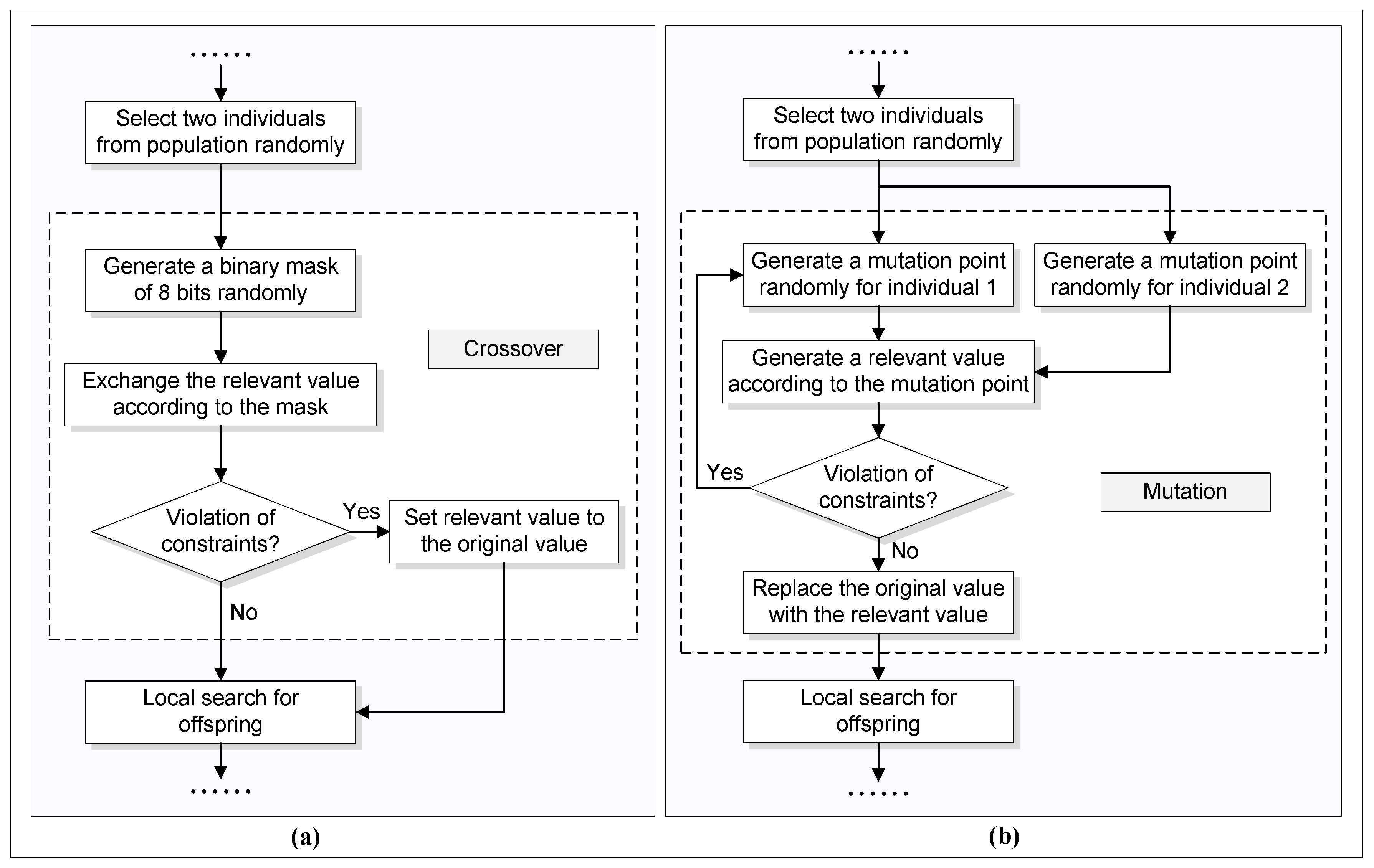
(7) Selection, crossover, and mutation processes
The election, crossover, and mutation processes are the fundamental operations for the evolutionary computation of an MA. The proposed MA only performs either the crossover or mutation process. In the selection process, two individuals are randomly selected from the population for the following crossover or mutation operations. In the crossover process, uniform crossover is applied to the proposed MA. When the crossover probability is satisfied, the selected two individuals will be processed by the crossover operation.
Figure 6a illustrates the flowchart of the crossover process. In the mutation process, one-point mutation is implemented in the proposed MA. When the mutation probability is satisfied, the selected two individuals will be processed by the mutation operation.
Figure 6b illustrates the flowchart of the mutation process.
(8) Replacement process
In order to update the individuals of the population from iteration to iteration, the replacement process is an essential and crucial operation. In the proposed MA, the worst individuals in the population will be replaced with the new individuals. This process is repeated in each next generation until one of the termination conditions is met.
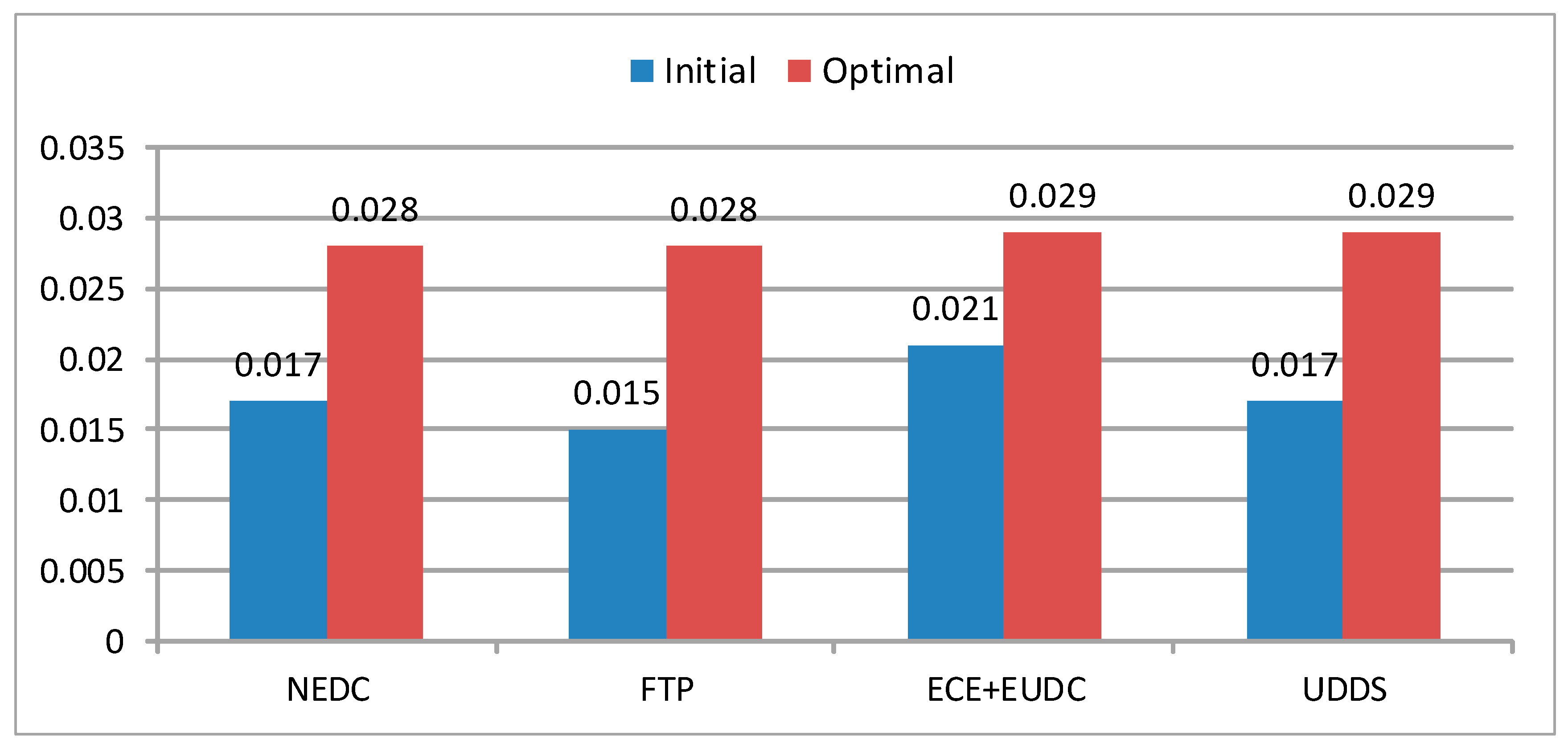
8. Conclusions
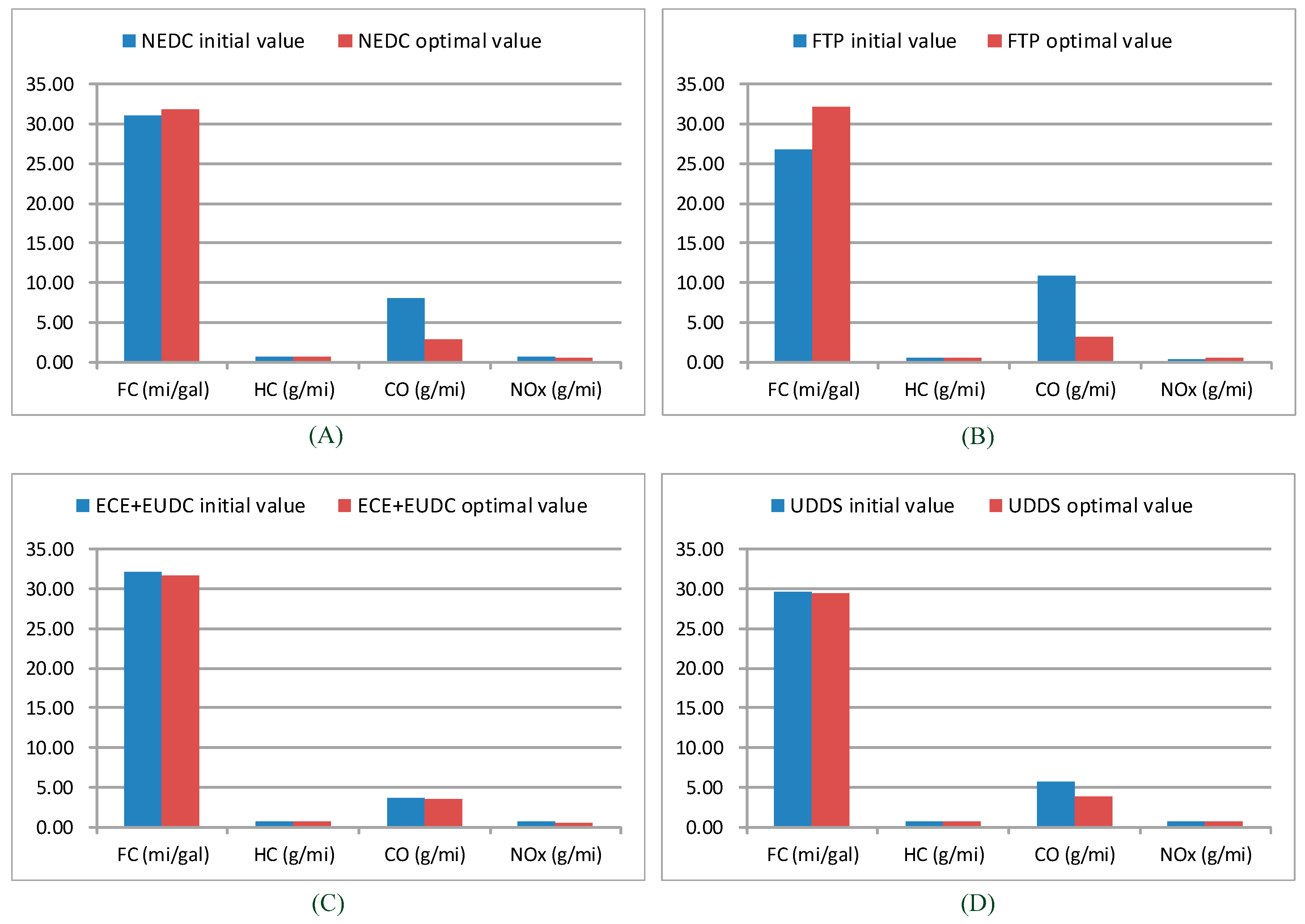
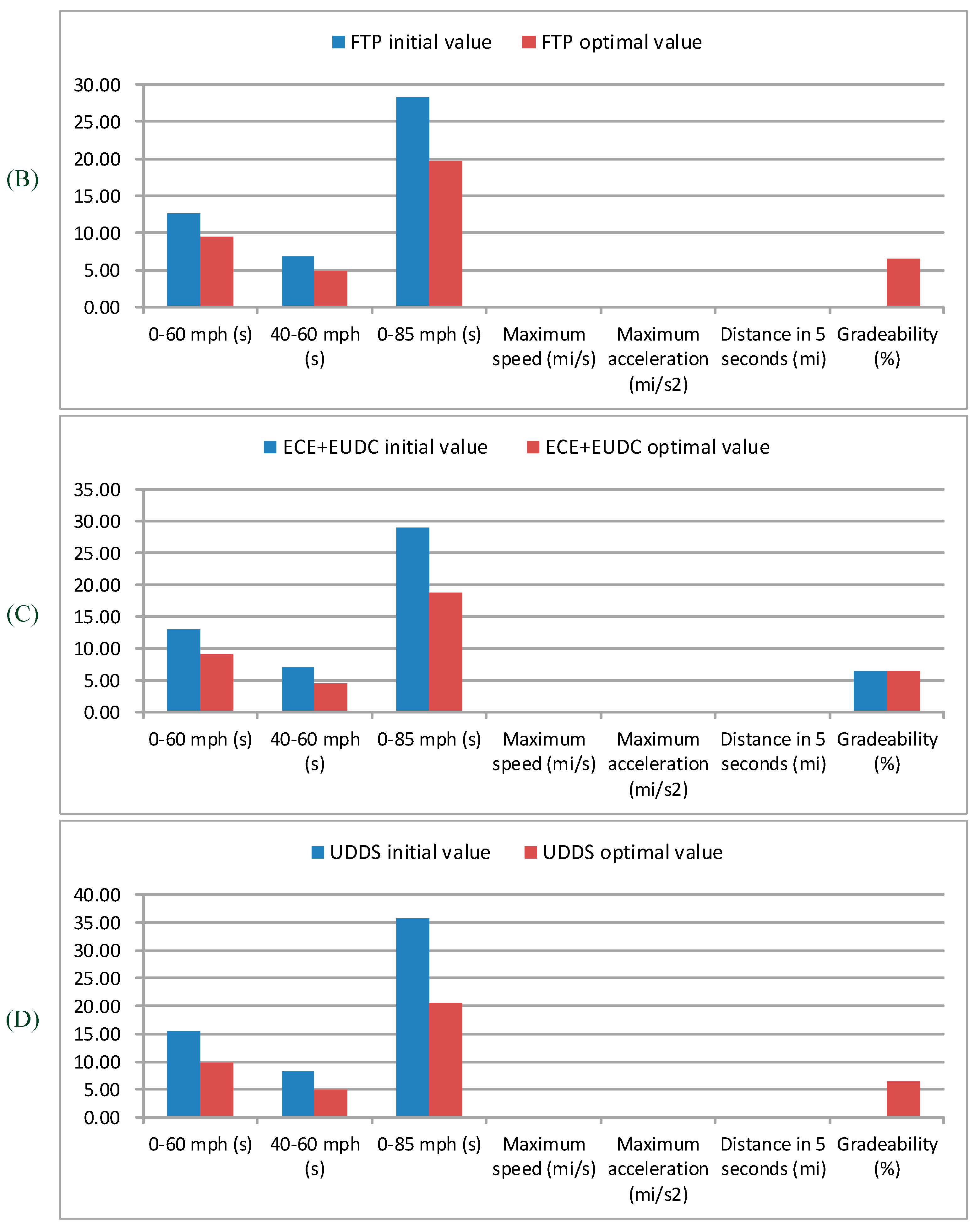
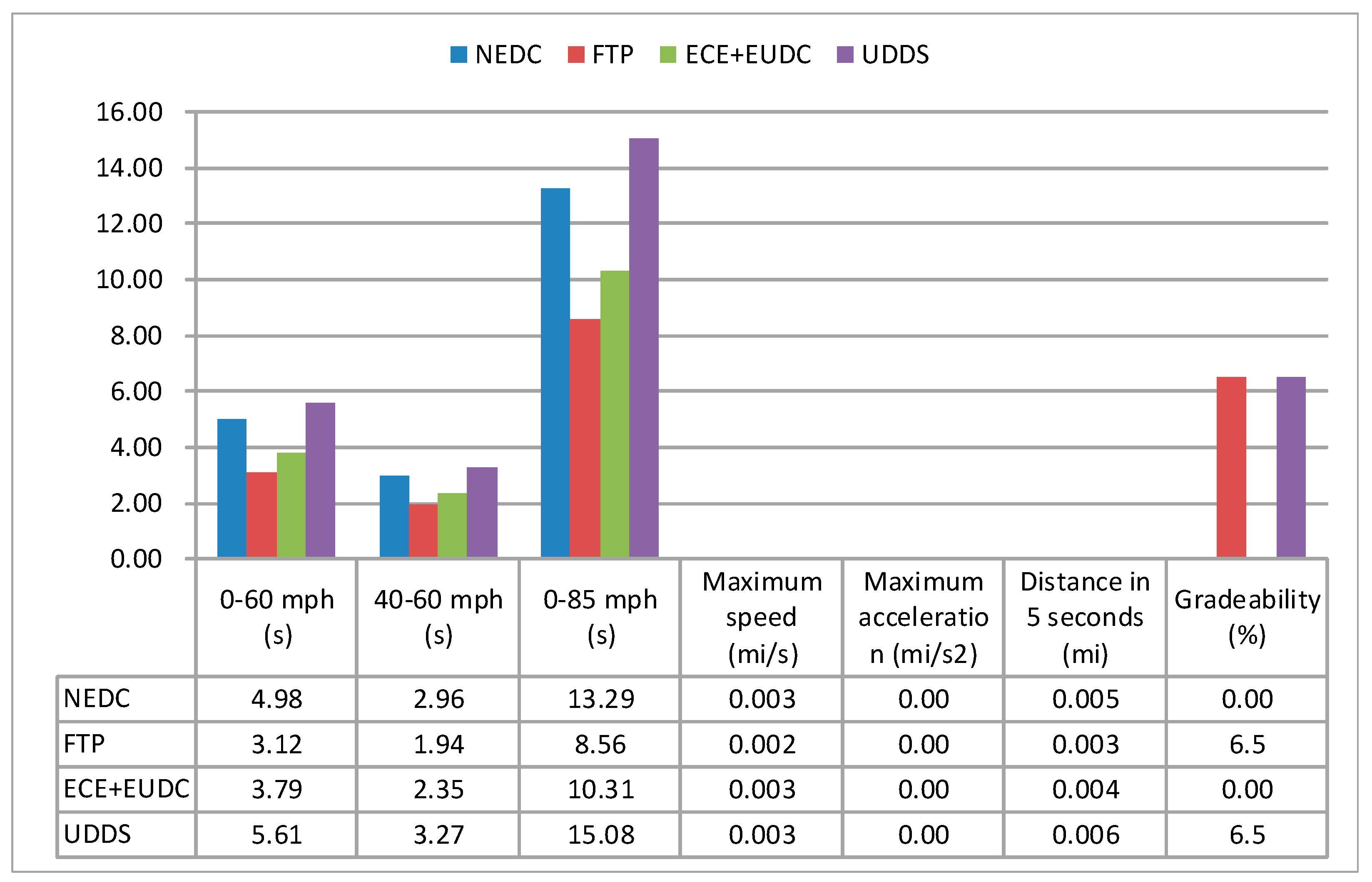
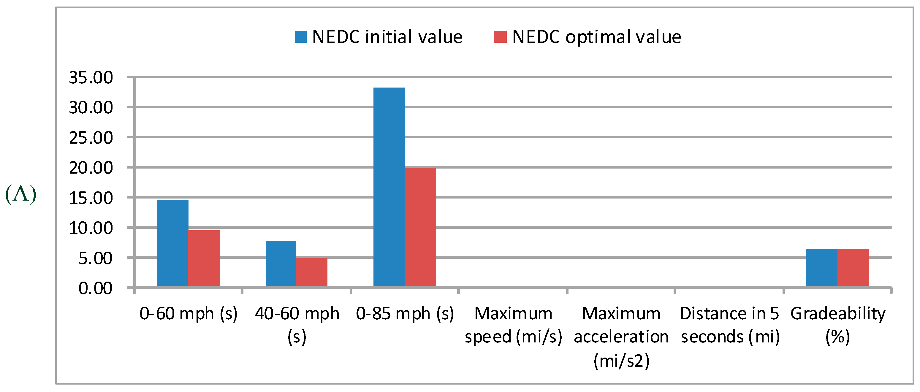
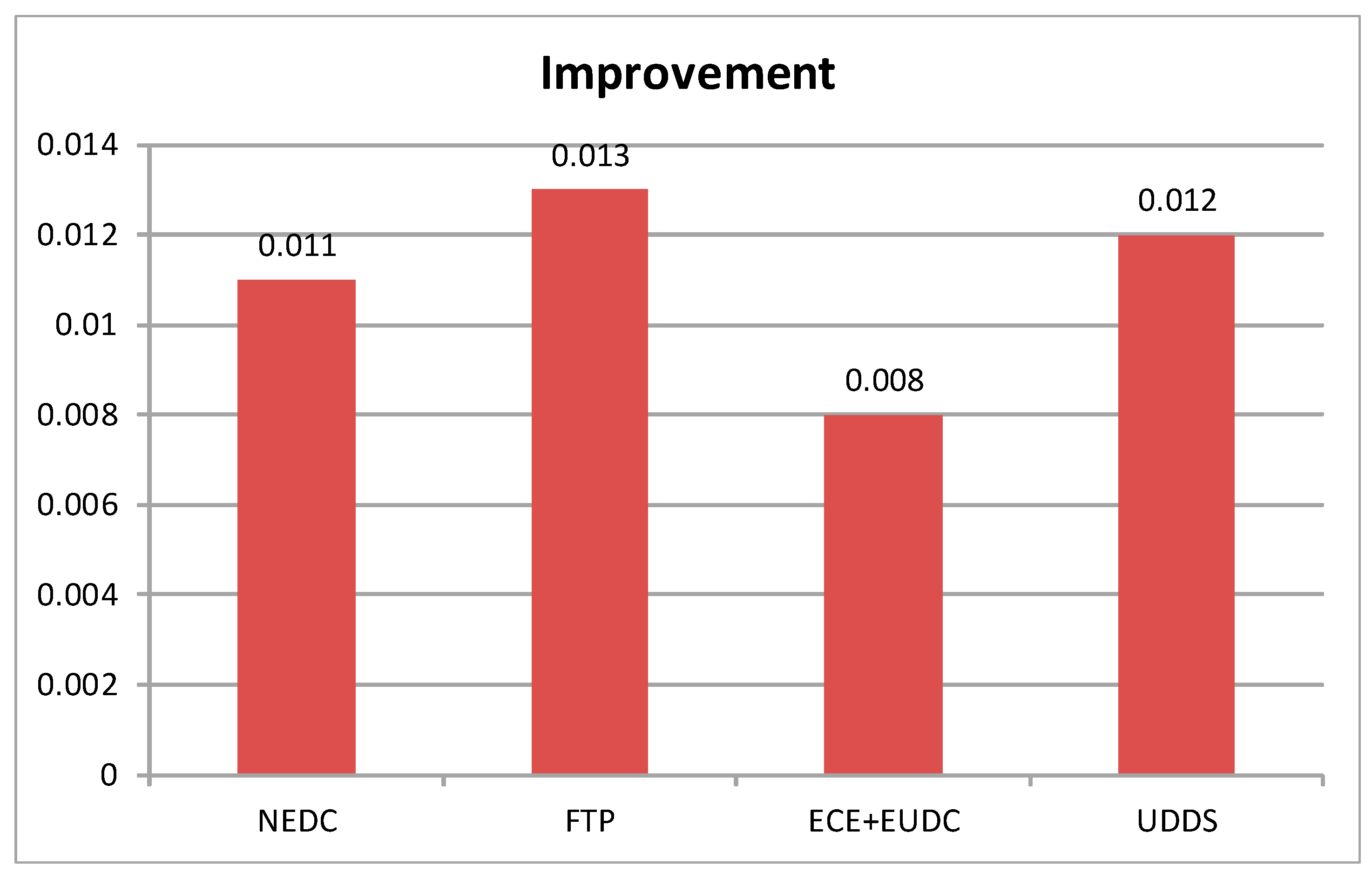
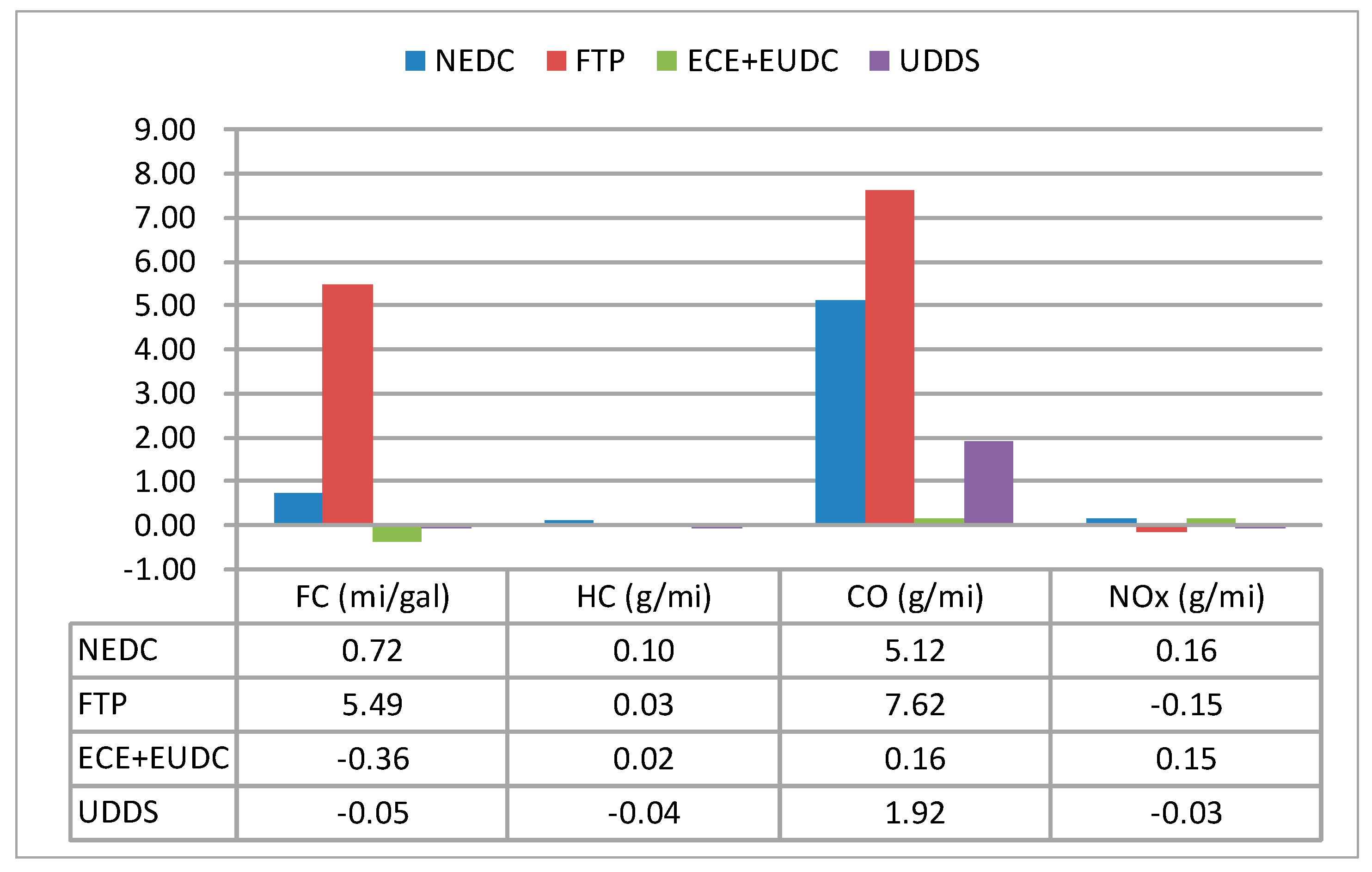
This study proposes a robust evolutionary computation method called a “memetic algorithm (MA)” to optimize the control parameters in parallel HEVs. Its “local search” mechanism greatly enhances the search capabilities for obtaining optimal values of the parameters of the control strategy. We combine the ADVISOR with the fitness function in the proposed MA method and use it to effectively evaluate the FC and emissions (HC, CO, and NOx) of the vehicle engine based on the EACS. Furthermore, we consider that the driving performance requirements, which are referred to as the PNGV constraints, must be satisfied simultaneously. In order to verify the proposed method, we have employed four different driving cycles—NEDC, FTP, ECE + EUDC, and UDDS; the results for these driving cycles are verified. The fitness values of the optimal results are 0.011, 0.013, 0.008, and 0.012, which are better than those of the initial conditions in the driving cycles of the NEDC, FTP, ECE + EUDC, and UDDS, respectively. For the FC and emissions (HC, CO, and NOx), the FC is improved by 0.72 and 5.49 mi/gal for the NEDC and FTP, respectively. The HC emission is reduced by 0.10, 0.03, and 0.02 g/mi for the NEDC, FTP, and ECE + EUDC, respectively. The CO emission is substantially reduced by 5.12, 7.62, 0.16, and 1.92 g/mi for the NEDC, FTP, ECE + EUDC, and UDDS, respectively. The NOx emission is a reduced by 0.16 and 0.15 g/mi for the NEDC and ECE + EUDC, respectively. With regard to the dynamic performance, all the optimal values of the control strategy satisfy the seven PNGV dynamic performance constraints. The acceleration time is reduced by 4.98, 2.96, and 13.29 s for 0–60 mph, 40–60 mph, and 0–85 mph, respectively; the maximum speed is increased by 0.003 mi/s; and the distance traveled in 5 s is increased by 0.005 mi for the NEDC. The acceleration time is respectively reduced in 3.12, 1.94, and 8.56 s for 0–60 mph, 40–60 mph, and 0–85 mph; the maximum speed is increased in 0.002 mi/s; the distance traveled in 5 s is increased in 0.003 mi for the FTP. The acceleration time is reduced by 3.79, 2.35, and 10.31 s for 0–60 mph, 40–60 mph, and 0–85 mph, respectively; the maximum speed is increased by 0.003 mi/s; and the distance traveled in 5 s is increased by 0.004 mi for the ECE + EUDC. The acceleration time is reduced by 5.61, 3.27, and 15.08 s for 0–60 mph, 40–60 mph, and 0–85 mph, respectively; the maximum speed is increased by 0.003 mi/s; and the distance traveled in 5 s is increased by 0.006 mi for the UDDS. Furthermore, the maximum acceleration is maintained at 0.003 mi/s2 and the gradeability reached a value of 6.5% in all the considered driving cycles. The results indicate that the proposed MA method is capable of determining the optimal parameters of the control strategy for parallel HEVs. It helps to improve the fuel consumption and reduce the emissions, as well as guarantee vehicle performance.


