1. Introduction
The miniaturization of consumer electronics and mechanical structures has been receiving a great deal of attention for a considerable time. Extensive fabrication techniques have been developed for complex structures, including gray-scale lithography, reactive ion etching, LIGA (lithography, electroplating, and molding), and electron beam lithography [
1,
2,
3]. Several three-dimensional (3D) fabrication techniques have been developed recently for the fabrication of conductive structures with electrical functionality, which include micro-stereolithography [
4], micro-laser-sintering [
5], inkjet printing [
6,
7], and continuous writing [
8,
9,
10]. These offer dramatic advantages over typical methods in terms of low cost, large area, and a quick processing time, but still suffer from some limitations with respect to the structure and material.
Laser writing creates patterned structures through ablation or selective sintering. Lee proposed a micro-stereolithography process for the fabrication of metal microstructures that used a low-viscosity metal powder suspension sintered by a focused laser beam [
4]. Regenfuss realized structural features and performed laser micro-sintering with sub-micrometer grained metal powders, where the challenge was the high temperature and porosity [
5]. These techniques often require expensive equipment or costly photopolymers.
Lower-cost inkjet printing for the creation of functional 3D structures of material with specific electrical properties, layer by layer, have also been extensively studied. Fuller additively built electrical circuitry by inkjet printing using nanoparticle metal colloids which were then sintered at 300 °C [
6]. Kullmann used piezoelectric inkjet printing to grow micro-wires and micro-walls, selectively combined with simultaneous in situ laser annealing [
7]. However, the printing performance was limited by the rough edges and the low viscosity of the material.
To achieve a good flat surface in a short time at a low cost, several direct-write processes using micro-nozzles or syringe needles have been developed in one-step processes to make continuous conducting structures. Lebel used direct-write micro-extrusion to fabricate carbon nanotube/polymer nanocomposite coils through a micro-nozzle which were then cured using UV irradiation which followed the extrusion point [
8]. Lu presented a hybrid technology combined with direct-write and projection micro-stereolithography with carbon nanotubes dispersed in a photopolymer solution for 3D conductive structures [
9]. Ladd demonstrated free-standing 3D microstructures patterning by extruding a low-viscosity liquid metal through a capillary [
10].
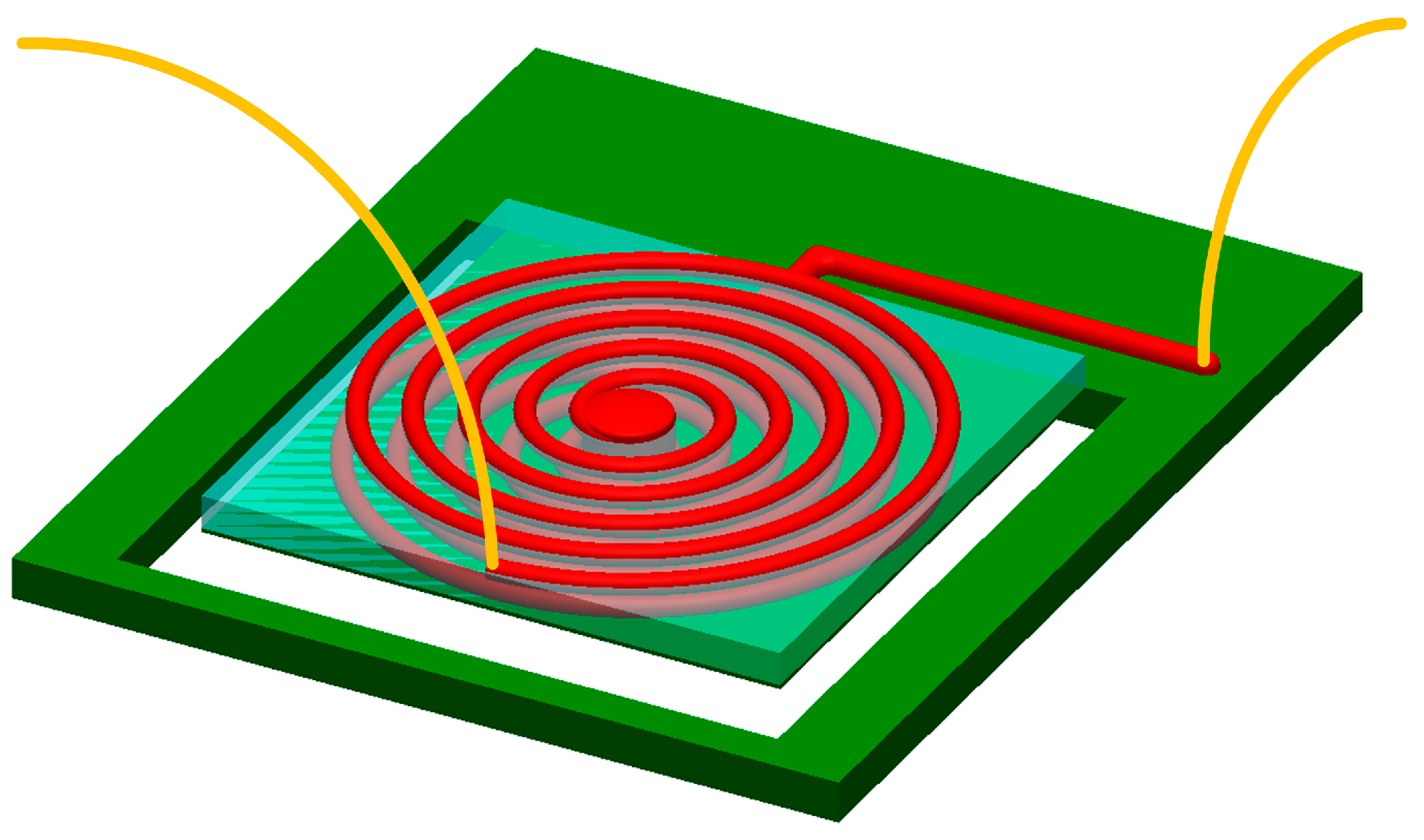
In this study we used a three-axis dispenser to demonstrate conductive-structure fabrication on micro electromagnetic generators [
11,
12]. To increase the output voltage and power, continuous volumes of metallic or insulating material were stacked on a cantilever microstructure at computer-defined positions, which enabled the all-additive fabrication of layers of coils without using vacuum deposition or any high-temperature process. Movement of the coils in the magnetic field from external permanent magnets causes the induction of an electromotive force according to Faraday’s law. The output power would increase as the numbers of coil turns increase. A schematic of the micro-generator with two coils is shown in
Figure 1.
2. Theory
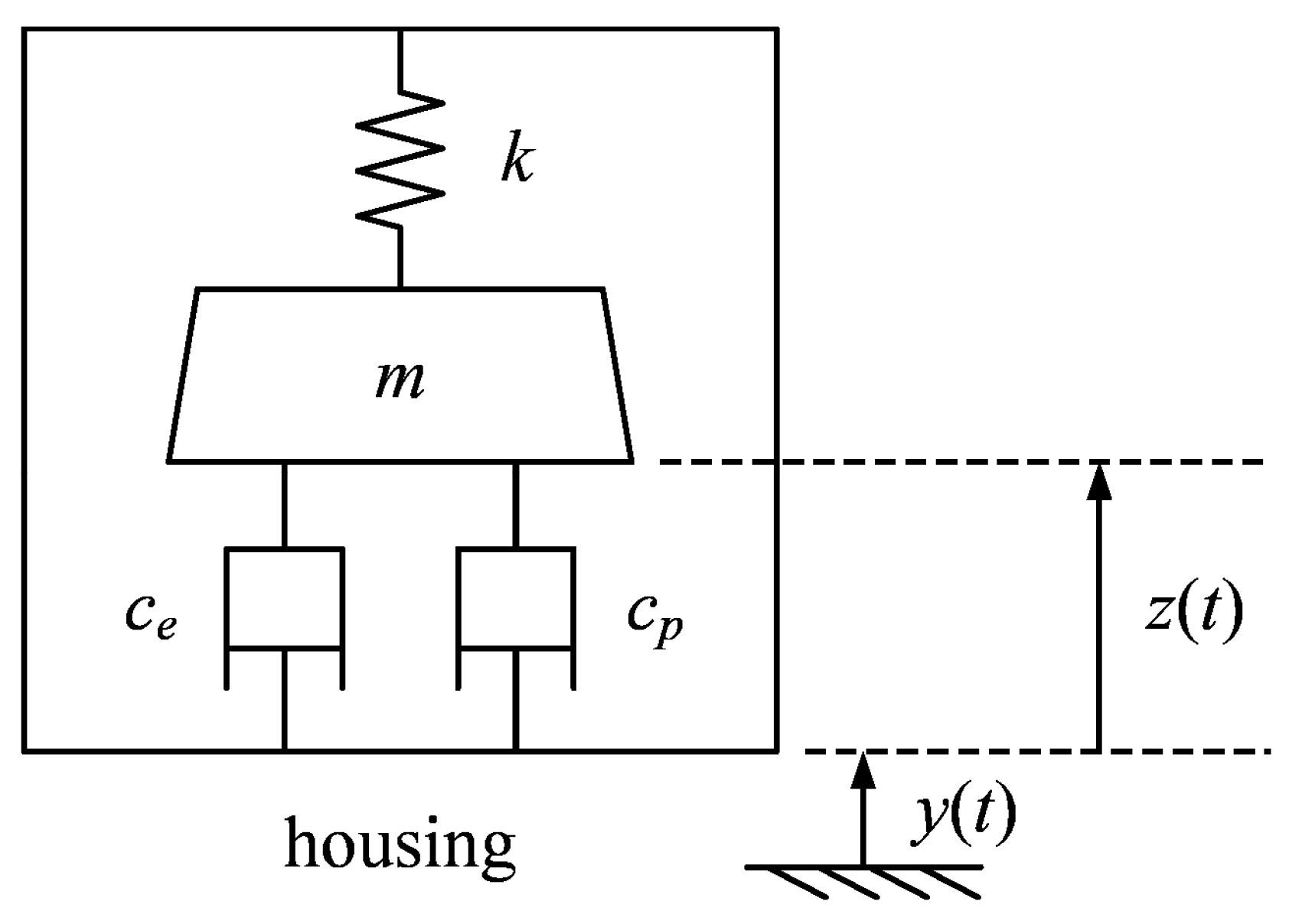
A micro electromagnetic generator can be modeled as a second-order system,
, where
is the relative displacement of the mass to the vibrating housing (see
Figure 2).
For a given sinusoidal displacement input of the housing,
, the time response of the system can be expressed by [
13,
14,
15]
where
is the natural frequency given by
,
is the overall damping ratio given by
, and
is the overall damping coefficient. When the system is operated at the natural frequency,
, the phase (
) equals −90°, and the relative displacement,
, is given by
where
,
,
and
are defined as the transducer damping coefficient, the parasitic damping coefficient, the transducer damping ratio and the parasitic damping ratio, respectively.
The output power is generated by the relative motion between an external magnet and the coils fabricated on the cantilevers. The instantaneous kinetic power dissipation of the mass due to the damping is defined by
. Part of the power is converted to electricity by electromagnetic transduction, and the rest is lost through the parasitic damping of the system. For maximum electrical power generation, the energy harvester is typically designed to operate at a resonance which results in large coil displacement. The average power generation can be further expressed by [
14,
15,
16]
The power generation is therefore a function of the mass, damping ratio, natural frequency, and input displacement.
3. Fabrication
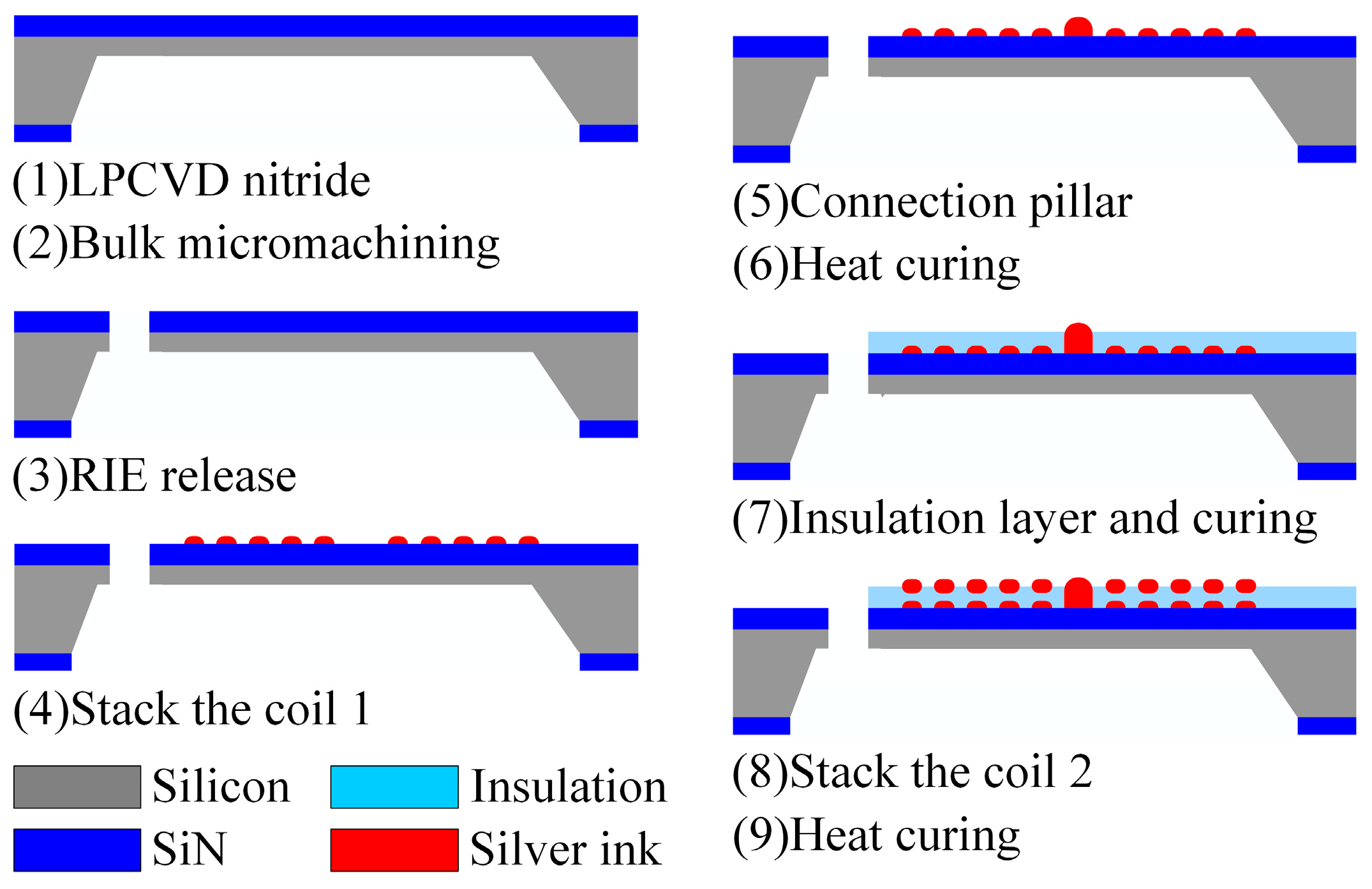
The fabrication processes of the proposed energy harvester are schematically shown in
Figure 3. First, a silicon-based cantilever diaphragm was fabricated using a standard microelectromechanical systems (MEMS) process. To make the coils on the 7 mm × 7 mm cantilevers, conductive ink was extruded from a nozzle over a helical path to form the first coil (one to three layers) which was then cured at 150 °C for 30 min. Insulating material was then extruded evenly over the top of the first coil and cured, and then more conductive ink (one to three layers) was deposited to form the second coil and a final 30 min curing at 150 °C was done. This technique gives better control over the thick metal laid down, by means of pressure, speed, and temperature, than a typical micromachining process does.
Table 1 shows the detailed sizes of the fabricated generator.
Figure 4 shows the arrangement of several layers of metal used to form the coils and the insulation.
Figure 5 shows the cross-sectional photos for a single coil.
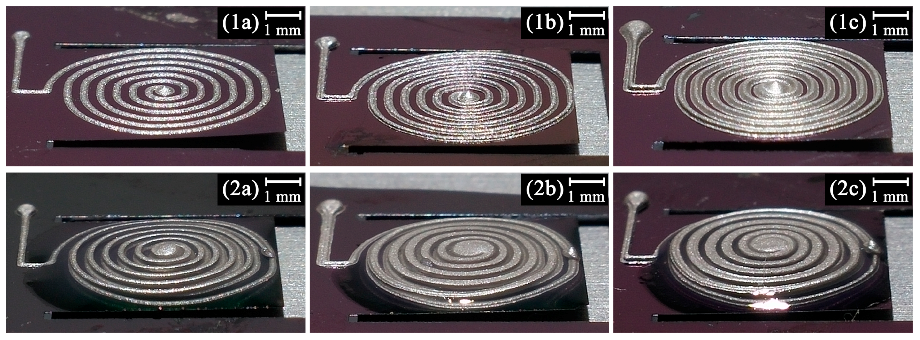
Figure 6 shows photos of six electromagnetic energy harvesters of one or two coils with one to three layers: (1a, 2a) one layer, (1b, 2b) two layers, and (1c, 2c) three layers.
4. Measurement
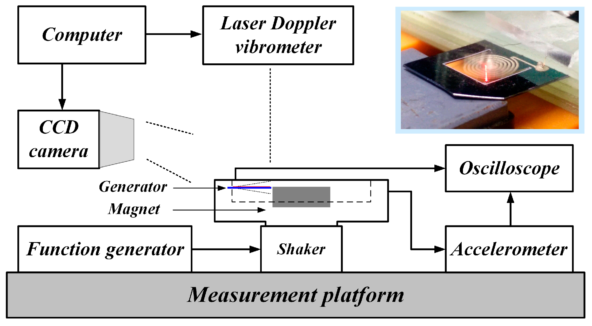
The fabricated micro-generators were tested by using a vibrational system, as shown in the schematic in
Figure 7. A function generator was used to control the vibration frequency between 100 and 600 Hz. An accelerometer was used to measure the acceleration of the generators. An external magnet was placed at a distance of 0.5 mm from the generator.
Measurements which included resistance, voltage, and power were performed on six different prototypes: 1a, 1b, 1c, 2a, 2b, 2c. We measured the resistance of the load, and calculated the power of the generator by using Equation (6) as
where
is the measured voltage, and
is the load resistance.
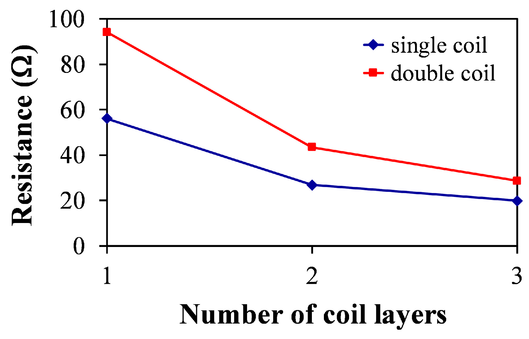
Figure 8 shows the measured resistance for micro-generators with different numbers of coil layers for a single or double coil. The resistance was inversely proportional to the number of layers.
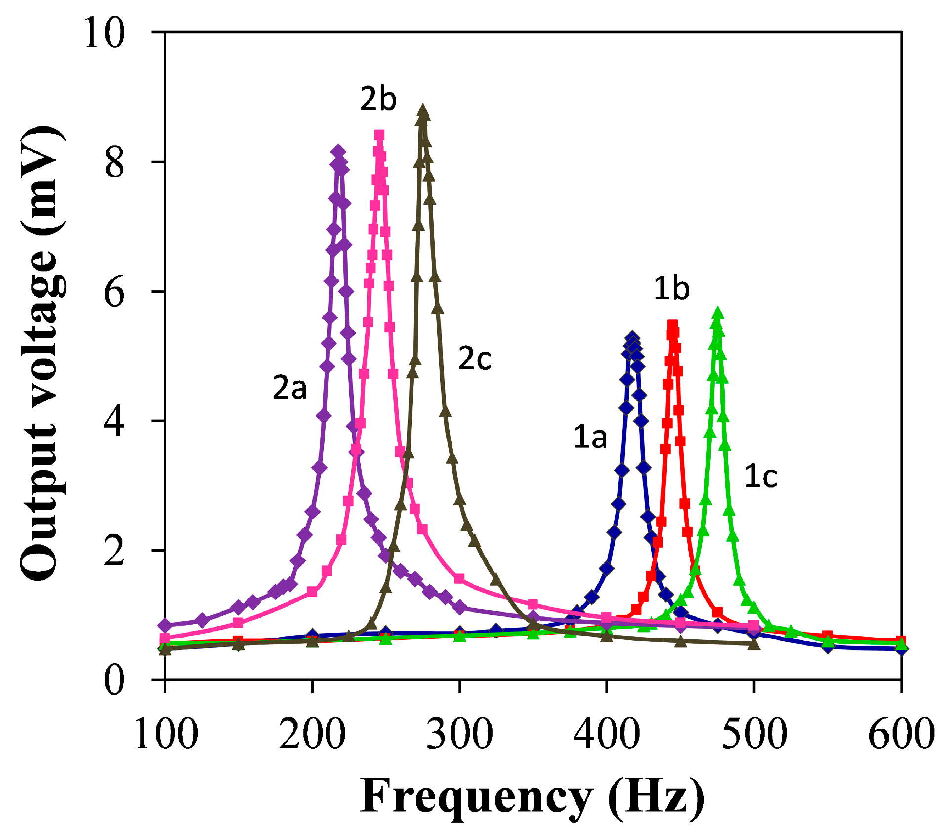
Figure 9 shows the measured open-circuit peak-to-peak voltages under an acceleration of 5 g with respect to the vibration frequencies as viewed on the oscilloscope. The output voltages had maximum values at frequencies of 417, 445, and 475 Hz for a single coil (1a, 1b, 1c) and 218, 246, and 275 Hz for a double coil (2a, 2b, 2c).
For power measurements, the generator was connected to a resistive load and operated at its fundamental frequency.
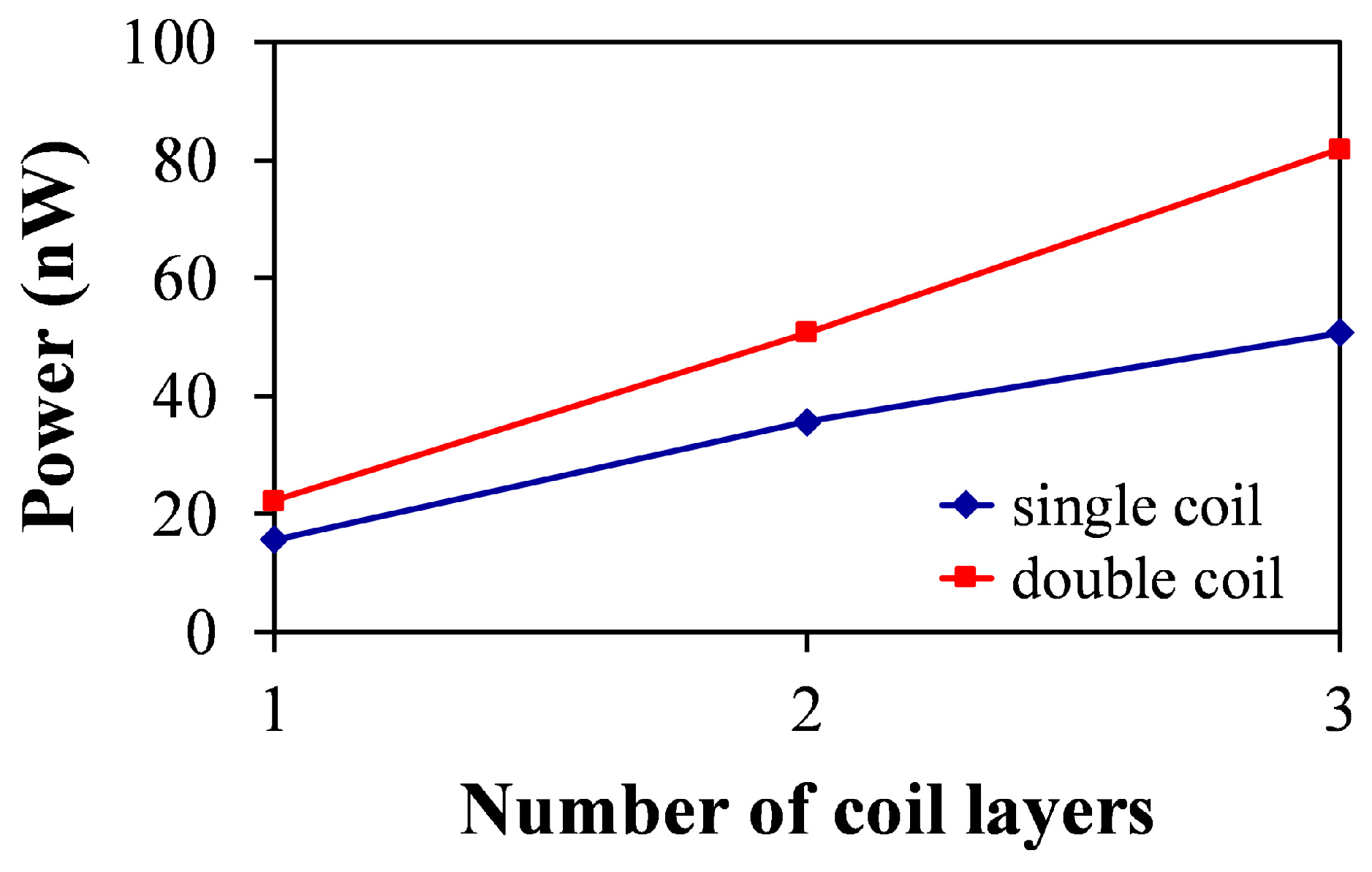
Figure 10 shows the measured output power. For a single coil, the average power produced was 16, 36, and 51 nW. For two coils, the average power produced was 22, 51, and 82 nW. This power increase was due to the greater number of coil turns. When a three-layer coil is compared with a single-layer coil, the resistance decreases and the output power increases by 218% in the case of a single coil, or 272% in the case of a double coil.
5. Discussion
For energy harvesting, the typical vibrational frequencies are lower than 200 Hz, yet some have higher frequencies [
17,
18,
19]. According to
Table 2, the proposed structures with resonant frequencies from 218 to 475 Hz have the potential to be used in motorized equipment, such as transformers, refrigerators, car engines, etc. [
17,
18,
19]. To further reduce the resonant frequency, possible methods are adding proof mass on the cantilever, modifying the coil structure, or making the cantilever thinner.
Conventional semiconductor processes use sputtering, electroplating, laser micromachining, or E-beam evaporating [
20,
21,
22,
23,
24,
25,
26,
27] to make conductive coils. In this work, we used a conductive direct-write method with silver ink to fabricate the conductive structures. This method provides a faster or cheaper alternative to the conventional methods.
Table 3 shows the comparison of different fabrication methods for making the conductive coils of the energy harvesters, and the output power of the proposed method is acceptable.
According to Equation (6), reducing the resistance of the coils or enhancing the induced voltage would increase the generator’s power. In other words, the profile of the coil (turns and width) would have influence on the energy harvester performance. Observed from the experimental results (
Figure 8 and
Figure 9), it can be found that the resistance decreases as the thickness of the coils increases, and the output voltage increases as the number of coils increases. Therefore, by using the proposed direct-write method, the coil resistance and coil loops can be adjusted without too much trouble, thus improving the output performance of the generator.
6. Conclusions
Micro-generators fabricated by using direct-write conductive materials on cantilever diaphragms are proposed. Thick coil structures were fabricated as a whole and then heat-cured, largely suppressing the stress gradient. The generator vibrates around an external magnet and converts the vibrational power into electrical power. The resistance, open circuit voltage, and output power of six prototypes were measured. To increase the output power, the number of coils was increased and the resistance of the coils was reduced by increasing the number of layers of metal used. A single coil can produce 16, 36, and 51 nW at 417, 445, and 475 Hz, and a double coil can produce 22, 51, and 82 nW at 218, 246, and 275 Hz, both in response to 5 g vibration acceleration. This technique shows great promise for use in applications such as the powering of intelligent sensor networks.
Acknowledgments
The authors would like to acknowledge the support by the Ministry of Science and Technology, Taiwan, on grant no. MOST 104-2221-E-008-018-MY2 and MOST 105-2221-E-008-043. The authors would like to thank the National Center for High-Performance Computing, Taiwan, for providing software and facilities.
Author Contributions
Y.-Y.F. and S.-J.C. conceived and designed the experiments; Y.-Y.F. and Y.-L.T. performed the experiments; Y.-Y.F. and S.-J.C. analyzed the data; Y.-Y.F. and S.-J.C. wrote the paper.
Conflicts of Interest
The authors declare no conflict of interest.
References
- Lewis, J.A.; Gratson, G.M. Direct writing in three dimensions. Mater. Today 2004, 7, 32–39. [Google Scholar] [CrossRef]
- Vaezi, M.; Seitz, H.; Yang, S. A review on 3D micro-additive manufacturing technologies. Int. J. Adv. Manuf. Technol. 2013, 67, 1721–1754. [Google Scholar] [CrossRef]
- Farahani, R.D.; Chizari, K.; Therriault, D. Three-dimensional printing of freeform helical microstructures: A review. Nanoscale 2014, 6, 10470–10485. [Google Scholar] [CrossRef] [PubMed]
- Lee, J.W.; Lee, I.H.; Cho, D.W. Development of micro-stereolithography technology using metal powder. Microelectron. Eng. 2006, 83, 1253–1256. [Google Scholar] [CrossRef]
- Regenfuss, P.; Streek, A.; Hartwig, L.; Klötzer, S.; Brabant, Th.; Horn, M.; Ebert, R.; Exner, H. Principles of laser micro sintering. Rapid Prototyp. J. 2007, 13, 204–212. [Google Scholar] [CrossRef]
- Fuller, S.B.; Wilhelm, E.J.; Jacobson, J.M. Ink-jet printed nanoparticle microelectromechanical systems. J. Microelectromech. Syst. 2002, 11, 54–60. [Google Scholar] [CrossRef]
- Kullmann, C.; Schirmer, N.C.; Lee, M.T.; Ko, S.H.; Hotz, N.; Grigoropoulos, C.P.; Poulikakos, D. 3D micro-structures by piezoelectric inkjet printing of gold nanofluids. J. Micromech. Microeng. 2012, 22, 055022. [Google Scholar] [CrossRef]
- Lebel, L.L.; Aissa, B.; Khakani, A.E.; Therriault, D. Ultraviolet-assisted direct-write fabrication of carbon nanotube/polymer nanocomposite microcoils. Adv. Mater. 2010, 22, 592–596. [Google Scholar] [CrossRef] [PubMed]
- Lu, Y.; Vatani, M.; Choi, J.W. Direct-write/cure conductive polymer nanocomposites for 3D structural electronics. JMST 2013, 27, 2929–2934. [Google Scholar] [CrossRef]
- Ladd, C.; So, J.H.; Muth, J.; Dickey, M.D. 3D printing of free standing liquid metal microstructures. Adv. Mater. 2013, 25, 5081–5085. [Google Scholar] [CrossRef] [PubMed]
- Feng, Y.Y.; Chen, S.J.; Hsieh, P.H.; Chu, W.T. Fabrication of an electro-thermal micro-gripper with elliptical cross-sections using silver-nickel composite ink. Sens. Actuators A Phys. 2016, 245, 106–112. [Google Scholar] [CrossRef]
- Chen, S.J.; Feng, Y.Y.; Liu, S.Y. Fabrication of a three dimensional cantilevered vibration energy harvester using silver ink. In Proceedings of the 2015 28th IEEE International Conference on Micro Electro Mechanical Systems (MEMS), Estoril, Portugal, 18–22 January 2015.
- Williams, C.B.; Yates, R.B. Analysis of a micro-electric generator for microsystems. Sens. Actuators A 1996, 52, 8–11. [Google Scholar] [CrossRef]
- El-hami, M.; Glynne-Jones, P.; White, N.M.; Hill, M.; Beeby, S.; James, E.; Brown, A.D.; Ross, J.N. Design and fabrication of a new vibration-based electromechanical power generator. Sens. Actuators A 2001, 92, 335–342. [Google Scholar] [CrossRef]
- Chen, S.J.; Wu, J.Y. Fabrication of a 2-DOF electromagnetic energy harvester with in-phase vibrational bandwidth broadening. Smart Mater. Struct. 2016, 25, 095047. [Google Scholar] [CrossRef]
- Roundy, S.; Leland, E.S.; Baker, J.; Carleton, E.; Reilly, E.; Lai, E.; Otis, B.; Rabaey, J.M.; Wright, P.K.; Sundararajan, V. Improving power output for vibration-based energy scavengers. IEEE Pervasive Comput. 2005, 4, 28–36. [Google Scholar] [CrossRef]
- Roundy, S.; Wright, P.K.; Rabaye, J. A study of low level vibrations as a power source for wireless sensor nodes. Comput. Commun. 2003, 26, 1131–1144. [Google Scholar] [CrossRef]
- Muthalif, A.G.A.; Turahim, K.K.; Rahim, S.A. Active vibration isolation system to improve free space optics communication. In Proceedings of the 2012 International Conference on Information Technology and Software Engineering; Springer: Berlin/Heidelberg, Germany, 2013; pp. 369–378. [Google Scholar]
- Roundy, S. On the effectiveness of vibration-based energy harvesting. J. Intell. Mater. Syst. Struct. 2005, 16, 809–823. [Google Scholar] [CrossRef]
- Zhang, Q.; Wang, Y.; Zhao, L.; Kim, E.S. Integration of microfabricated low resistance and thousand turn coils for vibration energy harvesting. J. Micromech. Mircoeng. 2016, 26, 1–10. [Google Scholar] [CrossRef]
- Tao, K.; Ding, G.; Wang, P.; Yang, Z.; Wang, Y. Fully integrated micro electromagnetic vibration energy harvesters with micro-patterning of bonded magnets. In Proceedings of the 2012 IEEE 25th International Conference on Micro Electro Mechanical Systems (MEMS), Paris, France, 29 January–2 February 2012; pp. 1237–1240.
- Hoffmann, D.; Kallenbach, C.; Dobmaier, M.; Folkmer, B.; Manoli, Y. Flexible polyimide film technology for vibration energy harvesting. In Proceedings of the Power-MEMS 2009, Washington, DC, USA, 1–4 December 2009; pp. 455–458.
- Zhang, Q.; Kim, E.S. Micromachined energy-harvester stack with enhanced electromagnetic induction through vertical integration of magnets. J. Microelectromech. Syst. 2015, 24, 384–394. [Google Scholar] [CrossRef]
- Sari, I.; Balkan, T.; Kulah, H. An electromagnetic micro power generator for low-frequency environmental vibrations based on the frequency upconversion technique. J. Microelectromech. Syst. 2010, 19, 14–27. [Google Scholar] [CrossRef]
- Wang, N.; Arnold, D.P. Fully batch-fabricated MEMS magnetic vibrational energy harvesters. In Proceedings of the Power-MEMS 2009, Washington, DC, USA, 1–4 December 2009; pp. 348–351.
- Ching, N.N.H.; Wong, H.Y.; Li, W.J.; Leong, P.H.W.; Wen, Z. A laser-micromachined multi-modal resonating power transducer for wireless sensing systems. Sens. Actuators A Phys. 2002, 97, 685–690. [Google Scholar] [CrossRef]
- Zhang, Q.; Chen, S.J.; Baumgartel, L.; Lin, A.; Kim, E.S. Microelectromagnetic energy harvester with integrated magnets. In Proceedings of the 2011 16th International Solid-State Sensors, Actuators and Microsystems Conference (TRANSDUCERS), Beijing, China, 5–9 June 2011; pp. 1657–1660.
© 2017 by the authors. Licensee MDPI, Basel, Switzerland. This article is an open access article distributed under the terms and conditions of the Creative Commons Attribution (CC BY) license ( http://creativecommons.org/licenses/by/4.0/).
