
Simulation and Performance Analysis of Organic Rankine Systems for Stationary Compressed Natural Gas Engine
by
Songsong Song
1,2, 
Hongguang Zhang
1,2,*,
Rui Zhao
1,2,
Fanxiao Meng
1,2,
Hongda Liu
1,2,
Jingfu Wang
1 and
Baofeng Yao
1 1
College of Environmental and Energy Engineering, Beijing University of Technology, Pingleyuan No. 100, Beijing 100124, China
2
Collaborative Innovation Center of Electric Vehicles in Beijing, Beijing 100124, China
*
Author to whom correspondence should be addressed.
Energies 2017, 10(4), 544; https://doi.org/10.3390/en10040544
Submission received: 15 December 2016
/
Revised: 7 April 2017
/
Accepted: 7 April 2017
/
Published: 17 April 2017
Abstract
:The organic Rankine cycle (ORC) can be used to recover the waste heat from a stationary compressed natural gas (CNG) engine. However, the exhaust energy rate varies with engine load, which can influence the operating performance of the ORC system, therefore, it is necessary to study the running state of the ORC system. In this paper, first, the numerical simulation model of the ORC system is built by using GT-Suite software, with R245fa selected as the working fluid of the ORC system. The boundary conditions of the numerical simulation model are specified according to the measured data obtained by the stationary CNG engine test. Subsequently, the power output and dynamic characteristics of expander are analyzed to determine the running state of the ORC system. Investigations indicate that the fluctuation of refrigerant mass flow rate in the expander is obvious in the engine’s low-load regions (from 20% engine load to 40% engine load). The performances of ORC system and stationary CNG engine-ORC combined system (combined system) are finally investigated, respectively. The results show that the thermal efficiency of the combined system can be increased by a maximum 5.0% (at the engine rated condition), while the brake specific fuel consumption (BSFC) can be reduced by a maximum 4.0% (at the engine rated condition).
1. Introduction
As emission regulations have become increasingly restrictive, stationary compressed natural gas (CNG) engine generation unit has been widely used in the small-scale distributed generation system. Therein, as the core component of generation unit, the thermal efficiency of CNG engine is only 30% or so. Therefore, recovering and utilizing the waste heat from stationary CNG engine is an effective way to improve thermal efficiency and save fuel.
Nowadays, many more waste heat recovery technologies have been studied by many scholars, such as thermoelectric generators, turbocompounding, turbocharger, organic Rankine cycle (ORC) techniques and so on [1,2,3,4]. Among all the abovementioned waste heat recovery technologies, the ORC is getting increasing attention due to its high efficiency, reliability and flexibility [5]. Therefore, the ORC technique has been widely used in many fields. Zhang et al. [6] used an ORC process to recover the power from low temperature exhaust gas. Uusitalo et al. [7] discussed the possibility of replacing the charge air cooler of a large turbocharged engine with an ORC evaporator. Yang et al. [8] made use of the ORC technology to recover the exhaust waste heat of diesel engine. Shokati et al. [9] developed thermodynamic and enhanced exergoeconomic models for the basic, dual-pressure and dual-fluid ORCs as well as the Kalina cycle as binary cycles using a medium temperature geothermal fluid reservoir. Bernardo et al. [10] presented an experimental application of an ORC in a ceramic industry for low grade waste heat recovery. As for the application of ORC for waste heat recovery in internal combustion engines (ICEs), the focus is mainly on studying working fluid selection, system configuration design, system multi-objective optimization and component performance analysis.
The match of organic working fluids with the heat source in ICE and ORC systems heavily affects the system performance. Song et al. [11] analyzed the potential of using mixtures of a hydrocarbon and a retardant in an ORC system for engine waste heat recovery. The refrigerants R141b and R11 were selected as the retardants and blended with hydrocarbons to form zeotropic mixtures. The net power output and the second law efficiency were chosen as the evaluation criteria to select the most suitable working fluid compositions. The simulation results revealed that the ORC system with cyclohexane/R141b (0.5/0.5) was optimal for this engine waste heat recovery case, thereby increasing the net power output of the system by 13.3% compared to pure cyclohexane. Panesar et al. [12] presented a systematic approach in the selection of working fluids applied to a subcritical cycle with minimum superheat. Over 60 different synthetic, organic, and inorganic fluids were studied. The results showed that acetone, R30 and R1130 were the best candidates for optimal performance and system related trade-offs.
In addition, the running performances of ORC systems are deeply influenced by the thermodynamic parameters. Therefore, many kinds of optimization algorithm have been applied to ORC systems. Wang et al. [13] conducted a multi-objective optimization for an ORC system using NSGA-II with two conflicting objectives, namely the exergy efficiency and overall capital cost. Turbine inlet pressure, turbine inlet temperature, pinch temperature difference, approach temperature difference and condenser temperature difference are selected as decision variables. The analysis results demonstrated that these parameters had significant effects on the exergy efficiency and overall capital cost. Moreover, in the system design process, the selection of the thermodynamic parameters to increase the exergy efficiency of system usually raises the overall capital cost of system. Hatami et al. [14] applied a multi objective optimization based on an Artificial Neural Network (ANN) and Genetic Algorithm (GA) on the obtained results from numerical outcomes for a finned-tube heat exchanger (HEX) in diesel exhaust heat recovery. The results showed that maximum exergy recoveres occurred at high engine loads and an optimized HEX with 10 fins had on average an 8% second law efficiency in exergy recovery. Xiao et al. [15] constructed a more comprehensive multi-objective optimization model and adopted the method of linear weighted evaluation function to solve the objective function. On this basis, the evaporation temperature and condensation temperature of subcritical ORC were optimized, and the optimization results of different working fluids including pure and mixed working fluids were compared.
Many ORC system configurations have been proposed to recover waste heat from ICE, such as simple ORC system, ORC system with internal heat exchanger (IHE), ORC with an open feed organic fluid heater (OFOH), an ORC with a closed feed organic fluid heater (CFOH), an ORC with a reheater, regenerative ORC system (RORC) and so on. Therefore, some scholars comparatively analyzed the running performances of different system configurations. Wang et al. [16] evaluated the performances of five different types of ORC system. These configurations include a simple ORC, an ORC with an IHE, an ORC with an OFOH, an ORC with a CFOH, and an ORC with a reheater. The results indicated that the ORC with an IHE showed the best thermodynamic performance. The ORC with an OFOH and the ORC with a CFOH were sub-optimal while the simple ORC and the ORC with a reheater were the last choice. Mago et al. [17] analyzed RORC and compared with the simple ORC in order to determine the configuration that presents the best thermal efficiency with minimum irreversibility. The results showed that RORC not only had higher first and second law efficiencies than basic ORC but it had lower irreversibility, and lower heat required to produce the same power. In addition, some scholars explored the performance of single system configuration based on different evaluation index. Zhang et al. [18] designed a RORC system to recover the exhaust heat of a diesel engine. The exergy destruction rate, net power output and exergy efficiency were used to evaluated the performance of RORC system. Shu et al. [19] proposed a novel dual-loop organic Rankine cycle (DORC) system. Therein, a high-temperature (HT) loop and a low-temperature (LT) loop were used to recover the waste heat of the exhaust, engine coolant and residual heat of the HT loop. Net output power, utilization rate of engine coolant, DORC thermal efficiency and exergy efficiency were chosen as the evaluation index. Yang et al. [20] presented an ORC with IHE to recover waste heat from diesel engine exhaust. Three evaluation indexes were presented: waste heat recovery efficiency, engine thermal efficiency increasing ratio, and output energy density of working fluid. As for the different ORC system configurations, Lecompte et al. [21] found that the development of the abovementioned ORC system configurations was facing three barriers except for simple ORC. First, there was the difficulty in assessing the additional complexity of the system. Second, there was a lack of experimental data. Additionally, there was the challenge of coping with various boundary conditions from literature, which makes an objective comparison difficult.
Although the structures of these systems are different, heat exchanger, feed pump and expander are the key components for any ORC system configuration. Wang et al. [22] investigated the performance of a finned-tube evaporator used to recover exhaust waste heat from a diesel engine. The results showed that the heat transfer area for a finned-tube evaporator should be selected carefully based on the engine’s most typical operating region. Mastrullo et al. [23] designed a new kind of shell and louvered fin mini-tubes heat exchanger. Modeling and simulation results were presented to define an optimal design in the whole map of working conditions for a heavy duty diesel engine and a light duty gasoline engine, in order to maximize the overall system efficiency (ORC+ICE). In addition, the results showed that the length and weight of the heat exchanger were consistent with the use in automotive and truck applications, while an increase of the overall system efficiency up to 9% could be achieved. Cipollone et al. [24] analyzed the performances of a 20 kW plate heat exchanger (PHE) both with numerical and experimental approaches with reference to a waste heat recovery application on industrial air compressors. The off-design analysis that was carried out on the PHE showed that in order to ensure a slight superheating of the organic working fluid at the heat exchanger outlet, oil mass flow rate might be by-passed or organic fluid mass flow rate could be tuned on the thermal power available at the evaporator. Bala et al. [25] tested a positive-displacement sliding-vane pump separately with trichlorofluoromethane (i.e., R-11) and trichlorotrifluoroethane (i.e., R-113). The experimental results showed that the pump performed better with R-113 than with R-11. The addition of 10 percent (by mass) of Clavus oil 68 into the fluids further improved the pump’s performance. Yang et al. [26] analyzed the running performances of screw expander in ORC system which was employed to recover waste heat from vehicle diesel engine. Cipollone et al. [27] investigated the performance of a sliding vane rotary expander as the device to convert the enthalpy of the working fluid into mechanical and electric energy. At around 120 °C of the temperature of the upper thermal source, the mechanical output power of sliding vane rotary expander is close to 2 kW. As regards the system components analysis, the researches of aforementioned literatures are mainly developed based on the thermodynamic theory or experiment, only a few numerical simulation researches were conducted. Wang et al. [28] studied the thermal-hydraulic characteristics of an ORC evaporator using a CFD method. In this study, a 3D numerical model was derived from an engineering diagram of the fin-and-tube evaporator, and the boundary conditions were specified according to the measured data obtained by the engine test. The simulation results showed that the exhaust on the shell side flowed primarily parallel with the fin layers. Song et al. [29] performed 3D numerical simulations on scroll expanders with different suction port locations to estimate transient features of the aerodynamic parameters including pulsating mass flow rate through the suction port, asymmetric distributions of the internal flow, gas forces and moments exerted on the orbiting scroll. The results illustrated the pulsating features of the suction mass flow rate, in response to both variations of the suction flow area and the suction chamber volume, changed obviously for expanders with different suction port locations. Bianchi et al. [30] constructed a simulation model of sliding vane pump based on the commercial software GT-SUITE. In this study, a full operating map of the sliding vane pump was retrieved to explore multiple off-design operating conditions. The parametric and modular structure of the model will act as a design platform to outline enhanced ORC sliding vane pump prototypes.
Reviewing all these investigations, these researches play an important role in the development of waste heat recovery system on ICE. As mentioned above, most researches within aforementioned the first three aspects are all theoretical research based on the first and second laws of thermodynamics. Moreover, the results of these researches are mainly obtained under the set assumptions, namely steady thermal boundary conditions. But the dynamic characteristics of ORC system are unavoidable when the technique is used to recover the waste heat from ICE [31,32,33,34]. As for the last aspect, the simulation study has been developed, but only the main components of ORC system are involved (i.e., evaporator and expander). In fact, the running performances of ORC system are limited by the constraints of the expander, the heat exchangers and the feed pump [35]. However, few scholars present the numerical simulation model of ORC system to recover waste heat from a stationary CNG engine. Therefore, a simple ORC waste heat recovery system numerical simulation model is built by using GT-Suite software in this paper.
After calibration and validation, the simulation model is thought to be reasonable, which could be employed to predict the system performance. Besides, according to the study about power output and dynamic characteristics of expander, the running state of ORC system can be determined. Finally, the running performances of the ORC system and the stationary CNG engine-ORC combined system are investigated.
2. Description of Systems
2.1. Description of Stationary CNG Engine
In this paper, a twelve-cylinder stationary CNG engine was selected as the topping system, and the main performance parameters are listed in Table 1. The stationary CNG engine is combined with generator to form a natural gas generation unit.
In our lab, a K type thermocouple was applied to measure the exhaust gas temperature at each turbine outlet with an accuracy of ±1 °C. The reason is that one to six cylinders of the stationary CNG engine share the exhaust Pipe A, while the others share the exhaust Pipe B. Figure 1 illustrates the variation of exhaust temperature with the engine power output. For the fuel flow measurement, a vortex shedding flowmeter with an accuracy of ±1.5% was used. Besides, the engine speed was measured by a magnetoelectric speed sensor with an accuracy of ±1 rpm.
As shown in Figure 1, the exhaust temperature of exhaust Pipes A and B firstly increases and then decreases with the increase of the engine power output. The maximum exhaust temperature of exhaust Pipes A and B are 827.15 K and 822.15 K, respectively.
Based on the performance test data of a natural gas generation unit, the operating performances and exhaust characteristics of a stationary CNG engine were investigated. In the test process of the natural gas generation unit, the stationary CNG engine speed was kept at 1500 rpm (namely the rated speed), and the electrical power output range of natural gas generation unit from 100 kW to 1000 kW at an interval of 100 kW. Therefore, ten operating conditions were selected and tested. The power output of stationary CNG engine can be calculated using the following equation (namely the shaft work of the stationary CNG engine):
where is the power output of natural gas generation unit. is the efficiency of generator which is set to 0.95.
Moreover, the air-fuel ratio of stationary CNG engine is set to 17.2 (by mass), which is a stoichiometric ratio to maintain the high efficiency of the three-way catalytic converter. Based on the mass conservation equation, the exhaust mass flow rate is the sum of fuel consumption rate and intake air flow rate. Therefore, the exhaust mass flow rate of the stationary CNG engine at the ten operating conditions is shown in Figure 1. As shown in Figure 1, the exhaust mass flow rate increases with the engine power output. At the engine’s rated condition, the exhaust mass flow rate reaches a maximum value of 0.98 kg/s.
In addition, methane is assumed to be the natural gas fuel and other substances contained in the natural gas are ignored for this study. Under the hypothesis of perfect combustion of fuel, the composition of the exhaust on mass basis has been calculated at: , , . This composition is used to evaluate the exhaust properties in the simulation process.
2.2. Description of Simple ORC System
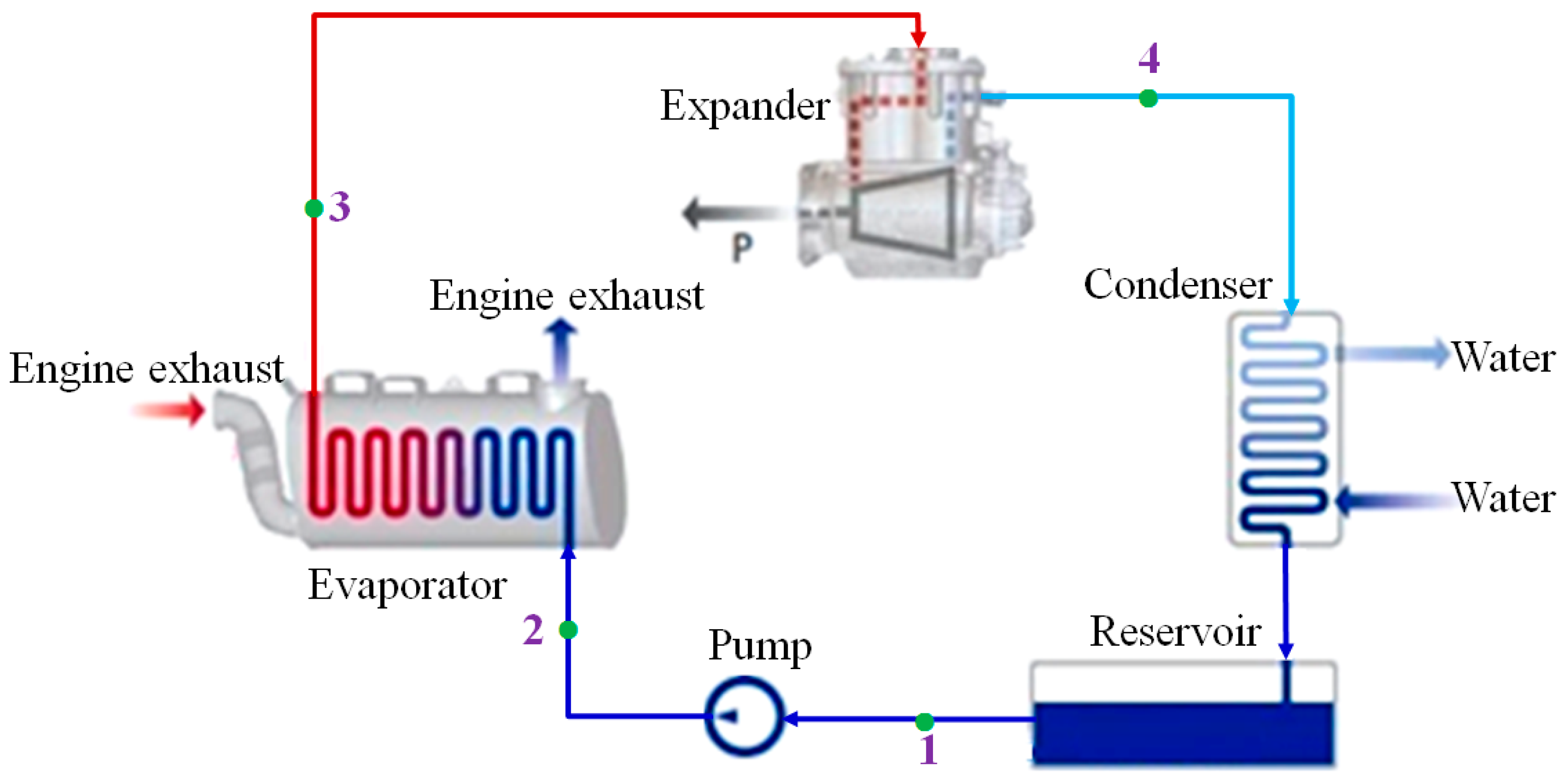
At present, most commercial ORC plants exhibit a simple architecture due to the less component and relatively low cost [36]. Hence, the simulation model is developed for a simple ORC system in this study. The Schematic diagram of simple ORC system is shown in Figure 2.
The system consists of an evaporator, a condenser, an expander, a feed pump and a reservoir. At the beginning, the exhaust gas exchanges heat with the high-pressure liquid state organic refrigerant in the evaporator, then the exhaust gas is released through evaporator into the atmosphere. Meanwhile, the refrigerant turns into high-temperature and high-pressure gas and soon enters expander to produce useful work. Later, the temperature and pressure of the refrigerant drop, the refrigerant exhausted from the expander goes into the condenser to exchange heat with the coolant (namely water). Subsequently, the cooled refrigerant condenses into liquid state in the condenser and flows into the reservoir. The refrigerant is pressurized into a high-pressure liquid state using the feed pump and flows into the evaporator to absorb the heat from engine exhaust. So far, the whole process is completed.
Figure 3 is the T-s diagram of the simple ORC system. Process 1~2 is the actual pressurization process by feed pump. Process 2~3 is the isobaric endothermic process of the refrigerants in the evaporator. Process 3~4 is the isentropic expansion process in the expander, while the Process 3~4 is the actual expansion process. Process 4~1 is the isobaric condensation process in the condenser. The selection of organic refrigerants has an important impact on thermodynamic performances of the ORC system. R245fa is selected as the working fluid for this study [37,38,39,40].
3. Numerical Simulation Model of Simple ORC System
The simple ORC system proposed in this paper is modeled refer to a case of waste heat recovery system in GT-Suite software. GT-Suite is the industry-leading simulation tool with capabilities and libraries aimed at a wide variety of applications in automotive engineering and beyond. It includes all of the components needed to model any Rankine waste heat recovery system, such as evaporators, condensers, recuperators, pumps, piston expanders, turbines, etc. The numerical simulation study about the ORC system is highly beneficial for our research group to improve the actual ORC test bench built in our lab.
3.1. Evaporator and Condenser Models
The evaporator serves to transfer heat from the exhaust of stationary CNG engine to the refrigerant. The condenser serves to reject heat from the refrigerant to the coolant. They are both two-phase heat exchangers, including three heat transfer zones: liquid zone, two-phase zone and vapor zone. The evaporator is a shell/tube type in this paper, while the condenser is a plate type. Simulation models of the evaporator and condenser are based on detailed structural parameters shown in Table 2. Other important parameters like exhaust gas mass flow rate, exhaust temperature at the inlet of evaporator, coolant volumetric flow rate, coolant inlet temperature, refrigerant mass flow rate and so on are set to the boundary conditions of the numerical simulation model.
3.1.1. Heat Transfer Coefficient of the Refrigerant in Evaporator
Both for liquid and vapor single zones, the heat transfer coefficient of the refrigerant are all defined by the Dittus-Boelter equation below [41]:
This is valid for:
where, is the heat transfer coefficient, is Reynolds number which can be calculated using the following equation:
is Prandtl number which can be calculated by using the Equation (4)
is fluid thermal conductivity, is the diameter of the tube which is selected as characteristic length, is the length of the tube.
In the two-phase zone, the evaporation heat transfer process between refrigerant and tube wall is modeled by Shah_Thome correlation which is the largest value among the following four expressions (namely, from Equation (5) to Equation (8)) [42]:
Here, is the heat transfer coefficient as calculated by Dittus-Boelter with liquid property inputs.
is boiling number which can be calculated using the following equation:
F is constant, if Bo > 0.0011, F = 0.064, if not F = 0.067
is liquid Froude number which can be calculated by using the Equation (10), if , , if not .
can be calculated by using the Equation (11):
where, x is the mass steam quality.
While the condensation heat transfer process between refrigerant and tube wall is modeled by Shah correlation as Equations (12) and (13) [33]:
where, is single phase liquid Nusselt number and it can be calculate by using the Equation (13):
is reduced pressure and it is the ratio between actual pressure and critical pressure. This is valid for:
3.1.2. Heat Transfer Coefficient of the Refrigerant in Condenser
For the condenser in this paper, the heat transfer coefficient of the refrigerant in single zone is also defined by the Dittus-Boelter equation below:
The difference between Equations (2) and (14) is the exponent of the Prandtl number. The exponent is 0.4 for heating while 0.3 for cooling because of the variation of viscosity with temperature. In the two-phase zone, the evaporation heat transfer process between refrigerant and tube wall is modeled by Kandlikar correlation as Equations (15) and (16) [43]:
while the condensation heat transfer process between refrigerant and tube wall is modeled by the_Lin correlation as Equation (17) [44]:
In Equation (17), this equivalent Reynolds number formulation is used:
3.2. Pump and Expander Models
In the ORC simulation model, a simple positive displacement pump is selected, since the individual performance of pump is beyond the concerns in our study. For simplicity, the volumetric efficiency is set to 1.0. The displacement we choose is equal to 10 cm3/r. The isentropic efficiency is set to 0.8. The pump speed is calculated using the follow equation:
where, is the refrigerant mass flow rate, is the refrigerant density in the pump inlet, is the displacement of pump, is the volumetric efficiency of pump.
In this paper, the “TurbPosDispRefrig” template of the GT-Suite software is used to simulate a kind of single screw expander developed and manufactured independently by the Beijing University of Technology. This template represents a simple positive displacement, volumetric efficiency based expander. Therefore, the same logic will be used for the expander as is used for the pump. The volumetric efficiency and isentropic efficiency of the expander are set to 1.0 and 0.8., respectively. In addition, the displacement of the expander is set to 150 cm3/r. The speed of pump and expander corresponding to the ten operating conditions of stationary CNG engine can be calculated by using the Equation (19). Besides, reservoir is directly added to the simple ORC system model, and given a volume of 3.5 L. With this, the building process of simulation model is completed.
Figure 4 presents the waste heat recovery system combined with the exhaust of stationary CNG engine. In Figure 4, “Evaporator_slave” is the high temperature resources channel (namely the engine exhaust), while “Evaporator_master” is the refrigerant channel. Similarly, “Condenser_slave” is the coolant channel and “Condenser_master” is the refrigerant channel.
3.3. Model Calibration and Validation
In our lab, we have already conducted some preliminary experiments with the ORC system, but system performance still requires optimization. Therefore, there is no effective experimental data to validate the simulation model. In addition, the waste heat of engine, refrigerant and components in ORC system are all different from the data of open literature, so by using cross-comparisons is difficult to realize validation. For example, Cipollone et al. [45] performed an experimental system to recover heat from the exhaust gases of engine. The refrigerant under investigation was a mixture of R236fa and 5% of polyol ester oil. Moreover, the sliding vane machines were chose as the expander and pump of ORC system. Zhang et al. [46] built an ORC system test bench for waste heat recovery from diesel engine exhaust. A spiral-tube type evaporator, an aluminum multi-channel parallel type condenser and a single screw expander had been used in the experimental system. The power output of diesel engine ranges from 140 kW to 250 kW. Fu et al. [47] designed and constructed a 250 kW ORC experimental system, consisting of a pump, preheater, evaporator, turbine, generator, condenser, as well as hot and cooling water circulation systems. The temperature of high temperature source and mass flow rate of working fluid were constant. However, in order to ensure the rationality of ORC system, the calibration and validation process is as follows.
3.3.1. Models Calibration
As heat exchangers in the ORC system, the evaporator and condenser have key effect on the ORC system performance. Especially, the evaporator is used to couple the stationary CNG engine with ORC system, so it is necessary to calibrate the heat exchangers. Figure 5 and Figure 6 depict the temperature profiles of the evaporator and condenser at the engine rated operating condition, respectively.
According to the tutorials of GT-Suite software, for the evaporator model, the temperature difference between wall and refrigerant should be no more than 25% of the total temperature difference between exhaust and refrigerant in the two-phase zone of refrigerant, while for the condenser model, the temperature difference between refrigerant and wall should be no more than 25% of the total temperature difference between refrigerant and coolant in the two-phase zone of refrigerant. The calculation results at the engine rated operating condition are listed in Table 3 and Table 4. Similarly, the temperature profiles of heat exchangers are all calibrated at other engine operating conditions, which indicate that the simulation model of heat exchangers are reasonable.
One last check is to verify that the assumption of 3.5 L for the reservoir is reasonable. According to the simulation results, the total system volume is 16.8 L. This means that the reservoir occupies 20.8% of the system volume. This is a good fit to the assumption (20%–30%) [48].
3.3.2. Energy and Mass Balance Validation of the ORC System
A proper system model should be in good energy balance [49]. In the ORC system, energy can change from one form to another but the total amount of energy remains constant, which can be expressed as Equation (20):
where is the overall energy input rate of the ORC system, while is the overall energy output rate of the ORC system.
In the model validations, energy loss in each component as well as pipelines is neglected. Therefore, for the simple ORC system in this paper, the energy balance is given in Equation (21):
where, is the heat transfer rate of engine exhaust in evaporation process, is the energy consumption rate of feed pump, is the heat transfer rate of refrigerant in condensation process. is the expansion power.
In this paper, ten operating conditions of stationary CNG engine are selected and the energy balance calculation results are given in Figure 7. As shown in Figure 7, the modeled energy balance is not zero under all the operating conditions of the stationary CNG engine. The reason can be explained as follows: the energy balance Equation (21) is given on the condition that the energy loss in each component as well as the pipelines is neglected. However, for the running state of the ORC simulation model, the heat losses exist in the heat exchangers and pipelines. Moreover, the maximum energy deviation is only 0.5 kW, so the energy of the ORC system is well balanced. Besides, the mass in circuit of ORC simulation model is unchanged, and the mass of ORC system is thus in good balance, too. So far, the simulation model of ORC system is thought to be reliable and reasonable.
4. Results and Discussion
4.1. Running State of ORC System
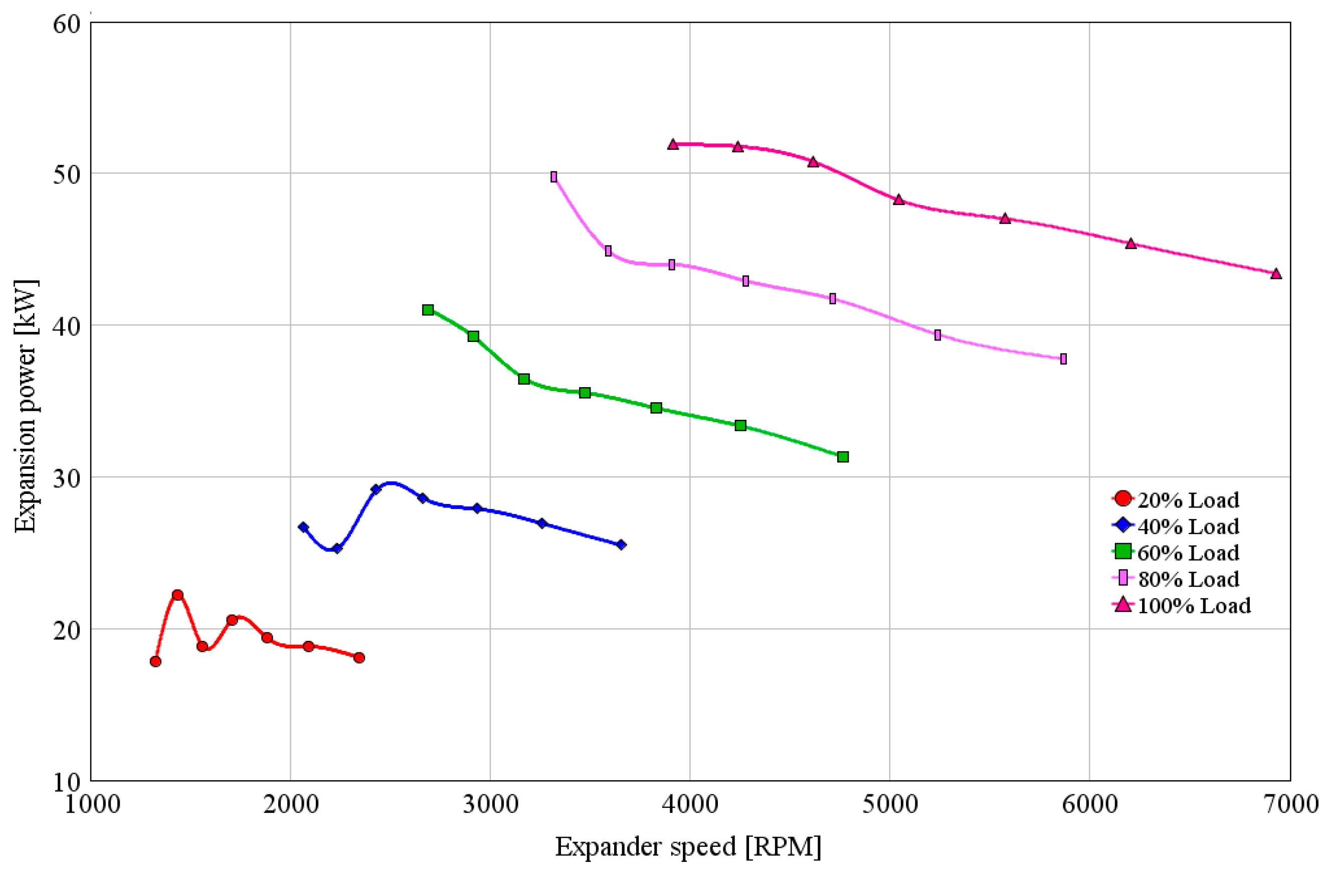
Depending on the various operating conditions of the engine, the exhaust waste heat exhibits variation. The power output characteristic of expander is analyzed for five important operating conditions which are successively 20%, 40%, 60%, 80%, and 100% engine load. Therein, 100% engine load is the rated condition of the engine. When the engine load is constant, the seven expander speeds are selected based on the variation of evaporation pressure.
Figure 8 illustrates the variation of expansion power with the expander speed at different engine loads. As seen in the figure, the expansion power decreases with expander speed in the engine’s medium- and high-load regions (from 60% engine load to 100% engine load). While in the engine’s low-load regions (from 20% engine load to 40% engine load), the expansion power fluctuates with expander speed.
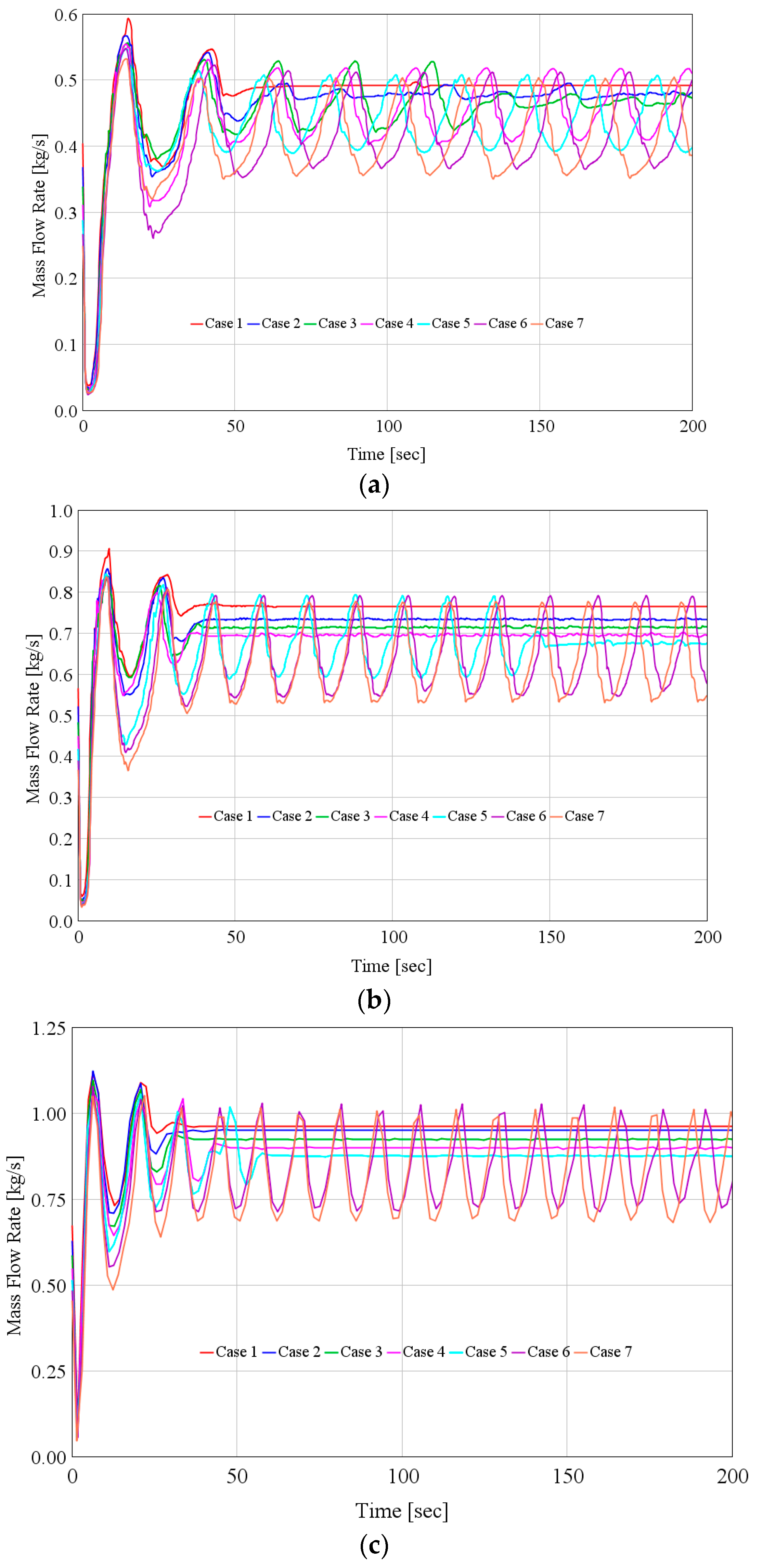
In order to further analyze the fluctuation and determine the running state of the simple ORC system, the dynamic characteristics of refrigerant mass flow rate in expander are analyzed for all the five engine operating conditions at different expander speed. In Figure 9, the expander speeds of the seven cases are corresponding to that of in Figure 8.
As shown in Figure 9, when the operating condition of the stationary CNG engine is constant, the fluctuation of refrigerant mass flow rate increases with the decrease of expander speed (from case 1 to case 7), especially in the engine’s low-load regions (from 20% engine load to 40% engine load), the fluctuation is more obvious. The reason can be explained as follows: the engine from start to run in the low-load region, the available exhaust energy rate is relatively low and occasionally undulates seriously which leads to the fluctuation of refrigerant mass flow rate. On the other hand, because the precise and complicated control strategy are not applied to the ORC system, the dynamic matching characteristics between refrigerant mass flow rate and expander speed is gradually degraded with the decrease of engine load. As shown in Figure 9a,e, the refrigerant mass flow rate is always keeping stable in the seven cases of 100% engine load. Whereas, the refrigerant mass flow rate is stable only in the case 1 of 20% engine load. According to the analysis, the precise and complicated control strategy should be applied to the ORC system, but this will increase the operation cost of ORC system which affects the engineering application.
Furthermore, the fluctuation of refrigerant mass flow rate will lead to the ORC system instability and even damage the system components, such as evaporator and expander. Evaporation pressure is determined by the flow resistance along the pipe of ORC system [33]. So the fluctuation of refrigerant mass flow rate results in the unstable evaporation pressure. Moreover, the ORC system cannot run efficiently due to the unstable evaporation pressure.
Based on the above analysis, the simple ORC system cannot work in the whole engine operating conditions. Therefore, in order to ensure the ORC system to run efficiently and smoothly, the exhaust energy can be recovered in the engine’s medium- and high-load regions (from 60% engine load to 100% engine load); correspondingly, the ORC system is in power state. While the exhaust energy cannot be recovered in the low-load region (less than 60% engine load) of stationary CNG engine, the ORC system is in stop state.
In Figure 10, for the power state of ORC system, the heat transfer rate in evaporator and exhaust energy rate all increase with engine torque (namely engine load). At the rated operating condition of the stationary CNG engine, the heat transfer rate and exhaust energy rate can reach up to 440.3 kW and 1195.9 kW, respectively. Hence, the evaporator waste heat recovery efficiency (the ratio of heat transfer rate in evaporator to exhaust energy rate) is 36.8%.
4.2. Performance Analysis of the Simple ORC System
Figure 11 shows the variation of exhaust temperature at outlet of the evaporator with evaporation pressure and engine load. The outlet exhaust temperature increases with engine load and evaporation pressure.
Overall, the exhaust temperature at outlet of the evaporator ranges from 468 K to 491 K for the existing shell/tube evaporator, which means that there is still some residual waste heat energy which can be recovered from the engine exhaust. Therefore, to improve the evaporator waste heat recovery efficiency, the heat transfer area of the evaporator should be increased in the future study.
The net power output of ORC system is the difference between expansion power and pump power . The variation tendency of the net power output rate with expander speed and engine load is shown in Figure 12. The net power output increases with the engine load. This increase occurs because the heat transfer rate dramatically increases with engine torque, as shown in Figure 10. Besides, when the engine load is constant, the net power output decreases with the increase of expander speed. When the expander speed is 4242 rpm, the net power output is the maximum (48.6 kW) at the engine rated condition.
4.3. Performance Analysis of the Stationary CNG Engine-ORC Combined System
In this paper, the concept of a “stationary CNG engine-ORC combined system” is defined, in the combined system, the Otto cycle (for the stationary CNG engine) is the topping cycle, and the Rankine cycle (for the simple ORC system) is the bottoming cycle. To evaluate the performances of stationary CNG engine-ORC combined system, the thermal efficiency of the combined system can be expressed as:
where, is the fuel combustion energy, which can be calculated using the fuel consumption rate and fuel lower heating value.
The BSFC of the combined system can be expressed as:
where, is fuel consumption rate of stationary CNG engine.
Figure 13 shows the variation of thermal efficiency and BSFC of the stationary CNG engine with engine load (from 60% engine load to 100% engine load).
As for the stationary CNG engine-ORC combined system, the thermal efficiency is shown in Figure 14. Comparing Figure 14 and Figure 13 shows that the thermal efficiencies of combined system are all higher than that of stationary CNG engine for the same engine load. As shown in Figure 14, the thermal efficiency of the combined system increases with engine load and evaporation pressure. When the evaporation pressure is 29.4 bar, the maximum thermal efficiency of combined system is 41.0% at the engine rated condition, which is higher than that of stationary CNG engine by 5.0%. Howerer, in the engine’s high-load regions (from 90% engine load to 100% engine load), the increment of thermal efficiency of combined system is slight. Therefore, compared with the stationary CNG engine, the combined system can effectively improve the thermal efficiency.
The variation of the BSFC of the combined system is shown in Figure 15. Through comparison of the BSFC between the stationary CNG engine and the combined system, the BSFC of the combined system are all lower than that of the stationary CNG engine. When evaporation pressure is 29.4 bar, the minimum BSFC of the combined system is 176.9 g/(kW·h) at engine rated condition, which is lower than that of stationary CNG engine by 4.0%.
5. Conclusions and Outlook
In this study, a simple ORC system is modeled for a stationary CNG engine to recover the exhaust heat. The thermodynamic performances of the ORC system and the combined system have been conducted and main conclusions can be drawn as follows:
- (1)
- The simple ORC system cannot work under all the engine operating conditions. For the engine’s medium- and high-load regions (from 60% engine load to 100% engine load), the ORC system can be in power state. For the engine’s the low-load region (less than 60% engine load), the ORC system can be in stop state.
- (2)
- When the engine operating conditions are constant, the effects of the expander speed on expansion power and expander stability are opposite. Whereas, the conflict between expansion power and expander stability weakens with the increase of engine load. Thus, in order to ensure the ORC system effectively recover exhaust heat from the stationary CNG engine, expander speed should be regulated for the corresponding operating conditions of the stationary CNG engine.
- (3)
- Compared with the stationary CNG engine, the combined system has an advantage in fuel economy. When evaporation pressure is 29.4 bar, the maximum thermal efficiency of combined system is 41.0% at the engine rated condition, which is higher than that of stationary CNG engine by 5.0%; the minimum BSFC of the combined system is 176.9 g/(kW·h) at the engine rated condition, which is lower than that of stationary CNG engine by 4.0%.
In this research, we have done some simulation work for a simple ORC system. The simulation results show that the exhaust temperature at the outlet of the evaporator ranges from 468 K to 491 K for the existing shell/tube evaporator. In order to improve the evaporator waste heat recovery efficiency, the heat transfer area of the evaporator should be increased in a future study. Moreover, an integrated simulation model of the combined stationary CNG engine–ORC system will be built, and then the performances and operation mode analysis of combined system will be studied based on the integrated simulation model. For the operation mode of the combined system, four operation modes will be proposed and defined: startup mode, idle mode, power mode and stop mode. In order to ensure the combined system to run efficiently under the four operation modes, we will perform an in depth optimization and synergy control strategy work.
Acknowledgments
This work was sponsored by the National Natural Science Foundation of China (Grant No. 51376011), Projects of International Cooperation and Exchanges NSFC (Grant No. 51611130193), the Beijing Natural Science Foundation Program (Grant No. 3152005), Scientific Research Key Program of Beijing Municipal Commission of Education (Grant No. KZ201410005003), the National Basic Research Program of China (973 Program) (Grant No. 2013CB228306), the Project of fifteenth Scientific Research Foundation for Graduate Students in Beijing University of Technology (Grant No. ykj-2016-00454 and ykj-2016-00292).
Author Contributions
Songsong Song wrote the main body of the paper; Hongguang Zhang, Jingfu Wang and Baofeng Yao revised the paper; Hongda Liu, Rui Zhao and Fanxiao Meng performed the computational calculations. All authors read and approved the manuscript. The authors would like to thank the reviewers for their valuable comments on this research.
Conflicts of Interest
The authors declare no conflict of interest.
Nomenclature
| fuel consumption (kg/h) | |
| specific heat at constant pressure(kJ/kg·K) | |
| character length (m) | |
| energy rate (kg/h) | |
| mass flux (kg/m2·s) | |
| g | acceleration due to gravity (m/s2) |
| heat transfer coefficient (W/m2·K) | |
| thermal conductivity (W/m·k) | |
| L | length of tube (m) |
| refrigerant mass flow rate (kg/s) | |
| P | pressure (MPa) |
| heat transfer rate (kW) | |
| heat flux (kW/m2) | |
| entropy (kJ/kg·K) | |
| temperature (K) | |
| velocity (m/s) | |
| displacement | |
| power (kW) | |
| steam quality |
Greek Letters
| mass density (kg/m3) | |
| efficiency (%) | |
| dynamic viscosity (pa.s) |
Subscript
| c | condenser |
| com | combined system |
| dis | displacement |
| exh | exhaust |
| e | expander |
| en | engine |
| eq | equivalent |
| ev | evaporator |
| f | fuel |
| fo | liquid only |
| in | inlet |
| l | liquid |
| n | net |
| out | outlet |
| p | pump |
| rd | reduced |
| v | vapour |
| V | volumetric |
Acronyms
| BSFC | brake specific fuel consumption |
| CNG | compressed natural gas |
| ICE | internal combustion engine |
| ORC | organic Rankine cycle |
| ODP | ozone depletion potential |
| GWP | global warming potential |
References
- Bai, S.Q.; Lu, H.L.; Wu, T.; Yin, X.L.; Shi, X.; Chen, L.D. Numerical and experimental analysis for exhaust heat exchangers in automobile thermoelectric generators. Case Stud. Therm. Eng. 2014, 4, 99–112. [Google Scholar] [CrossRef]
- Aghaali, H.; Ångström, H.E. A review of turbocompounding as a waste heat recovery system for internal combustion engines. Renew. Sustain. Energy Rev. 2015, 49, 813–824. [Google Scholar] [CrossRef]
- Serrano, J.R.; Olmeda, P.; Arnau, F.J.; Dombrovsky, A.; Smith, L. Turbocharger heat transfer and mechanical losses influence in predicting engines performance by using one-dimensional simulation codes. Energy 2015, 86, 204–218. [Google Scholar] [CrossRef]
- Capata, R.; Toro, C. Feasibility analysis of a small-scale ORC energy recovery system for vehicular application. Energy Convers. Manag. 2014, 86, 1078–1090. [Google Scholar] [CrossRef]
- He, C.; Liu, C.; Gao, H.; Xie, H.; Li, Y.R.; Wu, S.Y.; Xu, J.L. The optimal evaporation temperature and working fluids for subcritical organic Rankine cycle. Energy 2012, 38, 136–143. [Google Scholar] [CrossRef]
- Zhang, J.H.; Feng, J.C.; Zhou, Y.L.; Fang, F.; Yue, H. Linear active disturbance rejection control of waste heat recovery systems with organic Rankine cycles. Energies 2012, 5, 5111–5125. [Google Scholar] [CrossRef]
- Uusitalo, A.; Honkatukia, J.; Turunen-Saaresti, T.; Larjola, J. A thermodynamic analysis of waste heat recovery from reciprocating engine power plants by means of organic Rankine cycles. Appl. Energy 2014, 70, 33–41. [Google Scholar] [CrossRef]
- Yang, F.B.; Zhang, H.G.; Song, S.S.; Bei, C.; Wang, H.J.; Wang, E.H. Thermoeconomic multi-objective optimization of an organic Rankine cycle for exhaust waste heat recovery of a diesel engine. Energy 2015, 93, 2208–2228. [Google Scholar] [CrossRef]
- Shokati, N.; Ranjbar, F.; Yari, M. Exergoeconomic analysis and optimization of basic, dual-pressure and dual-fluid ORCs and Kalina geothermal power plants: A comparative study. Renew. Energy 2015, 83, 527–542. [Google Scholar] [CrossRef]
- Bernardo, P.; Joaquín, N.E.; Molés, F.; Mota-Babiloni, A. Experimental study of an ORC (organic Rankine cycle) for low grade waste heat recovery in a ceramic industry. Energy 2015, 85, 534–542. [Google Scholar]
- Song, J.; Gu, C.W. Analysis of ORC (Organic Rankin e Cycle) systems with pure hydrocarbons and mixtures of hydrocarbon and retardant for engine waste heat recovery. Appl. Energy 2015, 89, 693–702. [Google Scholar] [CrossRef]
- Panesar, A.S.; Morgan, R.E.; Nicolas, D.D.; Miché, ND.D.; Morgan, R.H. Working fluid selection for a subcritical bottoming cycle applied to a high exhaust gas recirculation engine. Energy 2013, 60, 388–400. [Google Scholar] [CrossRef]
- Wang, J.F.; Yan, Z.Q.; Wang, M.; Li, M.Q.; Dai, Y.P. Multi-objective optimization of an organic Rankine cycle (ORC) for low grade waste heat recovery using evolutionary algorithm. Energy Convers. Manag. 2013, 71, 146–158. [Google Scholar] [CrossRef]
- Hatami, M.; Ganji, D.D.; Gorji-Bandpy, M. Experimental and numerical analysis of the optimized finned-tube heat exchanger for OM314 diesel exhaust exergy recovery. Energy Convers. Manag. 2015, 97, 26–41. [Google Scholar] [CrossRef]
- Xiao, L.; Wu, S.Y.; Yi, T.T.; Liu, C.; Li, Y.R. Multi-objective optimization of evaporation and condensation temperatures for subcritical organic Rankine cycle. Energy 2015, 83, 723–733. [Google Scholar] [CrossRef]
- Wang, E.H.; Zhang, H.G.; Fan, B.Y.; Wu, Y.T. Optimized performances comparison of organic Rankine cycles for low grade waste heat recovery. J. Mech. Sci. Technol. 2012, 26, 2301–2312. [Google Scholar] [CrossRef]
- Mago, P.J.; Chamra, L.M.; Srinivasan, K.; Somayaji, C. An examination of regenerative organic Rankine cycles using dry fluids. Appl. Energy 2008, 28, 998–1007. [Google Scholar] [CrossRef]
- Zhang, J.; Zhang, H.G.; Yang, K.; Yang, F.B.; Wang, Z.; Zhao, G.Y.; Liu, H.; Wang, E.H.; Yao, B.F. Performance analysis of regenerative organic Rankine cycle (RORC) using the pure working fluid and the zeotropic mixture over the whole operating range of a diesel engine. Energy Convers. Manag. 2014, 84, 282–294. [Google Scholar] [CrossRef]
- Shu, G.Q.; Liu, L.N.; Tian, H.; Wei, H.Q.; Yu, G.P. Parametric and working fluid analysis of a dual-loop organic Rankine cycle (DORC) used in engine waste heat recovery. Appl. Energy 2014, 113, 1188–1198. [Google Scholar] [CrossRef]
- Yang, K.; Zhang, H.G.; Song, S.S.; Yang, F.B.; Liu, H.; Zhao, G.Y.; Zhang, J.; Yao, B.F. Effects of degree of superheat on the running performances of organic Rankine cycle (ORC) waste heat recovery system for diesel engine under engine various operating conditions. Energies 2014, 7, 2123–2145. [Google Scholar] [CrossRef]
- Steven, L.; Henk, H.; Martijn van den, B.; Bruno, V.; Michel, D.P. Review of organic Rankine cycle (ORC) architectures for waste heat recovery. Renew. Sustain. Energy Rev. 2015, 47, 448–461. [Google Scholar]
- Zhang, H.G.; Wang, E.H.; Fan, B.Y. Heat Transfer Analysis of a Finned-tube Evaporator for Engine Exhaust Heat Recovery. Energy Convers. Manag. 2013, 65, 438–447. [Google Scholar] [CrossRef]
- Mastrullo, R.; Mauro, A.W.; Revellin, R.; Viscito, L. Modeling and optimization of a shell and louvered fin mini-tubes heat exchanger in an ORC powered by an internal combustion engine. Energy Convers. Manag. 2015, 101, 697–712. [Google Scholar] [CrossRef]
- Cipollone, R.; Bianchi, G.; Battista, D.D.; Fatigati, F. Experimental and numerical analyses on a plate heat exchanger with phase change for waste heat recovery at off-design conditions. In Proceedings of the 33rd Uit Heat Transfer Conference, L’Aquila, Italy, 22–24 June 2015. [Google Scholar]
- Bala, E.J.; O’Callaghan, P.W.; Probert, S.D. Influence of organic working fluids on the performance of a positive-displacement pump with sliding vanes. Appl. Energy 1985, 20, 153–159. [Google Scholar] [CrossRef]
- Yang, K.; Zhang, H.G.; Song, S.S.; Zhang, J.; Wu, Y.T.; Zhang, Y.Q.; Wang, H.J.; Chang, Y.; Bei, C. Performance analysis of the vehicle diesel engine-ORC combined system based on a screw expander. Energies 2014, 7, 3400–3419. [Google Scholar] [CrossRef]
- Cipollone, R.; Bianchi, G.; Battista, D.D.; Contaldi, G.; Murgia, S. Mechanical energy recovery from low grade thermal energy sources. Energy Procedia 2014, 45, 121–130. [Google Scholar] [CrossRef]
- Wang, E.H.; Zhang, H.G.; Fan, B.Y.; Ouyang, M.G.; Yang, K.; Yang, F.Y.; Li, X.J.; Wang, Z. 3D numerical analysis of exhaust flow inside a fin-and-tube evaporator used in engine waste heat recovery. Energy 2015, 82, 800–812. [Google Scholar] [CrossRef]
- Song, P.P.; Wei, M.S.; Liu, Z.; Zhao, B. Effects of suction port arrangements on a scroll expander for a small scale ORC system based on CFD approach. Appl. Energy 2015, 150, 274–285. [Google Scholar] [CrossRef]
- Bianchi, G.; Fatigati, F.; Murgia, S.; Cipollone, R.; Contaldi, G. Modeling and experimental activities on a small-scale sliding vane pump for ORC-based waste heat recovery applications. Energy Procedia 2016, 101, 1240–1247. [Google Scholar] [CrossRef]
- Wei, D.H.; Lu, X.S.; Lu, Z.; Gu, J.M. Dynamic modeling and simulation of an organic Rankine cycle (ORC) system for waste heat recovery. Appl. Therm. Eng. 2008, 28, 1216–1224. [Google Scholar] [CrossRef]
- Shi, R.Q.; He, T.Q.; Peng, J.; Zhang, Y.J.; Zhuge, W.L. System design and control for waste heat recovery of automotive engines based on organic Rankine cycle. Energy 2016, 102, 276–286. [Google Scholar] [CrossRef]
- Xie, H.; Yang, C. Dynamic behavior of Rankine cycle system for waste heat recovery of heavy duty diesel engines under driving cycle. Appl. Energy 2013, 112, 130–141. [Google Scholar] [CrossRef]
- Tian, G.H.; Zhang, Y.; Roskilly, T. Semi-Dynamic simulation of ORC based diesel engine WHR system. Energy Procedia 2014, 61, 695–699. [Google Scholar] [CrossRef]
- Maraver, D.; Royo, J.; Lemort, V.; Quoilin, S. Systematic optimization of subcritical and transcritical organic Rankine cycles (ORCs) constrained by technical parameters in multiple applications. Appl. Energy 2014, 117, 11–29. [Google Scholar] [CrossRef]
- Quoilin, S.; Martijn Van Den, B.; Declaye, S.B.; Dewallef, P.; Lemort, V. Techno-economic survey of organic Rankine cycle (ORC) systems. Renew. Sustain. Energy Rev. 2013, 22, 168–186. [Google Scholar] [CrossRef]
- Wang, E.H.; Zhang, H.G.; Fan, B.Y.; Ouyang, M.G.; Zhao, Y.; Mu, Q.H. Study of working fluid selection of organic Rankine cycle (ORC) for engine waste heat recovery. Energy 2011, 36, 3406–3418. [Google Scholar] [CrossRef]
- Xu, J.L.; Yu, C. Critical temperature criterion for selection of working fluids for subcritical pressure Organic Rankine cycles. Energy 2014, 74, 719–733. [Google Scholar] [CrossRef]
- Wang, J.L.; Zhao, L.; Wang, X.D. An experimental study on the recuperative low temperature solar Rankine cycle using R245fa. Appl. Energy 2012, 94, 34–40. [Google Scholar] [CrossRef]
- You, R.L.; Jian, N.W.; Mei, T.D. Influence of coupled pinch point temperature difference and evaporation temperature on performance of organic Rankine cycle. Energy 2012, 42, 503–509. [Google Scholar]
- Yang, S.M.; Tao, W.Q. Heat Transfer, 4th ed.; Higher Education Press: Beijing, China, 2008. [Google Scholar]
- John, G.C.; Johnr, T. Convective Boiling and Condensation, 3th ed.; Oxford University Press: New York, NY, USA, 1994. [Google Scholar]
- Kandlikar, S.G. A General correlation for saturated two-phase flow boiling heat transfer inside horizontal and vertical tubes. ASME. J. Heat Transf. 1990, 112, 219–228. [Google Scholar] [CrossRef]
- Yan, Y.Y.; Lio, H.C.; Lin, T.F. Condensation heat transfer and pressure drop of refrigerant R134a in a plate heat exchanger. Int. J. Heat Mass Trans. 1999, 42, 993–1006. [Google Scholar] [CrossRef]
- Cipollone, R.; Bianchi, G.; Gualtieri, A.; Battista, D.D.; Mauriello, M.; Fatigati, F. Development of an organic Rankine cycle system for exhaust energy recovery in internal combustion engines. In Proceedings of the 33rd Uit Heat Transfer Conference, L’Aquila, Italy, 22–24 June 2015. [Google Scholar]
- Zhang, Y.Q.; Wu, Y.T.; Xia, G.D.; Ma, C.F.; Ji, W.N.; Liu, S.W.; Yang, K.; Yang, F.B. Development and experimental study on organic Rankine cycle system with single-screw expander for waste heat recovery from exhaust of diesel engine. Energy 2014, 77, 499–508. [Google Scholar] [CrossRef]
- Fu, B.R.; Lee, Y.R.; Hsieh, J.C. Design construction and preliminary results of a 250-kW organic Rankine cycle system. Appl. Therm. Eng. 2015, 80, 339–346. [Google Scholar] [CrossRef]
- Gamma Technologies Inc. GT-Suite Air Conditioning and Waste Heat Recovery Tutorials; Gamma Technologies Inc.: Westmont, IL, USA, 2012; pp. 141–160. [Google Scholar]
- Yu, G.P.; Shu, G.Q.; Tian, H.; Wei, H.Q.; Liu, L.N. Simulation and thermodynamic analysis of a bottoming organic Rankine cycle (ORC) of diesel engine (DE). Energy 2013, 51, 281–290. [Google Scholar] [CrossRef]
Figure 1.
Exhaust temperature and mass flow rate of the stationary compressed natural gas (CNG) engine.
Figure 1.
Exhaust temperature and mass flow rate of the stationary compressed natural gas (CNG) engine.

Figure 2.
Schematic diagram of simple ORC system.

Figure 3.
T-s diagram of the simple ORC system.

Figure 4.
Numerical simulation model of the simple ORC system.

Figure 5.
Temperature profile of the evaporator.

Figure 6.
Temperature profile of the condenser.

Figure 7.
Energy balances of the ten operating conditions.

Figure 8.
Variation of expansion power with engine load.

Figure 9.
The fluctuation of refrigerant mass flow rate in the expander at different engine load: (a) 20% engine load; (b) 40% engine load; (c) 60% engine load; (d) 80% engine load; and (e) 100% engine load.
Figure 9.
The fluctuation of refrigerant mass flow rate in the expander at different engine load: (a) 20% engine load; (b) 40% engine load; (c) 60% engine load; (d) 80% engine load; and (e) 100% engine load.


Figure 10.
Power state of the ORC system.

Figure 11.
Exhaust temperature at the outlet of evaporator.

Figure 12.
Net power output of the ORC system.

Figure 13.
Thermal efficiency and BSFC of the stationary CNG engine.

Figure 14.
Thermal efficiency of the combined system.

Figure 15.
BSFC of the combined system.


Table 1.
Main performance parameters of the stationary CNG engine.
| Items | Parameters | Units |
|---|---|---|
| Rated power | 1100 | kW |
| Maximum torque | 6969 | N·m |
| Engine speed | 1500 | rpm |
| Displacement | 57.87 | L |
| Cylinder number | 12 | - |
| Air intake type | Turbocharged and intercooled | - |
| Stroke and cylinder bore | 210 × 171 | mm |
| Compression ratio | 10.8 | - |
Table 2.
Geometric parameters of the heat exchangers.
| Heat Exchangers | Items | Parameters | Units |
|---|---|---|---|
| Evaporator | Number of tubes | 100 | - |
| Tube length | 850 | mm | |
| Circular channel inner diameter | 7 | mm | |
| Number of channels (in one tube) | 1 | - | |
| Shell diameter | 150 | mm | |
| Condenser | Plate length | 300 | mm |
| Plate width | 200 | mm | |
| Number of channels | 45 | - | |
| Channel height | 3 | mm |
Table 3.
Temperature in two-phase zone of the evaporator.
| Location | Refrigerant Temperature | Wall Temperature | Exhaust Gas Temperature | Deviation |
|---|---|---|---|---|
| 0.55 | 396.8 K | 413.1 K | 593.1 K | 8.3% |
| 0.60 | 396.8 K | 413.1 K | 611.9 K | 7.6% |
| 0.64 | 396.8 K | 415.9 K | 632.6 K | 8.1% |
| 0.69 | 396.8 K | 420.3 K | 655.1 K | 9.1% |
| 0.74 | 396.8 K | 445.9 K | 679.4 K | 17.4% |
Table 4.
Temperature in two-phase zone of the condenser.
| Location | Refrigerant Temperature | Wall Temperature | Coolant Temperature | Deviation |
|---|---|---|---|---|
| 0.53 | 326.8 K | 321.9 K | 307.0 K | 24.7% |
| 0.58 | 326.8 K | 323.2 K | 305.9 K | 17.2% |
| 0.64 | 326.8 K | 323.1 K | 304.8 K | 16.8% |
| 0.69 | 326.8 K | 322.8 K | 303.5 K | 17.1% |
| 0.75 | 326.8 K | 322.4 K | 302.2 K | 17.9% |
| 0.81 | 326.8 K | 322.0 K | 300.9 K | 18.5% |
| 0.86 | 326.8 K | 321.6 K | 299.6 K | 19.1% |
| 0.92 | 326.8 K | 321.9 K | 298.2 K | 17.1% |
© 2017 by the authors. Licensee MDPI, Basel, Switzerland. This article is an open access article distributed under the terms and conditions of the Creative Commons Attribution (CC BY) license (http://creativecommons.org/licenses/by/4.0/).
Share and Cite
MDPI and ACS Style
Song, S.; Zhang, H.; Zhao, R.; Meng, F.; Liu, H.; Wang, J.; Yao, B. Simulation and Performance Analysis of Organic Rankine Systems for Stationary Compressed Natural Gas Engine. Energies 2017, 10, 544. https://doi.org/10.3390/en10040544
AMA Style
Song S, Zhang H, Zhao R, Meng F, Liu H, Wang J, Yao B. Simulation and Performance Analysis of Organic Rankine Systems for Stationary Compressed Natural Gas Engine. Energies. 2017; 10(4):544. https://doi.org/10.3390/en10040544
Chicago/Turabian StyleSong, Songsong, Hongguang Zhang, Rui Zhao, Fanxiao Meng, Hongda Liu, Jingfu Wang, and Baofeng Yao. 2017. "Simulation and Performance Analysis of Organic Rankine Systems for Stationary Compressed Natural Gas Engine" Energies 10, no. 4: 544. https://doi.org/10.3390/en10040544
Note that from the first issue of 2016, this journal uses article numbers instead of page numbers. See further details here.