
Review on Contactless Power Transfer for Electric Vehicle Charging


Department of Electrical Engineering, Visvesvaraya National Institute of Technology, Nagpur 440010, India
*
Author to whom correspondence should be addressed.
Energies 2017, 10(5), 636; https://doi.org/10.3390/en10050636
Submission received: 25 January 2017
/
Revised: 29 March 2017
/
Accepted: 12 April 2017
/
Published: 5 May 2017
(This article belongs to the Special Issue Advanced Power Electronics and Control for Wireless Power Transfer Systems)
Abstract
:For the past few years the feasibility of contactless power transfer (CPT) is being explored extensively as a future solution for charging electric vehicles (EVs). Studies report that the main obstacles in CPT are low power efficiency, misalignment tolerance, cost, range and charging time anxiety. This paper presents a review based on existing literature of the CPT systems for EV charging. Different cases of CPT technologies, their principle of operation and equivalent circuit based analysis is carried out. A discussion on compensation strategies and their effectiveness are reviewed and discussed. The design of coil systems for some city electric cars has been referenced in general. At the end recommendations and conclusions are made based on the study and analysis of the information available in literature.
1. Introduction
Electric Vehicles (EVs) are being looked to as the future of transportation, with the objectives of reducing the emissions caused by internal combustion engine (ICE)-based vehicles and the possibility of increased well-to-wheel efficiency [1,2,3]. Electric vehicles are conventionally categorized as: (i) hybrid EVs; and (ii) pure EVs. In the case of hybrid EVs, apart from on-board DC-sources of energy such as batteries, lower sized ICEs are also used for traction power and are used to charge the on-board energy sources when required, whereas in the case of pure EVs, the on-board batteries must to be charged by receiving energy from the grid through on-board or off-board chargers. The capacity of the on-board energy source and the driving pattern affects the autonomy of the vehicle to a great extent. The capacity of an energy source can be specified in terms of specific energy density and specific power density. High energy density ensures a longer range of operation and high power density ensures the capability of delivering significantly higher current during acceleration, but for a very short time duration [4]. In practice, all particular sources lack both capabilities at the same time, so mixed/hybrid energy sources such as combination of batteries and ultra-capacitors are being considered as one possible solution. Because of their low equivalent static resistance (ESR) ultra-capacitors are able to receive energy from external sources at a much faster rate than batteries, and can later on in some cases deliver energy to the batteries for extended mobility.
It has now become compulsory to use energy from sources like photovoltaic installations and wind energy to power EV charging stations. This not only reduces the burden on the grid, but also ensures the utilization of green energy, reducing emissions [5,6,7,8,9].
For the case of on-board chargers, battery/ultra-capacitors can be charged through conductive or contactless means. Conductive charging uses wires between the utility grid supply and the charging port of an electric vehicle. Even though conductive charging is familiar, it suffers from problems like the need for connecting cables, galvanic isolation for on-board electronics, increased weight and size of chargers and the problem of safety in wet environments [10]. Due to the above reasons, interest in contactless charging has been growing in the past few years. It has advantages like no exposed wires, sockets, plugs and no fear of electric shock in wet environments [11,12,13,14]. In spite of the above advantages of contactless charging, there are certain issues to be solved, like the design of magnetic couplers with better misalignment tolerance, high efficiency with maximum power transfer capability, low stress on the devices, reduction of control technique complexity and assurance of leakage flux within the safety regulation limits.
Based on the flux generated, magnetic couplers are classified as polarized and non-polarized couplers. Polarized couplers can generate both perpendicular and parallel flux components while non-polarized couplers generate only the perpendicular component of flux. The detailed analysis of couplers was carried out in [15]. Polarized couplers require synchronized converters which increases their cost and are sensitive to angular misalignments [16], so non-polarized pads like asymmetrical circular spiral couplers are preferable for static charging to avoid synchronous converters and to improve angular misalignment tolerance. High efficiency, maximum power transfer and low stress on the devices can be obtained by using different compensation topologies and are discussed in Section 5 of this paper. Reference [17] comments on the conditions for the maximum efficiency and power output in series-series compensation topology with respect to load resistance, mutual inductance, and resonant frequency when transmitter is fed with voltage source or current source. In [17] it can be observed that in case of series-series compensation topology the power increases linearly with the coupling coefficient when supplied with a current source.
In contactless power transfer (CPT) power flow can be controlled from either or both the transmitting or receiving end. For the case of multiple receiving coils coupled with a single transmitting coil, excitation and frequency are kept constant and power flow control is achieved at the receiving end with the help of a rectifier and DC-DC converter [18]. For stationary charging as there is a single receiving coil, it is better to control from the transmitting side so that DC-DC converter at the receiving side can be eliminated there by losses in the receiving side can be reduced [19]. Transmitting side control techniques are classified as fixed frequency and variable frequency. Variable frequency control techniques can maintain unity power factor but issues of bifurcation and instability arise [20], so fixed frequency control is preferable for stationary charging and is discussed in Section 6.
As the chassis of the EV deteriorates the coil performance, aluminum plates of greater thickness than the skin depth are placed in between the chassis and coils with a ferrite core. This arrangement is known as passive shielding. If the time varying electro-magnetic field (EMF) within the surroundings of a vehicle is greater than the limit specified by International Commission on Non-ionizing Radiation Protection (ICNIRP), a reactive resonant current loop is used to decrease the EMF below the ICNIRP limits [21].
Static CPT is convenient for charging at home or office parking spots [22]. One solution proposed by researchers to decrease the weight of the on-board batteries and to improve EVs features is dynamic charging [23,24]. Research articles in the past few years also showed improvements in the limitations of CPT like increases in power transfer with high efficiency, increases in misalignment tolerance and reduction in charging time.
This paper is focused more on stationary charging and structured as follows: Section 2 presents different technologies used in CPT. Section 3 deals with inductive power transfer and the need for compensation at the transmitting and receiving side. Section 4 discusses an outline of issues in inductive coupled CPT based on existing literature. Section 5 describes the development of inductive coupled resonant CPT for EVs charging. It includes selection of compensation topology, design of coils and misalignment studies. Section 6 discusses the study of high frequency converters which are required to supply power to the resonant inductive link, their control strategy and future needs for EVs. Section 7 concludes the paper based on the information studied in the literature and presented in this review.
2. Different Technologies in Contactless Power Transfer
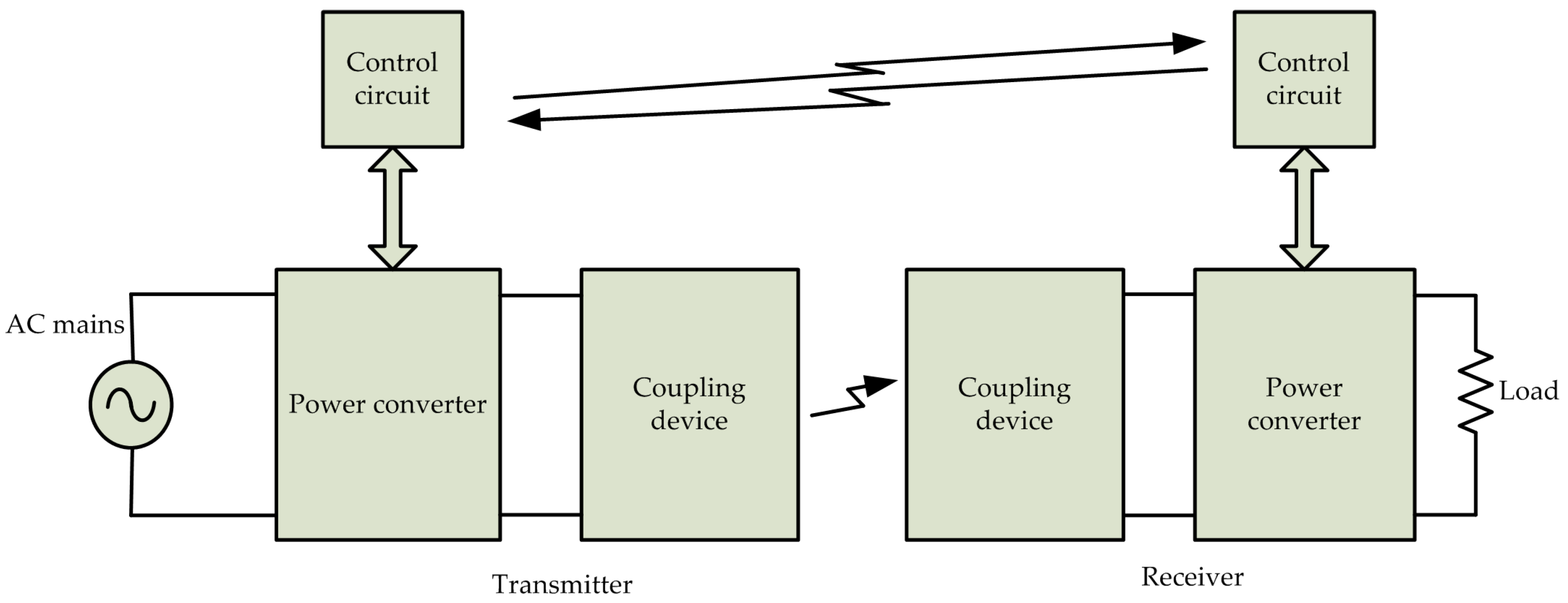
A generic CPT consists of a transmitter supplied with high frequency alternating current (AC), which is generated by a high frequency power converter. The transmitter is coupled with a receiver either through an electric, magnetic or electromagnetic field and induces a voltage in the receiver. The voltage induced at the receiver is fed to the load through a power converter to match the voltage according to the load specifications. The general block diagram of the CPT is given in Figure 1.
Depending on the type of the field involved in transferring energy CPT is differentiated into three different technologies [25] and are: (i) capacitive; (ii) inductive; and (iii) radiant CPTs. A common aspect of the CPT is that the transmitter energizes its surrounding space. The energy stored in inductive and capacitive fields per unit volume of space is:
where µo, εo, B, and E are the permeability and permittivity of free space, magnetic flux density, and electric field intensity, respectively. In practice the maximum energy density in a magnetic field is 104 times greater than that in an electric field, for the maximum values of E, B in free space [25].
2.1. Capacitive CPT
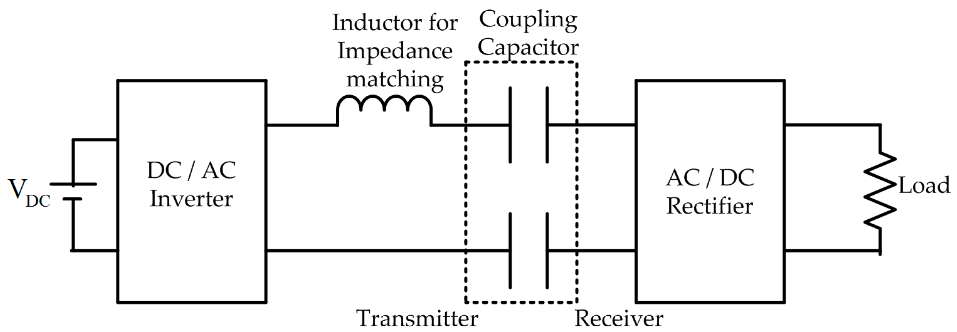
In capacitive CPT the coupling device of the transmitter and receiver consists of metal plates coupled through an electric field [26,27]. The block diagram of capacitive CPT is shown in Figure 2 in which inverter is fed with DC voltage VDC.
The metal plate of the transmitter is excited with a high frequency AC voltage generated by a DC/AC inverter and thereby an electric field is generated between the two metal plates of the transmitter and receiver. Like the working principle of a capacitor, continuity of current is ensured by a displacement current. The induced voltage at the receiver plate is rectified and is provided to the battery load in the case of charging. A series inductor is used to match the input impedance so that power can be transferred efficiently. More power can be transferred by increasing the frequency and capacitance of the coupling capacitors which is inversely proportional to the distance between the coupling plates [26]. The main advantages of capacitive CPT are low losses, negligible electromagnetic emissions and the capability of transferring the electromagnetic field through metal shields without inducing eddy currents. As the energy density stored in free space between the metal plates is comparatively low, it is limited to low power applications.
By overcoming the above limitation Lu et al. transferred 2.4 kW power through capacitive CPT with DC-DC efficiency of 90.8% at an air gap distance between coupling metal plates of 15 cm [28]. They also achieved 90.7% efficiency with 2.1 kW power transfer at 30 cm misalignment and 1.6 kW with 89.1% efficiency at an air gap separation of 30 cm between the metal plates.
Dai and Ludois proposed a conformal transmitter bumper that moulds itself when the vehicle is aligning with transmitter [29]. They achieved high coupling capacitance by minimizing the air gap thereby confining the field between the plates during charging. They achieved approximately 90% efficiency with greater than 1 kW power transfer at an operating frequency of 530 kHz.
Improvements are still required for the overall efficiency, i.e., from the utility supply to the battery load, reduction of voltage stress on coupling metal plates, reduction of current stress in MOSFETs and diodes used in converters.
2.2. Inductive CPT
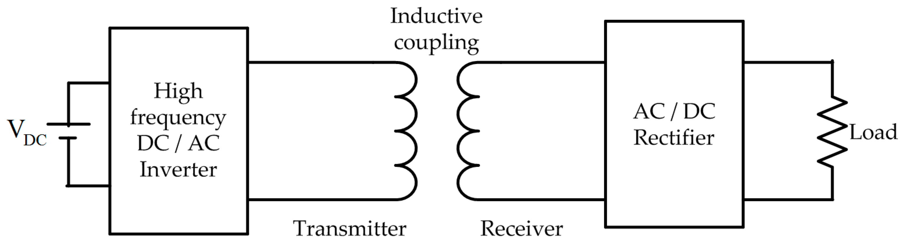
In inductive CPT, the coupling device of the transmitter and receiver consists of a coil coupled through a magnetic field [30]. A block diagram of inductive CPT is shown in Figure 3. In general, the transmitter coil is excited with high frequency AC and generates a magnetic flux in the surrounding space. Voltage is induced in the receiving coil by mutual flux and is provided to the battery load after rectification. As the energy density stored in a magnetic field is high compared to an electric field it can transfer higher power at larger separation between coils. As EV charging needs this feature the remaining sections focus on inductive CPT in detail.
The limitations of inductive CPT include losses associated with the resistance of coils, obstruction of the magnetic field when a metallic body is interposed between them and the production of considerable electromagnetic interference.
2.3. Radiant CPT
Radiant CPT is capable of transferring energy with higher efficiency over distances several times greater than the coupling device size. This is due to execution of directional transmission of electromagnetic (EM) waves. As the size of coupling devices is proportional to the wavelength of the EM waves, high frequency waves such as microwaves and lasers are used to reduce the size of coupling devices. In general, this approach has the disadvantages of being expensive, requiring free line of sight between coupling devices and health hazards [25].
3. Inductive Power Transfer
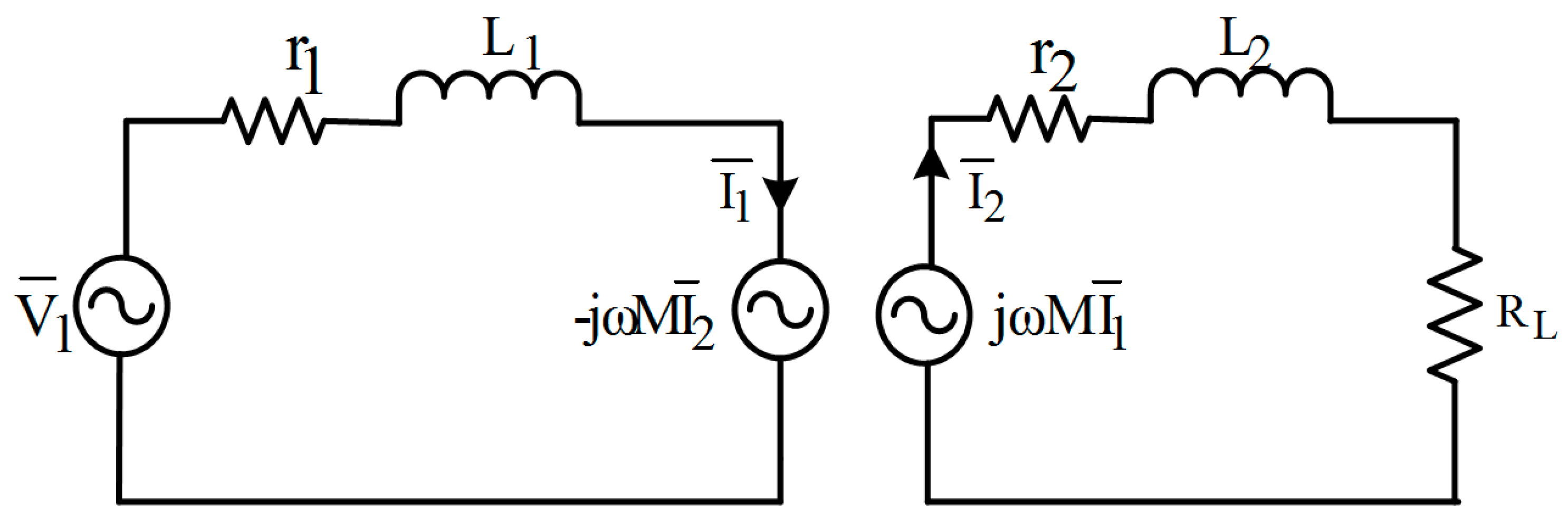
The electrical equivalent circuit of inductive charging is shown in Figure 4 where r1, r2, and L1, L2 are the resistances and inductances of the transmitting and receiving coils, respectively, M is the mutual inductance between two coils, and RL is the equivalent AC load resistance.
Let the transmitting coil is excited with sinusoidal voltage () of angular frequency ω. From the electrical equivalent circuit model, steady state equations at transmitter and receiver side are:
where , are the currents flowing in the transmitting and receiving coils. From Equation (4) the current is given by:
represents the equivalent impedance at the receiving side. Substituting Equation (5) in to Equation (3) gives:
Total impedance () seen from the transmitter side is given by:
From Equation (7) reflected impedance () [31] at transmitter side is given by:
From Equations (4)–(8) it can be observed that the induced and reflected voltage depend on the mutual inductance (M) between the transmitting and receiving coils. M depends on the coupling coefficient (k) given by:
The key performance indexes of the inductive power transfer are efficiency, maximum load power, and sizing power ratio of the voltage source [33]. These are defined as follows:
From Equations (7) and (10) efficiency is given by:
where is the real part of the total impedance as seen from the transmitting end.
Maximum load power (PLmax) can be calculated from the short-circuit power (Ssc) [34] which is the product of the open circuit voltage and short circuit current:
According to the maximum power transfer theorem PLmax is obtained when RL = ωL2 by neglecting the resistance of the coil and is given by:
where PLi,max is maximum load power in uncompensated system. Sizing power ratio (SPR) is defined as the ratio of the nominal apparent power to nominal load power. For the protection of the source SPR should be near to unity. For simplification, we can neglect the resistance and the calculated expression is given by Equation (14):
where SPRi is the sizing power ratio of the voltage source in the uncompensated system. From Equation (11) it can be observed that for maximum efficiency ω and M should be high or resistance should be low.
Need of Compensation in Inductive Power Transfer
It is observed that maximum efficiency is obtained at higher frequency [35] and is given by the condition:
From Equation (7) it can be observed that at high frequency total impedance seen by the source becomes more inductive and the input power factor decreases. This means that for getting high frequency the source side inverter should have a large apparent power rating. Alternatively, to high frequency, it can be observed from Equations (11) and (13) that the maximum efficiency and maximum load power can be obtained by compensation of the receiving coil reactance with a capacitor for a given frequency, mutual inductance, and resistance of both coils. From Equation (14) it can be observed that SPR near to unity can be obtained by compensation of the transmitting and receiving coil reactance with a capacitor.
Depending on the connection of compensation elements either series (S) or parallel (P) at transmitting and receiving side, basic topologies are S-S, S-P, P-S, and P-P [36].
4. Outline of Issues in Inductive Coupled CPT Based on Existing Literature
This section gives a brief description of the significant development of inductively coupled CPT for EV charging from the available literature. This includes major issues, approaches to solve these issues and need to improve these issues for better system performance. For better understanding, a classification of literature is done according to issues and is presented in Table 1. For knowing present status of information related to the gap between transmitter and receiver, efficiency, power transfer, case studies related to applications found in the literature are tabulated in Table 2.
5. Development of Inductive Coupled CPT for EV Charging
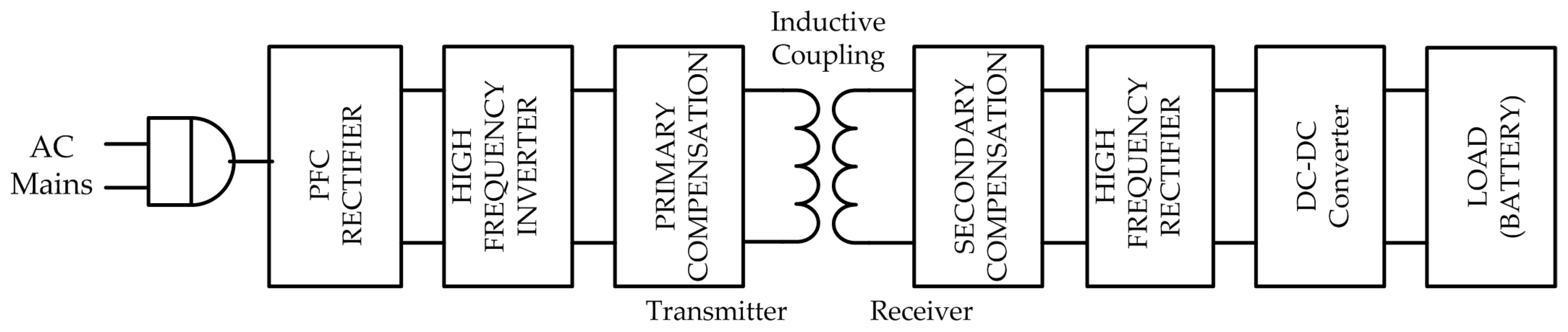
The general block diagram of an inductively coupled CPT is shown in Figure 5. In general, the transmitting coil is paved into the ground and the receiving coil is attached to the chassis of the vehicle. The AC grid supply is converted into DC with a power factor correction (PFC) rectifier.
A diode bridge rectifier along with boost converter can be used as the PFC rectifier. The inductor at the input side of the boost converter helps to maintain the current sinusoidal and in phase with the applied voltage. The sizing of the PFC rectifier for CPT is given in [40] and the main focus of this review is between the DC-DC stage of the transmitter and receiver as the PFC rectifier is mature in design. The DC output of the PFC is converted into high frequency AC by a high frequency inverter and is supplied to the transmitting coil through a compensation network. According to Faraday’s law voltage is induced in the receiving coil and is rectified through the high frequency rectifier for DC loads. A DC-DC converter at the output side is used to match the impedance of the battery.
5.1. Compensation Topologies
5.1.1. Calculation of Compensation Capacitor for the Basic Topologies
From Equation (13) it is observed that for maximum power transfer, is to be compensated with a capacitor and the operating frequency under this condition is termed as the resonant frequency (ω0). For the basic topologies receiver side capacitance at the resonant frequency is given by:
From [31] the reflected impedance (Zro) to the primary at this resonance frequency by neglecting the coil resistance is shown in the last two columns of Table 3. It is observed from Equation (14) that the transmitter side capacitance is to be selected such that it can nullify the equivalent inductance seen from the source and thereby the source volt-ampere (VA) rating is minimized. This zero phase angle frequency should be equal to the secondary resonant frequency to get the maximum power transfer to load and maximum efficiency. The primary capacitance for the basic topologies [20] is shown in the second column of Table 3.
5.1.2. Some of the New Topologies Reported until Now
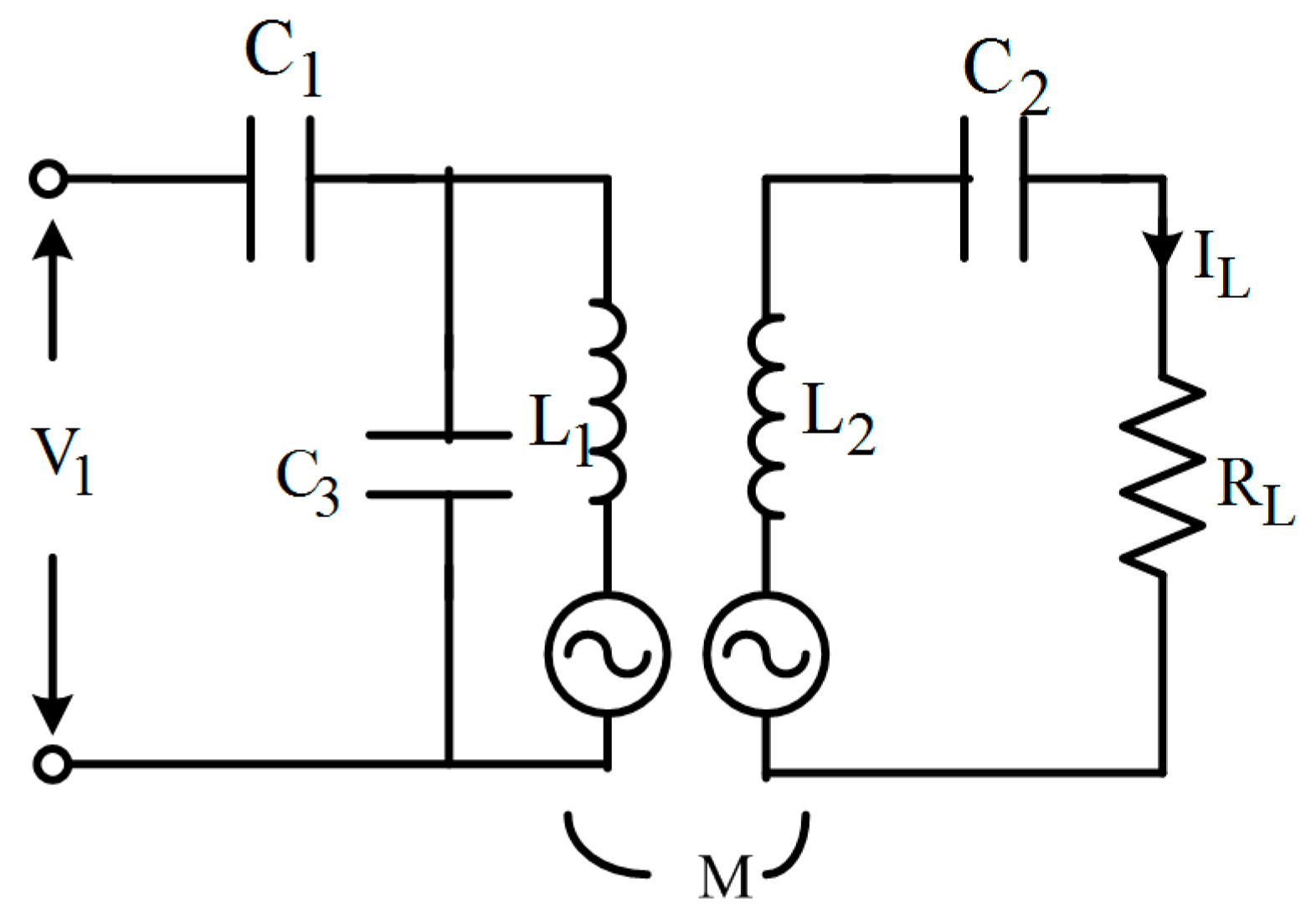
Villa et al. proposed the series parallel series (SPS) compensation topology [38] shown in Figure 6, which is the combination of SS and PS topology. They proposed a selection factor for selection of C3, such that and C3 is given by:
where C3ps is the transmitter side capacitance which is calculated in P-S topology and C1 is to be calculated such that total impedance seen from the input side should be resistive. They showed that at KC = 0.85, 40% misalignment and an air gap of 15 cm, power transferred and supplied by the source are nearly equal to the rated values. They also showed that the source is protected for above 40% misalignment. They compared the SPS topology with the SS topology experimentally for 2 kW power transfer and showed 92% efficiency in the SPS topology, and 89% efficiency in the S-S topology.
C3 = KC·C3ps
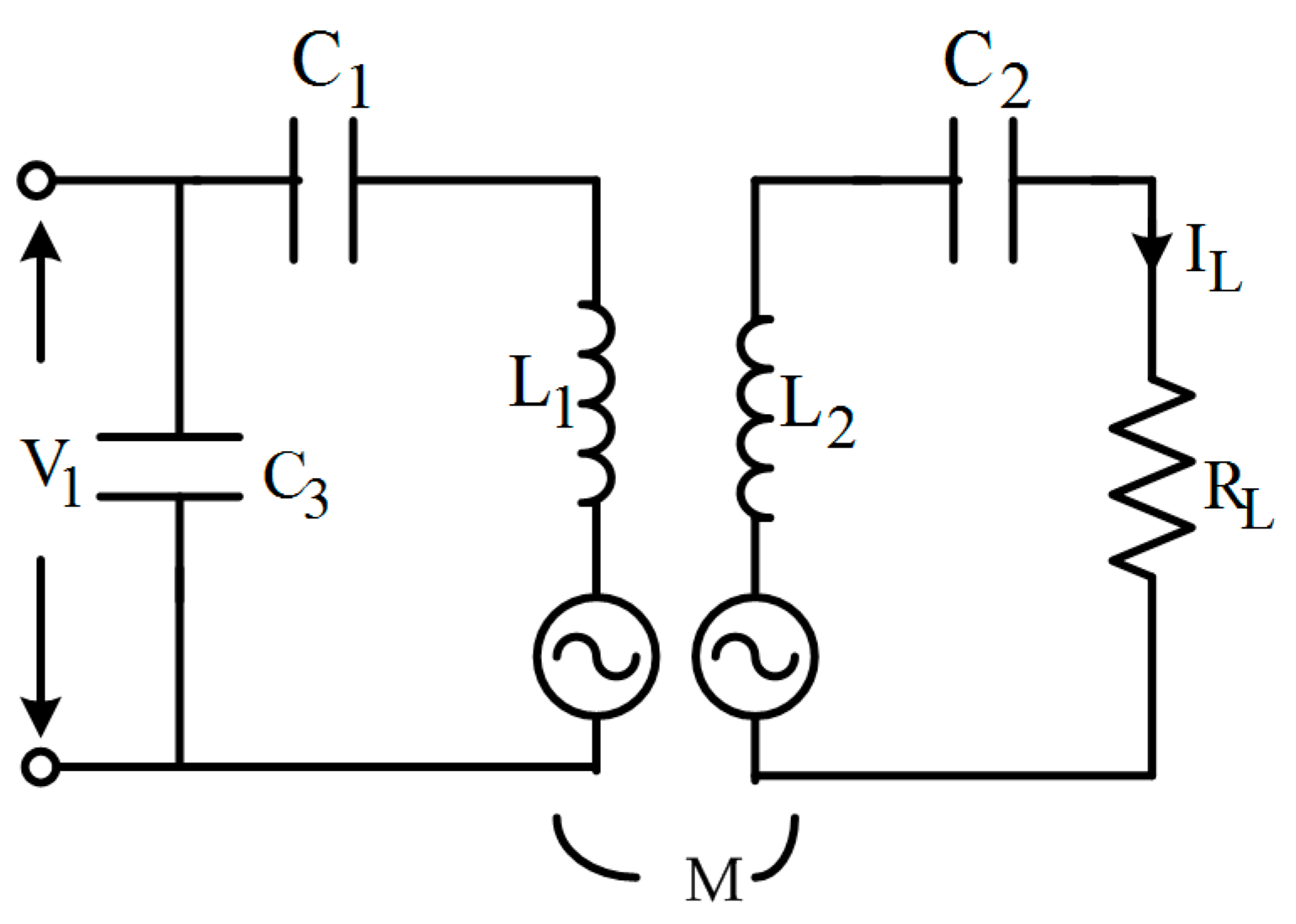
Samanta and Rathore proposed a (C) (LC) type compensation in which capacitor is connected in parallel with series (LC) at the transmitter with current-fed inversion and (LC) type compensation at the receiver side [45] as shown in Figure 7.
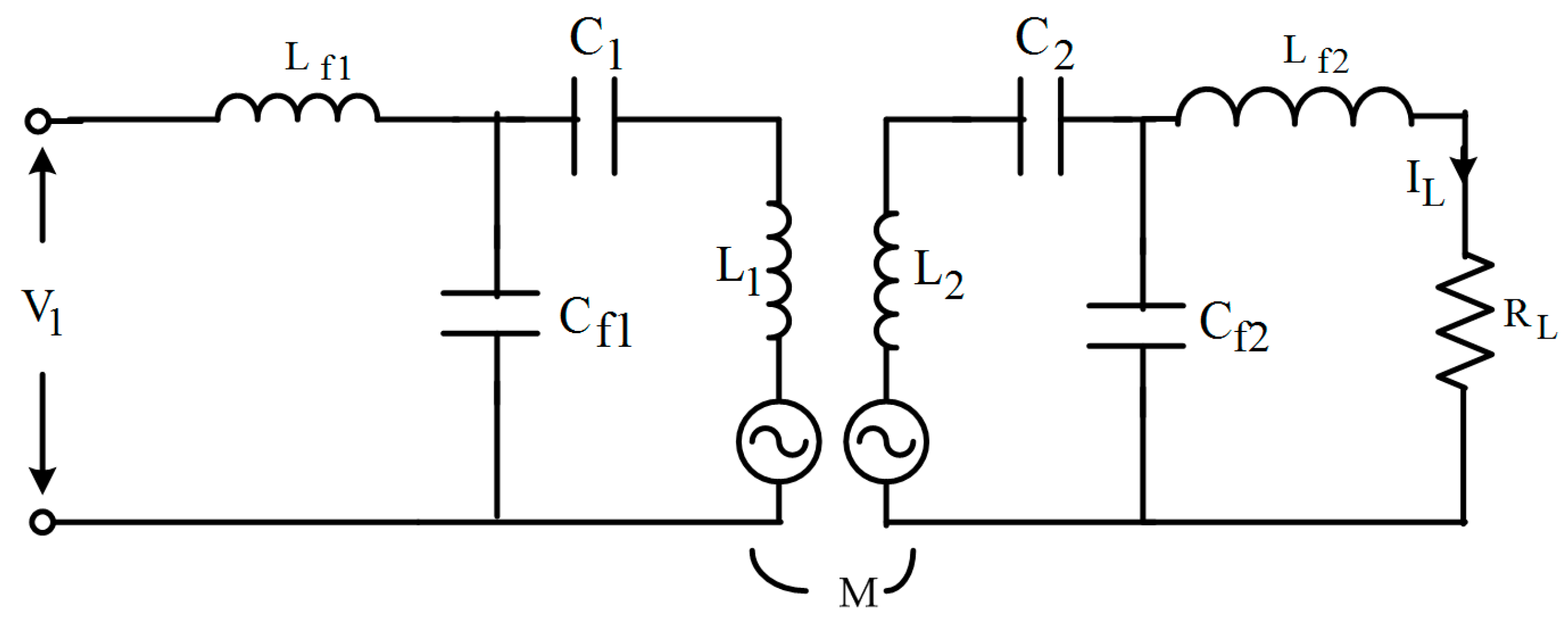
In the PS topology, the entire transmitter coil reactive current is supplied by a parallel capacitor. Due to this voltage, the stress on the parallel capacitor and inverter switches is high. By (C), (LC), and (LC) compensation topology the voltage stress on the inverter switches will reduce and current stress also will reduce as the required reactive power of the transmitting coil is supplied by capacitors. Li et al. proposed an LCC compensation network at the transmitter and receiver sides [46] which is shown in Figure 8.
This compensation is independent of the mutual inductance and load, thereby fixed resonant frequency operation is possible under variable coupling and load conditions. Due to the fixed frequency, the complexity of controlling the inductive CPT is reduced. The authors have demonstrated 7.7 kW inductive CPT with LCC compensation on both sides for an air gap of 20 cm and the achieved efficiency between output power and input DC supply is 96%.
Zhu et al. proposed compensation capacitor optimization for an EV CPT charging system with a four-coil structure [47]. Optimal compensation is achieved by optimization search algorithm with measured coil parameters L, M at the selected frequency. In this case the frequency has to be selected such that the losses in the system will be low. The authors have demonstrated a 3.3 kW CPT prototype with four coil structure. They achieved 92% efficiency at 21 cm air gap and 88.5% efficiency at 36 cm air gap.
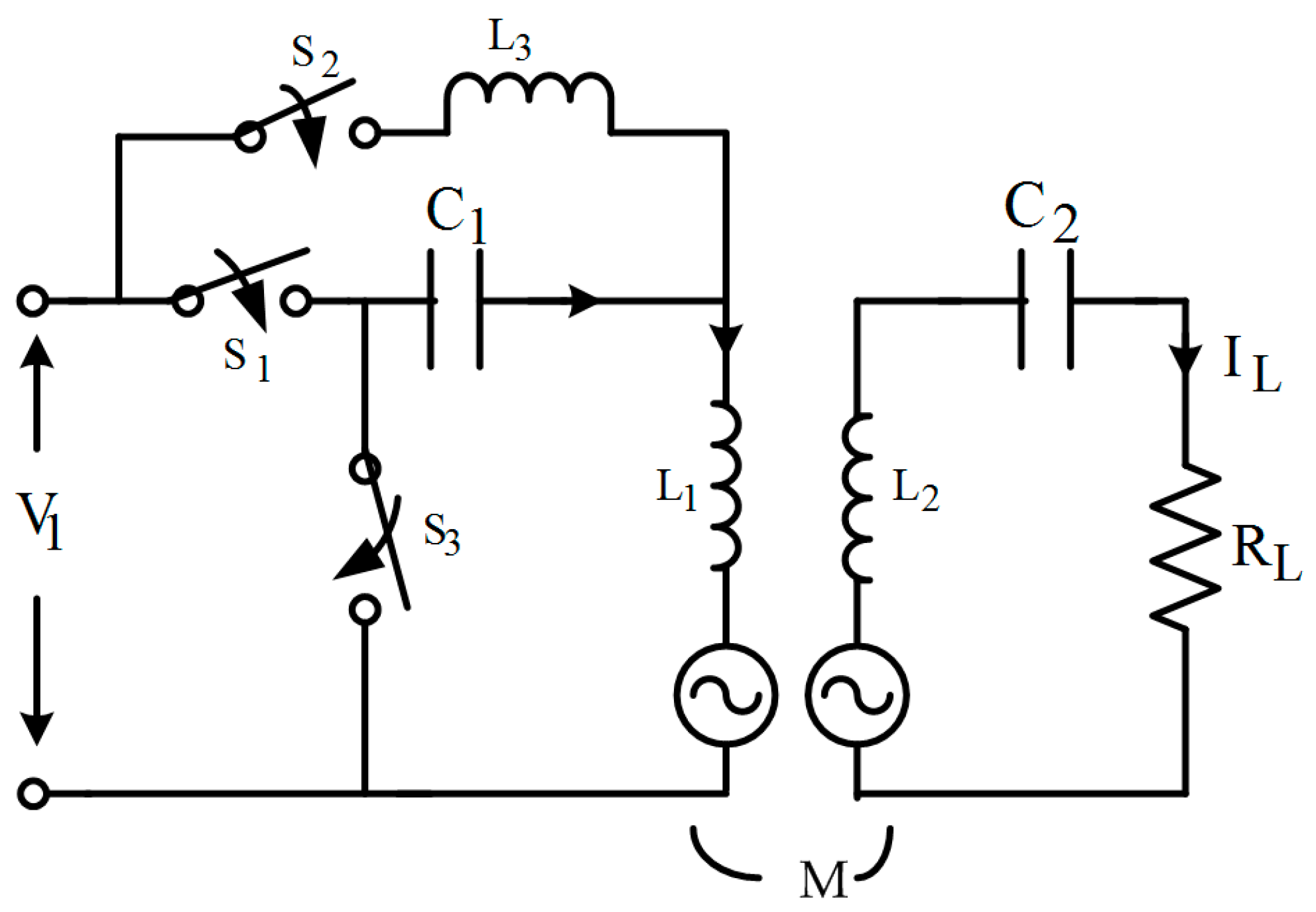
Qu et al. proposed the hybrid topology shown in Figure 9 for load independent constant-current (CC) and constant-voltage (CV) charging profiles for lithium ion batteries which are used in EVs [48]. At resonant frequency, the S-S topology gives load-independent output current and zero phase angle (ZPA) between the input voltage and current [49]. Similarly in [48], conditions in P-S topology for load-independent output voltage and ZPA between input voltage and current are derived.
A combination of S-S and P-S topologies as shown in Figure 9, which results in load-independent CC, CV and ZPA between the input current and voltage, even at fixed frequency. With this topology fixed frequency control technique can be implemented at the input side which is less complex. It acts as S-S topology when S1 is in the ON state, S2, S3 are in the OFF state and acts as P-S topology when S1 is in the OFF state and S2, S3 are in an ON state. Hou proposed a S/S-P compensation topology, which has good output voltage controllability, high efficiency and is less sensitive to misalignment [50].
5.2. Design of the Coil System
For designing the coil the first step is doing the preliminary sizing of the coil based on the chassis to ground clearance (air gap), dimensions of the chassis, space available for placing a coil system and technical requirements of the vehicle [51]. From Equation (18) and Table 3 it is observed that in S-S topology C2, C1 is independent of load resistance and mutual inductance between the coils and there is no imaginary part in the reflected impedance, so this topology is best suited for EVs where the load and coupling coefficient are variable [17]. By considering the advantages of the S-S topology, the approach of coil system design is presented considering this topology. Under resonance conditions Equations (3) and (4) become as follows:
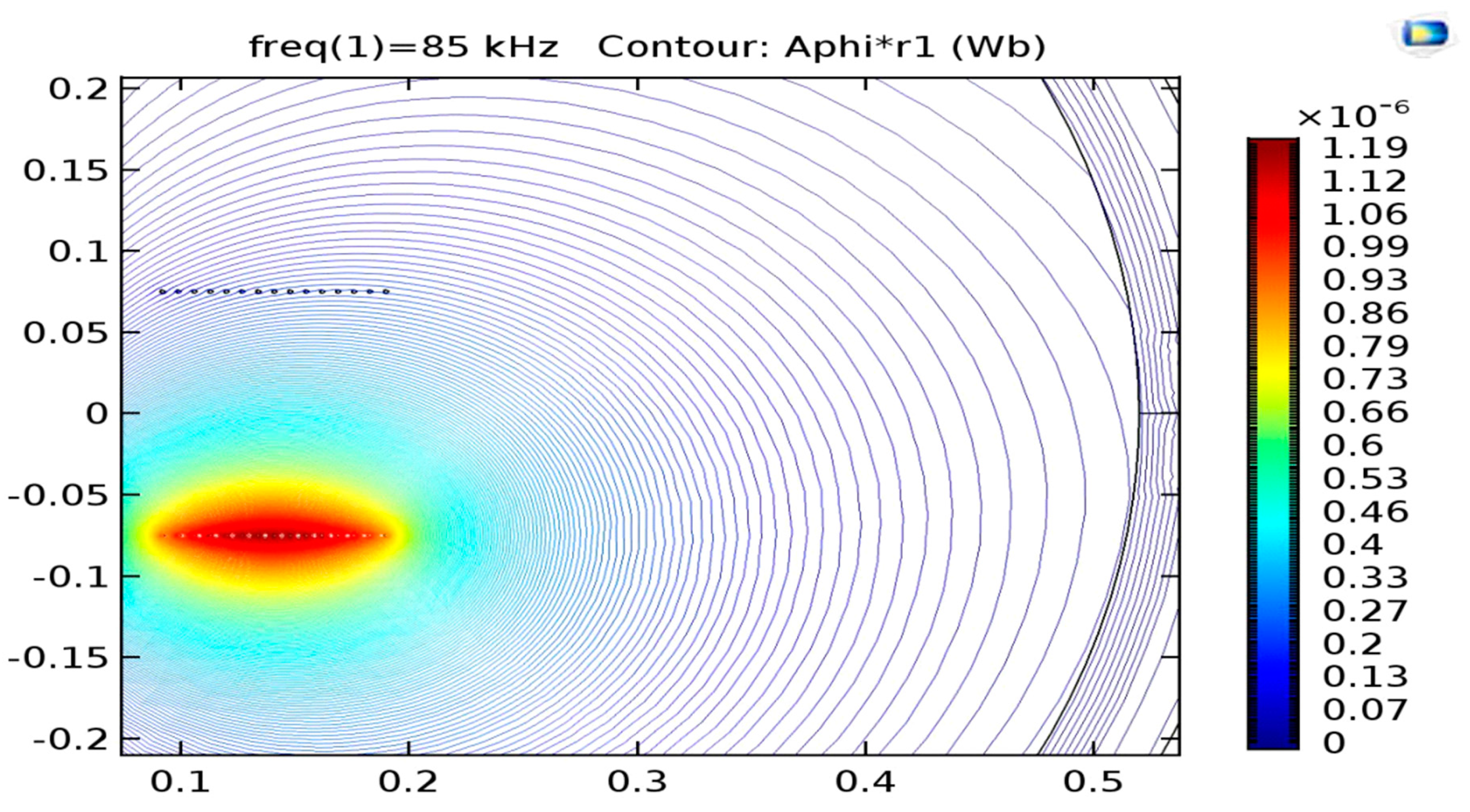
From Equation (18) it is clear that the magnitude of the source voltage must satisfy for the power to transfer from the transmitting side to the receiving side. From the above condition the maximum value of M can be calculated by considering a frequency of 85 kHz as recommended by the Society of Automotive Engineers standard SAE J2954, the peak voltage of the high frequency inverter and the nominal load current. Then, based on the preliminary sizing and shape of the coil, the number of turns can be calculated from the analytical expressions. To reduce the losses due to skin effect, Litz wire is used for the coil. As the analytical expressions are less accurate finite element simulation software is used to get more accurate parameters of the coil that best fit the required load specifications. Simulations are performed across the number of turns found from approximate expressions. To get an optimized geometry a parametric sweep is performed for all parameters of the coil [37,44,51]. Generally circular spiral coils are used in stationary charging due to their high coupling coefficient and equal misalignment tolerance in all directions [52]. The magnetic flux distribution of air core symmetrical spiral coil simulated in 2-D axisymmetric axis of COMSOL finite element analysis (FEA) is shown in Figure 10.
The parameters considered are outer radius of the coil is 0.19 m, 15 turns, turn to turn distance equal to 0.007 m, distance between coils as 0.15 m and excitation current for transmitter coil is 1 A. It can be observed from Figure 10 most of the flux lines are passing above the coil, resulting in lesser k. To guide flux in specific direction ferrite cores of different shapes (I, C, E) are used because they have high magnetic permeability and low electrical conductivity that suppresses magnetic losses at high frequency flux cycles [51].
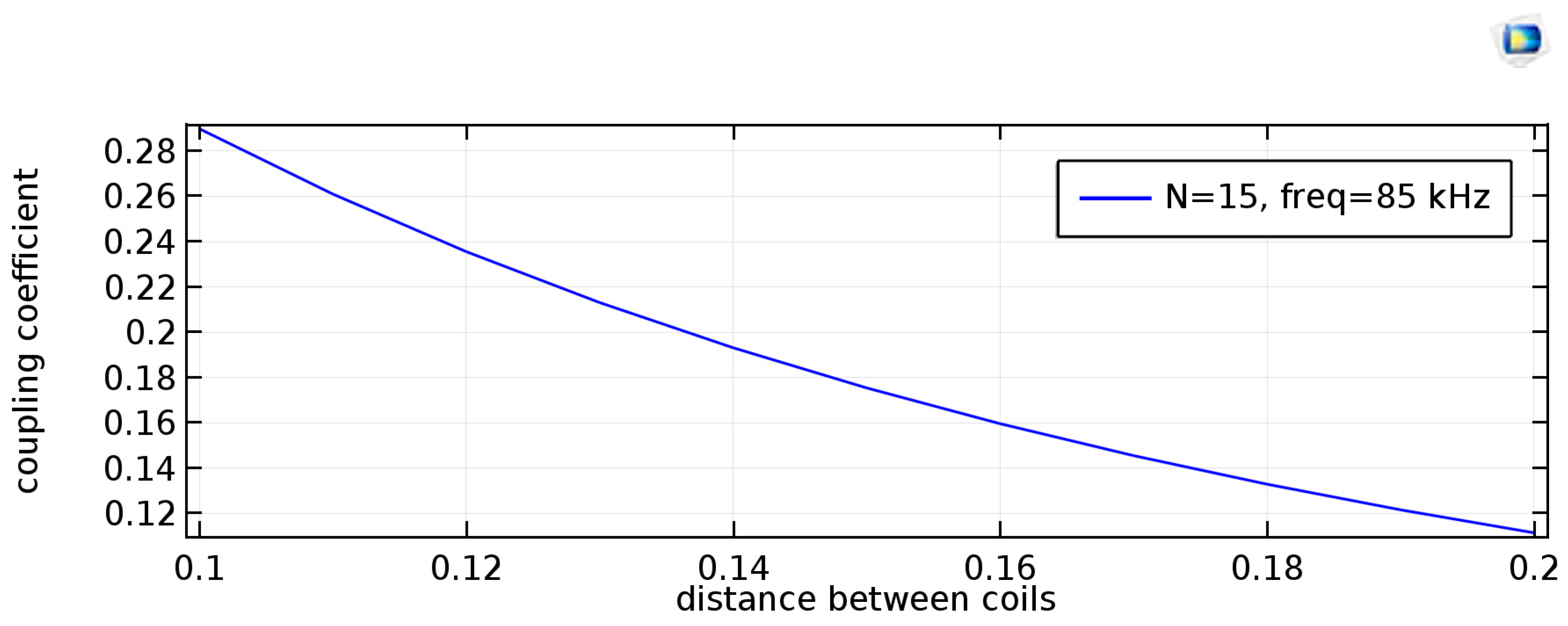
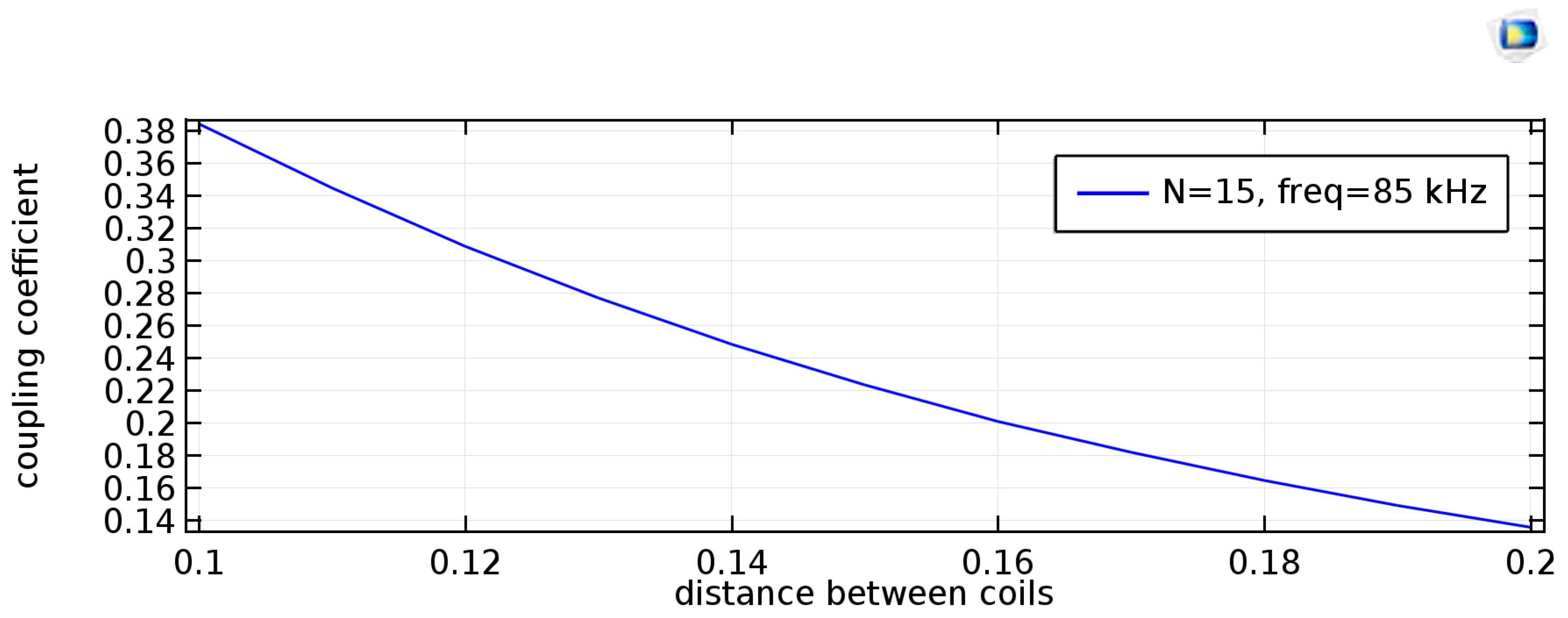
Figure 11 shows the variation of coefficient of coupling for changes in the distance between the coils. One can observe that as the gap between the transmitter and receiver coil increases k decreases. In [51] it can be observed that the self-inductance is independent of the air gap for air core transmitter and receiver coils. It is also reported that as the number of turns increases the self-inductance and mutual inductance increase and as the air gap between two coils increases the mutual inductance decreases. It can also be observed that as turn distance increases, k increases.
Eftekhar et al. reported a study of the efficiency change for gap variation between the two coils [42]. As the distance between coils decreases, i.e., for a small gap between coils, M increases thereby k increases, but the output is more sensitive to misalignment. The third harmonic interference will come into the picture when the gap is less than 4 cm.
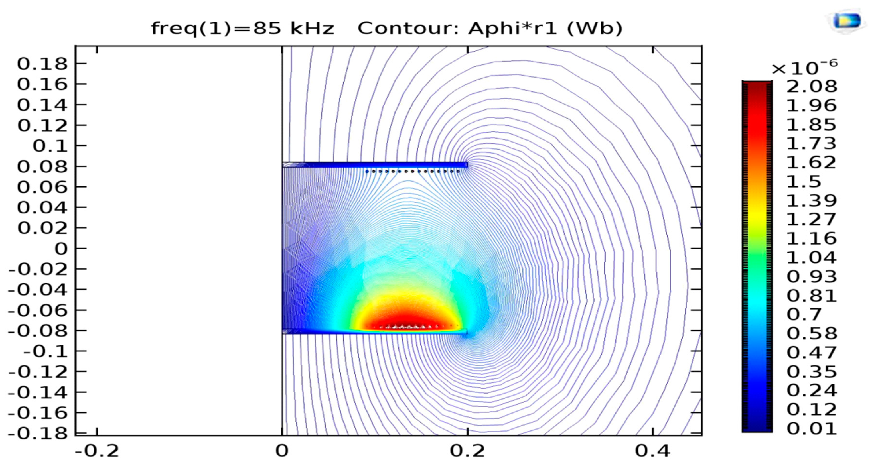
The coefficient of coupling is nearly same for I, C, or E shape ferrite cores, so to decrease the weight of the charger generally I cores are preferred [51]. The magnetic flux distribution of a circular spiral coil with an I core of thickness 5 mm, length 40 cm, relative permeability 3000 and remaining parameters the same as the coreless spiral coil simulated in the 2-D axisymmetric axis of COMSOL FEA is shown in Figure 12.
It can be observed from Figure 12 that most of the flux is guided through the core, thereby k will increase. It can also be observed from the color bar that the magnetic field intensity of flux lines in a spiral coil with a ferrite core is more when compared to an air core spiral coil. Due to the air gap between the coils there is less chance of magnetic saturation in the core, so a thin ferrite core can be used to guide the magnetic flux in specific directions. Reference [37] presented the procedure for optimizing the core with less impact on k by using ferrite bars so that the weight of the coupler is reduced. The limitation of using a core is that the self-inductance changes as the air gap between the coil changes. Figure 13 shows the variation of k for a spiral coil considering an I type ferrite core with gap variation between coils. It can be observed that k increases with the ferrite core and this is the essential feature for CPT of EV charging. As a general observation, in air core spiral coils, k decreases as the air gap between the coil increases.
Tan et al. showed that the inductance of the coil decreases in the presence of metal near the coil thereby reducing the efficiency and maximum power transfer [53]. By increasing the distance between the metal plate and coil, the decrease in inductance will be reduced and the efficiency will increase. For a fixed gap between the metal plate and coil, the decrease in inductance is nullified by placing an optimal number of ferrite bars between the coil and metal plate, so ferrite bars can also be used to improve the efficiency and power transfer capability in the presence of metal near the coil.
Ibrahim et al. designed the resonant inductive CPT with S-S topology considering the chassis of an EV (a RENAULT KANGOO) at the receiver coil [43]. Due to the fact that the chassis is generally steel the receiver side self and mutual inductance of the coils changes. As discussed in [53], the change in coil parameters can be reduced by placing an optimal number of ferrite bars between the chassis and coil.
When there is a misalignment or increase in the gap between the coils, k and the efficiency decrease. This decrease in k and efficiency occurs more in symmetrical coils when compared to asymmetrical coils [39]. Reference [39] reports that k is less sensitive to misalignment and air gap variation when the inner diameter of the transmitter coil is greater than the outer diameter of the receiver coil, but under perfect alignment conditions, k becomes less if the inner diameter of the transmitter coil is far greater than the outer diameter of the receiver coil. It is also reported that for a large inner diameter of the receiver coil, k is more. Based on the analysis the authors developed a 100 W prototype with an inner and outer transmitter coil diameter of 110 mm and 153 mm and inner, outer diameter of the receiver coil of 75 mm, 95 mm. For this case k decreases from 0.3 to 0.216 when the increase in the air gap ranges from 6 mm to 20 mm and k varies from 0.312 to 0.215 for 0 to 50 mm misalignment. The efficiency deviation is within 3.5% for asymmetrical coils.
Quadrature pickups which improve power transfer and are tolerant to lateral misalignments is reported in [54]. Reference [55] presents three generations of online electrical vehicles (OLEVs) in which the second generation which uses an ultra slim U type transmitting coil and the third generation which uses an ultra slim W type transmitting coil are tolerant to lateral misalignments. Optimization of the dimensions of circular coils for high efficiency and tolerance to misalignments is addressed in [56]. Three coil and four coil structures are also less sensitive to gap variation and misalignments [57,58,59].
The efficiency of the coil depends on the losses. For achieving high efficiency, losses should be decreased. Losses are categorized into two types in the coil, namely copper loss and core loss. As a ferrite core has low electrical conductivity, eddy current losses in ferrite cores are smaller. To reduce copper loss generally Litz wires are preferred. Litz wires have to be selected carefully otherwise there can be a greater increase in resistance than with a solid conductor [60]. Reference [61] reports the comparison of losses of coils made with type 2 and type 3 Litz wire. Type 3 has less effective resistance thereby less loss when compared to type 2. In [62] losses in ferrite core, and aluminum plate (which acts as a shield) are simulated and it is found that losses are more in shielding compare to ferrite bars. Reference [62] also showed that when compared to copper losses, losses in the shield is less and give the advantage that the flux density above the receiver, and below the transmitter is much lower.
6. High Frequency Converter and Its Control Strategies
It is observed from the expression (15) that to achieve high efficiency in inductive links the frequency should be higher. To achieve high frequency voltage source inverters (VSI) are used for S-S, S-P compensated topologies [63,64,65,66,67] and current source inverters are used for P-S, P-P compensated topologies [68,69]. As a full bridge VSI gives an output voltage twice than that of a half bridge VSI, a full bridge VSI is suitable for high power applications. As the converters are operating at high switching frequency, silicon carbide MOSFETS with soft switching techniques are used to reduce switching losses [40]. For P-S, P-P compensated topologies, the DC inductor is connected at the input side of the VSI to get a stiff current from voltage source [68,69].
The limitation with S-S compensated topology is that the voltage stress on the capacitors and current stress on the switches is high. This limitation can be overcome in P-S, P-P topologies [68,69] but the transmitter side capacitor depends on k, load.
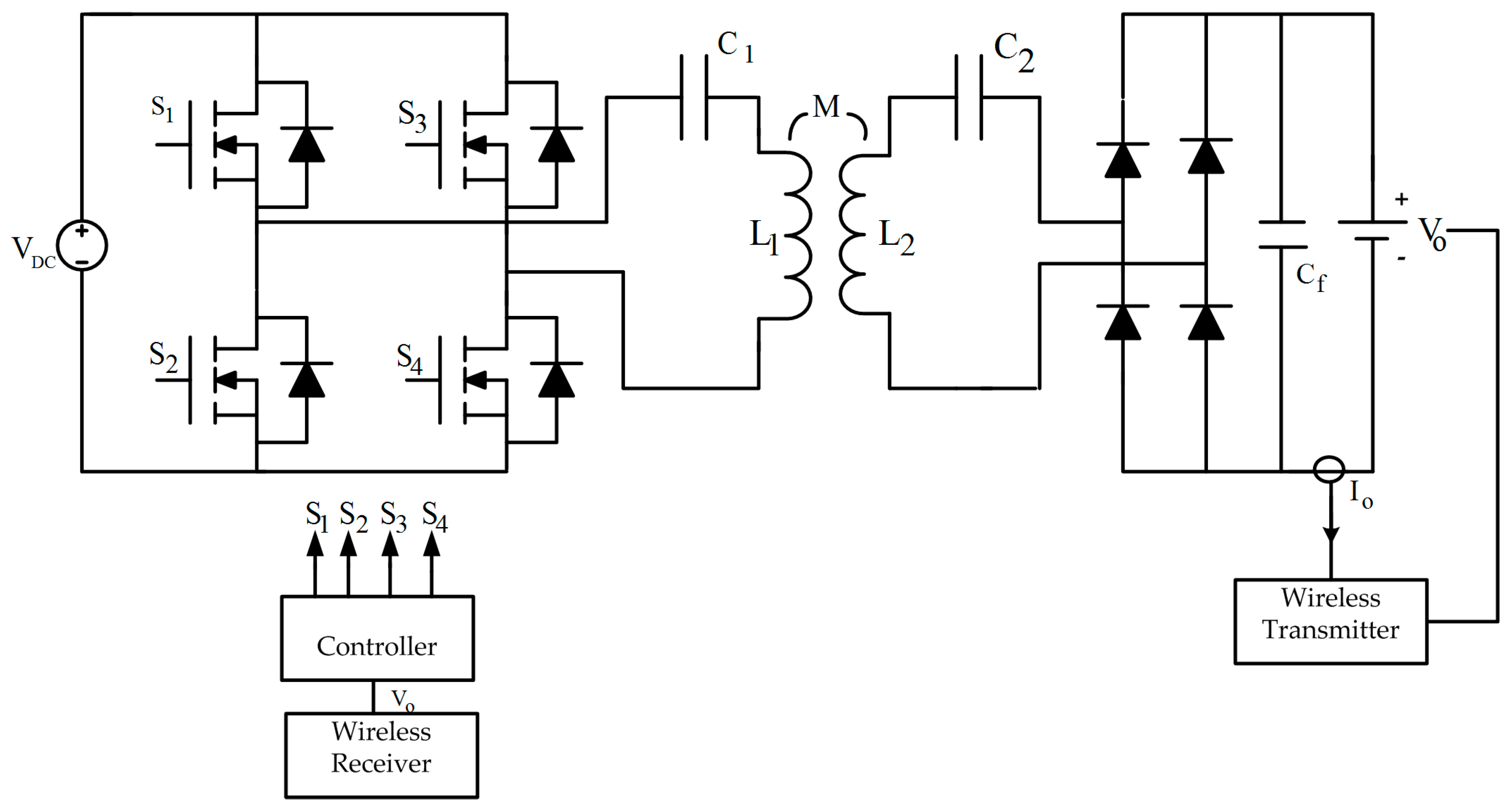
Generally, a phase shift control technique is used to maintain a constant output voltage across the output of a receiver side rectifier and the impedance of the battery is matched by a DC-DC converter at the receiving side with duty cycle control [40]. The schematic of this charging system is shown in Figure 6. The limitation with this type of charging is that the efficiency decreases as the state of charge of the battery increases. References [63,64,65] report a transmitting side control technique which eliminates the receiver side DC-DC converter, thereby the cost and size of the receiver side power electronics are reduced. The closed loop diagram of the inductive CPT charger with S-S compensation, controlled from the transmitting side is shown in Figure 14.
In Figure 14, Vo is the voltage across the battery and Io is the charging current. For any converter dynamic analysis is required to design a controller. References [63,64,65] report dynamic analysis of the converter in CPT scenario based on extended description functions (EDF) as it is simple and accurate. Small signal modeling can be done from the dynamic analysis of the converter and a control loop can be designed based on small signal modeling.
Gao et al. designed a transmitter side controller for uniform voltage gain during misalignments without using communication devices [70]. They designed the controller based on the inverter output voltage and current. They showed the robustness in parking by the frequency modulation of the inverter such that uniform voltage gain is achieved.
Future Recommendations
From Figure 6 it can be observed that the input stage is the conversion of grid supply AC into DC and DC in to high frequency AC. As this is a two-stage process there is scope to implement direct AC-AC conversion to reduce size, cost, losses, and control complexity. One such example for AC-AC conversion is the matrix converter.
From the review, it is observed that research papers showed improvement in performance during misalignment and gap variation, but there is still scope to improve the performance during misalignment and gap variation. Even though asymmetrical coils with greater transmitting coil inner diameter than the receiving coil outer diameter are less sensitive to misalignment, the coefficient of coupling decreases. Study on asymmetrical coils with equal outer diameter in both coils and variation in the inner diameter of the coils is required for a high coefficient of coupling and misalignment tolerance. In practical scenarios shielding is required as the chassis of the vehicle will alter the inductive parameters of the coil. The study of asymmetrical coils with shielding is a useful task as most of the research papers fail to consider the effect of shielding in designing the coils.
As silicon carbide (SiC) MOSFETS have low switching losses, the development of high frequency converters with SiC MOSFETS along with soft switching is beneficial for CPT. Comparative study of efficiency with silicon and SiC MOSFETS is also essential for adopting SiC MOSFETS.
Communication devices are required to transfer the receiving side sensed voltage and current to the transmitting side for controlling the power flow. The study of infrared communication devices and their implementation in CPT is not well addressed in the literature, so there is a gap in implementing communication devices. It is considered a good CPT design if the power is controlled from the transmitting side without using communication devices.
As vehicle to grid and grid to vehicle power transfer are becoming popular, there is a need of development of bidirectional converters with inductive links with respect to topologies and control techniques. Most researchers have focused on improving the performance of the CPT. At the same time, it is important to study the stability of the controllers and converters in the presence of contactless coils and finally loss analysis of the CPT charging system from the input AC supply to the output DC is a useful research topic in developing efficient CPT chargers.
7. Conclusions
An in-depth review of contactless power transfer for EV charging is carried out. Different CPT technologies were discussed; it has been observed that inductive power transfer is suitable for EV charging. From the analytical study of inductive power transfer, it is noticed that compensation is required to cancel the equivalent reactance as seen from the input side of the transmitting side and receiving side coil reactance to improve the efficiency, power transfer capability and to reduce the sizing power ratio. Different types of compensation topologies available in the literature are explained in brief. A generalized comment on the topologies is made highlighting T type structures with partial series compensation to reduce electric stress and to improve performance indexes. The approach to the design of coil is presented with the misalignment study and it has been justified that asymmetrical coils with ferrite cores give better performance during misalignment and airgap variation. Finally, the need of high frequency converters is discussed with the transmitter side control technique and future requirements for EVs have been presented.
Acknowledgments
Authors acknowledge financial support by DST SERB (Government of India), and VNIT Nagpur for the infrastructural support.
Author Contributions
Joint literature survey and paper writing is carried out by both the authors in consent.
Conflicts of Interest
The authors declare no conflict of interest.
Nomenclature
| Wm | Energy density in magnetic field |
| We | Energy density in Electric field |
| B | Magnetic flux density |
| E | Electric field intensity |
| r1 | Resistance of the transmitting coil |
| r2 | Resistance of the receiving coil |
| L1 | Self-inductance of the transmitting coil |
| L2 | Self-inductance of the receiving coil |
| M | Mutual inductance between transmitting and receiving coil |
| RL | Equivalent load resistance on the AC side |
| V1 | Voltage fed to the transmitting coil |
| I1 | Current flowing through transmitting coil |
| I2 | Current flowing through receiving coil |
| Ω | Angular frequency of the voltage fed to the transmitting coil |
| ω0 | Angular frequency at resonance |
| Z2 | Equivalent impedance at receiving side |
| Zt | Total impedance when seen from transmitter side input terminals |
| Zr | Reflected impedance from receiving side to transmitting side |
| Zro | Reflected impedance from receiving side to transmitting side at resonance |
| K | Coefficient of coupling between transmitting and receiving coil |
| PLmax | Maximum load power |
| SSC | Short circuit power |
| SPR | Sizing power ratio for voltage source |
References
- Chau, K.T.; Wong, Y.S.; Chan, C.C. An overview of energy sources for electric vehicles. Energy Convers. Manag. 1999, 40, 1021–1039. [Google Scholar] [CrossRef]
- Chan, C.C. The State of the Art of Electric, Hybrid, and Fuel Cell Vehicles. Proc. IEEE 2007, 95, 704–718. [Google Scholar] [CrossRef]
- Tie, S.F.; Tan, C.W. A review of energy sources and energy management system in electric vehicles. Renew. Sustain. Energy 2013, 20, 82–102. [Google Scholar] [CrossRef]
- Ehsani, M.; Gao, Y.; Miller, J.M. Hybrid electric vehicles: Architectures and motor drives. Proc. IEEE 2007, 95, 719–728. [Google Scholar] [CrossRef]
- Ashique, R.H.; Salam, Z.; Aziz, M.J.; Bhatti, A.R. Integrated photovoltaic-grid DC fast charging system for electric vehicle: A review of the architecture and control. Renew. Sustain. Energy 2016. [Google Scholar] [CrossRef]
- Hannan, M.A.; Hoque, M.M.; Mohamed, A.; Ayob, A. Review of energy storage systems for electric vehicle applications: Issues and challenges. Renew. Sustain. Energy 2017, 69, 771–789. [Google Scholar] [CrossRef]
- Ul-Haq, A.; Cecati, C.; Al-Ammar, A. Modeling of a Photovoltaic-Powered Electric Vehicle Charging station with Vehicle-to-Grid Implementation. Energies 2017, 10, 4. [Google Scholar] [CrossRef]
- Jin, C.; Sheng, X.; Ghosh, P. Optimized Electric Vehicle Charging With Intermittent Renewable Energy Sources. IEEE J. Sel. Top. Signal Process. 2014, 8, 1063–1072. [Google Scholar] [CrossRef]
- Keshri, R.; Bertoluzzo, M.; Buja, G. Integration of a Photovoltaic Panel with an Electric City Car. Electr. Power Compon. Syst. 2014, 42, 481–495. [Google Scholar] [CrossRef]
- Su, W.; Eichi, H.; Zeng, W.; Chow, M.Y. A Survey on the Electrification of Transportation in a Smart Grid Environment. IEEE Trans. Ind. Inform. 2012, 8, 1–10. [Google Scholar] [CrossRef]
- Covic, G.A.; Boys, J.T. Modern Trends in Inductive Power Transfer for Transportation Applications. IEEE J. Emerg. Sel. Top. Power Electron. 2013, 1, 28–41. [Google Scholar] [CrossRef]
- Wu, H.H.; Gilchrist, A.; Sealy, K.; Israelsen, P.; Muhs, J. A review on inductive charging for electric vehicles. In Proceedings of the IEEE International Electric Machines & Drives Conference (IEMDC), Niagara Falls, ON, USA, 2011; pp. 143–147. [Google Scholar]
- Khaligh, A.; Dusmez, S. Comprehensive Topological Analysis of Conductive and Inductive Charging Solutions for Plug-In Electric Vehicles. IEEE Trans. Veh. Technol. 2012, 61, 3475–3489. [Google Scholar] [CrossRef]
- Lukic, S.; Pantic, Z. Cutting the Cord: Static and Dynamic Inductive Wireless Charging of Electric Vehicles. IEEE Electr. Mag. 2013, 1, 57–64. [Google Scholar] [CrossRef]
- Zaheer, A.; Hao, H.; Covic, G.A.; Kacprzak, D. Investigation of Multiple Decoupled Coil Primary Pad Topologies in Lumped IPT Systems for Interoperable Electric Vehicle Charging. IEEE Trans. Power Electron. 2015, 30, 1937–1955. [Google Scholar] [CrossRef]
- Ni, W.; Collings, I.B.; Wang, X.; Liu, R.P.; Kajan, A.; Hedley, M.; Abolhasan, M. Radio Alignment for Inductive Charging of Electric Vehicles. IEEE Trans. Ind. Inform. 2015, 11, 427–440. [Google Scholar] [CrossRef]
- Aditya, K.; Williamson, S. A Review of Optimal Conditions for Achieving Maximum Power Output and Maximum Efficiency for a Series-Series Resonant Inductive Link. IEEE Trans. Transp. Electr. 2016. [Google Scholar] [CrossRef]
- Li, H.L.; Hu, A.P.; Covic, G.A.; ChunSen, T. A new primary power regulation method for contactless power transfer. In Proceedings of the IEEE International Conference on Industrial Technology, Churchill, Australia, 10–13 February 2009; pp. 1–5. [Google Scholar]
- Chao, Y.H.; Shieh, J.J.; Pan, C.T.; Shen, W.C.; Chen, M.P. A Primary-Side Control Strategy for Series-Parallel Loosely Coupled Inductive Power Transfer Systems. In Proceedings of the 2nd IEEE Conference on Industrial Electronics and Applications, Harbin, China, 23–25 May 2007; pp. 2322–2327. [Google Scholar]
- Wang, C.S.; Covic, G.A.; Stielau, O.H. Power transfer capability and bifurcation phenomena of loosely coupled inductive power transfer system. IEEE Trans. Ind. Electron. 2004, 51, 148–157. [Google Scholar] [CrossRef]
- Kim, J.; Kim, J.; Kong, S.; Kim, H.; Suh, I.S.; Suh, N.P.; Cho, D.H.; Kim, J.; Ahn, S. Coil Design and Shielding Methods for a Magnetic Resonant Wireless Power Transfer System. Proc. IEEE 2013, 101, 1332–1342. [Google Scholar] [CrossRef]
- Budhia, M.; Covic, G.A.; Boys, J.T.; Huang, C.Y. Development and evaluation of single sided flux couplers for contactless electric vehicle charging. In Proceedings of the IEEE Energy Conversion Congress and Exposition, Phoenix, AZ, USA, 2011; pp. 614–621. [Google Scholar]
- Mude, K.N.; Dashora, H.K.; Bertoluzzo, M.; Buja, G. From Wired to In-Moving Charging of the Electric Vehicles. In Proceedings of the WSEAS International Conference on Development, Energy, Environment, Economics (DEEE), Lisbon, Portugal, 30 October–1 November 2014; pp. 33–42. [Google Scholar]
- Sallan, J.; Villa, J.L.; Llombart, A.; Sanz, J.F. Optimal design of ICPT systems applied to electric vehicle battery charge. IEEE Trans. Ind. Electron. 2009, 56, 2140–2149. [Google Scholar] [CrossRef]
- Bertoluzzo, M.; Naik, M.K.; Buja, G. Preliminary investigation on contactless energy transfer for electric vehicle battery recharging. In Proceedings of the IEEE 7th International Conference on Industrial and Information Systems (ICIIS), Chennai, India, 2012; pp. 1–6. [Google Scholar]
- Kim, J.; Bien, F. Electric field coupling technique of wireless power transfer for electric vehicles. In Proceedings of the IEEE TENCON Spring Conference, Sydney, Australia, 17–19 April 2013; pp. 267–271. [Google Scholar]
- Theodoridis, M.P. Effective Capacitive Power Transfer. IEEE Trans. Power Electron. 2012, 27, 4906–4913. [Google Scholar] [CrossRef]
- Lu, F.; Zhang, H.; Hofmann, H.; Mi, C. A Double-Sided LCLC-Compensated Capacitive Power Transfer System for Electric Vehicle Charging. IEEE Trans. Power Electron. 2015, 30, 6011–6014. [Google Scholar] [CrossRef]
- Dai, J.; Ludois, D.C. Capacitive Power Transfer through a Conformal Bumper for Electric Vehicle Charging. IEEE J. Emerg. Sel. Top. Power Electron. 2016, 4, 1015–1025. [Google Scholar] [CrossRef]
- Aditya, K.; Williamson, S.S. Design considerations for loosely coupled inductive power transfer (IPT) system for electric vehicle battery charging—A comprehensive review. In Proceedings of the IEEE Transportation Electrification Conference and Expo (ITEC), Dearborn, MI, USA, 15–18 June 2014; pp. 1–6. [Google Scholar]
- Rituraj, G.; Joy, E.R.; Kushwaha, B.K.; Kumar, P. Analysis and comparison of series-series and series-parallel topology of contactless power transfer systems. In Proceedings of the IEEE TENCON Conference, Bangkok, Thailand, 22–25 October 2014; pp. 1–6. [Google Scholar]
- Jiwariyavej, V.; Imura, T.; Hori, Y. Coupling Coefficients Estimation of Wireless Power Transfer System via Magnetic Resonance Coupling Using Information from Either Side of the System. IEEE J. Emerg. Sel. Top. Power Electron. 2015, 3, 191–200. [Google Scholar] [CrossRef]
- Mude, K.N.; Bertoluzzo, M.; Buja, G. Design of a contactless battery charging system. Proceedings of IEEE International Conference of AFRICON, Pointe-Aux-Piments, Mauritius, 9–12 September 2013; pp. 1091–1096. [Google Scholar]
- Stielau, O.H.; Covic, G.A. Design of loosely coupled inductive power transfer systems. Proceedings of International Conference on Power System Technology, Perth, Australia, 23–24 October 2000; pp. 85–90. [Google Scholar]
- Villa, J.L.; Sallan, J.; Llombart, A.; Sanz, J.F. Design of a high frequency Inductively Coupled Power Transfer System for electric vehicle battery charge. Appl. Energy 2009, 86, 355–363. [Google Scholar] [CrossRef]
- Wang, C.S.; Stielau, O.H.; Covic, G.A. Design consideration for a contactless electric vehicle battery charger. IEEE Trans. Ind. Electron. 2005, 52, 1308–1313. [Google Scholar] [CrossRef]
- Budhia, M.; Covic, G.A.; Boys, J.T. Design and Optimization of Circular Magnetic Structures for Lumped Inductive Power Transfer Systems. IEEE Trans. Power Electron. 2011, 26, 3096–3108. [Google Scholar] [CrossRef]
- Villa, J.L.; Sallan, J.; Sanz Osorio, J.F.; Llombart, A. High-Misalignment Tolerant Compensation Topology For ICPT Systems. IEEE Trans. Ind. Electron. 2012, 59, 945–951. [Google Scholar] [CrossRef]
- Zheng, C.; Ma, H.; Lai, J.S.; Zhang, L. Design Considerations to Reduce Gap Variation and Misalignment Effects for the Inductive Power Transfer System. IEEE Trans. Power Electron. 2015, 30, 6108–6119. [Google Scholar] [CrossRef]
- Buja, G.; Bertoluzzo, M.; Mude, K.N. Design and Experimentation of WPT Charger for Electric City Car. IEEE Trans. Ind. Electon. 2015, 62, 7436–7447. [Google Scholar] [CrossRef]
- Miller, J.M.; Onar, O.C.; Chinthavali, M. Primary-Side Power Flow Control of Wireless Power Transfer for Electric Vehicle Charging. IEEE J. Emerg. Sel. Top. Power Electron. 2015, 3, 147–162. [Google Scholar] [CrossRef]
- Eftekhar, M.G.; Ouyang, Z.; Andersen, M.A.E.; Andersen, P.B.; Ribeiro, L.A.; Schaltz, E. Efficiency Study of Vertical Distance Variations in Wireless Power Transfer for E-Mobility. IEEE Trans. Magn. 2016, 52, 1–4. [Google Scholar] [CrossRef]
- Ibrahim, M.; Pichon, L.; Bernard, L.; Razek, A.; Houivet, J.; Cayol, O. Advanced Modeling of a 2-kW Series–Series Resonating Inductive Charger for Real Electric Vehicle. IEEE Trans. Veh. Technol. 2015, 64, 421–430. [Google Scholar] [CrossRef]
- Kim, H.; Song, C.; Kim, D.H.; Jung, D.H.; Kim, I.M.; Kim, Y.I.; Kim, J.; Ahn, S.; Kim, J. Coil Design and Measurements of Automotive Magnetic Resonant Wireless Charging System for High-Efficiency and Low Magnetic Field Leakage. IEEE Trans. Microw. Theory Tech. 2016, 64, 383–400. [Google Scholar] [CrossRef]
- Samanta, S.; Rathore, A.K. A New Current-Fed CLC Transmitter and LC Receiver Topology for Inductive Wireless Power Transfer Application: Analysis, Design, and Experimental Results. IEEE Trans. Transp. Electr. 2015, 10, 357–368. [Google Scholar] [CrossRef]
- Li, S.; Li, W.; Deng, J.; Nguyen, T.D.; Mi, C.C. A Double-Sided LCC Compensation Network and Its Tuning Method for Wireless Power Transfer. IEEE Trans. Veh. Technol. 2015, 64, 2261–2273. [Google Scholar] [CrossRef]
- Zhu, Q.; Wang, L.; Liao, C. Compensate Capacitor Optimization for Kilowatt-Level Magnetically Resonant Wireless Charging System. IEEE Trans. Ind. Electron. 2014, 61, 6758–6768. [Google Scholar] [CrossRef]
- Qu, X.; Han, H.; Wong, S.C.; Tse, C.K.; Chen, W. Hybrid IPT Topologies with Constant Current or Constant Voltage Output for Battery Charging Applications. IEEE Trans. Power Electron. 2015, 30, 6329–6337. [Google Scholar] [CrossRef]
- Zhang, W.; Wong, S.C.; Tse, C.K.; Chen, Q. Load-independent current output of inductive power transfer converters with optimized efficiency. In Proceedings of the 2014 International Power Electronics Conference (IPEC-Hiroshima 2014-ECCE-ASIA), Hiroshima, Japan, 18–21 May 2014; pp. 1425–1429. [Google Scholar]
- Hou, J.; Chen, Q.; Wong, S.C.; Tse, C.K.; Ruan, X. Analysis and Control of Series/Series-Parallel Compensated Resonant Converter for Contactless Power Transfer. IEEE J. Emerg. Sel. Top. Power Electron. 2015, 3, 124–136. [Google Scholar]
- Mude, K.N.; Bertoluzzo, M.; Buja, G.; Pinto, R. Design and experimentation of two-coil coupling for electric city-car WPT charging. J. Electromagn. Waves Appl. 2016, 30, 70–88. [Google Scholar] [CrossRef]
- Aditya, K.; Sood, V.K.; Williamson, S.S. Investigating the magnetic characteristics of unsymmetrical coil pair employing archimedean spiral for EV battery charging. In Proceedings of the IEEE PELS Workshop on Emerging Technologies: Wireless Power Transfer (WoW), Knoxville, TN, USA, 4–6 October 2016; pp. 11–14. [Google Scholar]
- Tan, L.; Li, J.; Chen, C.; Yan, C.; Guo, J.; Huang, X. Analysis and Performance Improvement of WPT Systems in the Environment of Single Non-Ferromagnetic Metal Plates. Energies 2016, 9, 576. [Google Scholar] [CrossRef]
- Elliott, G.A.J.; Raabe, S.; Covic, G.A.; Boys, J.T. Multiphase Pickups for Large Lateral Tolerance Contactless Power-Transfer Systems. IEEE Trans. Ind. Electron. 2010, 57, 1590–1598. [Google Scholar] [CrossRef]
- Lee, S.; Huh, J.; Park, C.; Choi, N.S.; Cho, G.H.; Rim, C.T. On-Line Electric Vehicle using inductive power transfer system. In Proceedings of the IEEE Energy Conversion Congress and Exposition, Atlanta, GA, USA, 12–16 September 2010; pp. 1598–1601. [Google Scholar]
- Hasanzadeh, S.; Vaez-Zadeh, S.; Isfahani, A.H. Optimization of a Contactless Power Transfer System for Electric Vehicles. IEEE Trans. Veh. Technol. 2012, 61, 566–3573. [Google Scholar] [CrossRef]
- Zhang, J.; Yuan, X.; Wang, C.; He, Y. Comparative Analysis of Two-Coil and Three-Coil Structures for Wireless Power Transfer. IEEE Trans. Power Electron. 2017, 32, 341–352. [Google Scholar] [CrossRef]
- Moon, S.; Moon, G.W. Wireless Power Transfer System with an Asymmetric Four-Coil Resonator for Electric Vehicle Battery Chargers. IEEE Trans. Power Electron. 2016, 31, 6844–6854. [Google Scholar]
- Zhu, Q.; Guo, Y.; Wang, L.; Liao, C.; Li, F. Improving the Misalignment Tolerance of Wireless Charging System by Optimizing the Compensate Capacitor. IEEE Trans. Ind. Electron. 2015, 62, 4832–4836. [Google Scholar] [CrossRef]
- Sullivan, C.R.; Zhang, R.Y. Simplified design method for litz wire. In Proceedings of the IEEE Applied Power Electronics Conference and Exposition—APEC 2014, Fort Worth, TX, USA, 16–20 March 2014; pp. 2667–2674. [Google Scholar]
- Wang, S.; Dorrell, D.G. Copper Loss Analysis of EV Charging Coupler. IEEE Trans. Magn. 2015, 51, 1–4. [Google Scholar] [CrossRef]
- Wang, S.; Dorrell, D.G. Loss Analysis of Circular Wireless EV Charging Coupler. IEEE Trans. Magn. 2014, 50, 1–4. [Google Scholar] [CrossRef]
- Zheng, C.; Lai, J.S.; Chen, R.; Faraci, W.E.; Zahid, Z.U.; Gu, B.; Zhang, L.; Lisi, G.; Anderson, D. High-Efficiency Contactless Power Transfer System for Electric Vehicle Battery Charging Application. IEEE J. Emerg. Sel. Top. Power Electron. 2015, 3, 65–74. [Google Scholar] [CrossRef]
- Zahid, Z.U.; Dalala, Z.M.; Zheng, C.; Chen, R.; Faraci, W.E.; Lai, J.S.; Lisi, G.; Anderson, D. Modeling and Control of Series–Series Compensated Inductive Power Transfer System. IEEE J. Emerg. Sel. Top. Power Electron. 2015, 3, 111–123. [Google Scholar] [CrossRef]
- Aditya, K.; Williamson, S. Linearization and Control of Series-Series Compensated Inductive Power Transfer System Based on Extended Describing Function Concept. Energies 2016, 9, 962. [Google Scholar] [CrossRef]
- Esteban, B.; Sid-Ahmed, M.; Kar, N.C. A Comparative Study of Power Supply Architectures in Wireless EV Charging Systems. IEEE Trans. Power Electron. 2015, 30, 6408–6422. [Google Scholar] [CrossRef]
- Wang, Z.; Wei, X.; Dai, H. Design and Control of a 3 kW Wireless Power Transfer System for Electric Vehicles. Energies 2016, 9, 10. [Google Scholar] [CrossRef]
- Samanta, S.; Rathore, A.K. Wireless power transfer technology using full-bridge current-fed topology for medium power applications. IET Power Electron. 2016, 9, 1903–1913. [Google Scholar] [CrossRef]
- Duan, C.; Jiang, C.; Taylor, A.; Bai, K. Design of a zero-voltage-switching large-air-gap wireless charger with low electric stress for electric vehicles. IET Power Electron. 2013, 6, 1742–1750. [Google Scholar] [CrossRef]
- Gao, Y.; Farley, K.B.; Tse, Z.T.H. A Uniform Voltage Gain Control for Alignment Robustness in Wireless EV Charging. Energies 2015, 8, 8355–8370. [Google Scholar] [CrossRef]
Figure 1.
Block diagram of Contactless power transfer (CPT).

Figure 2.
Block diagram of capacitive CPT.

Figure 3.
Block diagram of inductive CPT.

Figure 4.
Equivalent circuit of inductive charging.

Figure 5.
Block diagram of an inductively coupled CPT. PFC: power factor correction.

Figure 6.
Series Parallel Series (SPS) compensation topology.

Figure 7.
(C) (LC) transmitter and (LC) receiver.

Figure 8.
Double-sided LCC compensation.

Figure 9.
Hybrid series-series (SS) and parallel-series (PS) compensation topology.

Figure 10.
Magnetic flux distribution of spiral coil when the transmitter coil is excited with 1 A.

Figure 11.
Coupling coefficient (k) vs. gap distance of spiral coils.

Figure 12.
Magnetic flux lines of a spiral coil with an I core when the transmitter coil is excited with 1 A.
Figure 12.
Magnetic flux lines of a spiral coil with an I core when the transmitter coil is excited with 1 A.

Figure 13.
Coupling coefficient (k) vs. gap distance of a spiral coil with an I type ferrite core.

Figure 14.
Closed loop diagram of inductive CPT with S-S compensation.


Table 1.
Classification of issues according to literature.
| Serial Number | Title of the Paper | Year | Authors | Description | Need of Improvement |
|---|---|---|---|---|---|
| 1 | Optimal Design of ICPT Systems Applied to Electrical Vehicle Battery Charge [24]. | 2009 | Jesus Sallan et al. | Described step by step design of core less Inductively coupled CPT for finding optimal parameters with large air gap that delivers high power efficiently. | Magnetic flux density surrounding the vehicle has to be considered in design process to avoid radiation effect on human beings. |
| 2 | Design and Optimization of Circular Magnetic Structures for Lumped Inductive Power Transfer Systems [37] | 2011 | Mickel Budhia et al. | Describes the design of charging pad that includes Aluminium backing plate, Aluminium ring, Ferrites, coil and plastic cover. Optimization of charging pad with respect to various pad parameters is shown with the aim of high efficiency and power transfer. | Optimization of asymmetrical coils can be evaluated with this procedure as they give better misalignment tolerance. |
| 3 | High Misalignment Tolerant Compensation Topology for ICPT Systems [38] | 2012 | Juan L. Villa et al. | SPS compensation topology is proposed to transfer maximum power in the case of misalignment without having burden on the source. By selecting proper ratio between transmitter side capacitors, combined characteristics of SS and PS topologies are obtained. | Soft switching has to be implemented to reduce switching losses of the converter. |
| 4 | Coil Design and Shielding Methods for a Magnetic Resonant Wireless Power Transfer System [21] | 2013 | Jiseong Kim et al. | Describes passive and active shielding. In passive shielding ferromagnetic materials are used to guide the flux or conductive materials to generate reverse magnetic field. In active shielding counter current source is used to suppress the time varying EMF outside the vehicle. Requirement of current source is eliminated by reactive resonant current loop. | Optimal placement of cancel coils with minimum number of turns is the need of reactive resonant current loop. |
| 5 | Design Considerations to Reduce Gap Variation and Misalignment Effects for the Inductive Power Transfer system [39] | 2015 | Cong Zheng et al. | Coupling coefficient of asymmetrical coils with receiver coil outer diameter less than transmitting coil inner diameter is less sensitive to misalignment and gap variation | Coupling coefficient under perfect alignment condition is less. Asymmetrical coils with equal outer diameter on both coils and variation in inner diameter gives better coupling coefficient and less sensitive to misalignment, gap variation |
| 6 | Design and Experimentation of WPT Charger for Electric City Car [40] | 2015 | Giuseppe Buja et al. | Described step by step design of CPT charger that includes sizing of converters, coil coupling and loss assessment in each stage. | Primary side control technique can be implemented to maintain efficiency of the CPT charger at different stages of battery. |
| 7 | Primary-Side Power Flow Control of Wireless Power Transfer for Electric Vehicle Charging [41] | 2015 | John M. Miller et al. | Power flow to the load is controlled from transmitting side with feedback of receiving side information using wireless communication system | Wireless Communication devices can be eliminated in controlling the power flow from transmitting side. |
| 8 | Efficiency Study of Vertical Distance Variations in Wireless Power Transfer for E-Mobility [42] | 2016 | Morteza Ghorbani Eftekhar et al. | Presented the analysis of effect of decreasing the vertical distance on mutual inductance and efficiency. At low vertical distance mutual inductance is high and efficiency is high but vertical distance less than 4 cm, third harmonic interference will come into picture. | At low vertical distance mutual inductance is more sensitive to horizontal misalignment which should be considered. |
ICPT-Inductively Coupled Power Transfer. In SS, PS, SPS: S stands for series, P stands for parallel. WPT-Wireless power transfer.
Table 2.
Case studies related to applications of CPT.
| Ref No. with Year | Charging Distance | Efficiency | Power Transferred | Operating Frequency |
|---|---|---|---|---|
| Electric city car (2015) [40] | 10 cm | Overall efficiency from grid side AC to battery (DC) is 77% | 560 W | 85 kHz |
| KANGOO RENAULT (2015) [43] | 10 cm | DC-DC efficiency of 89.15% | 2 kW | 33 kHz |
| 1-kW-class golf-cart (2016) [44] | 15.6 cm | DC-DC efficiency of 96% | 1 kW | 20.15 kHz |
Table 3.
Expressions for primary capacitor, reflected resistance and reactance.
| Type of Compensation | Expression for Primary Capacitor for Zero Reactance Seen from Transmitting Side | Reflected Resistance from Receiving Side | Reflected Reactance from Receiving Side |
|---|---|---|---|
| S-S topology | |||
| S-P topology | |||
| P-P topology | |||
| P-S topology |
© 2017 by the authors. Licensee MDPI, Basel, Switzerland. This article is an open access article distributed under the terms and conditions of the Creative Commons Attribution (CC BY) license (http://creativecommons.org/licenses/by/4.0/).
Share and Cite
MDPI and ACS Style
Vaka, R.; Keshri, R.K. Review on Contactless Power Transfer for Electric Vehicle Charging. Energies 2017, 10, 636. https://doi.org/10.3390/en10050636
AMA Style
Vaka R, Keshri RK. Review on Contactless Power Transfer for Electric Vehicle Charging. Energies. 2017; 10(5):636. https://doi.org/10.3390/en10050636
Chicago/Turabian StyleVaka, Ravikiran, and Ritesh Kumar Keshri. 2017. "Review on Contactless Power Transfer for Electric Vehicle Charging" Energies 10, no. 5: 636. https://doi.org/10.3390/en10050636
Note that from the first issue of 2016, this journal uses article numbers instead of page numbers. See further details here.