
Enhanced Microgrid Dynamic Performance Using a Modulated Power Filter Based on Enhanced Bacterial Foraging Optimization

1
Faculty of Engineering, University of Ontario Institute of Technology (UOIT), Oshawa, ON L1H 7K4, Canada
2
Electrical Power & Machine Department, Faculty of Engineering, Zagazig University, Zagazig 44519, Egypt
3
Faculty of Energy Systems and Nuclear Science, University of Ontario Institute of Technology (UOIT), Oshawa, ON L1H 7K4, Canada
*
Author to whom correspondence should be addressed.
Energies 2017, 10(6), 776; https://doi.org/10.3390/en10060776
Submission received: 24 December 2016
/
Revised: 22 May 2017
/
Accepted: 30 May 2017
/
Published: 6 June 2017
(This article belongs to the Special Issue Energy Conservation in Infrastructures 2016)
Abstract
:This paper presents a design of microgrid (MG) with enhanced dynamic performance. Distributed energy resources (DER) are widely used in MGs to match the various load types and profiles. DERs include solar PV cells, wind energy sources, fuel cells, batteries, micro gas-engines and storage elements. MG will include AC/DC circuits, developed power electronics devices, inverters and power electronic controllers. A novel modulated power filters (MPF) device will be applied in MG design. Enhanced bacterial foraging optimization (EBFO) will be proposed to optimize and set the MPF parameters to enhance and tune the MG dynamic response. Recent dynamic control is applied to minimize the harmonic reference content. EBFO will adapt the gains of MPF dynamic control. The present research achieves an enhancement of MG dynamic performance, in addition to ensuring improvements in the power factor, bus voltage profile and power quality. MG operation will be evaluated by the dynamic response to be fine-tuned by MPF based on EBFO. Digital simulations have validated the results to show the effectiveness and efficient improvement by the proposed strategy.
1. Introduction
A microgrid (MG) should have various technical objectives for achieving the criteria of control, stability and reliability for performance. Distributed energy resources (DERs) are important in the operation of MGs; they are wind turbines, solar photovoltaics, micro turbines, fuel cells and others. MGs can manage their own storage, conversion, and recycling of energy. A MG is able to be inherently adapted for DER actions. Thus, MGs should keep away from voltage sag and must achieve balanced active and reactive power profiles. Further, MGs should have additional performance indices for voltage profile and power flow in both islanded operation and connections to utility [1,2,3]. There are many developed devices that are used in MGs to realize enhanced performance with impacted operation. Switching power electronics are installed for controllable actions in MGs. These power electronic devices are applied on both DC and AC systems. Developed flexible AC distribution systems are based on developed switched electronic converters, compensators and drives. Their response emphasizes accuracy with controlled speed to enhance the system dynamics [4,5]. Those developed distribution systems have many control and stabilization devices; one of them is the modulated power filter (MPF), which is remarkable by its simplicity, while it still achieves power quality aspects with harmonic reduction to improve voltage regulation and power factor with a minimization of harmonic levels of voltage and current wave. Conventional controllers regularly have a fixed structure with a constant setting that makes changing the tuned parameters a complex mission especially at different operating cases [6,7]. Dynamic control will be applied to minimize the harmonic reference content and used to be adjusted by controlling the gains for minimizing the global error. That control strategy is highly effective in realizing harmonic reduction, voltage stability and improving power efficiency. The proposed dynamic-error driven controller depends on self-adaptation for dynamic stabilization.
There are different late inquires about the extended levels to depend on advancement heuristic techniques for accomplishing worldwide applications with joining rate. Fuzzy logic programming (FLP) could be associated with this region, but the request of few cycles can build the processing duration of the arrangement. Particle swarm optimization (PSO), additionally, is utilized to manage the improvement issue with execution upgrade. Other advanced methods such as differential evolution (DE), ant colony optimization (ACO), artificial bee colony (ABC) and different methods have significant contributions.
Reference [8] presented a fuzzy logic system (FLS) to plan the adaptive frequency control of an AC MG. This paper addresses the MG framework regarding load changes and proposes a fuzzy gain schedule proportional-integral-derivative (FGSPID) controller, and for relative validation, the conventional PID controller is moreover executed on a similar MG structure. Recreation analysis approves that the frequency control of the MG framework has been upgraded essentially with the utilization of a FGSPID controller when contrasted with the customary controller. Reference [9] presented an upgrade of MG dynamic reactions under severe conditions utilizing the simulated neural system for quick changes of photovoltaic radiation and FLC for wind turbine. It uses an artificial neural network (ANN) to control the outcomes of DGs, by actualizing FLC; it has quicker reactions, smoother control actions, and less disturbance than previously mentioned techniques which prompt enhancement of the dynamic reactions. The models were produced and connected in the Matlab/Simulink program.
Bacterial foraging optimization (BFO) is an advanced technique which is utilized and proposed to be part of framework applications such as in the economic operation schedule, load studies stream and other applications. Enhanced bacterial foraging optimization (EBFO) principally relies upon breeding between PSO with BFO systems. The EBFO strategy assembles powerful PSO with BFO which directs us to the effective seeking method by exceptionally quickened exact joining [9,10,11]. EBFO realizes remarkable impacts, with effective universal property that is independent in solving different numerical optimization problems that lead to positive options of EBFO application and to properly select and control MPF parameters.
In that assigned problem, the search space exploration is performed by EBFO, and exploitation in the explored space is performed that has the objective of getting an enhanced search performance within scheduled media and environments. EBFO is considered and applied for constructive heuristics to generate the arbitrary population and then is used for an improvement heuristic for the population and surface constructed by EBFO. EBFO defines a significant surface to get an optimal pattern. The potential issue of EBFO is that it controls the optimized patterns to be as input factors to the selection cases. EBFO offers a satisfactory state of diversity to all populations, to avoid drawbacks as precocious convergence and others. The hybridization within EBFO has shown potential enhancements over the epoch’s generation; the best individuals are scattered once then after to keep them with the upcoming iteration.
The system response for the operating cases with related MPF parameters will show the effect of getting the significant setting of those parameters to enhance the response [12]. Without adapting the MPF parameters, we may lose the benefits that can be obtained from installing the MPF where that may impair the system response. MPF has been approved for upgrading the execution and power quality parts of the MG with DERs. A novel control regulation for an error-driven dynamic loop by EBFO has been applied to enhance the power quality and energy efficiency criteria. The PWM-optimized pulsing sequence for the MPF utilizes a dynamic loop based on error driven with proportional integral (PI) controller. The proposed MPF is very efficient in the reduction of the harmonic distortion, improving power quality, improving power factor and stabilizing the voltage profile.
2. Microgrid Design and Configuration
The MG design and setup, with all hardware and software facilities, are demonstrated in University of Ontario Institute of Technology by ESCL Lab. The configuration of Microgrid has a lot of distributed generation units such as micro turbine, fuel cell, wind system, and photovoltaic solar units. Different sorts of DC and AC burdens are introduced, for example, resistive burdens, mechanized DC arrangement engine loads, direct AC loads, non linear AC burdens and 3ph. mechanized burdens in form of Induction motor.
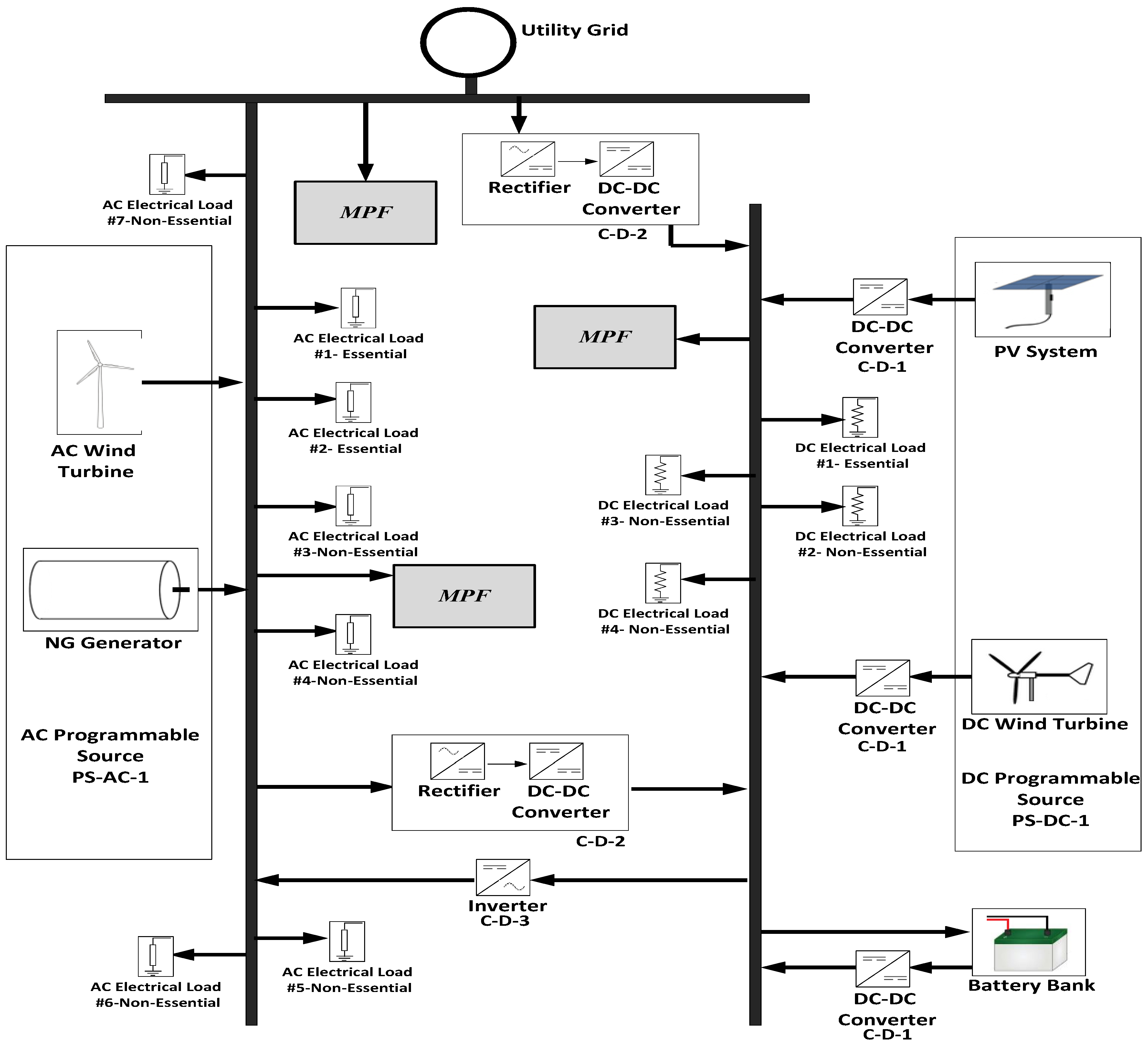
Figure 1 demonstrates MG design, including MPF device for load terminals. This MG has diverse AC/DC DER units that are providing distinctive AC and DC loads. The AC sources are DFIG wind turbine generator and miniaturized scale gas turbine generator. The DC sources are the battery and power module stack in view of hydrogen and PV clusters. For full operation use, there are boosting converters, AC/DC, DC/AC and DC/DC converters associated with the MG [13,14].
MPF Scheme will be chosen according to the location where it will be installed. The global benefits will be to upgrade the voltage profile away from distortions, to lessen the power losses, and to improve the power quality. The details of MG parameters, loading values, DERs and MPFs will be shown later in the following sections.
MPF is considered as one of developed distribution systems. The scheme of MPF is presented in Figure 2, which constructs for the most part with respect to a blend of capacitors, filters associations, transistor switches. The MPF is constructed from three phase capacitors in a series of Rectifier Bridge, and then connected to an inductive element with a resistance and two PWM controlling IGBT switches. The control of IGBT switches is done by complementary S1 and S2 pulses. The equivalent impedance of the device will be varied based on the variation of complementary pulses status. When S1 is OFF (open circuit) and S2 is ON (short circuit), the inductive impedance (R + jX) will make the system connect; when S1 is ON (short circuit) and S2 is OFF (open circuit), the inductive impedance (R + jX) will be out of the system.
The introduced regulated channel plan will be controlled by exchanging the pulsing signals of PWM switch scheme to pick up the ideal control parameters that have dynamical variety to limit the processed dynamic error, which depends on compelling voltage and current, and their harmonics parts. The dynamic controller, in light of loop driven error, depends on the resultant error component which is facilitated to support the control unit of the PWM modified exchanging sections, as appeared in Figure 3. The first loop will be used for stabilizing the voltages that track load voltage deviations in order to maintain the voltage at one PU. The next loop will be used to track the load current dynamic deviations for compensating any occasional changing in the load or the operating condition. The last loop will be used to track the current harmonics to minimize the harmonic component [15,16]. The global computed dynamic error is fed to the PI controller. The resultant signal of the PI controller will supply the PWM, and then the two complementary pulses (S1 and S2) will be generated; that sequence will adapt and control the modulation index.
The optimization technique is applied to tune PI controller parameters (KP and KI) for the MPF devices to get the minimum of the system fitness value. The proposed fitness is characterized by the global errors of all devices:
The signal (): is the resultant error for device MPF 1, : is the resultant error for device MPF 2, and : is the resultant error for device MPF 3. The signal () itself consists of the summation of eV, eI, eP at the location of that device, and so the other and . γi are the weighting for each eV, eI, eP signal.
3. Heuristic Technique Using Enhanced Bacterial Foraging Optimization
Enhanced BFO (EBFO) technique is created on joint of both particle swarm and Bacterial Foraging optimization, to pick up the benefits of them and keep away from the faults of them. PSO relies on its idea of particles that attempt to join with and get away from sticking in a neighborhood; once in a while the normal of the issue prompts trap in that nearby minima. The BFO reproduces the scrounging conduct of microscopic organisms inside the human body [17,18,19,20]. The Normal Choice (NS) controls the microscopic organism’s conduct, as indicated by "the survival for the fittest"; the microorganism that scavenges well is superior to the others, so it survives and the others pass on. The system of BFO relies upon four procedures: chemotaxis, swarming, reproduction and removal–dispersal. There are disadvantages for PSO and BFO; PSO experiences early union before the last settled one, while BFO experiences altering the progression measure in light of uncontrolled molecule speeds, furthermore from the irregular developments of people [21,22,23,24,25]. An improved BFO must deal with the downsides to guarantee a worldwide optimum with a quicker and exact way. The method of EBFO is clarified later in a flowchart, as in Figure 4.
EBFO begins the seeking procedure with microbes starting molecule speed; and that is haphazardly scattered in the arrangement space. Utilizing cell to cell swarming choice, the wellness capacity is resolved to understand the best positions. At that point, there will be a redesign in the individual's positions by a chemotaxis alternative where it utilizes a speed figure. In the reproduction organization, the bacteria which have the most noticeable wellbeing are evacuated, while the others replicate by part into two. At last, removal–dispersal organizing is concerned with evacuating the microscopic organisms, and the best substitutions are instated to accomplish the worldwide optimal position.
Stages for the EBFO procedure will be condensed to execute the technique:
Stage I: Define the assigned controlled variables as taking after:
x: bacteria position, Ft(x): bacteria fitness, N: bacteria number in population, U: optimized variables.
The bacteria (i) has place (x) that relies on some elements: chemotactic (α), reproductive (β), removal–dispersal (γ), and swarm length (λ).
Stage II: Propose arbitrary populations to all individuals to the random initial place x(i), and an arbitrary speed v(i) with random number of −1 : 1.
Stage III: (1). Determine the current fitness Fti current for all bacterium: Fti current = Ft (i, α, β, γ), from the beginning to seeking, where there is little upgrade of bacterium places; therefore, the neighborhood optimum wellness is considered as present amount, Fti local = Fti current.
(2). Decide underlying worldwide wellness of population Ft global = min (Fti local), which owns best optimum location xi best
Stage IV: Begin calculation of cell to cell attractant and repellent formulas of objective trend:
where
- A1
- Attraction quantity percentage
- T1
- Attraction diffusion percentage
- A2
- Repulsion quantity percentage
- T1
- Repulsion diffusion percentage
Stage V: (1). Upgrade objective trend throughout chemotactic formula:
(2). Redesign the speeds and the places in terms of PSO standards:
w, c1 and c2 are inertia, cognitive and social constants; r1 and r2 are random numbers in the interval [−1, 1].
Stage VI: Upgrade the fitness value throughout reproductive formula, later the NC steps of chemotactic, to get the proper bacterium which directs 50% of bacterium to be cancelled; after that all ones have reproduction using the split of two to have the population with the same size:
Stage VII: Upgrade the fitness value again throughout by removal–dispersal actions to reproduce any adjustment of any conditions because of supplement ingestion or critical temperature increment. These terms will achieve removal–dispersal of some bacteria based on later probability Ped of NR cycles of reproductive steps [26,27,28,29,30].
4. Digital Simulations and Discussion
Computerized analyses are performed to present the effectiveness of the proposed strategy to upgrade the power quality and framework stability. They are finished by Matlab/Simulink/SimPower instruments, according to the relegated MG analysis that is depicted as takes after:
- Main Power Network: 140 KV, 5 GVA, X to R = 0
- Micro-Gas System: V = 1.8 kV, P = 220 kW
- Wind Turbine Generator: V = 1.6 kV, P = 1 MW
- Solar PV units: 250 V, 220 kW, Ns = 320, Np = 160, Tx = 295, Sx = 110, Iph = 6, Tc = 25, Sc = 210
- Units of FC: 250 V, 210 KW, Cells = 240 units, Efficiency percentage = 58%
- Batteries/storage: 240 V, operated rate: 320 Ah, discharge Ampere: 20 A
- Combined AC Load_a: linear load: 0.11 MVA, 0.85 lag pf, non linear load: 0.22 MVA, Motor demand (induction): 3 ph., 0.32 MVA, 0.88 pf.
- Combined AC Load_b: linear load: 210 kVA, 0.85 lag pf, non linear load: 210 kVA, Motor demand (induction): 3 ph., 110 kVA, 0.85 pf.
- DC Demand: resistance demand: 110 kW, Motor demand (series): 110 kW
- MPF: Cf = 225 μF, Rf = 0.15 Ω, Lf = 0.1 mH
- Dynamic controller: ɣV = 0.75, ɣI = 0.50, ɣP = 0.65, Rs = 0.11 Ω, Ls = 12 mH
The scope of the paper is focusing on the employment and effect of EBFO on MG operation, main contribution is to compare without and with MPF cases, the conventional PI controller is not adaptive and do not lead to proper operation of MPF. Conventional theory didn’t find the proper settings of MPF due to the stuck in system local minima that is the reason for application heuristic optimization EBFO to the system. Through the EBFO algorithm application, the values of optimized PI Controllers gain for the MPF are presented in Table 1. The proposed optimization technique will be designed to achieve the required performance, based on some values as: population size = 10, chemotactic number = 8, maximum iterations = 120, swim length = 5, inertia constant = 0.9, 0.2, acceleration coeff. = 1.4, 0.15, steps for removal–dispersal = 4, dimension search space = 2–4, probability of removal–dispersal = 0.30, attractant coeff. = 0.01, 0.04, repellent coeff. = 0.01, 10, and No. of reproduction steps = 12.
The MATLAB/SIMULINK/SimPower tools are utilized for MPF modelling and simulation. The digital modelling and analysis is done based on without/with MPF to confirm its performance in voltage stability, and to reduce the harmonic and compensate the reactive power at normal operating conditions. Also, enhancement in the power factor, by managing the exchange power between MG and utility grid, is achieved. The voltage response, current response, reactive power response, power factor, calculated total harmonic distortion percentage (%THDv) for voltage waveforms and total harmonic distortion percentage (%THDi) for current waveforms with cases of with/without MPF are presented [25,26]. The harmonic analysis is shown by calculation of the total THD. The results show that the THD are decreased; also, there is a reduction in the currents THD at the buses. Table 2 shows percentage of total harmonic distortion for voltage waveforms and current elements at different buses and terminals for loads and sources with cases of with and without MPF.
The digital simulations are completed with and without the controlled MPF situated to demonstrate its execution in voltage adjustment, harmonics minimization and reactive power management at typical working conditions. Also, reduction in the enhancement in the power factor managing the exchange power between the MG and utility grid are all achieved and shown in Figure 5, Figure 6, Figure 7, Figure 8, Figure 9 and Figure 10. The dynamic reactions of voltage, current, power related variables (all power components, P, Q, S and pf), %THDv and %THDi at supplied terminals and demanded terminals with examination of harmonics of each terminal with cases of with and without MPF are shown. Harmonics of V and I are examined by THD is shown. Clearly the voltage harmonic levels are fundamentally diminished, likewise harmonic distortion percentage of current waveform at every terminal is diminished.
Referring to the mentioned figures and tables, the controlled MPF mitigates the harmonics and accomplishes other specialized advantages. Differentiating the dynamic response of without and with the proposed MPF, it is totally obvious that the proposed MPF that the proposed MPF upgraded the power quality, enhanced the power factor, managed the reactive power and settled the voltage profile.
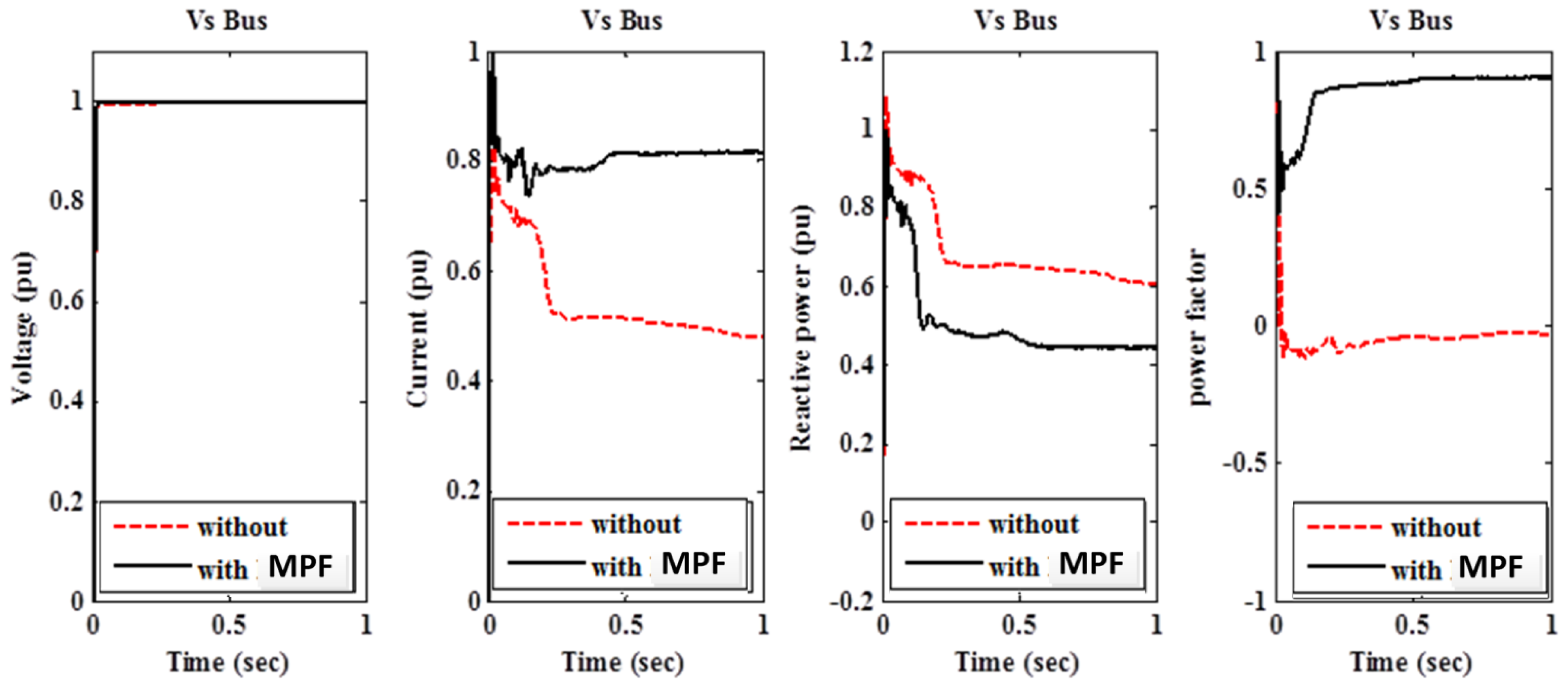
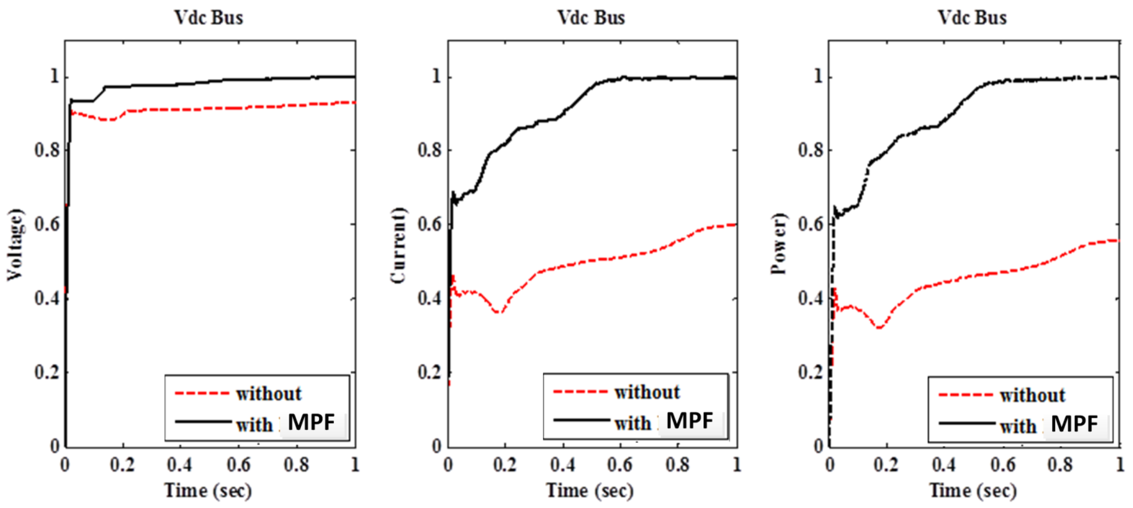
The significant impact on MGs is realized by applying the optimal PID gains that are indicated within Table 1. As indicated by Figure 5, Figure 6, Figure 7, Figure 8, Figure 9 and Figure 10, MPF is able to handle the reactive power of AC/DC buses that lead to stabilization in the voltage profile and improve the power factor. Figure 5 indicates the voltage, current, reactive power and power factor at the power network with Vs. Power factor at this bus is enhanced to 0.91 lag from 0.08 lead; this is because the reactive power is exchanged from MG to the power network. In addition, stabilization of voltage profile with 1 per unit is achieved at bus V1, as indicated in Figure 6. At Vg bus, voltage profile is enhanced for stabilization at 1 pu, as indicated in Figure 8. The values of THD are shown and recorded in Table 2. That table indicated the reduction of THD_voltage and THD_current with MPF that are enhanced and to be kept within limits of the voltage.
5. Conclusions
This paper presented controlled Modulate Power Filters (MPF) that were introduced inside a MG. Adjustment voltage profiles, proficient energy use, upgraded control scheme, and enhanced power quality are vital specialized advantages that could be accomplished. EBFO was connected to powerfully manage the control additions of the tri-loop PI-arrangement that was utilized for the MPF structure to minimize the supreme estimation of the global error signal. Computerized simulations approved the viability of the controlled MPF structure and the control procedure for enhancing power quality and voltage profiles. Improper choice of the control parameters of the PI could influence the dynamic execution, so it was imperative to progressively pick up the optimum patterns. The outcomes demonstrated the viability of the procedure in minimizing all-out supreme error and regard voltage stability, power factor enhancement, and improving of current and voltage dynamics.
Author Contributions
Ahmed M. Othman and Hossam A. Gabbar conceived and designed the proposed technique; Ahmed M. Othman and Hossam A. Gabbar performed the modeling and simulations; Ahmed M. Othman and Hossam A. Gabbar analyzed the data; Ahmed M. Othman and Hossam A. Gabbar contributed analysis tools; Ahmed M. Othman and Hossam A. Gabbar wrote the paper.
Conflicts of Interest
The authors confirm and declare that there is no conflict of interest in the article/research.
Nomenclature
| Ft(x) | Bacteria fitness |
| x | Bacteria position |
| N | Total number of bacteria in the population |
| U | The number of optimized variables |
| A1 | Attraction quantity percentage |
| T1 | Attraction diffusion percentage |
| A2 | Repulsion quantity percentage |
| T2 | Repulsion diffusion percentage |
| r1, r2 | Random numbers in the interval [−1, 1] |
| NC | Steps of chemotactic |
| α | Chemotactic rate |
| β | Reproductive rate |
| γ | Removal–dispersal rate |
| λ | Swarm length |
| v | The speed of a bacterium |
| w | Inertia constant |
| c1 | Cognitive constant |
| c2 | Social constant |
References
- Liu, X.; Wang, P.; Loh, C. A Hybrid AC/DC Microgrid and Its Coordination Control. IEEE Trans. Smart Grid 2011, 2, 278–286. [Google Scholar]
- Fadaee, M.; Radzi, M. Multi-objective optimization of a stand-alone hybrid renewable energy system by using evolutionary algorithms: A review. Renew. Sustain. Energy Rev. 2012, 16, 3364–3369. [Google Scholar] [CrossRef]
- Salas, V.; Olias, E.; Alonsob, M.; Chenlo, F. Overview of the legislation of DC injection in the network for low voltage small grid-connected PV systems in Spain and others. Renew. Sustain. Energy Rev. 2008, 12, 575–583. [Google Scholar] [CrossRef]
- Sajid, G.; Saaed, A.; Siano, P. A comprehensive stochastic energy management system in reconfigurable microgrids. Int. J. Energy Res. Renew. Energy 2016, 90, 430–439. [Google Scholar]
- Fossati, J.P.; Galarza, A.; Martín-Villate, A.; Fontán, L. A method for optimal sizing energy storage systems for microgrids. Renew. Energy 2015, 77, 539–549. [Google Scholar] [CrossRef]
- Sao, C.; Lehn, P. Control and Power Management of Converter Fed Microgrids. IEEE Trans. Power Syst. 2008, 23, 1088–1098. [Google Scholar] [CrossRef]
- Hosseinzadeh, M.; Salmasi, F. Robust Optimal Power Management System for a Hybrid AC/DC Micro-Grid. IEEE Trans. Sustain. Energy 2015, 6, 675–687. [Google Scholar] [CrossRef]
- Kumar, M.; Yadav, A.; Kumar, P.; Pal, N. Fuzzy gain scheduled intelligent frequency control in an AC microgrid. In Proceedings of the 2016 3rd International Conference on Recent Advances in Information Technology (RAIT), Dhanbad, India, 3–5 March 2016. [Google Scholar]
- Rezvani, A.; Branch, S.; Izadbakhsh, M.; Gandomkar, M. Enhancement of microgrid dynamic responses under fault conditions using artificial neural network for fast changes of photovoltaic radiation and FLC for wind turbine. J. Energy Syst. 2015, 6, 551–584. [Google Scholar] [CrossRef]
- Cai, Y.; Wang, J. Differential Evolution with Neighborhood and Direction Information for Numerical Optimization. IEEE Trans. Cybern. 2013, 43, 2202–2215. [Google Scholar] [CrossRef] [PubMed]
- Simon, D. Biogeography-based optimization. IEEE Trans. Comput. 2008, 12, 702–713. [Google Scholar] [CrossRef]
- Neri, F.; Tirronen, V. Recent advances in differential evolution: A survey and experimental analysis. Artif. Intell. Rev. 2010, 33, 61–106. [Google Scholar] [CrossRef]
- Gabbar, H.A.; Othman, A.M. Performance optimisation for novel green plug-energy economizer in micro-grids based on recent heuristic algorithm. IET Gener. Transm. Distrib. 2016, 10, 678–687. [Google Scholar] [CrossRef]
- Othman, A.M.; Gabbar, H.A.; Honarmand, N. Performance Analysis of Grid Connected and Islanded Modes of AC/DC Microgrid for Residential Home Cluster. Intell. Control Autom. 2015, 6, 249–270. [Google Scholar] [CrossRef]
- Mizani, S.; Yazdani, A. Design and operation of a remote microgrid. In Proceedings of the 35th Annual Conference on Industrial Electronics (IECON’09), Porto, Portugal, 3–5 November 2009; pp. 4299–4304. [Google Scholar]
- Rajabi, A.; Fotuhi, M.; Othman, M. Optimal unified power flow controller application to enhance total transfer capability. IET Gener. Transm. Distrib. 2015, 9, 358–368. [Google Scholar] [CrossRef]
- Imthias Ahamed, T.P.; Nagendra Rao, P.S.; Sastry, P.S. A Neural Network Based Automatic Generation Controller Design through Reinforcement Learning. Int. J. Emerg. Electr. Power Syst. 2006, 6. [Google Scholar] [CrossRef]
- Anglani, N.; Muliere, G. Analyzing the impact of renewable energy technologies by means of optimal energy planning. In Proceedings of the 9th International Conference on Environment and Electrical Engineering (EEEIC), Prague, Czech Republic, 16–19 May 2010; pp. 1–5. [Google Scholar]
- Azizipanah-Abarghooee, R. A new hybrid bacterial foraging and simplified swarm optimization algorithm for practical optimal dynamic load dispatch. Electr. Power Energy Syst. 2013, 49, 414–429. [Google Scholar] [CrossRef]
- Patnaik, S.S.; Panda, A.K. Particle swarm optimization and bacterial foraging optimization techniques for optimal current harmonic mitigation by employing active power filter. Appl. Comput. Intell. Soft Comput. 2012, 2012. [Google Scholar] [CrossRef]
- Acharya, D.P.; Panda, G.; Lakshmi, Y.V.S. Effects of finite register length on fast ICA, bacterial foraging optimization based ICA and constrained genetic algorithm based ICA algorithm. J. Digit. Signal Process. 2011, 20, 964–975. [Google Scholar] [CrossRef]
- Liu, X.; Hu, Y.; Feng, J.; Liu, K. A Novel Penalty Approach for Nonlinear Dynamic Optimization Problems with Inequality Path Constraints. IEEE Trans. Autom. Control 2014, 59, 2863–2867. [Google Scholar] [CrossRef]
- Othman, A.M. Optimal capacitor placement by Enhanced Bacterial Foraging Optimization (EBFO) with accurate thermal re-rating of critical cables. Electr. Power Syst. Res. 2016, 140, 671–680. [Google Scholar] [CrossRef]
- Sharaf, A.; Huang, H.; Chang, L. Power quality and nonlinear load voltage stabilization using error-driven switched passive power filter. In Proceedings of the IEEE International Symposium on Industrial Electronics, Athens, Greece, 10–14 July 1995; pp. 616–621. [Google Scholar]
- Anillaga, J.; Bradley, D.; Bodge, P. Power System Harmonics; Wiley: New York, NY, USA, 1985. [Google Scholar]
- Daniel, S. Quality Enhances. In IEEE Spectrum, 2nd ed.; IEEE: Piscataway, NJ, USA, 1996; pp. 34–38. [Google Scholar]
- Bustamante, R.C.; Messina, A.R.; Juarez, C. A New Linear Fractional Transformation Based Approach to Power System Robustness Analysis. Int. J. Emerg. Electr. Power Syst. 2007, 8. [Google Scholar] [CrossRef]
- Munir, S.; Yun, W. Residential Distribution System Harmonic CompensatiAon Using PV Interfacing Inverter. IEEE Trans. Smart Grid 2013, 4, 816–827. [Google Scholar] [CrossRef]
- Djamila, R.; Toufik, R.; Kassa, I.; Abdelmounaim, T. An approach for the modelling of an autonomous induction generator taking into account the saturation effect. Int. J. Emerg. Electr. Power Syst. 2005, 4. [Google Scholar] [CrossRef]
- Liu, J.; Dai, S.; Chen, Q.; Tao, K. Modelling and industrial application of series hybrid active power filter. IET Power Electron. 2013, 6, 1707–1714. [Google Scholar]
Figure 1.
Configuration of microgrid (MG) with modulated power filter (MPF) scheme.

Figure 2.
(a) Simple MPF Representation; and (b) design of MPF.

Figure 3.
Structure of proposed system.

Figure 4.
(a) Flowchart of standard particle swarm optimization (PSO) algorithm [20]. (b) Flowchart of enhanced bacterial foraging optimization (BFO) algorithm
Figure 4.
(a) Flowchart of standard particle swarm optimization (PSO) algorithm [20]. (b) Flowchart of enhanced bacterial foraging optimization (BFO) algorithm

Figure 5.
The measured electrical quantities at Terminal VS.

Figure 6.
The measured electrical quantities at Terminal V1.

Figure 7.
The measured electrical quantities at Terminal VL.

Figure 8.
The measured electrical quantities at Terminal Vg.

Figure 9.
The measured electrical quantities at Terminal Vdc.

Figure 10.
Controlled MPFs errors signals.


Table 1.
Values of optimized proportional integral (PI) controllers’ gains.
| Unit | Optimal Patterns of PI | |
|---|---|---|
| KP | KI | |
| MPF1 | 115 | 15 |
| MPF2 | 150 | 35 |
| MPF3 | 135 | 16 |
Table 2.
Harmonic distortion percentages.
| Case | VS BUS | V1 BUS | VL BUS | Vg BUS | ||||
|---|---|---|---|---|---|---|---|---|
| THD(v) | THD(i) | THD(v) | THD(i) | THD(v) | THD(i) | THD(v) | THD(i) | |
| Without MPF | 0.62 | 7.25 | 35.5 | 21 | 29.3 | 36.8 | 26.7 | 18.5 |
| With MPF | 0.1 | 4.55 | 4.82 | 4.56 | 4.4 | 4.92 | 4.61 | 4.2 |
© 2017 by the authors. Licensee MDPI, Basel, Switzerland. This article is an open access article distributed under the terms and conditions of the Creative Commons Attribution (CC BY) license (http://creativecommons.org/licenses/by/4.0/).
Share and Cite
MDPI and ACS Style
Othman, A.M.; Gabbar, H.A. Enhanced Microgrid Dynamic Performance Using a Modulated Power Filter Based on Enhanced Bacterial Foraging Optimization. Energies 2017, 10, 776. https://doi.org/10.3390/en10060776
AMA Style
Othman AM, Gabbar HA. Enhanced Microgrid Dynamic Performance Using a Modulated Power Filter Based on Enhanced Bacterial Foraging Optimization. Energies. 2017; 10(6):776. https://doi.org/10.3390/en10060776
Chicago/Turabian StyleOthman, Ahmed M., and Hossam A. Gabbar. 2017. "Enhanced Microgrid Dynamic Performance Using a Modulated Power Filter Based on Enhanced Bacterial Foraging Optimization" Energies 10, no. 6: 776. https://doi.org/10.3390/en10060776
Note that from the first issue of 2016, this journal uses article numbers instead of page numbers. See further details here.