A Phase-Shifted Control for Wireless Power Transfer System by Using Dual Excitation Units


1
School of Automation, Chongqing University, 174 Shazheng Street, Shapingba District, Chongqing 400030, China
2
No. 24 Research Institute of CETC, Nanping Huayuan Road No. 14, Nan’an District, Chongqing 400060, China
*
Author to whom correspondence should be addressed.
Energies 2017, 10(7), 1000; https://doi.org/10.3390/en10071000
Submission received: 14 June 2017
/
Revised: 12 July 2017
/
Accepted: 12 July 2017
/
Published: 14 July 2017
(This article belongs to the Special Issue Advanced Electric Devices and Technologies for Electric-Drive Robotics)
Abstract
:Wireless power transfer (WPT) technology can provide intelligent robots with a flexible, robust, and safe power supply, especially in very harsh environments including high humidity and high temperature. To meet increasing power requirement for robotic applications, this paper proposes a novel method to increase system power transfer capability without increasing voltage and current stress, realized by using dual excitation units at the primary side. On this basis, this paper proposes a phase-shifted control method for output power regulation which can keep efficiency high. At the same time, the system is proved to have a better output robust characteristic by analysis under the condition of parameter variation. Finally, experimental results show the proposed dual excitation units (DEU)-WPT system can increase output power by at least three times compared to classical WPT system, and the efficiency is improved by 9%.
1. Introduction
In mobile robot applications, battery charging is seen as a bottleneck problem. Wireless power transfer (WPT) technology can provide a flexible, safe, and convenient way to power the robot [1,2,3,4,5,6]. WPT technology utilizes a magnetic field to transfer energy between two loosely-coupled coils, which can enhance the mobility and reliability of the robots and operate under harsh environments such as humid, high-temperature, dirty, and corrosive environment [7,8,9].
With the rapid development of robotic technology, increasing applications require fast charging. Wireless power transfer capacity should be increased accordingly to meet fast charging requirement. Current research on power capacity improvement can be classified by three groups: the first group of methods utilize composite resonant network to increase system energy absorption ability. The composite resonant network can also provide a system with better anti-frequency drifting ability. LCL (inductor capacitor inductor), CLC (capacitor inductor capacitor) and LCC (inductor capacitor capacitor) composite network are commonly used for the purpose. References [10,11] proposed a WPT system based on an LCL resonant network, which improves the capacity of the resonant tank and accomplishes constant current. References [12,13] used an LCC compensation network in dynamic wireless charging for system optimization. However, the composite resonant network will yield a high system order and slow down system response. Moreover, it may increase the risk of frequency bifurcation due to the existence of more soft switching running points. The second group of methods utilize multi-phase converter and matrix converter to increase high-power conversion ability [14,15], which can reduce the stress of switches at the same time. However, it has a complex circuit structure and the resonant tank still needs to be subjected to excessive current and voltage stress in high-power application. Reference [16] presented a novel dynamic WPT system by combining the multi-parallel system with an LCC composite resonant network, which minimized the electromagnetic interference (EMI) and reduced the system’s power loss. Moreover, for a high-order system (especially parallel multi-inverter), the response of the system is slow and the power regulation is relatively difficult. The third group of methods utilize an additional energy storage and emission circuit to increase the energy storage ability. It is realized by energy injection and emission control to regulate power capacity [17]. In the above methods, in order to achieve high power capacity, high voltage and current stresses will appear in the power conversion and resonant tank system. It will directly increase the cost of whole system and may bring the risk of system failure. Therefore, it is necessary to propose a method to improve system power capacity without increasing voltage or current stress.
In high-power applications of WPT technology, a single excitation unit will meet many difficulties in application, including limited power transfer capacity and high voltage and current stress. The dual excitation units (DEU)-WPT approach with dual excitation units will greatly improve the power transfer capacity and reduce the voltage and current stress at the same time. Furthermore, the output power can be flexibly regulated by controlling the phase-shift angle between dual excitation units. Output characteristics under mutual inductance and load variation are given. Through the specific analysis, the proposed system has a better robust characteristic. Finally, the simulation and experimental results verify the feasibility.
2. Design of DEU-WPT System
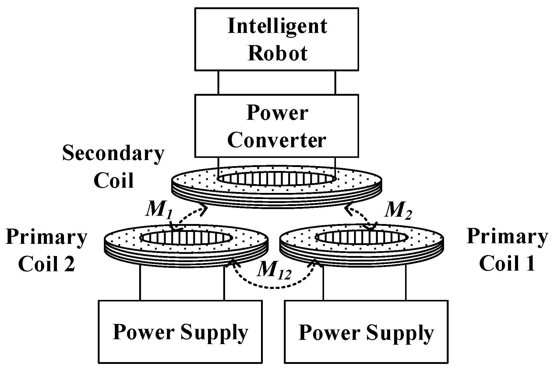
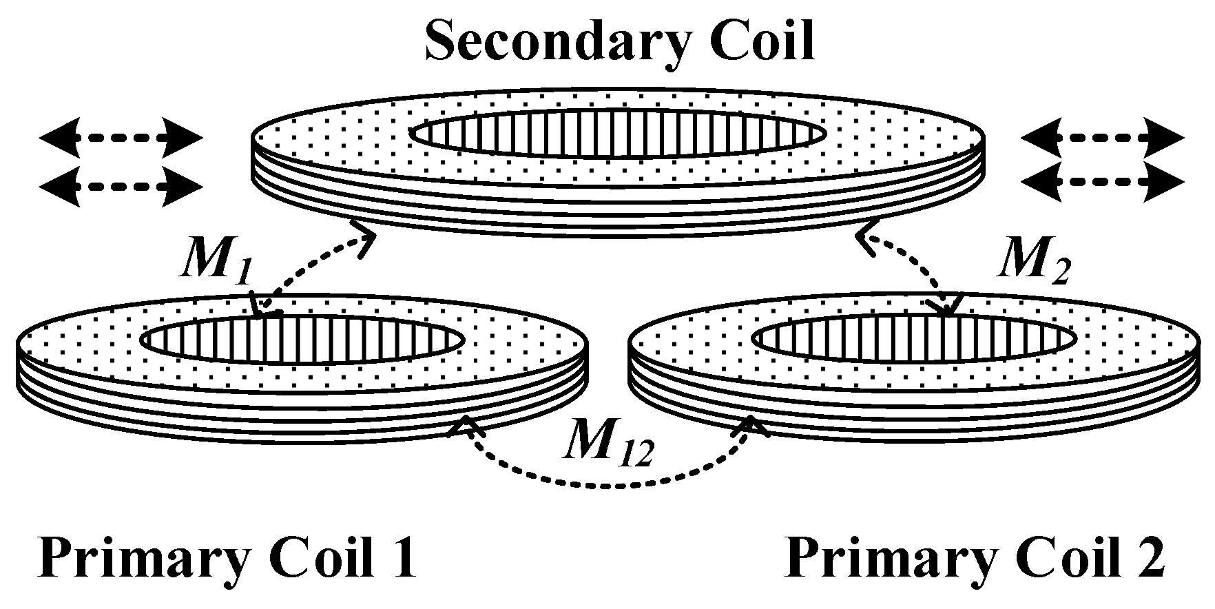
The structure of the system based on the dual excitation unit is shown in Figure 1. Compared with the traditional WPT topology, an excitation unit is added, and each unit is connected by a full bridge inverter circuit. The coil magnetic field is generated and enhanced by the alternating current of the dual track. Considering the parallel compensation of secondary winding will have the phenomenon of frequency drifting, and cross-coupling of primary side coils in DEU-WPT will make the system impedance matching more complicated; in order to reduce the complexity of the system, the series compensation of secondary winding is adopted. Moreover, primary coils which use parallel compensation are the optimal choice when both high transfer efficiency and power output power are required, and specific analysis will be discussed in Section 3 and Section 5. Because the system is a current-mode WPT, it is represented by a large inductance Ldc in series with the DC (Direct Current) power supply. Among them, M1, M2 represent the mutual inductance between each primary coil and secondary coil, and M12 is the cross-coupling inductance. The value of the mutual inductance will have impacts on the output power and efficiency of the system.
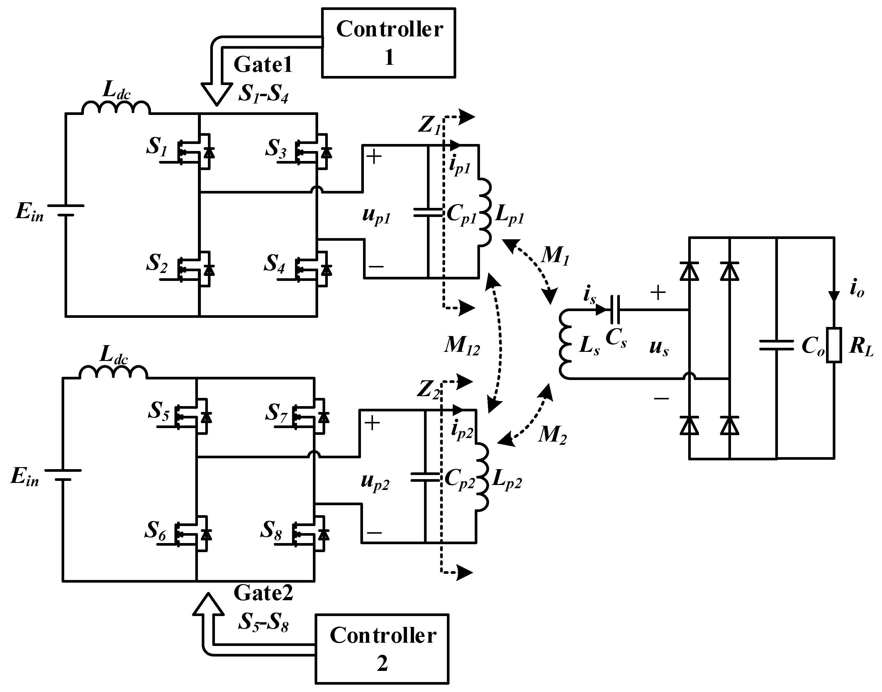
The equivalent circuit of the circuit model is shown in Figure 2, where Lp1, Lp2 are primary coil and Ls are secondary coil inductance, respectively. Cp1, Cp2, and Cs are the resonant capacitance. ip1, ip2 are resonant currents in the coil. up1 and up2 are resonant voltage at the primary side. Z1 and Z2 are the reflection impedance. Co is the capacitance of rectifier circuit, and RL is the equivalent load resistance.
According to the KVL’s (Kirchhoff Laws) law, the phasor equation of voltage and current in the DEU-WPT system can be derived as
where . In order to obtain balanced excitation, assume that Lp = Lp1 = Lp2. The process variables are defined as follows
The primary current equation can be derived by
According to (1) and (3), the impedance of the primary coil branch can be deduced as
As can be seen in (3) and (4), the impedance of the primary coil branch changes with equivalent load variation when M1, M2, and M12 changes under the condition of charging. When the value of M1 and M2 is closed, the order of magnitude of is small, which is almost equal to 0. Equation (4) can be derived as
In other words, the coil resistance and reflection impedance will dominate the real part of Z1 and Z2, which depends on mutual inductance. Similarly, the imaginary part of Z1 and Z2 is decided by M12 and Lp. The resonant frequency of the secondary resonant tank can be designed as
The compensation capacitance of primary side of DEU-WPT can be obtained
3. Comparison Analysis between WPT and DEU-WPT System
It is necessary that a comparison analysis between a classical WPT system and a DEU-WPT system should be considered. To analyze the characteristics of the system more intuitively, assume that M1 = M2 = M for simplicity, and the impedance of the primary coil branch can be expressed as
From (8), the real part of and are reflection impedance, which are twice than the reflecting impedance of traditional WPT system. When , and the parameters of dual excitation units are same (that is, ), the resonant current on the coil can be derived as
The output power can be deduced as
Considering the loss of resistance and , the loss of the primary resonant network for and secondary loss of is as follows
The expression for the efficiency can be obtained
where is much greater than ; this formula can be simplified for
In order to analyze the output characteristics of DEU-WPT system, Table 1 gives a comparison of PS (Primary Parallel Secondary Series) DEU-WPT systems as well as traditional PS-type WPT systems in the case of the same parameter matching. Where the is the mutual inductance of WPT, is the mutual inductance of DEU-WPT and the is the cross-coupling inductance of DEU-WPT. is the reflection impedance of the system. and are the impedance angle of the primary resonant network, which equals to the imaginary part divided by the real part of an impedance.
Table 1 shows that the reflection impedance Zrs of DEU-WPT is two times that of classical WPT. Furthermore, the efficiency η of the DEU-WPT system has obviously been improved because the ratio of numerator to the denominator of η increases. In practice, the resonant network cannot be matched ideally, and the coupling coefficient of cross-mutual inductance is generally less than 0.05, so because of reflection impedance Zrs (real part of impedance) of DEU-WPT is much greater while the imaginary part of DEU-WPT () is almost equal to the imaginary part of WPT (); that is to say, the of DEU-WPT is reduced. Similarly, compared with classical WPT system, the of DEU-WPT is reduced to a certain extent due to the increase of reflected impedance and the existence of cross-mutual inductance.
However, to verify the PS topology, the DEU-WPT system has improved the output power compared with the traditional PS topology WPT, only needing to guarantee
where represents the output power of DEU-WPT and represents the output power of WPT. To prove (14), assume that and bring in the expressions of resonant current in Table 1, as follows
Simplified as
From (16), when , the inequality is equal. However, the loose coupling coefficient k is generally equal to or less than 0.3, so obviously. It can be concluded that, in theory, the output power of the PS topology DEU-WPT can increase the output power by four times compared with the PS topology WPT when Lp >> M12.
Generally, it is justified that the DEU-WPT system reduced the stress of voltage and current in resonant tank compared to a classical WPT system, and cross-coupling M1 and M2 will have a direct influence on impedance matching. Additionally, the cross-coupling M12 between dual primary units will influence the power gain, which can be seen in Equation (16). The optimum output characteristic of system will be analyzed specifically in Section 5 when the mutual inductance is asymmetric.
4. Control Method of Output Power
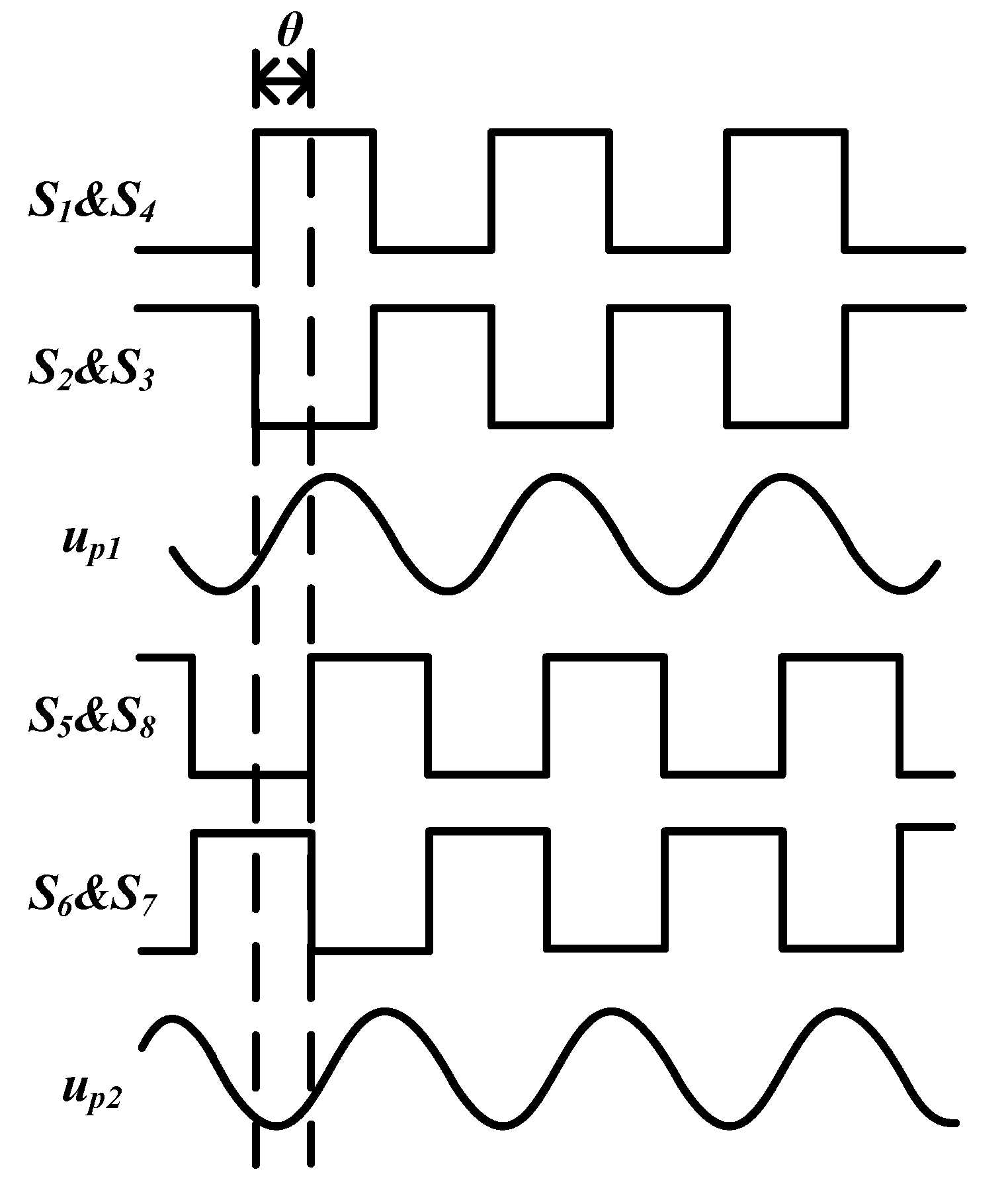
For the DEU-WPT system, the phase difference θ between resonant current and will directly influence the magnetic field intensity. This paper proposed an output power regulation method to control and so that phase difference θ between and could be regulated. Figure 3 gives the phase-shifted waveform. The resonant voltage phasor is controlled by phase-shift of the driving signal, as shown in Figure 3; S1–S4 is the driving signal in inverter 1, and S5–S8 is the driving signal in inverter 2.
According to (1), the and be expressed as
where , and the RMS (Root Mean Square) of on the secondary side can be derived as
Because and , set the phase offset between and as
Output power can be obtained
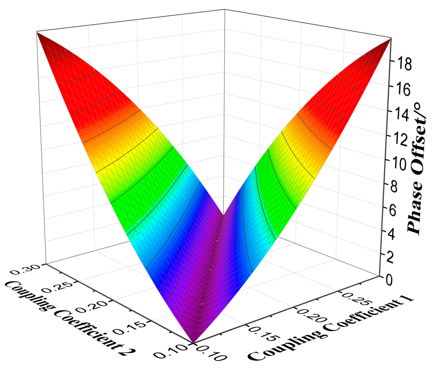
According to (19), phase offset is dependent on different coupling coefficients. Figure 4 shows the phase offset variation with respect to coupling coefficients k1 and k2, where k1 and k2 are from 0.1 to 0.3.
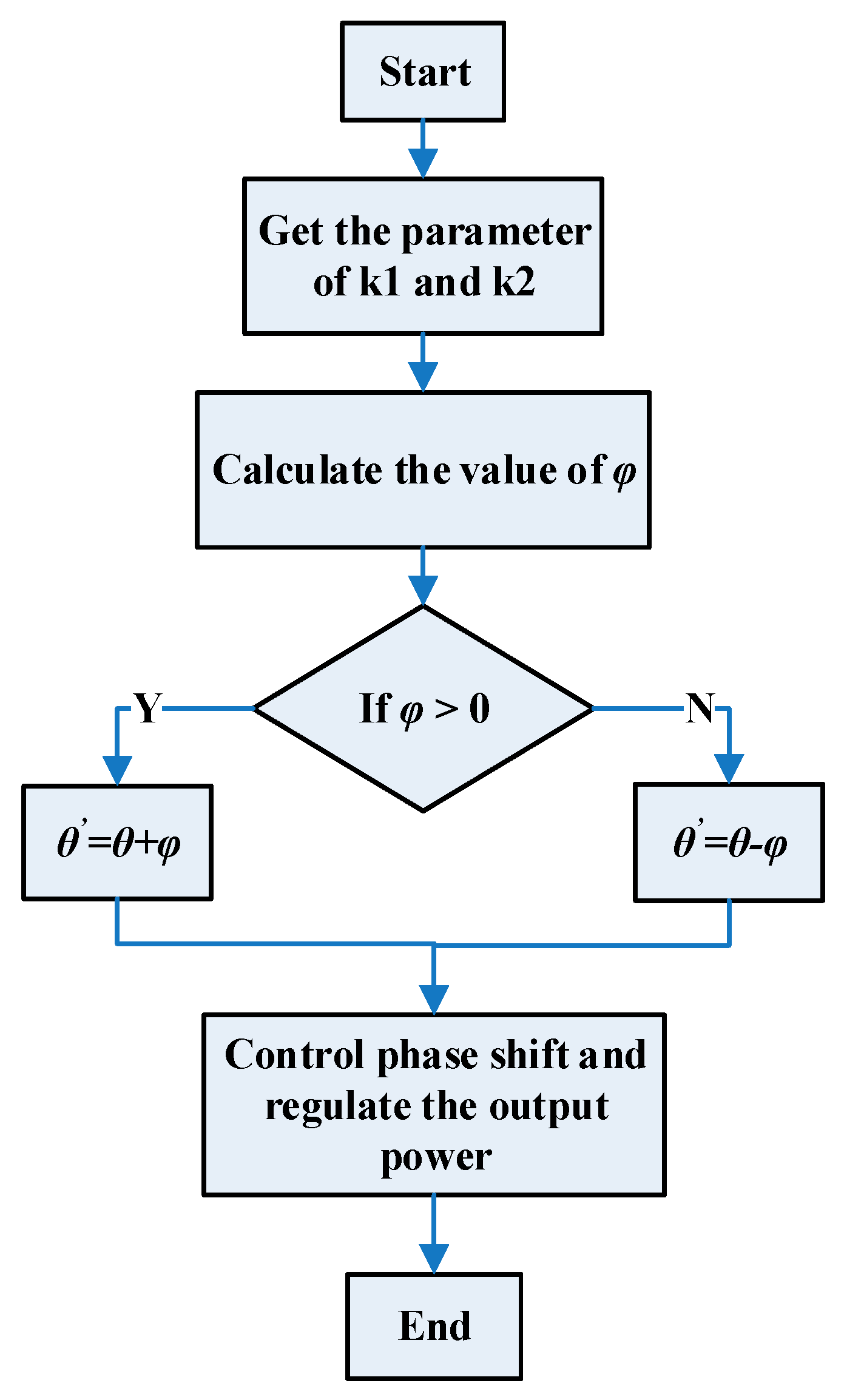
In Figure 4, the phase offset changes from 0 degrees to 18 degrees. From papers, mutual inductance could be calculated. Then, the phase offset could be determined by Formula (10). In order to eliminate the phase offset and realize the output power regulation, the flow chart of phase-shift is in Figure 5.
5. Analysis of System Output Under Parameters Variation
5.1. Influence of Load Variation on System
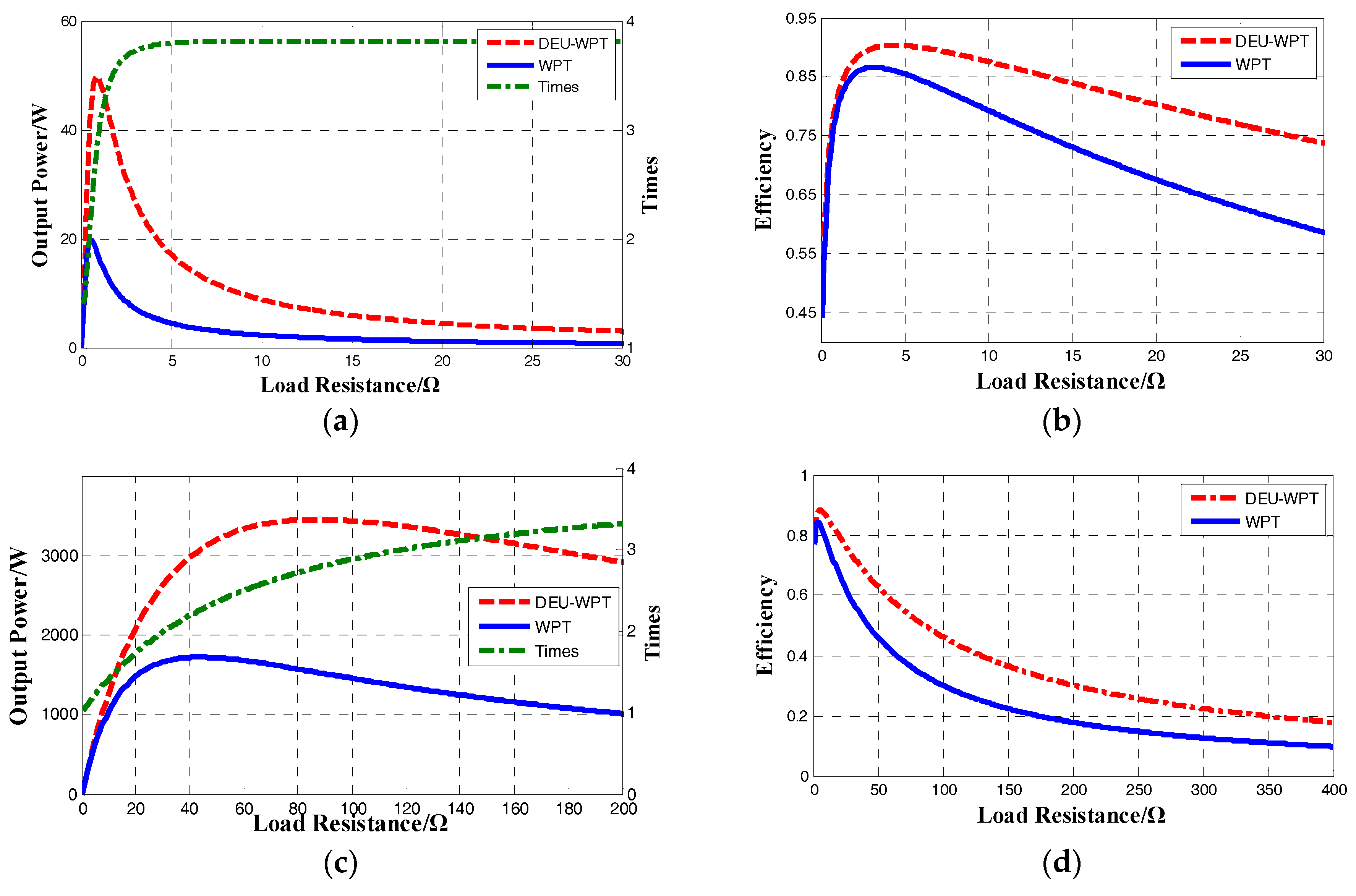
Figure 6 shows the comparison of the output power and efficiency in the case of load changes. The red line represents the DEU-WPT system, the blue line represents the general WPT system, and the green line represents the improving times of output power of DEU-WPT system compared to WPT system. The load is variable, and the other parameters remain unchanged when switch resistance is ignored.
For the PS-type DEU-WPT system, Figure 6a shows that the output power gain can reach four times that of a traditional WPT system, and it is easier to reach four times the output power with load changes than SS-type. Figure 6b shows that greater efficiency can be reached with the PS-type DEU-WPT than with the PS-type WPT. The efficiency of DEU-WPT is much more stable than WPT with the changes of load. However, for SS-type DEU-WPT in Figure 6c,d, once the reflection impedance is far less than the coil resistance, the primary resonant network will be in short circuit and the resonant current will bring heavy burden to the system so that the efficiency decreases more quickly.
5.2. Influence of Mutual Inductance on System
Normally, the cross-coupling inductance M12 is fixed in charging, but the lateral misalignment leads to the change of mutual inductance, as shown in Figure 7. Therefore, it is necessary to analyze the characteristic of output under the condition of mutual inductance variation.
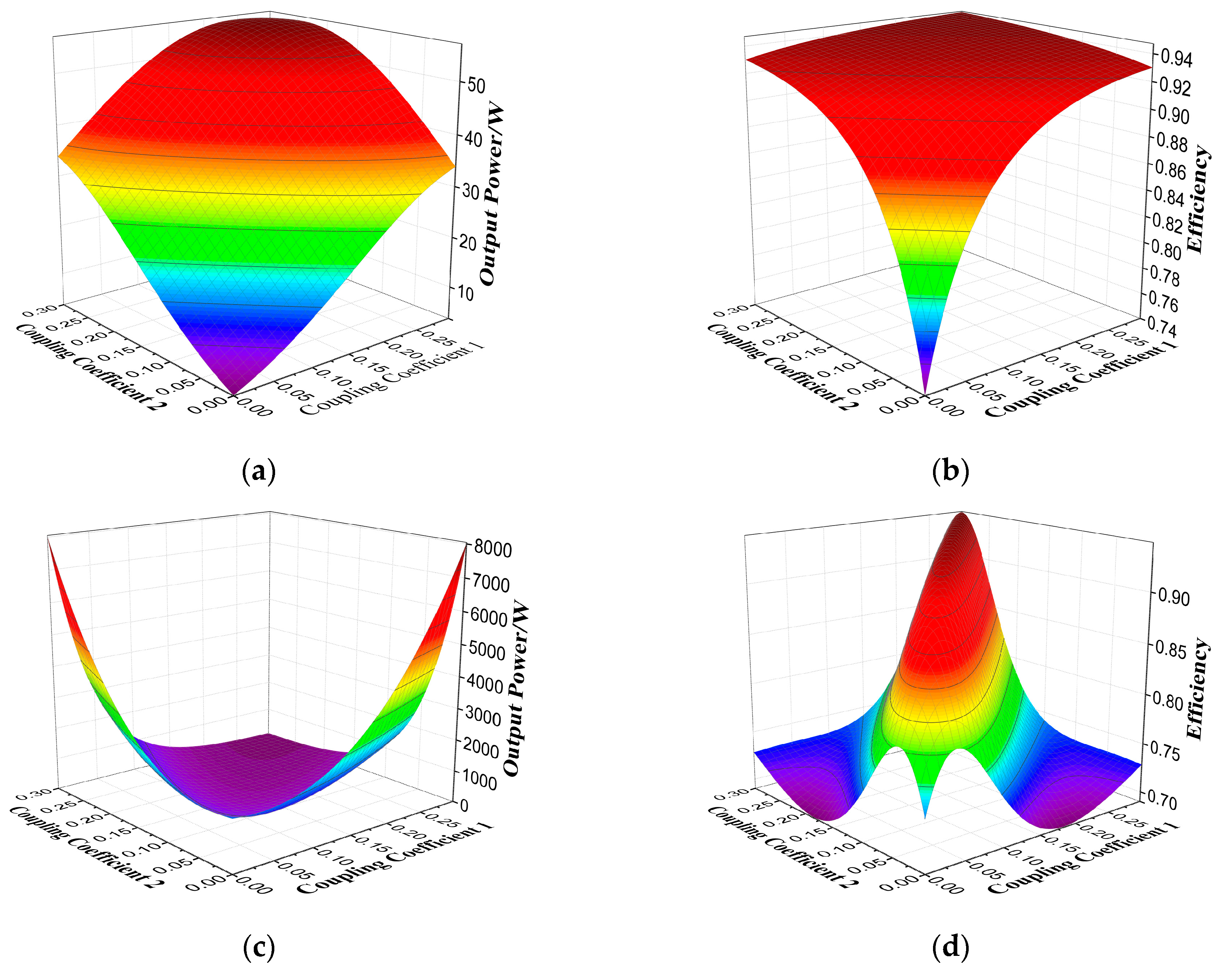
Figure 8 shows the output power under the change of mutual inductance. The x and y axis represents the coupling coefficient k1 and k2 between primary coil and secondary coil respectively. The cross-coupling coefficients k3 is fixed at 0.03.
From Figure 8, it can be seen that system can achieve optimum output power and efficiency with symmetrical coupling coefficient. Although the output power changes in the charging area that the two coupling coefficients are different, the efficiency could remain high. Compared with a general WPT system, the DEU-WPT system exhibits good adaptability. More specifically, for a PS-type DEU-WPT, the maximum output power and efficiency can be achieved simultaneously under the condition of constant load when there are no phase differences between currents in primary coils. From Figure 8c,d, when coupling coefficients are equal, the SS-type DEU-WPT shows high efficiency and the output power first increases and then decreases. However, when the coupling coefficient changes the output power improves, but the efficiency declines rapidly.
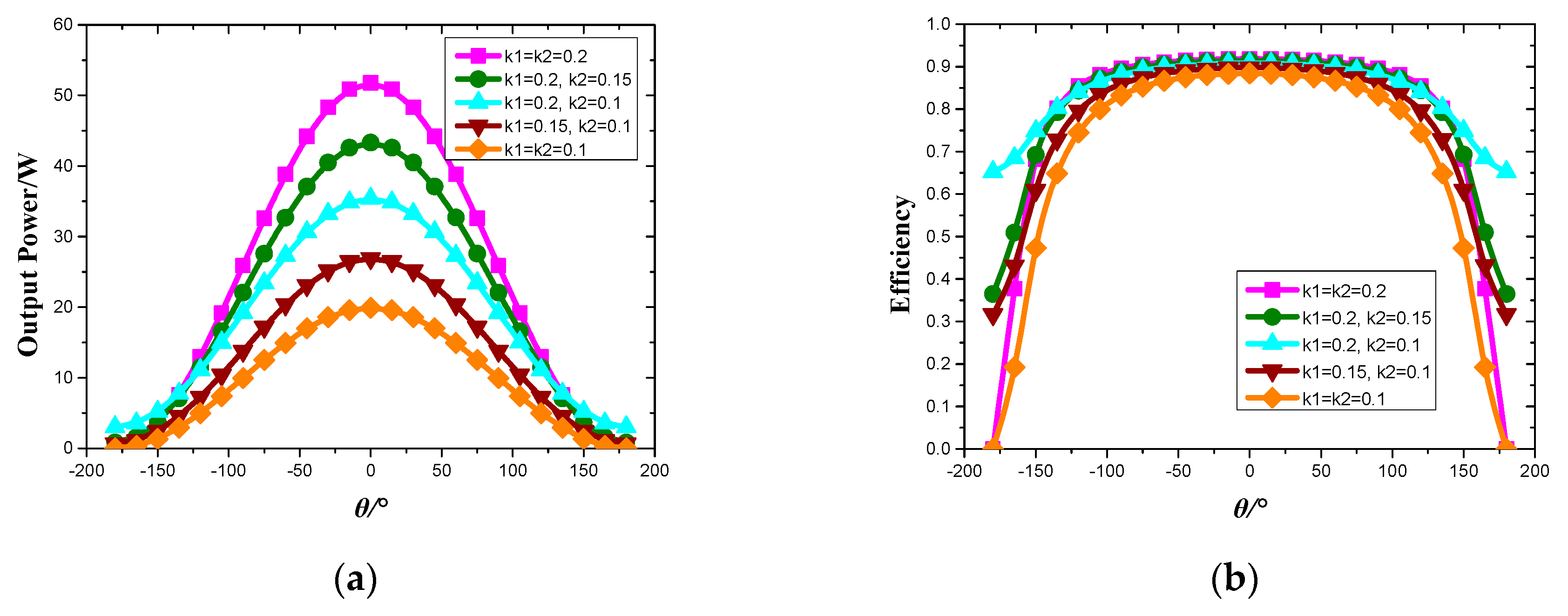
Figure 9 shows the curve of output power modulation and efficiency with phase shift variation under different coupling conditions, where the phase difference is from −180° to 180°.
In Figure 9, the output power is mainly affected by the coupling coefficient and θ. Compared with the general phase-shift method (which regulates the output power by changing the RMS of input voltage), the method proposed in this paper produces much less harmonics in resonant tank and achieves high-efficiency transmission by controlling the phase angle θ of voltage between the two coils. Moreover, compared to other systems which regulate output power by adding DC-DC module, the method proposed which only needs fewer devices to cut the costs reduces the complexity of system circuits and improves efficiency.
6. Simulation and Experimental Verification
6.1. Simulation Verification of Proposed System
The Simulink simulation model of the system is established by Matlab (MathWorks, Natick, MA, USA). This paper takes the PS-type DEU-WPT as an example to analyze. Set the controlled aim of system input voltage as Ein = 30 V, the operating frequency f = 20 kHz, the output load RL = 5 Ω, and secondary coil Ls = 210 μH. According to (6) and (7), other parameters are shown in Table 2. To compare with a WPT system with a single excitation unit, we set the same parameters of the traditional WPT system, as shown in Table 3.
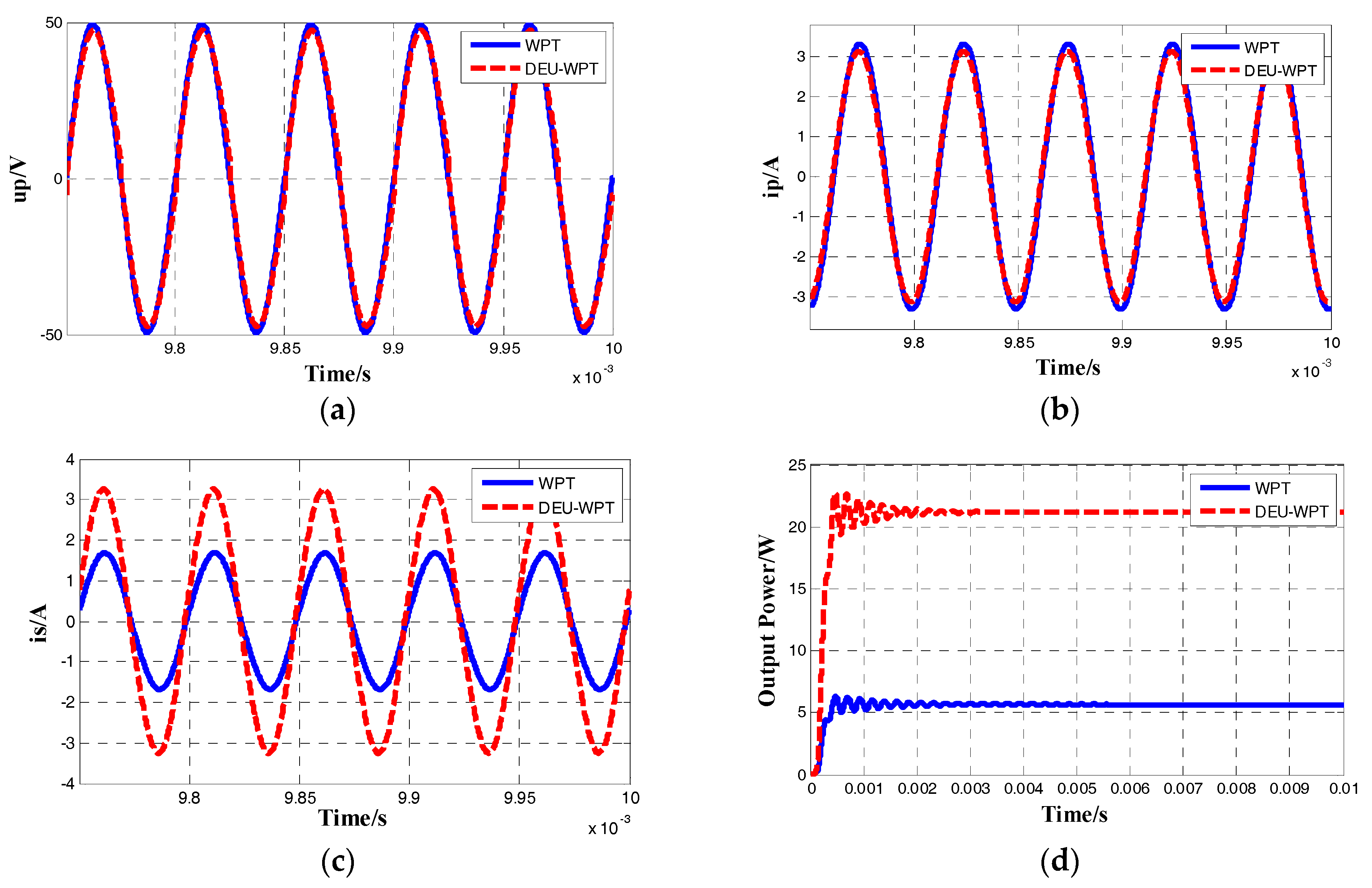
The resonant current ip, resonant voltage up, and output power Pout waveform comparison is shown in Figure 10, where up is the resonant voltage of the primary side, ip is the resonant current of the primary side, and is is the resonant current of the secondary side.
Figure 10 shows that the output power of the DEU-WPT system compared to the WPT system is increased by about four times compared to the traditional WPT system. Furthermore, due to the advantages of parallel structure, the cross-coupling inductance jωM12 and reflection impedance 2ω2M2/Ro on the branch of inductance ensures that the current stress of the PS-type DEU-WPT system is less than the traditional WPT system. Under the condition of improving power level, the RMS of the primary resonant current of DEU-WPT compared to the WPT is reduced by about 5%, the RMS of primary resonant voltage of DEU-WPT is reduced by about 4%, and the resonant current of DEU-WPT system’s pick-up side is almost doubled. Regarding cost, for higher-power application such as electrical vehicle (EV) charging, the cost of the DEU-WPT system will be lower than traditional WPT system at same power capacity level because the voltage and current stress equipment are lower than traditional WPT system.
6.2. Experimental Verification of the Proposed System
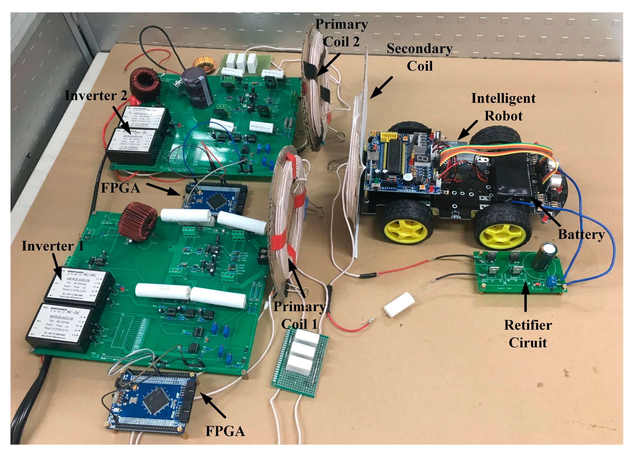
In this paper, the experimental tests are divided into two groups: one group is a PS-type WPT system, and the other is a PS-type DEU-WPT system. The an image of the DEU-WPT experimental device is shown in Figure 11, where the two primary coils are 14 cm in diameter. The secondary coil is placed in front of the robots (20 cm in diameter). The transmission distance between primary coils and secondary coil is about 4 cm, and for the two experimental systems’ parameters, refer to Table 1 and Table 2.
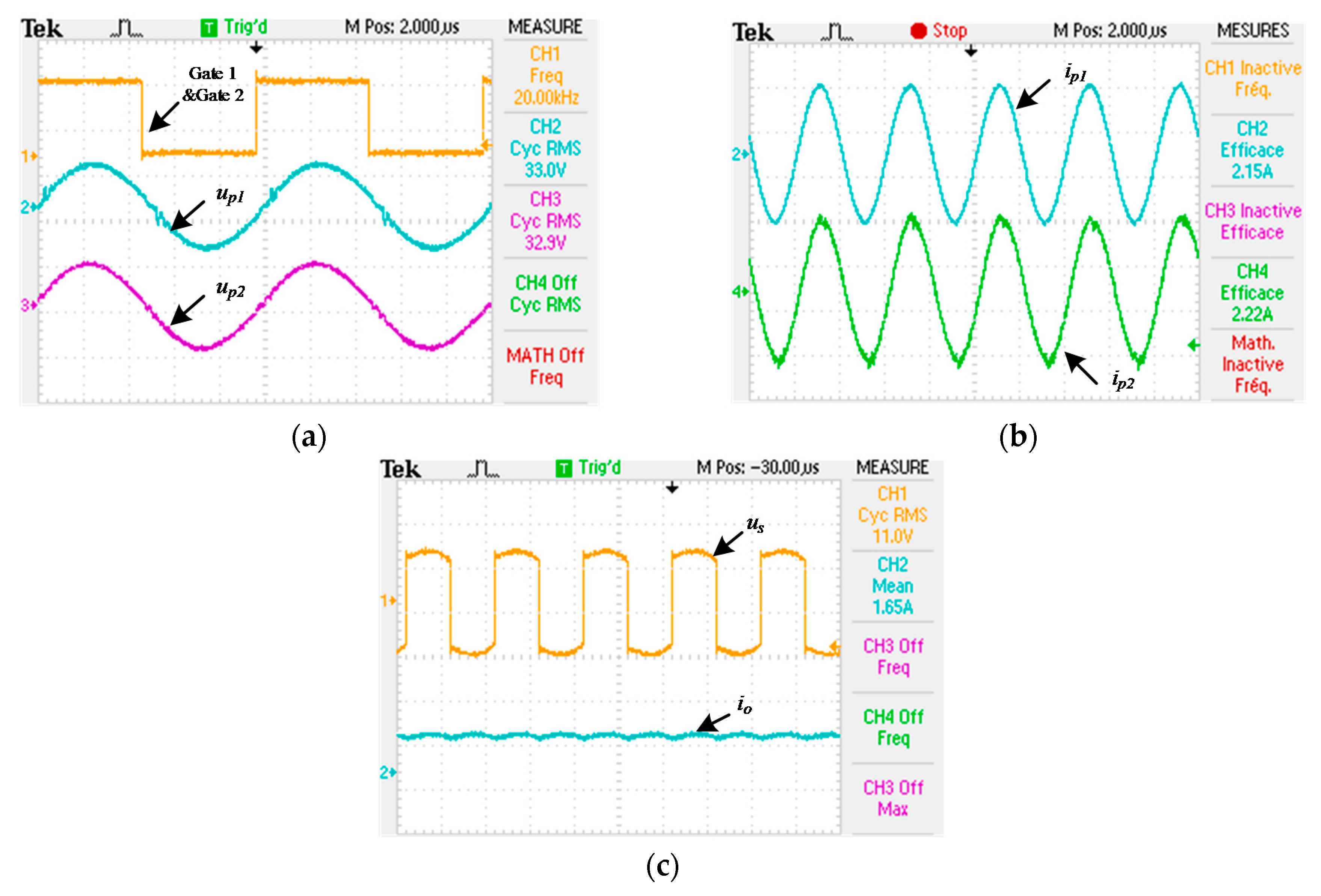
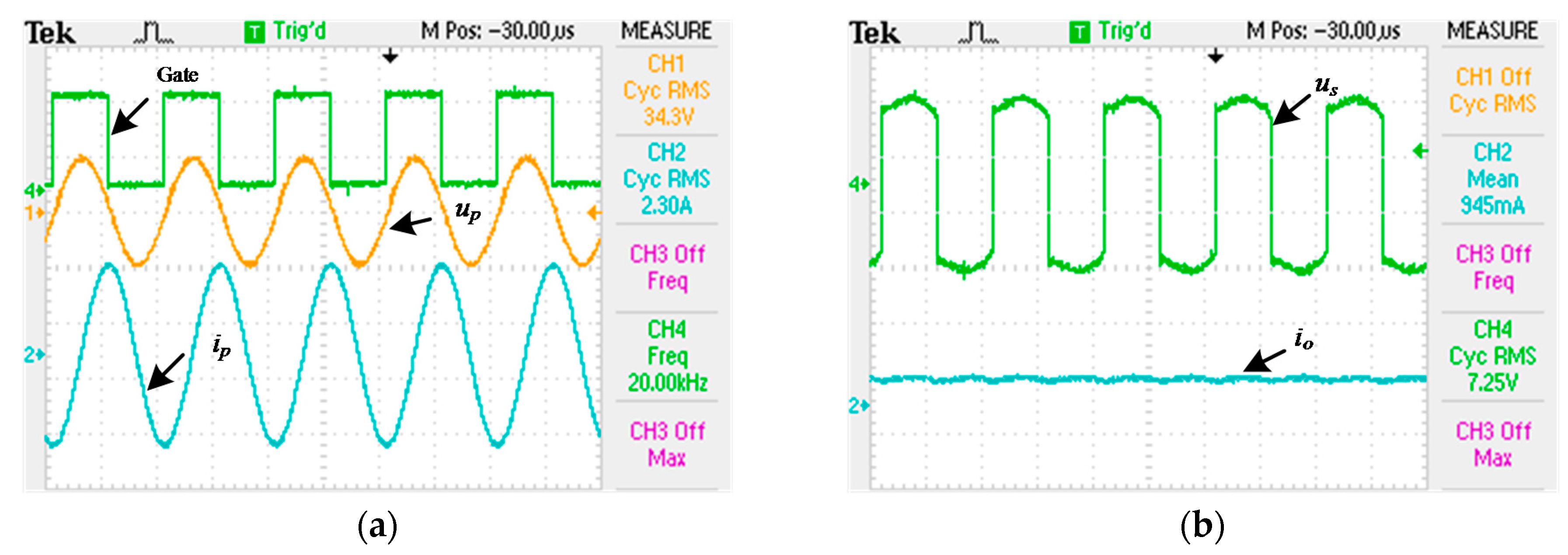
Figure 12 shows the experimental waveforms of the PS-type DEU-WPT system. The input voltage of the two systems are both 30 V, and the measured input currents are 0.30 A and 0.31 A, respectively. Figure 12a is the resonant voltage up1 and up2 of the two coils, which are fully synchronized with the driving signals given by FPGA (Field-Programmable Gate Array) in channel 1. The RMS of voltage is 33 V and 32.9 V respectively. The Figure 12b show the waveform of resonant current ip1 and ip2, the RMS of current are 2.15 A and 2.22 A. Figure 12c shows that the io is 1.65 A. According to the formula Pout = Ip2Ro, the output power of the DEU-WPT system is 14.5 W, and the efficiency is 80%.
Figure 13 shows the experimental waveforms of the PS-type WPT system. The input voltage of the system is 30 V, and the measured input current is 0.21 A. In Figure 13a, channel 1 is the driving signal of the inverter circuit which has 20 kHz frequency. ip is the resonant current waveform of the primary coil, and the RMS of current is 2.30 A. up is the resonant voltage waveform of the primary coil, and the RMS of voltage is 34.3 V. In Figure 13b, the mean value of output current of the rectifier circuit io is 0.945 A, and the output power is 4.5 W when the efficiency is 71.4%.
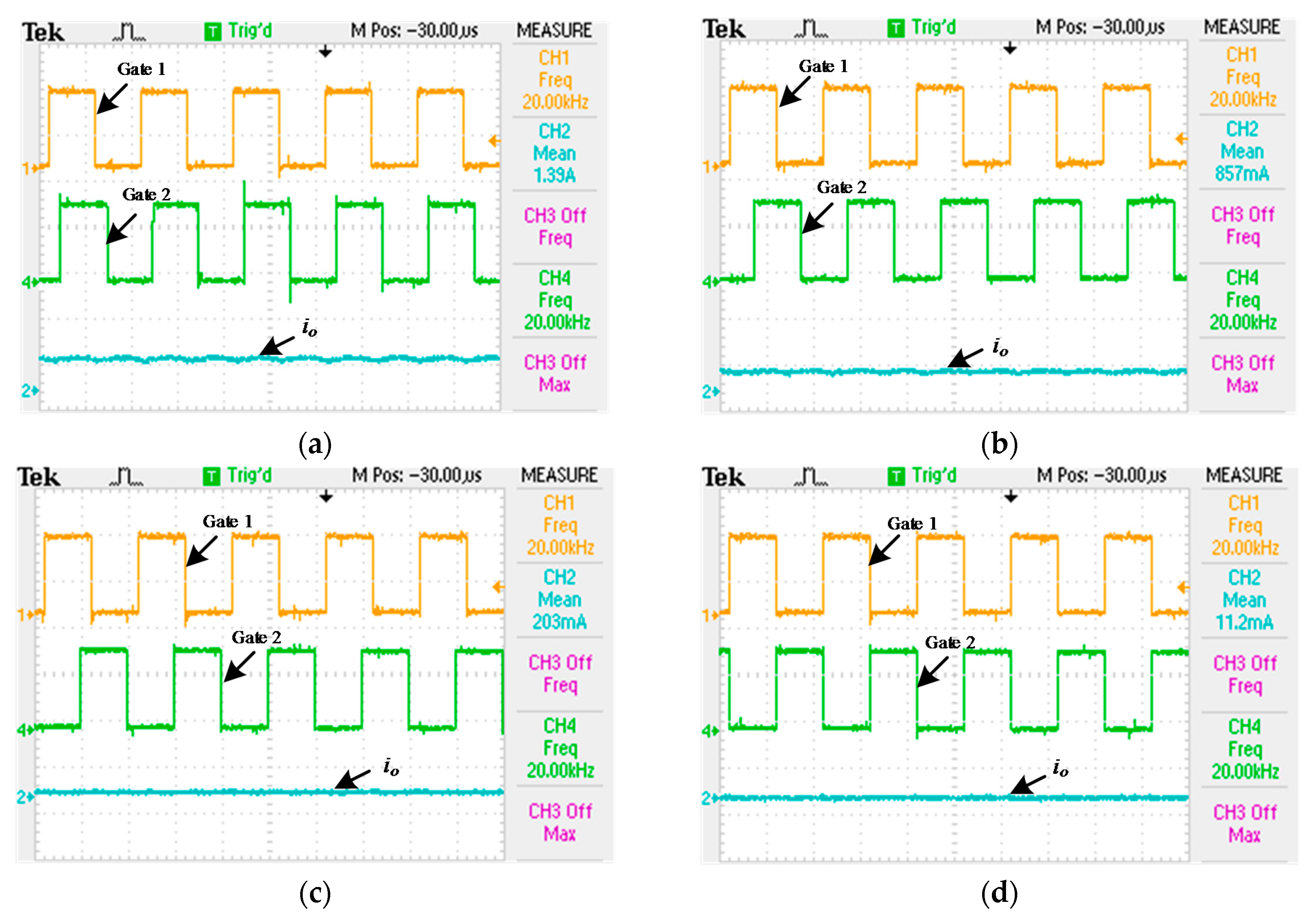
Several experiments were carried out for verification of output power regulation. Figure 14 shows the io when the θ of the DEU-WPT system is 45 degrees, 90 degrees, 135 degrees, and 180 degrees.
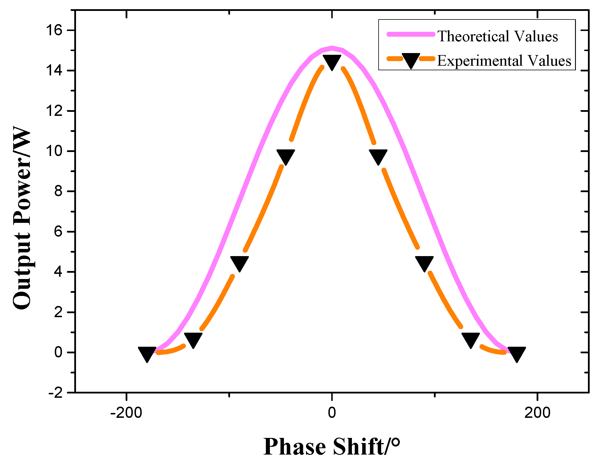
In Figure 12 and Figure 13, the output power has increased by 3.3 times compared with the WPT system, and the efficiency of the DEU-WPT system was improved by 9%. At the same time, the resonant voltage up and resonant current ip of the primary coil of the DEU-WPT decreased by 3.3% to 6% compared with WPT. The experimental results are consistent with the theoretical analysis. Table 4 shows the comparison of experimental results between WPT and DEU-WPT. Figure 15 shows the experimental result under phase-shift. As can be seen from Figure 15, the proposed power regulation method can be achieved.
7. Conclusions
In this paper, a DEU-WPT system for charging intelligent robots is built, and a method of output power modulation is proposed. Compared with traditional the WPT system, the DEU-WPT system has the following benefits: (1) Compared to the traditional system, output characteristics of the PS-type DEU-WPT have been improved significantly. Not only can output power of DEU-WPT increase by 3.3 times, but the efficiency of DEU-WPT has also increased by 9%. The reliability of the system has enhanced. (2) The power modulation is realized by the current phase control of the primary coil, which reduces the harmonics and improves the flexibility of the system. (3) Reducing the stress of voltage and current of the primary resonant network enhances the security of the system. (4) The PS-type DEU-WPT system is more stable than PS-type WPT for intelligent robots in both dynamic charging and static charging. In summary, the DEU-WPT system has advantages compared with the traditional system, providing a new method to improve the output characteristics of robot charging based on wireless power transfer, and provides a new way to solve the system security problem.
By comparing with the traditional WPT topology, it is found that the DEU-WPT system can significantly increase output power and efficiency while reducing the stress of voltage and current in the resonant network. At the same time, the DEU-WPT is more robust than general WPT system under the condition of parameter variation.
Acknowledgments
The research is supported by National Natural Science Foundation of China (51377183), Chongqing International Science and Technology Cooperation Base Project (CSTC2015GJHZ40001) and the Fundamental Research Funds for the Central Universities (106112016CDJZR175510).
Author Contributions
The main idea of this paper was proposed by Xin Dai and Jincheng Jiang. Jincheng Jiang wrote this paper. Xin Dai, Yanling Li and Ting Yang gave experiment design. Jincheng Jiang, Yanling Li and Ting Yang performed verification experiments.
Conflicts of Interest
The authors declare no conflict of interest.
References
- Kim, D.; Kim, M.; Yoo, J.; Park, H.H.; Ahn, S. Magnetic resonant wireless power transfer for propulsion of implantable micro-robot. J. Appl. Phys. 2015, 117, 1–4. [Google Scholar] [CrossRef]
- Rao, S.; Chiao, J.C. Body Electric: Wireless Power Transfer for Implant Applications. IEEE Microw. Mag. 2015, 16, 54–64. [Google Scholar] [CrossRef]
- Lee, K.H.; Jun, B.O.; Kim, S.; Lee, G.J.; Ryu, M.; Choi, J.W.; Jang, J.E. A study on geometry effect of transmission coil for micro size magnetic induction coil. Solid-State Electron. 2016, 119, 45–49. [Google Scholar] [CrossRef]
- Budhia, M.; Boys, J.T.; Covic, G.A.; Huang, C.Y. Development of a Single-Sided Flux Magnetic Coupler for Electric Vehicle IPT Charging Systems. IEEE Trans. Ind. Electron. 2013, 60, 318–328. [Google Scholar] [CrossRef]
- Madawala, U.K.; Thrimawithana, D.J. Modular-based inductive power transfer system for high-power applications. IET Power Electron. 2012, 5, 1119–1126. [Google Scholar] [CrossRef]
- Zhong, W.X.; Liu, X.; Hui, S.Y.R. A Novel Single-Layer Winding Array and Receiver Coil Structure for Contactless Battery Charging Systems With Free-Positioning and Localized Charging Features. Trans. Ind. Electron. 2011, 58, 4136–4144. [Google Scholar] [CrossRef]
- Ke, Q.; Luo, W.; Yan, G.; Yang, K. Analytical Model and Optimized Design of Power Transmitting Coil for Inductive Coupled Endoscope Robot. IEEE Trans. Biomed. Eng. 2015, 63, 694–706. [Google Scholar] [CrossRef] [PubMed]
- Assaf, T.; Stefanini, C.; Dario, P. Autonomous Underwater Biorobots: A Wireless System for Power Transfer. IEEE Robot. Autom. Mag. 2013, 20, 26–32. [Google Scholar] [CrossRef]
- Oruganti, S.K.; Sang, H.H.; Ma, H.; Bien, F. Wireless Energy Transfer: Touch/Proximity/Hover Sensing for Large Contoured Displays and Industrial Applications. IEEE Sens. J. 2015, 15, 2062–2068. [Google Scholar] [CrossRef]
- Liu, C.; Ge, S.; Guo, Y.; Li, H.; Cai, G. Double-LCL resonant compensation network for electric vehicles wireless power transfer: Experimental study and analysis. IET Power Electron. 2016, 9, 2262–2270. [Google Scholar] [CrossRef]
- Li, Y.L.; Sun, Y.; Dai, X. Robust control for an uncertain LCL resonant ICPT system using LMI method. Control Eng. Pract. 2013, 21, 31–41. [Google Scholar] [CrossRef]
- Zhu, Q.; Wang, L.; Guo, Y.; Liao, C.; Li, F. Applying LCC Compensation Network to Dynamic Wireless EV Charging System. IEEE Trans. Ind. Electron. 2016, 63, 6557–6567. [Google Scholar] [CrossRef]
- Feng, H.; Cai, T.; Duan, S.; Zhao, J.; Zhang, X.; Chen, C. An LCC-Compensated Resonant Converter Optimized for Robust Reaction to Large Coupling Variation in Dynamic Wireless Power Transfer. IEEE Trans. Ind. Electron. 2016, 63, 6591–6601. [Google Scholar] [CrossRef]
- Hao, H.; Covic, G.A.; Boys, J.T. A Parallel Topology for Inductive Power Transfer Power Supplies. IEEE Trans. Power Electron. 2011, 29, 2027–2034. [Google Scholar]
- Mai, R.; Li, Y.; Lu, L.; He, Z. A Power Regulation and Harmonic Current Elimination Approach for Parallel Multi-Inverter Supplying IPT Systems. J. Power Electron. 2016, 16, 1245–1255. [Google Scholar] [CrossRef]
- Zhou, S.; Mi, C. Multi-Paralleled LCC Reactive Power Compensation Networks and Their Tuning Method for Electric Vehicle Dynamic Wireless Charging. IEEE Trans. Ind. Electron. 2016, 63, 6546–6556. [Google Scholar] [CrossRef]
- Duan, Q.; Li, Y.; Dai, X.; Zou, T. A Novel High Voltage Output Gain Push-Pull Circuit for Inductively Coupled Power Transfer System. Energies 2017, 10, 474. [Google Scholar] [CrossRef]
- Geng, Y.; Yang, Z.; Lin, F.; Wang, Y. Maximum Power and Efficiency Transmission Using Parallel Energy Storage Load for Wireless Power Transfer Systems. In Proceedings of the 2017 IEEE PELS Workshop on Emerging Technologies: Wireless Power Transfer, Chongqing, China, 20–22 May 2017; pp. 70–74. [Google Scholar]
- Kobayashi, D.; Imura, T.; Hori, Y. Real-time Coupling Coefficient Estimation and Maximum Efficiency Control on Dynamic Wireless Power Transfer for Electric Vehicles. In Proceedings of the 2015 IEEE PELS Workshop on Emerging Technologies: Wireless Power, Daejeon, South Korea, 5–6 June 2015; pp. 004650–004655. [Google Scholar]
Figure 1.
Dual excitation unit wireless power transfer (DEU-WPT) system.

Figure 2.
Equivalent circuit model of DEU-WPT system.

Figure 3.
Phase-shifted regulation mode.

Figure 4.
Phase offset φ under the change of mutual inductance in DEU-WPT system.

Figure 5.
Flow chart of power regulation by phase-shift.

Figure 6.
Output characteristics under system load variation: (a) The output power of PS-type (Primary Parallel Secondary Series) system under load changes; (b) The efficiency of PS-type system under load changes; (c) The output power of SS-type (Primary Series Secondary Series) system under load changes; (d) The efficiency of SS-type system under load changes.

Figure 7.
The diagram of coupling coefficients changes.

Figure 8.
Output characteristics under mutual inductance variation of DEU-WPT: (a) Output power under mutual inductance variation of PS-type DEU-WPT; (b) Efficiency under mutual inductance variation of PS-type DEU-WPT; (c) Output power under mutual inductance variation of SS-type DEU-WPT; (d) Efficiency under mutual inductance variation of SS-type DEU-WPT.

Figure 9.
Curve of output power and efficiency with phase shift: (a) Curve of output power with phase shift; (b) Curve of efficiency with phase shift.
Figure 9.
Curve of output power and efficiency with phase shift: (a) Curve of output power with phase shift; (b) Curve of efficiency with phase shift.

Figure 10.
Comparison of simulation result: (a) Comparison of the primary resonant voltage of the system; (b) Comparison of the primary resonant current of the system; (c) Comparison of the secondary resonant current of the system; (d) Comparison of the output of the system.
Figure 10.
Comparison of simulation result: (a) Comparison of the primary resonant voltage of the system; (b) Comparison of the primary resonant current of the system; (c) Comparison of the secondary resonant current of the system; (d) Comparison of the output of the system.

Figure 11.
Experimental set-up.

Figure 12.
Experiment results of the DEU-WPT system: (a) Voltage waveform of the primary coil in DEU-WPT; (b) Current waveform of the primary coil in DEU-WPT; (c) Load waveform in DEU-WPT system.
Figure 12.
Experiment results of the DEU-WPT system: (a) Voltage waveform of the primary coil in DEU-WPT; (b) Current waveform of the primary coil in DEU-WPT; (c) Load waveform in DEU-WPT system.

Figure 13.
The experimental results of the WPT system: (a) Waveform of the primary coil in WPT system; (b) Waveform of load in WPT system.
Figure 13.
The experimental results of the WPT system: (a) Waveform of the primary coil in WPT system; (b) Waveform of load in WPT system.

Figure 14.
Experimental verification of power modulation: (a) 45 degrees phase difference; (b) 90 degrees phase difference; (c) 135 degrees phase difference; (d) 180 degrees phase difference.
Figure 14.
Experimental verification of power modulation: (a) 45 degrees phase difference; (b) 90 degrees phase difference; (c) 135 degrees phase difference; (d) 180 degrees phase difference.

Figure 15.
The experiment results under phase-shift.


Table 1.
Comparison between classical WPT and DEU-WPT.
| Parameter | PS Topology WPT | PS Topology DEU-WPT |
|---|---|---|
| Zrs | ||
| up | ||
| ip | ||
| is | ||
| Po | ||
| η |
Table 2.
Main simulation parameters of PS-type DEU-WPT system.
| Parameters | Values | Parameters | Values |
|---|---|---|---|
| Lp | 116 μH | Ls | 210 μH |
| Rp | 0.13 Ω | Rs | 0.3 Ω |
| Cp | 0.52 μF | Cs | 0.3 μF |
| Ein | 30 V | RL | 5 Ω |
| Ldc | 1 mH | M1 | 17 μH |
| M12 | 3 μH | M2 | 17 μH |
Table 3.
Main simulation parameters of PS-type WPT system.
| Parameters | Values | Parameters | Values |
|---|---|---|---|
| Lp | 116 μH | Ls | 210 μH |
| Rp | 0.13 Ω | Rs | 0.2 Ω |
| Cp | 0.54 μF | Cs | 0.3 μF |
| Ein | 30 V | Ldc | 1 mH |
| M | 17 μH | RL | 5 Ω |
Table 4.
Comparison of experimental results.
| Parameters | WPT | DEU-WPT |
|---|---|---|
| Ein | 30 V | 30 V |
| up | 34.3 V | 32.9 V/33 V |
| ip | 2.3 A | 2.15 A/2.22 A |
| is | 0.945 A | 1.65 A |
| Pout | 4.5 W | 14.5 W |
| η | 71.4% | 80% |
© 2017 by the authors. Licensee MDPI, Basel, Switzerland. This article is an open access article distributed under the terms and conditions of the Creative Commons Attribution (CC BY) license (http://creativecommons.org/licenses/by/4.0/).
Share and Cite
MDPI and ACS Style
Dai, X.; Jiang, J.; Li, Y.; Yang, T. A Phase-Shifted Control for Wireless Power Transfer System by Using Dual Excitation Units. Energies 2017, 10, 1000. https://doi.org/10.3390/en10071000
AMA Style
Dai X, Jiang J, Li Y, Yang T. A Phase-Shifted Control for Wireless Power Transfer System by Using Dual Excitation Units. Energies. 2017; 10(7):1000. https://doi.org/10.3390/en10071000
Chicago/Turabian StyleDai, Xin, Jincheng Jiang, Yanling Li, and Ting Yang. 2017. "A Phase-Shifted Control for Wireless Power Transfer System by Using Dual Excitation Units" Energies 10, no. 7: 1000. https://doi.org/10.3390/en10071000
Note that from the first issue of 2016, this journal uses article numbers instead of page numbers. See further details here.