Regenerative Braking Control Strategy of Electric-Hydraulic Hybrid (EHH) Vehicle

1
State Key Laboratory of Mechanical Transmission, Chongqing University, Chongqing 400044, China
2
School of Automotive Engineering, Chongqing University, Chongqing 400044, China
*
Author to whom correspondence should be addressed.
Energies 2017, 10(7), 1038; https://doi.org/10.3390/en10071038
Submission received: 9 June 2017
/
Revised: 11 July 2017
/
Accepted: 13 July 2017
/
Published: 20 July 2017
(This article belongs to the Special Issue Advances in Electric Vehicles and Plug-in Hybrid Vehicles 2017)
Abstract
:A novel electric-hydraulic hybrid drivetrain incorporating a set of hydraulic systems is proposed for application in a pure electric vehicle. Models of the electric and hydraulic components are constructed. Two control strategies, which are based on two separate rules, are developed; the maximum energy recovery rate strategy adheres to the rule of the maximization of the braking energy recovery rate, while the minimum current impact strategy adheres to the rule of the minimization of the charge current to the battery. The simulation models were established to verify the effects of these two control strategies. An ABS (Anti-lock Braking System) fuzzy control strategy is also developed and simulated. The simulation results demonstrate that the developed control strategy can effectively absorb the braking energy, suppress the current impact, and assure braking safety.
1. Introduction
In the face of environmental crisis and pressure on energy sources, electric vehicles (EVs) have received significant attention. The advantage of the electric vehicle is that its energy storage system, which is a battery, has high energy density and a very large storage capacity [1]; also, advanced battery technology gives the batteries a longer service life [2]. For enhancing energy efficiency, electric vehicles use a regenerative braking system to recover part of the braking energy. However, in certain braking conditions, the feedback current generated by the generator is substantially high [3]. The high charge current is likely to shorten the cycle life of the battery [4,5]. On the other hand, owing to restriction from the characteristics of the motor and battery, the energy recovery rate of the motor-battery energy storage system is not significantly high [6]. The high cost of batteries and the limitations on using them in heavy vehicles are also limitations on the electric vehicle [7].
The hydraulic energy storage system has the characteristics of a high power density device (the hydraulic accumulator), although its energy density is significantly lower [8]; this accords it the potential to overcome the shortcomings of an electric energy storage system. The hydraulic system is used to absorb the high-power braking energy and release the stored energy during start-up or acceleration. This has the potential to increase energy efficiency and decrease over-current; thus, the driving range of the vehicle and the cycle life of the battery are increased.
The hydraulic energy storage system has been used in conventional ICE (Internal Combustion Engine) vehicles to improve their fuel economy. In 2004, Eaton Corporation presented its hydraulic hybrid vehicle in cooperation with Ford in the SAE (Society of Automotive Engineers) world congress [9]. The hydraulic system can store and re-deliver about 80% of braking kinetic energy back to the wheels (Figure 1a). In 2013, the PSA (Peugeot Société Anonyme) put the hydraulic system into a passenger car (Figure 1b). This hydraulic hybrid system (which was called ‘Hybrid Air’) was claimed to reduce fuel consumption by 45% in urban driving [10]. These successful and efficient applications of a hydraulic system demonstrated the enormous advantage of a hydraulic energy storage system.
In this study, a set of hydraulic energy storage systems was incorporated to electric vehicles to construct a novel electric-hydraulic hybrid (EHH) system, and the parameters of this system were evaluated [11]. Considering two aspects of the electric-hydraulic hybrid system, energy recovery rate and current impact, two types of braking force distribution control strategies were designed. They are based on two separate rules; the maximum braking energy recovery rate and the minimum current impact. In the control strategy based on maximum energy recovery rate, the hydraulic braking system was operated first. The electric system operated after the hydraulic system had absorbed adequate energy, and the speed of the vehicle had declined to a value suitable for the electric motor. By this strategy, the regenerative braking system can absorb an optimum amount of braking energy. In the control strategy based on minimum current impact, the charge current is first considered. The electric regenerative braking force is adjusted by regulating the hydraulic braking and friction braking in order to regulate the feedback current to within a specified value without rapid fluctuations. The coordination of regeneration braking and ABS (Anti-lock Braking System) control is also simulated in this study. The results show the effectiveness of a designed control strategy. The energy recovery rate is much higher under the maximum braking energy recovery rate, while there is still some degree of over-current; the charging current to the battery is gentle while the energy recovery rate is not very high. The regenerative braking system and the ABS coordinate well; regenerative braking quits when the ABS is triggered.
2. Structure of the Electric-Hydraulic Hybrid System
The new electric-hydraulic hybrid powertrain is a parallel-hybrid system, which incorporates a traction motor, battery pack, hydraulic pump/motor (secondary component), hydraulic accumulator, reservoir, and a series of hydraulic valves, as illustrated in Figure 1.
The hydraulic circuit includes the driving circuit and the unloading circuit, as illustrated in Figure 2. The driving circuit is composed of a cartridge valve (2), a one-way valve (3), and a two-position four-way valve (1). To apply the vehicle’s brakes, valve 1 is shifted to the left position; this directs oil from the reservoir to flow toward the accumulator using the secondary component pump/motor. The secondary component operates in the pump mode using the vehicle’s kinetic energy to apply pressure on the oil in the reservoir in order for it to flow into the accumulator. The energy is stored in the accumulator, and the vehicle slows down. The hydraulic system operated in the regenerative braking mode.
When the vehicle requires acceleration, valve 1 is shifted to the right position; this directs the high-pressure oil in the accumulator to flow through the cartridge valve 2. The accumulator releases the high-pressure oil to drive the hydraulic secondary component (which operates as motor), which is connected to the front axle, thus accelerating the vehicle. The hydraulic system operated in driving mode. The hydraulic system does not operate when the vehicle is in cruising mode. The clutch engages if the hydraulic system is required.
3. Models of the Main Components
3.1. Electric Motor Model
In the electric-hydraulic hybrid system, the electric motor and battery are the driving components as well as the key elements in regenerative braking. Considering the limitations on the generation of efficiency and speed, the braking torque that the electric motor could provide is:
where TM_max is the maximum braking torque of the electric motor (Nm), PM_max is the maximum output power of the motor (kW), n is the rotational speed (r/min), nb is the base speed of the motor, and ηM is the efficiency of the motor.
When the rotational speed of the motor is lower than a specified value, the generation efficiency and energy recovery rate are substantially low. At this time, the electric motor for regenerative braking is to shut down.
3.2. Battery Character
In the charging process of the battery, the charging power can be expressed as:
where UB is the terminal voltage of the battery and Ichrg is the charge current. Considering the charging efficiency of the battery, , the relation between the charge current and the motor braking torque can be obtained as follows:
3.3. Secondary Component (Hydraulic Pump/Motor) Model
The hydraulic system is incorporated to the pure electric vehicle in order to absorb the high power-density braking energy while braking. The components of the hydraulic system significantly affect the braking performance and the energy recovery rate.
The torque of the secondary component (hydraulic pump/motor) is:
where Δp is the working pressure of the secondary component, Vp/m is the displacement, and ηp/m is the efficiency of the secondary component. With regard to the swash-plate axial piston pump, the output torque can be altered by adjusting the displacement .
3.4. Hydraulic Accumulator Model
In the braking process, the gas in the accumulator can be assumed to be undergoing an adiabatic process. The pressure and the volume of the gas satisfy the gas state equation:
where n is the polytropic exponent value. In an adiabatic process, n = 1.4. p0 is the pre-charging pressure, p1 is the minimum working pressure, p2 is the maximum working pressure, V0 is the volume of the gas when pressure is p0, V1 is the gas volume when pressure is p1, and V2 is the gas volume when pressure is p2.
The maximum energy that the accumulator is capable of recovering is:
Therefore, the energy that the accumulator is capable of absorbing is related to the final gas pressure.
3.5. Vehicle Braking Dynamic Model
In this electric hydraulic hybrid system, there are three parts of the braking force in the front axle; the hydraulic regenerative braking force provided by the hydraulic pump/motor Fpreg, the electric regenerative braking force provided by the electric motor Fmreg, and friction Fffric. In the rear axle, the friction provides all of the braking force. They combine together to provide the required braking force:
where Fz is the total braking force; . Here, u is the velocity of the vehicle and is the coefficient of rotational mass. The air resistance is not considered as it is negligible compared with the other forces.
Considering the transmission ratio of the powertrain, the following is obtained:
where i0 is the speed ratio of the transmission, ig is the speed ratio of the final drive, ic is the speed ratio of the coupling mechanism, and r is the radius of the wheels.
The braking force is to be distributed between the front axle and the rear axle according to the distribution ratio β; hence
4. Control Strategy Design
4.1. Braking Mode Judgment
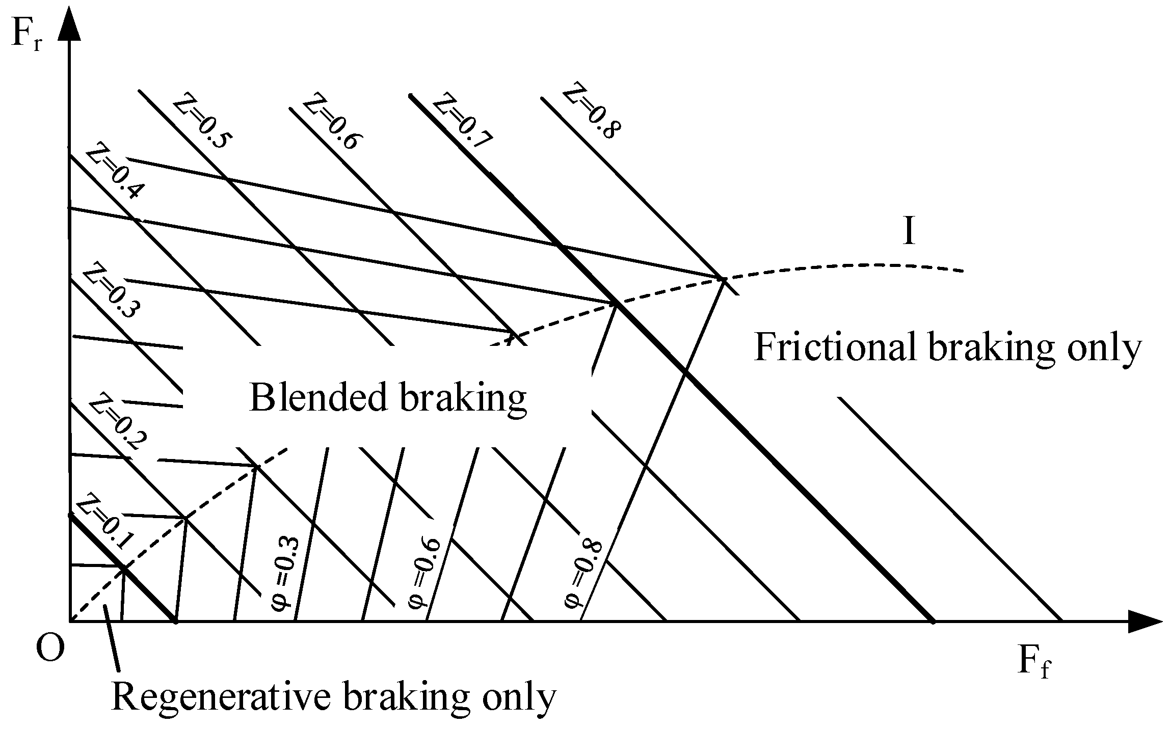
According to the ECE R13 (Regulation No 13 of the Economic Commission for Europe) braking regulation [15], the braking force can be completely provided by the front wheel during low intensity braking. Substituting the distribution ratio β = 1 into the ECE regulation formula (Equation (10)), the low braking intensity threshold zm = 0.1 [14,16].
where z is the braking strength (z = a/g; a is the braking deceleration and g is the gravity acceleration, g ≈ 9.81 m/s2), L is the wheelbase, L2 is the distance from the mass center to the rear axle, and hg is the height of the mass center.
When z = a/g is less than 0.1, the braking is judged as low intensity braking. The braking force is provided by regenerative braking in the front axle; when 0.1 < z < 0.7, the braking is judged as medium intensity braking, and the braking force is provided by both regenerative braking and frictional braking. When z > 0.7, the braking is judged as high intensity braking, which means that the vehicle is in an emergency braking state. For safety reasons, the braking process is totally accomplished by frictional braking (Figure 3).
4.2. Control Strategy Based on Maximum Energy Recovery Rate
There are three types of braking force in the braking process of the electro-hydraulic hybrid system; hydraulic regenerative braking, electric regenerative braking, and friction. The additional hydraulic system is used to absorb the high-power braking energy in the initial stage of the braking or to reduce the current impact. This study designed two types of distribution method by following two separate principles; the maximum braking energy recovery rate and the minimum charge current impact.
Figure 4 illustrates the braking force distribution strategy, which adheres to the maximum energy recovery rate principle:
- (1)
- According to the braking demand from the driver, the distribution ratio β is designated. If a/g < 0.1 and β = 1, the front wheels alone provide the braking force; if a/g > 0.1, β = 0.689, the braking force is distributed between the front and rear axles in the ratio β.
- (2)
- If the pressure of the accumulator is higher than its maximum allowed value, the hydraulic regenerative braking system is not activated.
- (3)
- If the hydraulic regenerative braking force can cover the braking demand in the front axle, the braking force in the front is completely provided by the hydraulic system (for example, point A in Figure 4b); otherwise, the hydraulic system provides its maximum allowed value.
- (4)
- If the electric regenerative braking force can cover the insufficient force, the insufficient force is provided by electric braking; otherwise, the electric system provides its maximum.
- (5)
- If the hydraulic braking force and electric braking force together are insufficient, the friction force contributes the insufficient part (for example, point C in Figure 4b).
When the braking process is about to end, the vehicle speed becomes too low for the electric motor to generate feedback current. Then, the vehicle is stopped by friction force.
During the process of shifting between the two types of braking force, the increasing rate is to be equal to the decreasing rate. For example, in the braking process, at the time the accumulator is about to attain its maximum pressure, the hydraulic system is to quit braking while the electric braking system (or friction braking system) is to begin participating in the braking process. The rate of decrease of the hydraulic braking force is to be equal to the rate of increase of the electric braking force (or friction force).
4.3. Control Strategy Based on Minimum Current Impact
With respect to the Li-ion batteries used in electric vehicles, the over-charge current reduces the capacity and cycle life of the batteries. According to a few of the existing results, at the charging rate of 2 C, the battery capacity is reduced by 50% after a number of cycles [17]. Considering both energy recovery and current impact, this study set the maximum charge current as 1 C, which implies that Imax = 70 A.
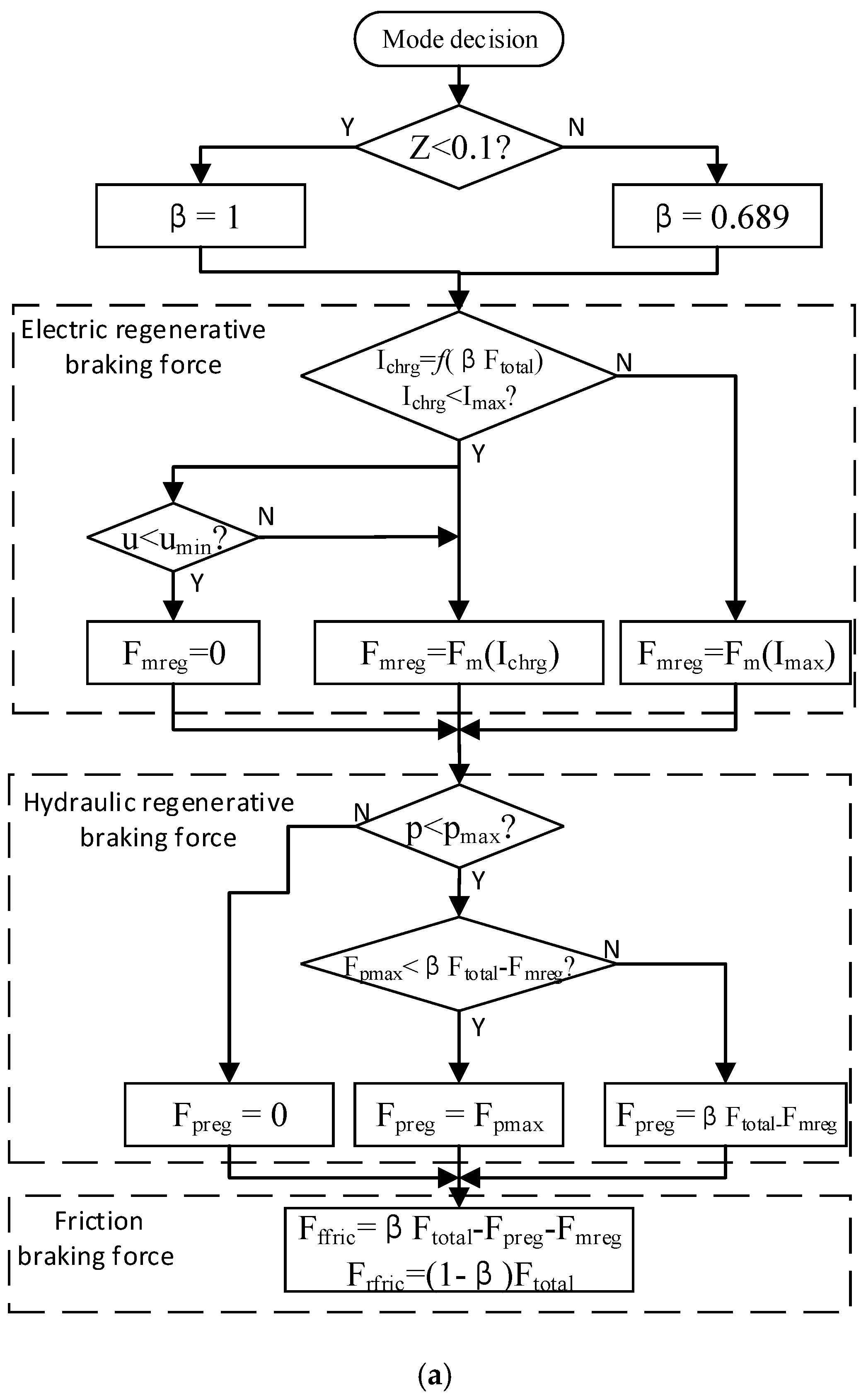
The braking force distribution method following the minimum current impact is illustrated in Figure 4:
- (1)
- According to the braking demand from the driver, the distribution ratio β is designated. When a/g < 0.1 and β = 1, the front wheels alone provide the braking force; when a/g > 0.1 and β = 0.689, the braking force is distributed between the front and rear axles in the ratio β.
- (2)
- According to the braking force required by the front axle, the current required by the electric motor Ichrg is calculated. If Ichrg < Imax, the braking force generated by the motor completely provides the braking force required by the front axle; Fmreg = βFtotal (for example, point A in Figure 4b). If Ichrg > Imax, the braking force generated by the motor is restricted by the current; Fmreg = f(Imax).
- (3)
- When the generated current is restricted, the braking force generated by the electric motor is insufficient. If the hydraulic regenerative braking force could cover the remaining part of the requirement, the insufficient part is provided by the hydraulic system (for example, point B in Figure 5b). Otherwise, the hydraulic system provides its maximum.
- (4)
- If the hydraulic braking force and electric braking force together are insufficient, notwithstanding the hydraulic system providing its maximum, the friction force contributes the insufficient part (for example, point C in Figure 5b).
4.4. ABS Control Strategy
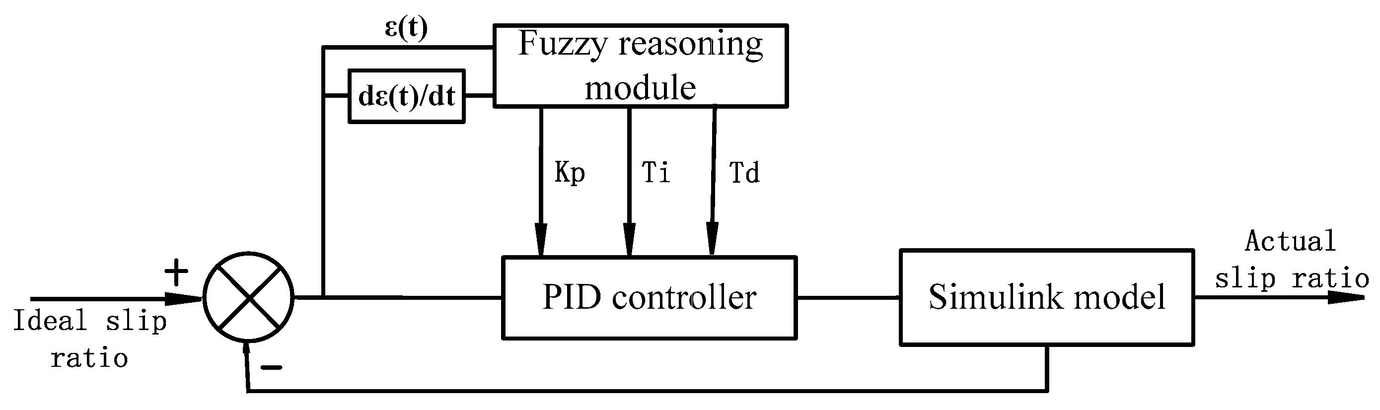
Based on its characteristics of fast response and self-tuning, Fuzzy-PID (Proportional-Integral-Derivative) control strategy is suitable for non-linear systems [16]. Therefore, Fuzzy-PID strategy is used in ABS control. The conventional PID control can be written as:
The structure of the Fuzzy controller is illustrated in Figure 6. In this study, the difference between the ideal slip ratio and the actual slip ratio (E) and its change rate (EC) are selected as input variables. Meanwhile, the proportional coefficient (Tp), integral coefficient (Ti), and differential coefficient (Td) are selected as output variables. A triangle membership function is selected for the input and output variables, with seven values used for each variable; namely, negative big (NB), negative medium (NM), negative small (NS), zero (Z), positive small (PS), positive medium (PM), and positive big (PB) [20].
The regulation of the feature coefficient of the PID controller depends on the system requirements and practical experience. The principles of the FUZZY control in this study are shown in Table 1.
5. Modeling
5.1. Basic Parameters
The parameters of the hydraulic system are based on the dynamic requirements of the vehicle. The fundamental parameters are shown in Table 2.
In the braking process, the gas in the accumulator can be regarded as undergoing an adiabatic process. The volume of the accumulator is to satisfy the requirements for absorbing the average braking energy in a typical driving cycle:
From Equation (6), the volume of the accumulator is to be:
In the braking process, the braking torque generated by the secondary component is to be at least equal to the average braking torque required in a typical driving cycle:
From Equation (4), the displacement of the secondary component is:
From Equations (13) and (15), the model of the accumulator and secondary component can be obtained. The fundamental parameters of the accumulator and secondary component are presented in Table 3.
5.2. Simulation Models
To verify the effectiveness of the control strategy, the simulation models are constructed in AMESim and MATLAB/Simulink platforms.
The hydraulic system model, including the hydraulic regenerative braking system and the friction braking system, was constructed in an AMESim platform, as illustrated in Figure 7. The vehicle powertrain model, which is composed of an electric motor model, battery model, wheel and road model, and the vehicle’s dynamic model, and the control system were constructed in a MATLAB/Simulink platform, as illustrated in Figure 8. The data can be exchanged in real time via an AMESim-Simulink co-simulation interface [21].
6. Simulation Results
6.1. Simulation Results by Following Maximum Energy Recovery Rate
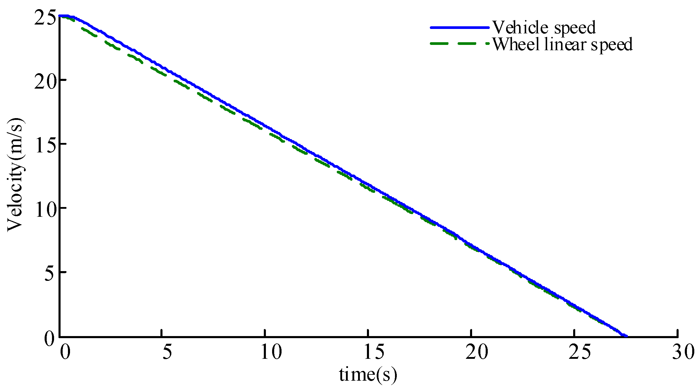
It is assumed that the driver intends to increase the braking strength (z = a/g) from 0 to 0.09 in the first 1 s and then hold the brake pedal until the braking process is completed (see Figure 9). From Section 3, it is known that the vehicle is under low strength braking mode, which implies that the braking force is completely provided by the front wheels.
Figure 10 and Figure 11 illustrate the comparison between the vehicle speed, the wheel linear speed, and the deceleration of the vehicle. From the figures, it can be determined that the wheel linear speed follows the vehicle’s velocity, and the deceleration of the vehicle is approximately steady, with fluctuation appearing only during the braking-mode switch process. The violent fluctuation at the end is mainly caused by numerical error.
Figure 12 illustrates the distribution of various braking forces and their variation. When the braking begins, the hydraulic braking provides the demanded braking force. Then, the electric braking is activated. The sum of the hydraulic braking force and electric braking force equals the total demanded braking force. As the braking process continues, when the pressure of the hydraulic accumulator is about to attain its maximum (approximately in time t = 17 s), the hydraulic braking force decreases, and the electric braking force increases. After the hydraulic braking system ceases braking, the electric braking provides the complete braking force. At the end of the braking process, the velocity is too low to generate feedback current; then, friction braking is activated to stop the vehicle.
The distribution of the various braking forces illustrates that the regenerative braking force provided almost the complete braking energy. As calculated from the simulation results, during the whole braking process, the hydraulic energy recovery rate is 43.4%, while the electric energy recovery rate is 50.8%. The total recovery rate is 94.2%.
6.2. Simulation Results by Following Minimum Current Impact
Due to the restriction by the charge current, the electric motor could not provide the required braking force in the initial stage of the braking process. Therefore, both friction and hydraulic braking are required to feed the insufficient part. Figure 13 illustrates the distribution of various braking forces and their variation based on the minimum current impact principle. As depicted in the figure, at the beginning of the braking process, all the three braking forces are activated; first, electric braking, next, hydraulic braking, and finally, friction braking. As the electric braking force and hydraulic braking force increase and the demanded braking force remains unaltered, the friction braking force decreases gradually until the regenerative braking force (electric + hydraulic) is adequate to satisfy the braking requirement. To steadily maintain the charge current, the hydraulic braking force declined at time t = 13 s. At the end of the braking process, the braking force is also provided by friction, as the motor is not capable of generating feedback current.
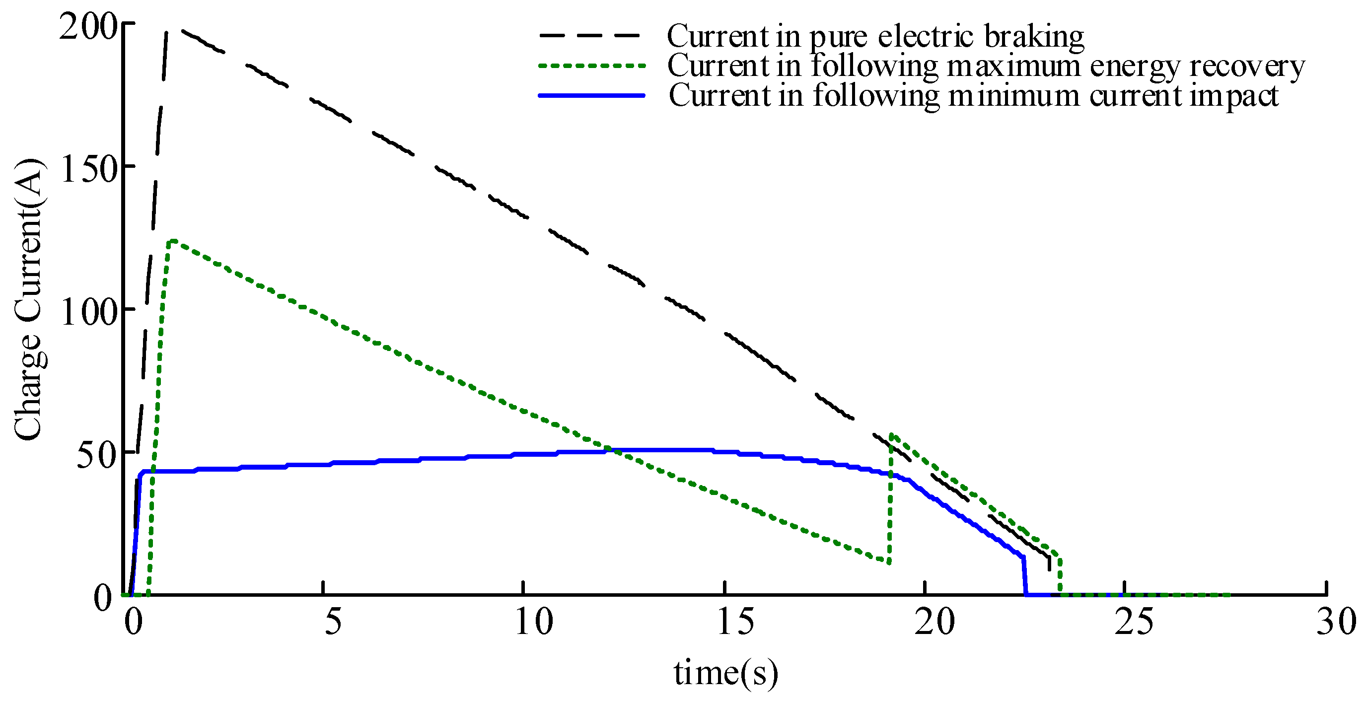
Figure 14 illustrates the charge currents in various braking force distribution principles compared with the charge current in pure electric braking (without any hydraulic system). As illustrated in Figure 13, in pure electric braking, the instantaneous charge current reaches as high as 200 A. Under the maximum energy recovery rate principle, although the charge current has declined significantly, the charge current is substantially high (120 A). More critically, in the braking process, the current fluctuates when the system switches between the braking forces. By following the minimum current impact principle, the charge current is held under 50 A without fluctuation.
Based on the simulation results, the energy recovery rates of the hydraulic system and the electric system were calculated and compared to the results of the maximum energy recovery rate, which are presented in Table 4. According to the results, due to the restriction of the charge current, the electric motor could not exert its maximum power. The energy recovery rate is 38.9%, which is lower than that attained by following the maximum energy recovery rate principle.
6.3. Changing Deceleration and ABS Response
In the case of braking with high braking deceleration intent, the slip ratio of the wheel may exceed its limitation; then, the ABS is triggered. Therefore, it is necessary to study the mechanism of coordination between the ABS and regenerative braking.
Assume that the driver intends to increase the braking strength (z = a/g) from 0 to 0.5 in the first second and then hold the brake pedal for 2 s. Subsequently, the driver intends to increase the braking strength to 0.9 in 1 s, then hold the brake pedal until the vehicle stops (Figure 15).
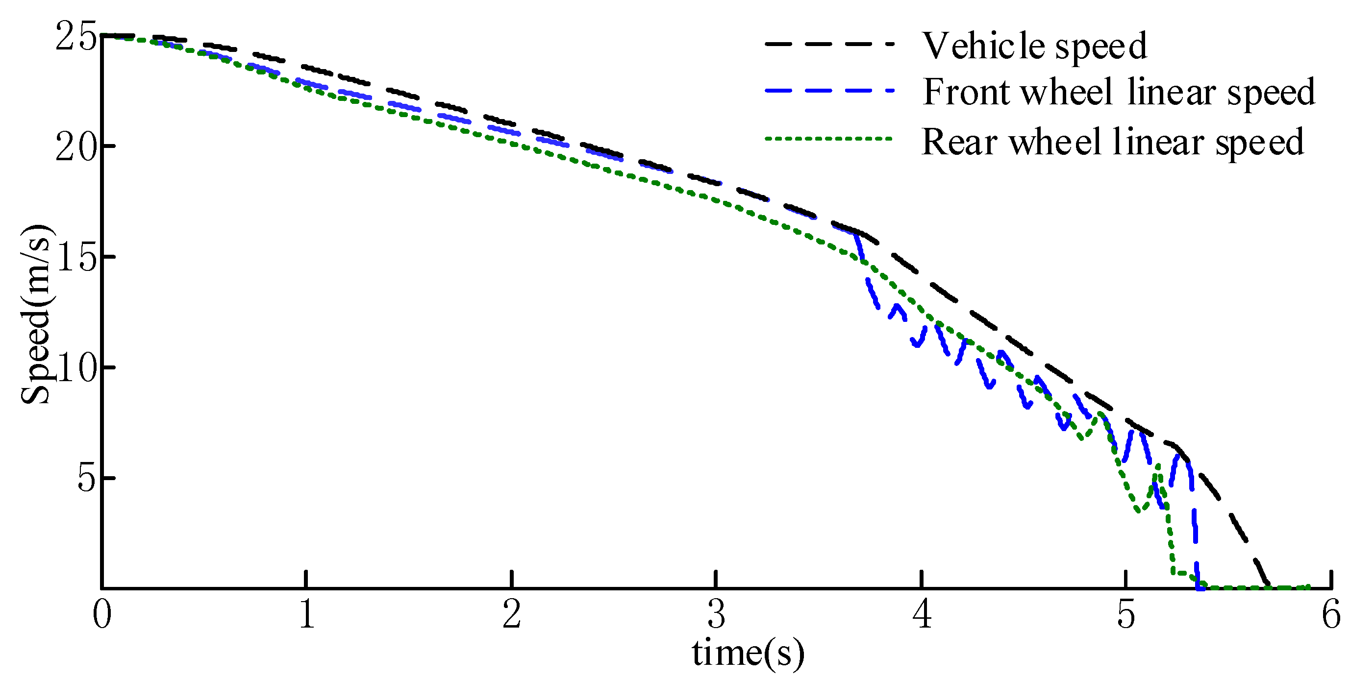
Figure 16, Figure 17 and Figure 18 depict the speed comparison, deceleration of the vehicle, and slip ratio of the wheels. Before time t = 3.7 s, as the demanded braking force is lower than the adhesion force on the ground, the wheel linear speed follows the vehicle speed; the deceleration remains stable, and the slip ratio is approximately zero. After time t = 3.7 s, as the demanded braking force increases, the adhesion force fails to provide the demanded braking force. The high slip ratio triggers the ABS. In this phase, the wheel speed fluctuates. However, it can still follow the vehicle speed; moreover, the deceleration of the wheel fluctuates rapidly. The wheel slip ratio is regulated around an optimal value by ABS.
The distribution of the various braking torques of the front wheel is illustrated in Figure 19. Before time t = 3.7 s, the braking force is completely provided by regenerative braking (including hydraulic braking and electric braking). When the ABS is triggered, the entire regenerative braking system stops, and the function of the ABS is completed by the friction braking system.
7. Summary
- (1)
- By incorporating a hydraulic energy storage system into a pure electric prototype, a novel electro-hydraulic hybrid system was designed. This system is aimed at absorbing high power braking energy as well as suppressing the impact of current on the battery.
- (2)
- The simulation models of the components in the powertrain are constructed to form a combined simulation model. Two control strategies, which are based on two separate rules, the maximum energy recovery rate and the minimum charge current impact, are designed and compared. The simulation results indicated the effectiveness of the two strategies; the energy recovery rate is higher when the principle of the maximum energy recovery rate is followed. The charging current is gentle and without fluctuation when the principle of minimum current impact is followed, although the energy recovery rate is lower.
- (3)
- The ABS control strategy is simulated with variable braking deceleration intent. The result demonstrates that the ABS is triggered as soon as the slip ratio crosses the threshold; the wheel slip ratio can then be regulated to around the optimal value to ensure braking safety.
Acknowledgments
The research is supported by: (1) the National Natural Science Foundation of China (51575063), (2) the Chongqing Significant Application and Development Planning Project (cstc2015yykfC60003). The authors would also like to acknowledge the support from the State Key Laboratory of Mechanical Transmission of Chongqing University, China. The authors are indebted to the people who have helped to improve the paper.
Author Contributions
Yang Yang designed the electric-hydraulic system and proposed the control strategies; Chang Luo conducted model building, calculation and analysis based on proposed control strategies; Pengxi Li matched the parameters of the electric-hydraulic system and analyzed system performance.
Conflicts of Interest
The authors declare no conflict of interest.
References
- Borba, B.S.M.C.; Szklo, A.; Schaeffer, R. Plug-in hybrid electric vehicles as a way to maximize the integration of variable renewable energy in power systems: The case of wind generation in northeastern Brazil. Energy 2012, 37, 469–481. [Google Scholar] [CrossRef]
- Lu, L.; Han, X.; Li, J.; Hua, J.; Ouyang, M. A review on the key issues for lithium-ion battery management in electric vehicles. J. Power Sources 2013, 226, 272–288. [Google Scholar] [CrossRef]
- Onda, K.; Ohshima, T.; Nakayama, M. Thermal behavior of small lithium-ion battery during rapid charge and discharge cycles. J. Power Sources 2006, 158, 535–542. [Google Scholar] [CrossRef]
- Schaltz, E.; Khaligh, A.; Rasmussen, P.O. Investigation of battery/ultracapacitor energy storage rating for a fuel cell hybrid electric vehicle. In Proceedings of the IEEE Vehicle Power and Propulsion Conference, Harbin, China, 3–5 September 2008; pp. 1–6. [Google Scholar]
- Wu, Y.; Jiang, X.; Xie, J. The reasons of rapid decline in cycle life of Li-ion battery. Batter. Bimon. 2009, 4, 80–82. [Google Scholar]
- Wang, B.; Zhang, J.; Luo, Y. A study on regenerative braking for parallel hybird electric bus. Automot. Eng. 2005, 27, 649–651. [Google Scholar]
- Amjad, S.; Rudramoorthy, R.; Neelakrishnan, S.; Varmana, K.S.R.; Arjunan, T.V. Evaluation of energy requirements for all-electric range of plug-in hybrid electric two-wheeler. Energy 2011, 36, 1623–1629. [Google Scholar] [CrossRef]
- Niu, G.; Shang, F.; Krishnamurthy, M.; Garcia, J.M. Evaluation and selection of accumulator size in electric-hydraulic hybrid (EH2) powertrain. In Proceedings of the IEEE Transportation Electrification Conference and Expo (ITEC), Dearborn, MI, USA, 27–29 June 2016; pp. 1–6. [Google Scholar]
- World’s First Full Hydraulic Hybrid SUV Presented at 2004 SAE World Congress. United States Environmental Protection Agency: Washington, DC, USA, 2004. Available online: https://permanent.access.gpo.gov/gpo60682/P1001T88.PDF (accessed on 11 July 2017).
- PSA Group. Hybrid Air: An Innovative Full-Hybrid Petrol Solution for the Car of the Future. Available online: https://www.groupe-psa.com/en/newsroom/automotive-innovation/hybrid-air/ (accessed on 11 July 2017).
- Luo, C.; Yang, Y.; Li, P. Design and Parameter Matching of a New Electro hydraulic Hybrid Transmission System. In Proceedings of the International Conference on Motion and Power Transmissions, Kyoto, Japan, 1–3 March 2017. [Google Scholar]
- Li, J. Modeling and Simulation on Regenerative Braking System of Hydraulic Hybrid Vehicle Based on AMESim-Simulink. Master’s Thesis, Chongqing University, Chongqing, China, 2013. [Google Scholar]
- Chen, H.; Yuan, S. Design of Hydraulic System for Braking Energy Recovery of Urban Vehicle. Hydraul. Pneum. 2003, 49, 1–3. [Google Scholar]
- Takahiro, N.; Setsuko, K.; Hirobumi, A. Development of a New Regenerative Braking System; SAE International: Warrendale, PA, USA, 2013. [Google Scholar]
- Regulation No 13 of the Economic Commission for Europe of the United Nations (UN/ECE)—Uniform Provisions Concerning the Approval of Vehicles of Categories M, N and O with Regard to Braking [2016/194]. Available online: http://eur-lex.europa.eu/legal-content/EN/TXT/?uri=CELEX:42016X0218(01) (accessed on 11 July 2017).
- Yang, Y. New Electro-hydraulic Braking System for Pure Electric Vehicle. Master’s Thesis, Chongqing University, Chongqing, China, 2012. [Google Scholar]
- Jiang, X. Study on Battery Management System of Lithium-Ion Batteries. Ph.D. Thesis, Graduate University of Chinese Academy of Sciences, Shanghai, China, 2007. [Google Scholar]
- Gao, Y.; Mehrdad, E. Electronic Braking System of EV and HEV—Integration of Regenerative Braking Automatic Braking Force Control and ABS; SAE International: Warrendale, PA, USA, 2001. [Google Scholar]
- Tawadros, P.; Zhang, N. Integration and performance of regenerative braking and energy recovery technologies in vehicles. In Alternative Fuels and Advanced Vehicle Technologies for Improved Enviromental Performance: Towards Zero Carbon Transportation; Woodhead Publishing: Cambridge, UK, 2014; pp. 541–563. [Google Scholar]
- Ko, J.W.; KO, S.Y.; Kim, I.S.; Hyun, D.Y.; Kim, H.S. Co-operative Control for Regenerative Braking and Friction Braking to Increase Energy Recovery without Wheel Lock. Int. J. Automot. Technol. 2014, 15, 253–262. [Google Scholar] [CrossRef]
- Lynn, A.; Smid, E.; Eshraghi, M.; Caldwell, N.; Woody, D. Modeling Hydraulic Regenerative Hybrid Vehicles Using AMESim and Matlab/Simulink. Proc. SPIE 2005, 5805. [Google Scholar] [CrossRef]
Figure 1.
Structure and character of hydraulic hybrid system. (a) Energy flow of Eaton Hydraulic hybrid system; (b) Structure of PSA ‘Hybrid Air’ system.
Figure 1.
Structure and character of hydraulic hybrid system. (a) Energy flow of Eaton Hydraulic hybrid system; (b) Structure of PSA ‘Hybrid Air’ system.

Figure 2.
Structure of the hydraulic circuit. (1,4) Two-position two-way valve; (2,5) Cartridge valve; (3) One way valve.
Figure 2.
Structure of the hydraulic circuit. (1,4) Two-position two-way valve; (2,5) Cartridge valve; (3) One way valve.

Figure 3.
Braking modes. (Ff) Braking force in the front axle; (Fr) braking force in the rear axle; (φ) the attachment coefficient; (I) the ideal braking force distribution curve.
Figure 3.
Braking modes. (Ff) Braking force in the front axle; (Fr) braking force in the rear axle; (φ) the attachment coefficient; (I) the ideal braking force distribution curve.

Figure 4.
Braking force distribution strategy by following the maximum energy recovery rate. (a) Braking force distribution strategy flow chart; (b) Braking force distribution curve.
Figure 4.
Braking force distribution strategy by following the maximum energy recovery rate. (a) Braking force distribution strategy flow chart; (b) Braking force distribution curve.

Figure 5.
Braking force distribution by following the minimum current impact. (a) Braking force distribution strategy flow chart; (b) Braking force distribution curve.
Figure 5.
Braking force distribution by following the minimum current impact. (a) Braking force distribution strategy flow chart; (b) Braking force distribution curve.


Figure 6.
Structure of Fuzzy Control System.

Figure 7.
Hydraulic system model constructed on AMESim.

Figure 8.
Vehicle components and control system model on Simulink.

Figure 9.
Brake intent from the driver.

Figure 10.
Vehicle speed and wheel linear speed.

Figure 11.
Vehicle braking deceleration curve.

Figure 12.
Brake torque distribution and its variation in the front axle.

Figure 13.
Braking torque distributions and their distribution in the front axle.

Figure 14.
Vehicle braking deceleration curve.

Figure 15.
Brake intent variation.

Figure 16.
Vehicle speed and wheel speed.

Figure 17.
Vehicle and wheel deceleration.

Figure 18.
Slip ratio variation.

Figure 19.
Brake torque distributions and their variation in the front axle.


Table 1.
Fuzzy logic control rules.
| Judgement Conditions | Results |
|---|---|
| (1) if (E is NB) and (EC is NB) | then (Kp is PB), (Ti is N), (Td is PS) |
| (2) if (E is NB) and (EC is NM) | then (Kp is PB), (Ti is N), (Td is NS) |
| (3) if (E is NB) and (EC is NS) | then (Kp is PM), (Ti is N), (Td is NB) |
| (4) if (E is NB) and (EC is Z) | then (Kp is PM), (Ti is N), (Td is NB) |
| (5) if (E is NB) and (EC is PS) | then (Kp is PS), (Ti is N), (Td is NB) |
| (6) if (E is NB) and (EC is PM) | then (Kp is Z), (Ti is Z), (Td is NM) |
| (7) if (E is NB) and (EC is PB) | then (Kp is Z), (Ti is Z), (Td is PS) |
| ▪ ▪ ▪ ▪ ▪ ▪ | ▪ ▪ ▪ ▪ ▪ ▪ |
| (43) if (E is PB) and (EC is NB) | then (Kp is Z), (Ti is Z), (Td is PB) |
| (44) if (E is PB) and (EC is NM) | then (Kp is Z), (Ti is Z), (Td is PM) |
| (45) if (E is PB) and (EC is NS) | then (Kp is NM), (Ti is NM), (Td is PM) |
| (46) if (E is PB) and (EC is Z) | then (Kp is NM), (Ti is PM), (Td is PM) |
| (47) if (E is PB) and (EC is PS) | then (Kp is NM), (Ti is PM), (Td is PS) |
| (48) if (E is PB) and (EC is PM) | then (Kp is NB), (Ti is PB), (Td is PS) |
| (49) if (E is PB) and (EC is PB) | then (Kp is N), (Ti is PB), (Td is PB) |
Notes: NB—Negative Big, NM—Negative Medium, NS—Negative Small, Z—Zero, PS—positive small, PM—Positive Medium, PB—positive big.
Table 2.
Basic Parameters of the Power Transmission System
| Components | Parameters | Value |
|---|---|---|
| Basic parameters of the vehicle | Loaded mass (m) | 1825 kg |
| Wheel rolling radius (r) | 0.308 m | |
| Wheelbase (L) | 2.28 m | |
| Distance from front axle to mass center (L1) | 1.25 m | |
| Height of the mass center (hg) | 0.585 m | |
| Motor | Rated power (Pr) (kw) | 35 kw |
| Rated rotational speed (nr) | 3000 rpm | |
| Rated torque (Tr) | 111.4 Nm | |
| Battery | Rated voltage (U) | 336 V |
| Capacity | 70 Ah |
Table 3.
Fundamental parameters of the hydraulic system.
| Components | Parameters | Value |
|---|---|---|
| Pump/motor (secondary component) | Maximum displacement (Vp/m max) | 18 cm3 |
| Maximum rotational speed (np/m max) | 3300 rpm | |
| Peak power (Pp/m max) | 30 kw | |
| Peak torque (Tp/m max) | 80 Nm | |
| Accumulator | Volume (Va) | 10 L |
| Working pressure (Pa) | 330 Bar |
Table 4.
Simulation results of various braking modes.
| Braking Force Distribution Principle | Energy Recovery Rate of Hydraulic System | Energy Recovery Rate of Electric System | Total Energy Recovery Rate |
|---|---|---|---|
| Maximum energy recovery rate | 43.4% | 50.8% | 94.2% |
| Minimum current impact | 37.6% | 38.9% | 76.5% |
© 2017 by the authors. Licensee MDPI, Basel, Switzerland. This article is an open access article distributed under the terms and conditions of the Creative Commons Attribution (CC BY) license (http://creativecommons.org/licenses/by/4.0/).
Share and Cite
MDPI and ACS Style
Yang, Y.; Luo, C.; Li, P. Regenerative Braking Control Strategy of Electric-Hydraulic Hybrid (EHH) Vehicle. Energies 2017, 10, 1038. https://doi.org/10.3390/en10071038
AMA Style
Yang Y, Luo C, Li P. Regenerative Braking Control Strategy of Electric-Hydraulic Hybrid (EHH) Vehicle. Energies. 2017; 10(7):1038. https://doi.org/10.3390/en10071038
Chicago/Turabian StyleYang, Yang, Chang Luo, and Pengxi Li. 2017. "Regenerative Braking Control Strategy of Electric-Hydraulic Hybrid (EHH) Vehicle" Energies 10, no. 7: 1038. https://doi.org/10.3390/en10071038
Note that from the first issue of 2016, this journal uses article numbers instead of page numbers. See further details here.