Article

Investigation of the Energy Performance of a Novel Modular Solar Building Envelope

1
School of Architecture, Heilongjiang Cold Climate Architectural Science Key Laboratory, Harbin Institute of Technology, 66 Xidazhi Street, Harbin 150001, China
2
School of Engineering and Computer Science, University of Hull, Hull HU178XH, UK
3
Heilongjiang Environmental Monitoring Center Station, Harbin 150056, China
*
Authors to whom correspondence should be addressed.
Energies 2017, 10(7), 880; https://doi.org/10.3390/en10070880
Submission received: 25 May 2017 / Revised: 22 June 2017 / Accepted: 26 June 2017 / Published: 30 June 2017
(This article belongs to the Special Issue Solar Technologies for Buildings)

Abstract

:
The major challenges for the integration of solar collecting devices into a building envelope are related to the poor aesthetic view of the appearance of buildings in addition to the low efficiency in collection, transportation, and utilization of the solar thermal and electrical energy. To tackle these challenges, a novel design for the integration of solar collecting elements into the building envelope was proposed and discussed. This involves the dedicated modular and multiple-layer combination of the building shielding, insulation, and solar collecting elements. On the basis of the proposed modular structure, the energy performance of the solar envelope was investigated by using the Energy-Plus software. It was found that the solar thermal efficiency of the modular envelope is in the range of 41.78–59.47%, while its electrical efficiency is around 3.51% higher than the envelopes having photovoltaic (PV) alone. The modular solar envelope can increase thermal efficiency by around 8.49% and the electrical efficiency by around 0.31%, compared to the traditional solar photovoltaic/thermal (PV/T) envelopes. Thus, we have created a new envelope solution with enhanced solar efficiency and an improved aesthetic view of the entire building.

1. Introduction

According to the statistics, the building sector accounts for approximately 40% [1] of the primary energy consumption and 32% [2] of total carbon emission. Thus, effective utilization of the locally available renewable energy sources is regarded as an important measure to reduce fossil fuel consumption in buildings and cut associated carbon emission. The combination of solar collecting elements and building envelope has been proposed and implemented for a few decades. In the early stage, some people believed that the main purpose of the so-called solar energy and building-integrated design was to optimize the solar photovoltaic and thermal components to meet the requirements of the construction industry and the overall aesthetic requirement [3]. This opinion reflects the existing problems between solar energy and architecture design at that time. However, further integration requires more sophisticated designs based on the unique features of solar energy, which are outlined as follows. Firstly, the orientation and obliquity of a device can affect its utility of solar energy [4]. Secondly, the combination of solar energy and architecture is a comprehensive technology that requires the cooperation of different professionals, such as civil engineering, architecture design, and electrical engineering.
An important way to reduce building energy consumption is to improve the construction speed, quality, and efficiency of the building. To achieve this goal, reducing construction costs and increasing the construction (or transformation) speed is the priority. At the same time, the improvement of the construction (or transformation) efficiency cannot be separated from the development, demonstration, and replication of the solution proposal. The prefabrication of building components is a common and effective method to solve the above problems. Compared with the traditional construction technology, prefabricated components that are normally manufactured in factories can effectively reduce the construction cost and improve the construction efficiency without affecting the quality of the installation, demolition, and reuse of building materials.
In recent years, modular solar epidermal (wall/roof) structures have been widely discussed, with many studies and patents turning to this area. Patents, materials, and products related to this field mainly include the following two aspects: a modular system based on solar thermal energy utilization and a solar photovoltaic/thermal-based modular system.

1.1. Modular System Based on Solar Thermal Collector

In recent years, the research and case study of solar thermal energy and building envelopes have been developed to a certain extent. Most of the solar collectors (glazed flat plate or evacuated tubes) used in solar thermal systems are not part of the building facade and are usually installed on roofs for layout convenience. Apart from the roof-based solar collectors, there are also facade-based solar collectors [5,6,7,8]. They make use of the building envelope for solar energy collection to produce thermal energy, providing an efficient way of reducing building energy consumption [9,10]. These devices have easy assembly and disassembly owing to their modular structure and two-points-coupling connection, thus leading to the improved building aesthetics. However, these devices are still not “truly” integrated with the building facade. Instead, they are simply hung on the facade walls, as shown in Table 1. Therefore, the cost of the system is high, and most importantly, the installation detracts from the aesthetic view of the building.

1.2. Modular System Based on Solar Photovoltaic/Thermal Collector

As an effective way to utilize solar energy, the solar photovoltaic/thermal integrated module has gained widespread attention. Although the research and development of the photovoltaic/thermal technology began in the 1970s [11,12], the combination of the PV/T and architecture appeared much later [13]. The solar photovoltaic/thermal integrated module uses its surface to efficiently absorb solar radiation to generate electricity and heat. The Englert solar module system is a typical example, as shown in Table 2. Combined with the solar photovoltaic/thermal integrated module, it can be installed in a solid and suitable way and create an integrated metal roof that is combined with the building. This structure can save energy and reduce carbon emissions by 20–80%. Fujisawa and Tani [14] compared the performance of a hybrid PV/T system and a unit of separate PV and thermal systems covering the same area on the basis of exergy efficiency. They found that the hybrid design achieved higher exergy output. Each of the studies of roof-integrated PV/T systems arrived at similar conclusions [15,16,17]. Some photovoltaic/thermal integrated modules are also combined with phase change materials such as gypsum thermal core plate, which can stabilize the module's energy output and extend the energy supply time.

1.3. Summary of Deficiencies in Existence

The availability of the above-listed solid facades has created a considerable energy-saving potential and is therefore expected to have a good market perspective. However, these technologies have also been identified with several inherent problems that may become barriers in future market penetration. The common problems are due to (1) complex structures containing multiple heat absorbing plates (pipes) and heat exchanging units; (2) relatively low solar efficiencies owing to less-effective heat absorption of the water pipes (or air ducts) and less-efficient heat transfer between one layer and another; as well as (3) a larger heat loss to surroundings when the operational temperature is higher, owing to the failure in the use of heat pipes. As a result, a larger facade area and a higher system cost have become the obvious disadvantages of the existing devices. In line with these difficulties, developing a highly efficient, simply structured, prefabricating-enabled, easily assembled/maintained/repaired, low-cost and aesthetically attractive solar building envelope that has either (both) thermal insulation or (and) solar heat and/or electricity generation functions in addition to being appropriate for building renovations is urgently needed. This is required in order to create a technical breakthrough in this area and subsequently promote wide and fast market development.

2. Concept and Approach

The proposed research aims to design a more convenient, secure, and suitable installation solar building envelope module. When jointly operated with the building services systems, this is expected to harness several prominent technical and economic merits: (1) enhanced solar photovoltaic efficiency owing to the microchannel heat collector configuration that allows enhanced heat and efficiency between the collector fluid and passing water, which thus reduced the required area of the solar building envelope and smaller number of microchannel heat collectors within each solar building envelope module; (2) easy assembly and disassembly owing to its modular structure and two-points-coupling connection; (3) wide adaptability to both retrofitting and new builds; (4) great flexibility in utilization for heating, cooling, ventilation, and hot water generation in buildings; and (5) appealing aesthetic effect in terms of the shape, color, size, and architectural integration. These innovations would capture the opportunity to remove the critical barriers remaining with the practical solar facade application in buildings (e.g., poor solar fraction in collecting and utilizing solar heat, difficult operation in assembly and disassembly, limited function for use in building services, and unpleasant aesthetic view). By delivering an effective solar building envelope module that can be integrated as well as an aesthetically appealing solar collecting module, the research will greatly promote development of renewable (solar) driven, distributed (or centralized) heating and cooling at the building, district, and city scales which would lead to significant savings in fossil fuel consumption and reductions in carbon emission.

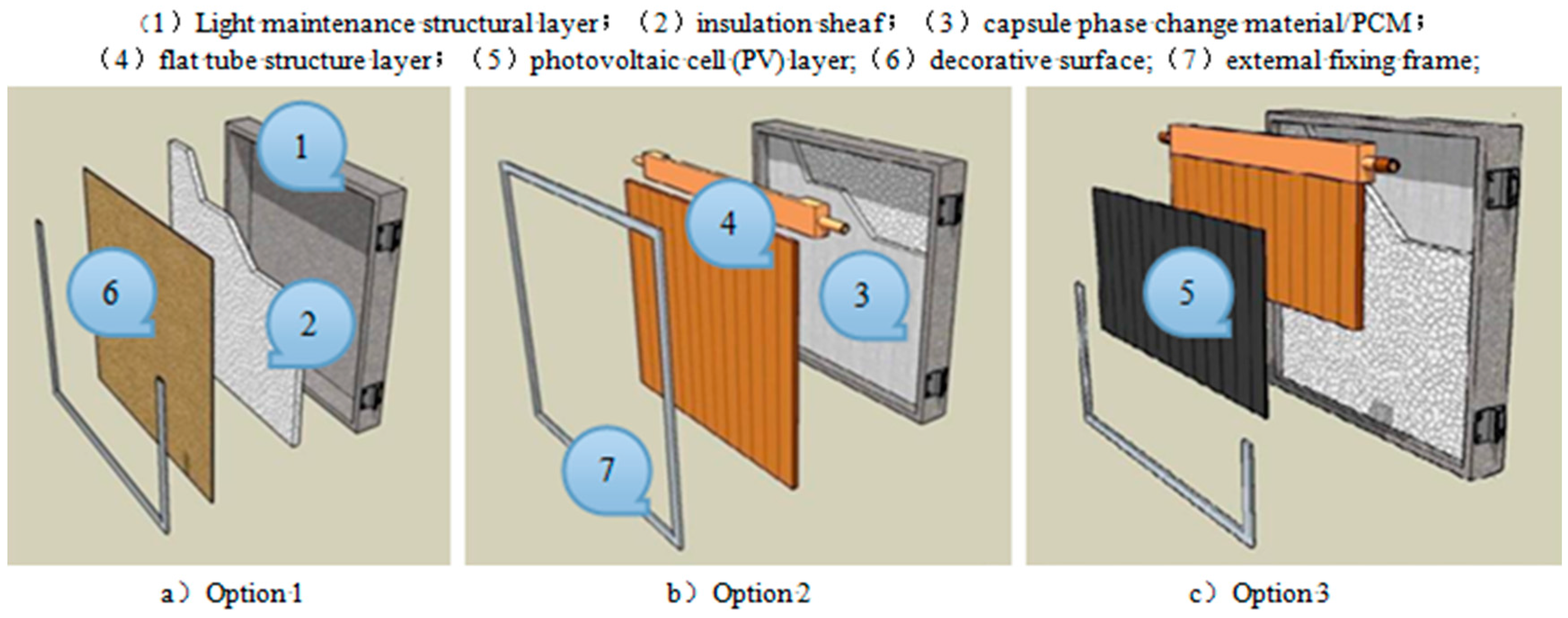
2.1. Concepts of the Design

The proposed new cladding is an unglazed multiple-layer module consisting of two basic elements: a light-weight supporting enclosure and an insulation layer, as shown in Figure 1a. It may contain two additional elements to enable the collection of solar heat: a micro-encapsulated phase-change material (PCM) layer and a micro-channel flat tube panel, as shown in Figure 1b. If solar electricity generation is needed, the module could also incorporate a layer of PV cells layer that is attached onto the micro-channel flat tube panel, as shown in Figure 1c. For each of these three options, an external fixing-up frame is needed. For the configuration shown in Figure 1a, an external decorative layer should also be incorporated.
In the tropical regions of China, if the module is to be installed in the directions of north-, east-, or west-facing directions where solar radiation significantly varies with time, the collection of solar heat and power appears to be insignificant due to insufficient solar resources and relatively expensive solar collecting panels. In this situation, the basic structure comprising the supporting enclosure and insulation layer, named “Option 1”, may be a good choice, and is shown schematically in Figure 1a.
If the module is to be installed in the south-facing wall, where solar radiation is high, the PCM layer micro-channel flat tube panel might be beneficial if integrated to enable collection of the solar heat. However, the installation of PVs may be unnecessary due to the unfavorable inclination angle and the relatively high cost of the PVs. This structure, named “Option 2”, is shown schematically in Figure 1b.
If the module is to be installed on a south-facing roof where the solar radiation is significantly intensive and the solar incident direction is almost normal to the roof surface, it would be beneficial to integrate PVs into the structure, as these would generate higher volumes of electricity than on other surfaces. The installation of the PVs could involve simply spanning these over the full (or part) range of the heat pipe panel surface. This structure, named “Option 3”, is shown schematically in Figure 1c.
In addition to the flat-plate design, the new claddings could also be made into curved or even waved shapes to give a different appearance. Their front surfaces could be coated with different solar absorbing materials with varying colors and brightness. These variations will greatly enhance the aesthetic effect of buildings, thus meeting a diverse range of architectural and aesthetic needs.

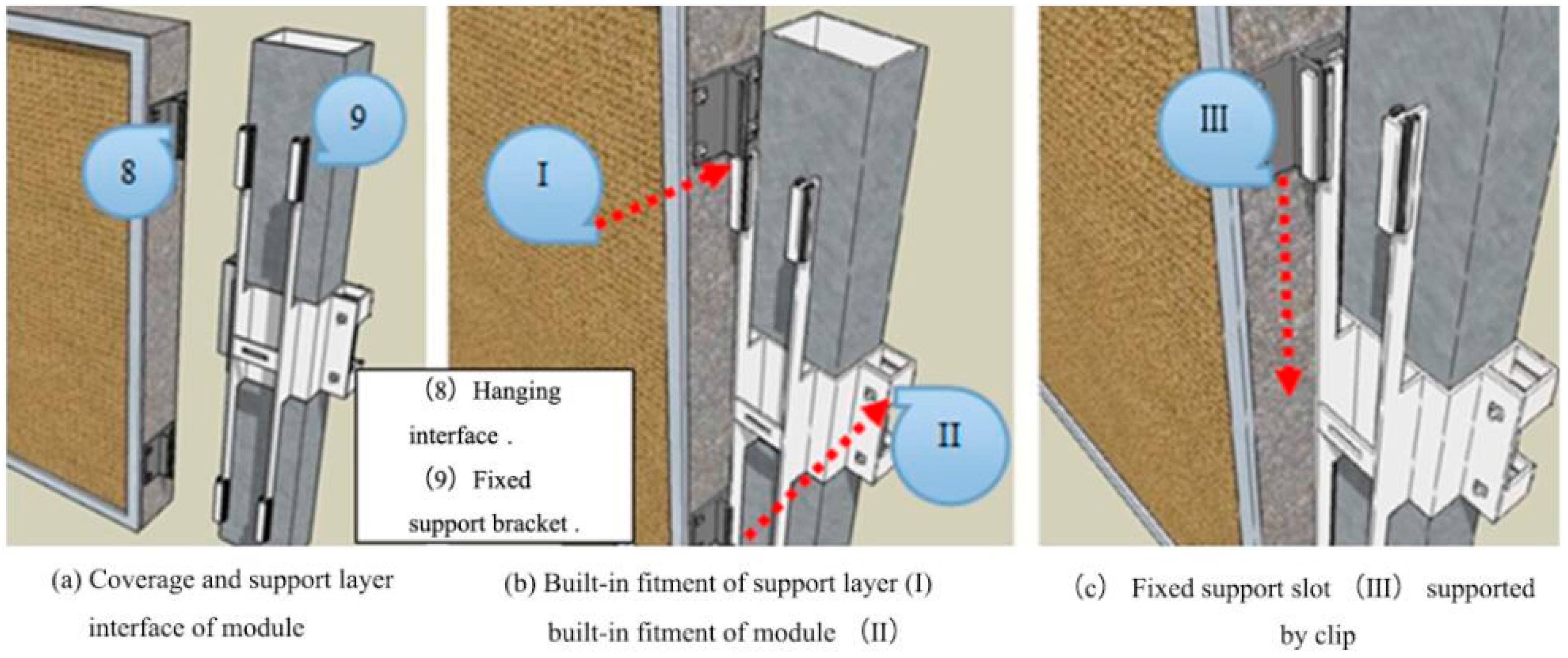
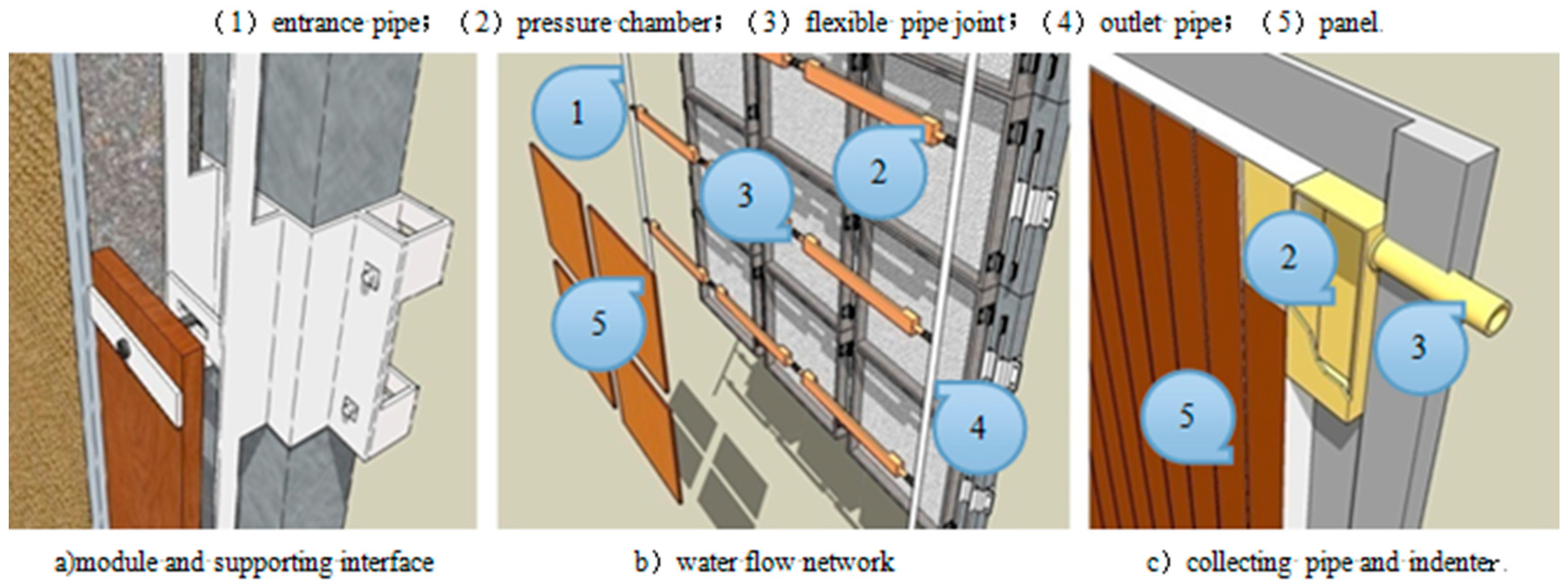
2.2. Information of the Components

Regarding the supporting enclosure, the physical characteristics of the maintenance structure depend on its structure, hierarchy, and material characteristics. Among these, the choice of materials is a basic problem. In addition to the existing aluminum alloy shell, the Harbin Institute of Technology has recently developed a new synthetic resin composed of waste paper and resin with the function of sound insulation, moisture-proofing, and fire resistance. Its density is about 1.2 g/cm3, which is 50% lighter than the conventional aluminum alloy material. Furthermore, the cost of new material is only 75% of the aluminum alloy material, making it especially suitable for industrial transformation and energy-saving prefabricated lightweight construction.
For the thin layer of micro-encapsulated PCM particles, the phase change material (PCM) is a new form of energy storage material that transforms energy by the change between liquid and solid states. Energy is stored when the temperature is above its transition temperature, while energy is released when it is under this temperature [18]. In practical applications, the phase change material should be located on the insulating layer, which can increase the storage capacity of the solar module. Due to the increase in the solar radiation intensity, when the temperature of PCM reaches the phase transition temperature (e.g., 80 °C), the closed PCM particles will be partly melted by absorbing some of the spatial heat. On the contrary, if the solar radiation intensity is weak or the outer space temperature has dropped to a certain extent (such as 70 °C or less), the PCM particles within the stored heat will be transferred to the micro-channel at the top of the flat tube structure layer. As a result, the PCM particles are gradually “frozen”, and thus the service period of the solar system is prolonged. In addition, the PCM has a low cost, good compatibility with the construction materials, as well as good safety and fire resistance.
For the micro-channel flat tube panel, a flat plate solar collector is one of the best choices for the combination of solar energy and architecture. It has many advantages, such as low cost, strong bearing capacity, large heat absorption area, lower heat flux, and reliable operation. However, the heat collection efficiency is only 50% to 60% of that of the vacuum tube collector. Therefore, how to improve the heat collecting efficiency has become a hot research topic. The micro-channel flat tube panel structure has the characteristics of compact structure, light volume, and high heat transfer characteristics [19]. Under the same conditions, a smaller collector diameter and lower heat absorbing plate average temperature results in less heat loss and a higher heat efficiency. When heating the same volume of water, the micro-channel structure takes less time and has higher instantaneous heat collection efficiency. The average heat collecting efficiency is 9.3% higher than the flat plate collector with the best tube spacing, in addition to being 20.6% and 30.6% higher than the two most common collectors, respectively [20]. The former description provides references for its application.
In terms of the PV cells, based on the current technology, temperature is one of the most important factors that affects the conversion efficiency of solar cells. In order to improve the utilization efficiency of solar energy, PV cells could be configured with suitable sizes and attached to the flat-plate micro-channel heat pipe panel using a dedicated lamination technology. In particular, the hybrid system combined with the building can achieve more efficient use of energy, so it has more research and utilization value [21].
For the insulation layer, in a typical flat plate solar collector, the micro-channel flat tube structure dissipates heat to the surrounding environment after heat absorption. One of the measures to reduce the heat loss is to install an insulation layer with certain thickness between the outer frame and the tube plate layer, which can effectively restrain the heat transfer, reduce the heat loss, and improve the efficiency of light and heat conversion. There are a considerable number of thermal insulation materials, such as polyurethane, mineral wool, extruded polystyrene, expanded polystyrene, aero-gels, vacuum panels, etc.

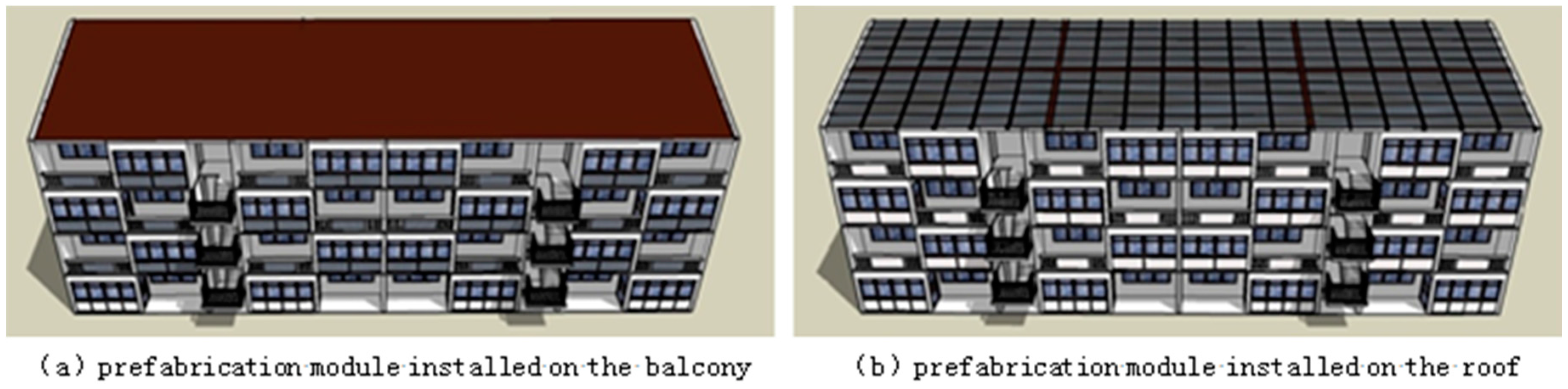
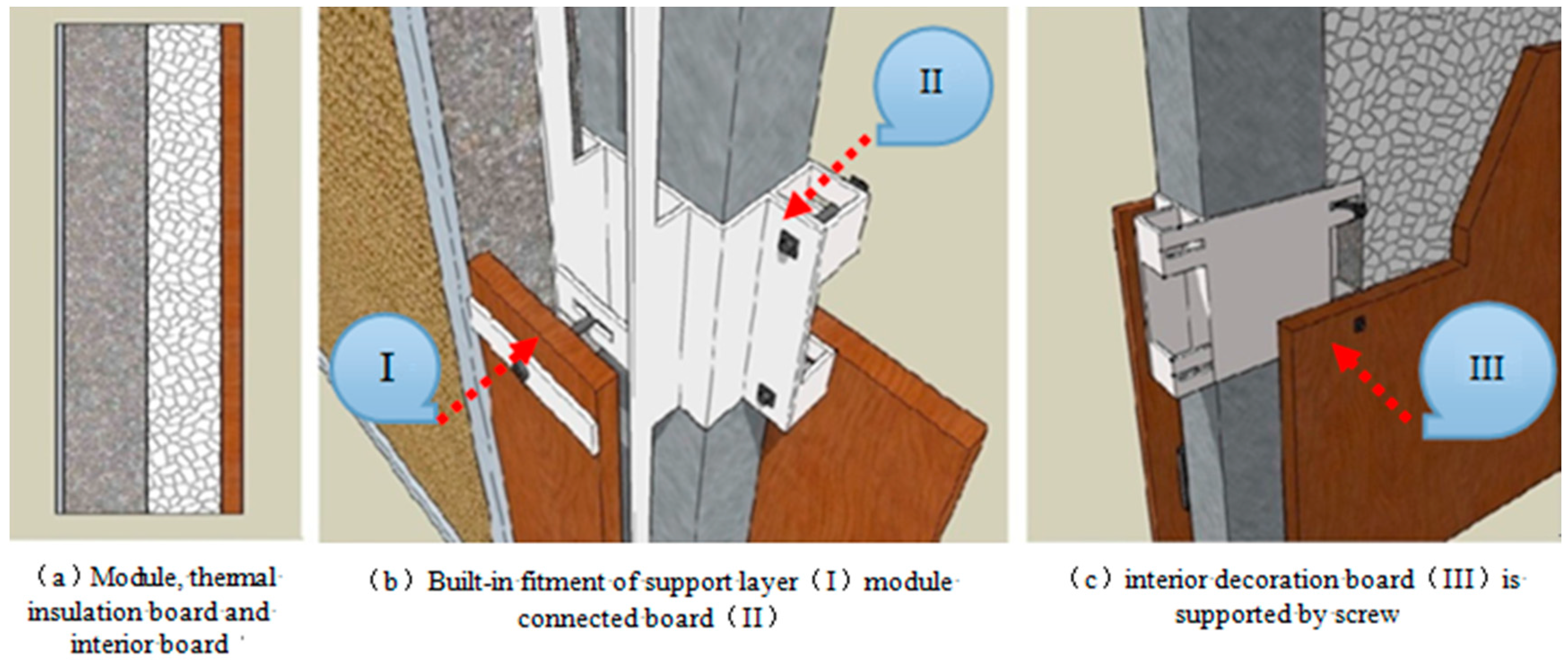
2.3. Module Installation

For any of the above modules, they need to be fixed onto the building frame column surface or roof in a firm, efficient, and safe way. To enable this, the supporting enclosure will be equipped with special hanging interfaces that are fixed to its side wall surfaces (see Figure 2a). During installation, the standard fixing supports will be bolted into the frame, before the enclosure (containing other elements—e.g., insulation, heat pipe panel, etc.) will be pressed into the slots fitted onto the supports via the interfaces, as shown schematically in Figure 2a–c. It should be noted that the dismantling of the module follows the opposite procedure as the assembly. This can be achieved by making detachable side edges (see Figure 2b) for the enclosure, thus allowing a single (or multiple) module(s) to be removed from the frame-fixing supports together with the slots bolted onto the supports. Compared with the traditional construction method, this proposed new prefabrication method has the advantages of safety, economy, high efficiency, and aesthetic appearance.
The building’s load-bearing frame uses a steel structure of light weight, good durability and high construction. The metal structure forms a frame which is mainly composed of a vertical frame and a horizontal frame as the main bearing, support, load transfer, and reinforcement structure. To prevent heat loss, the module and the interior decoration board is filled with 120 mm of thick rock wool board, as shown in Figure 3.
When the module is placed on the roof, the solar photovoltaic (or solar photovoltaic and solar thermal) components can be used. When the module is placed on the wall (or balcony), solar thermal components are more suitable with regards to efficiency and cost factors. However, if the roof area is not enough, solar photovoltaic (or solar photovoltaic and solar thermal) components are also applicable. Many modular insulation covers are connected together, forming the surface of decorations over the masonry or the roof, as shown in Figure 4a. Each module has the entrance pipe and the outlet pipe, while the lightweight flexible coupler is connected with a water pipe between modules. In this way, water can flow in any serial mode or parallel mode in circulation through the pressure chamber, forming a water circulation to achieve the required water amount and temperature, as shown in Figure 4b,c.
The new claddings could be made in standard modular sizes (such as the width of 0.5–2 m and the height of 0.5–2 m) by incorporating different elements. Numerous cladding modules can be connected together by adhesive, screws, or fasteners. These can form a wall/roof serving as the thermal insulation layer with (or without) the solar thermal/electrical generation function. In order to create a good aesthetic appearance, all the connecting parts, fixing parts, and sealing materials are hidden in the solar skin prefabricated module.

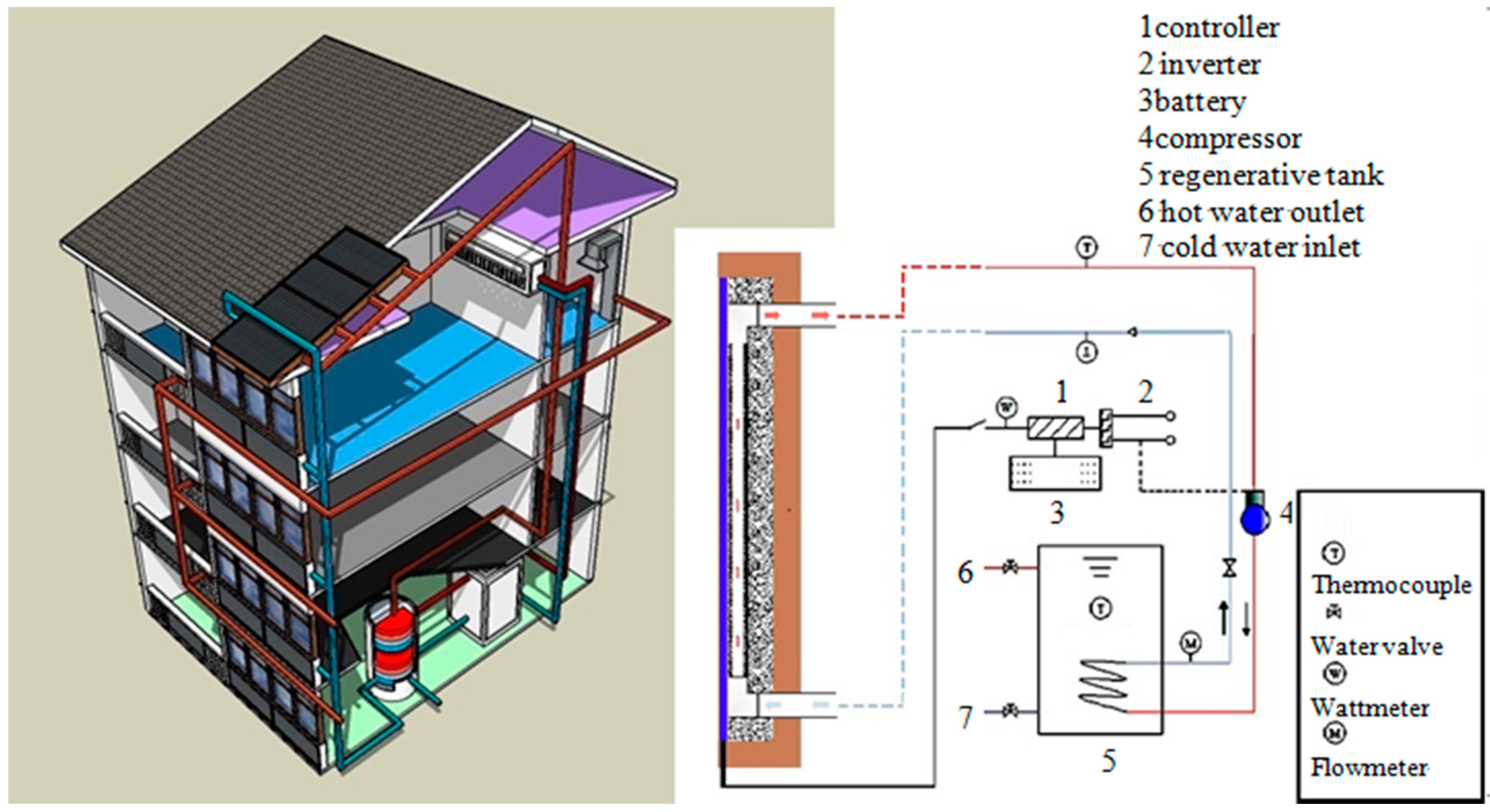
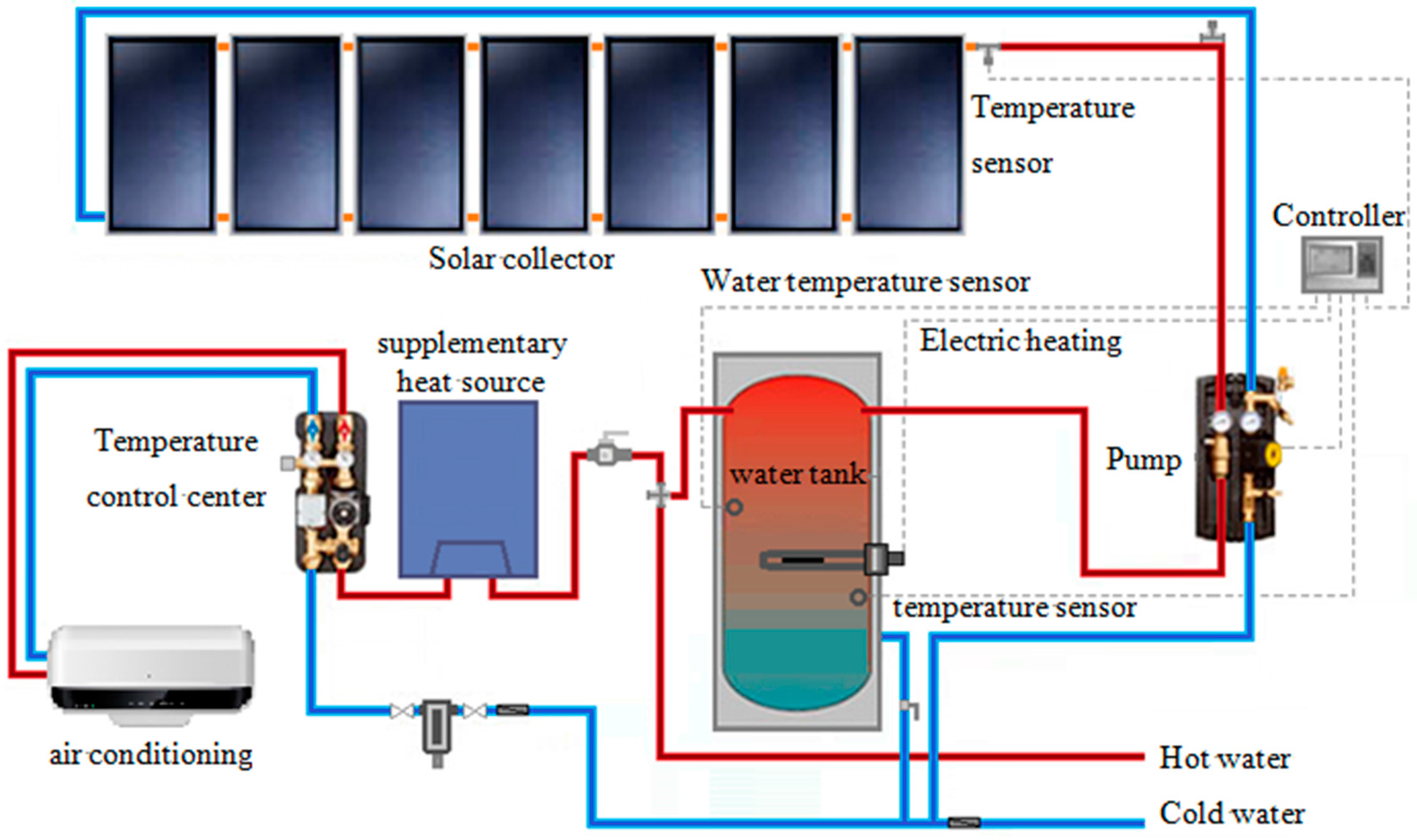
3. System Descriptions

The proposed system contains the outdoor and indoor parts that are linked together via the power and liquid transportation lines, as shown schematically in Figure 5. The outdoor part—structured as the modular solar building envelope (wall, roof, or balcony) incorporating the solar absorber and feeders (part of the inlet and outlet water pipes)—is designed to absorb solar energy in addition to acting as an alternative to the building insulation and decorative layer. The indoor part—comprised of the power control/storage unit, fluid transport routes, the hot water storage tank, and water piping—can convey the service power and water through this system.

3.1. Outdoor Part

The outdoor part is a multi-layer modular structure solar building envelope composed of the solar thermal systems, photovoltaic systems, or photovoltaic/thermal system through prefabrication based on the scale productivity technology. When the module is installed on the roof, the solar photovoltaic components (or solar photovoltaic and solar thermal components) are chosen. When the module is installed on the wall (or balcony), solar thermal components (or solar photovoltaic and solar thermal components) can be chosen, as shown in Figure 6.
As a part of the whole system, the module can expand or reduce its size according to the facade and roof size, which will decrease the interface of the original building structure and enhance aesthetic effects.

3.2. Indoor Part

The indoor part includes a hot water transfer line with excellent thermal insulation performance, a heat storage water tank, an auxiliary heat source, an absorption refrigeration air-conditioning, an electric/hot water storage/control unit, a circulating pump, and a cold-water return line, as shown in Figure 7. In the working condition, water pipelines will transfer hot water to the indoor hot water storage tank. The hot water is transported, respectively, to the bath and absorption refrigeration air-conditioning. The used cool water is transferred through the cold-water return pipeline back to the outdoor solar collector. Hot water in the heating circulating water pipes (about 70–80 °C in summer) can be used as the heat source of the absorption chiller, reducing the indoor air temperature while generating about 10 °C cooling water. If a modular solar building is equipped with a photovoltaic cell, the amount of electricity generated can drive the electric pump for heating/cooling, thereby possibly creating a near zero carbon heating/cooling system.
Due to weather and other reasons that may cause the mismatch of energy supply and demand, the power mismatch can be solved through the electric grid or battery. However, thermal mismatch is a complex problem which requires deep thought. For example, a short-term mismatch (daily/weekly) can be solved by thermal storage [22], while a long-term mismatch (seasonal mismatch, such as the summer heat surplus and winter heat shortage) is adjusted through boiler or suitable thermal storage system [23,24].

4. Data Analysis of Solar Envelope Structure Module

Yongxing Island is located in southern China, where the summer weather is hot and winter weather is warm. In order to study the efficiency of the modular system and its impact on the building energy consumption precisely, this research takes the local Yongxing Island soldiers’ dormitory (Figure 6) as a basic study object. The four-layer north–south-oriented dormitory has a height of 12 m and a length of 40 m. One of the key factors in maintaining a comfortable indoor living temperature is the thermal resistance of the building envelope against the outdoor thermal environment. The envelope specification of the selected target building is concluded in Table 3 through field investigation. The indoor temperature normally is kept as below 27 °C with the aid of mechanical air-conditoning system during between April and October annually. According to the design of the building envelope system module, the Energy-Plus energy consumption simulation software was used to analyze the basic energy consumption and efficiency.

4.1. Simulation Data of Module Energy Consumption

As the interface between building interiors and the outdoors, building envelopes play an important role in the energy efficiency of a building. In order to quantitatively analyze the building energy consumption, this paper makes a comparative analysis between a traditional building and a building equipped with the proposed solar module envelope by the simulation approach.

4.1.1. Establishment of Mathematics Model

The solar building envelope is a type of enclosure with a more complicated heat transformation process than an ordinary wall. The temperature field in the structure is a three-dimensional unsteady state, but the height and width are much larger than the thickness. The material of each layer is homogeneous, so the heat conduction in the module can be regarded as one-dimensional. The heat flow rate can be calculated through Fourier's Law as follows:
d Q = λ d t d n d A
where Q is the conductive heat flow rate, W; A is the heat conduction area, m2; λ is the thermal conductivity coefficient, W/m·K; and dt/dn is the temperature gradient, K/m.
As the module is composed of a multiple flat-wall structure, the heat conduction rate of each layer is equal in steady state. Applying Equation (1) to each layer:
Q 1 = λ 1 b 1 A ( t 1 t 2 ) = Δ t 1 R 1   That   is ,   Δ t 1 = Q 1 R 1
Q 2 = λ 2 b 2 A ( t 2 t 3 ) = Δ t 2 R 2   That   is ,   Δ t 2 = Q 2 R 2
Q n = λ n b n A ( t n t n + 1 ) = Δ t n R n   That   is ,   Δ t n = Q n R n
During the stable heat conduction process:
Q = Δ t 1 + Δ t 2 + + Δ t n R 1 + R 2 + R n = Δ t R = t 1 t n + 1 i = 1 n λ i A
where the inside surface temperature of b 1 , b 2 , b n and λ 1 , λ 2 , λ n is t 1 ,outside surface temperature is t n + 1 , temperature of the middle interface is t 2 , , t n .

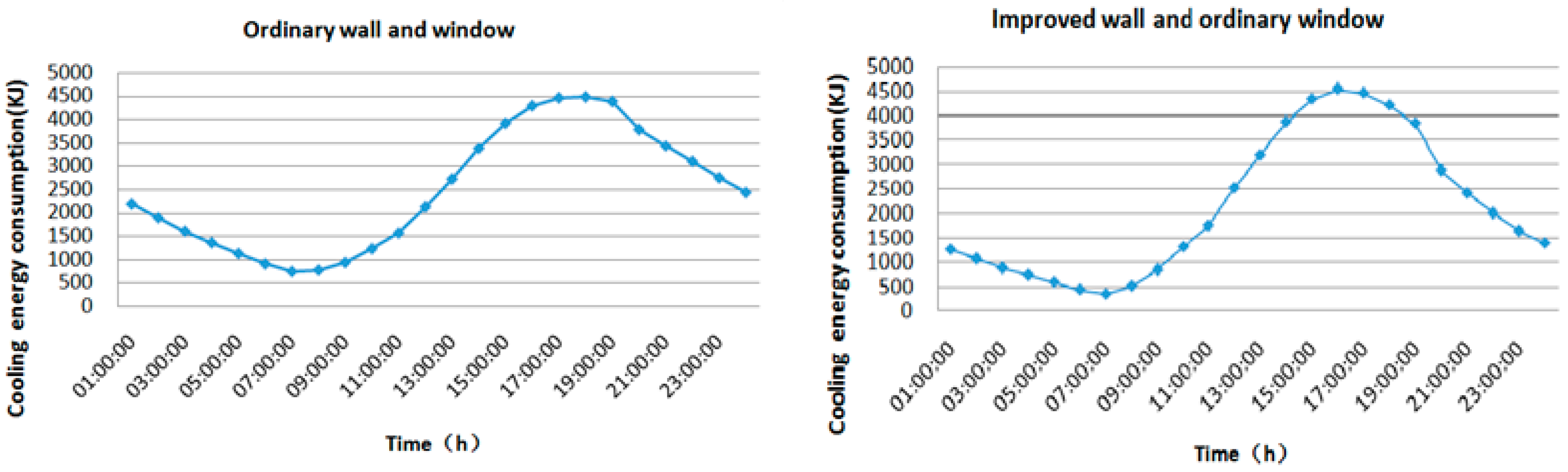
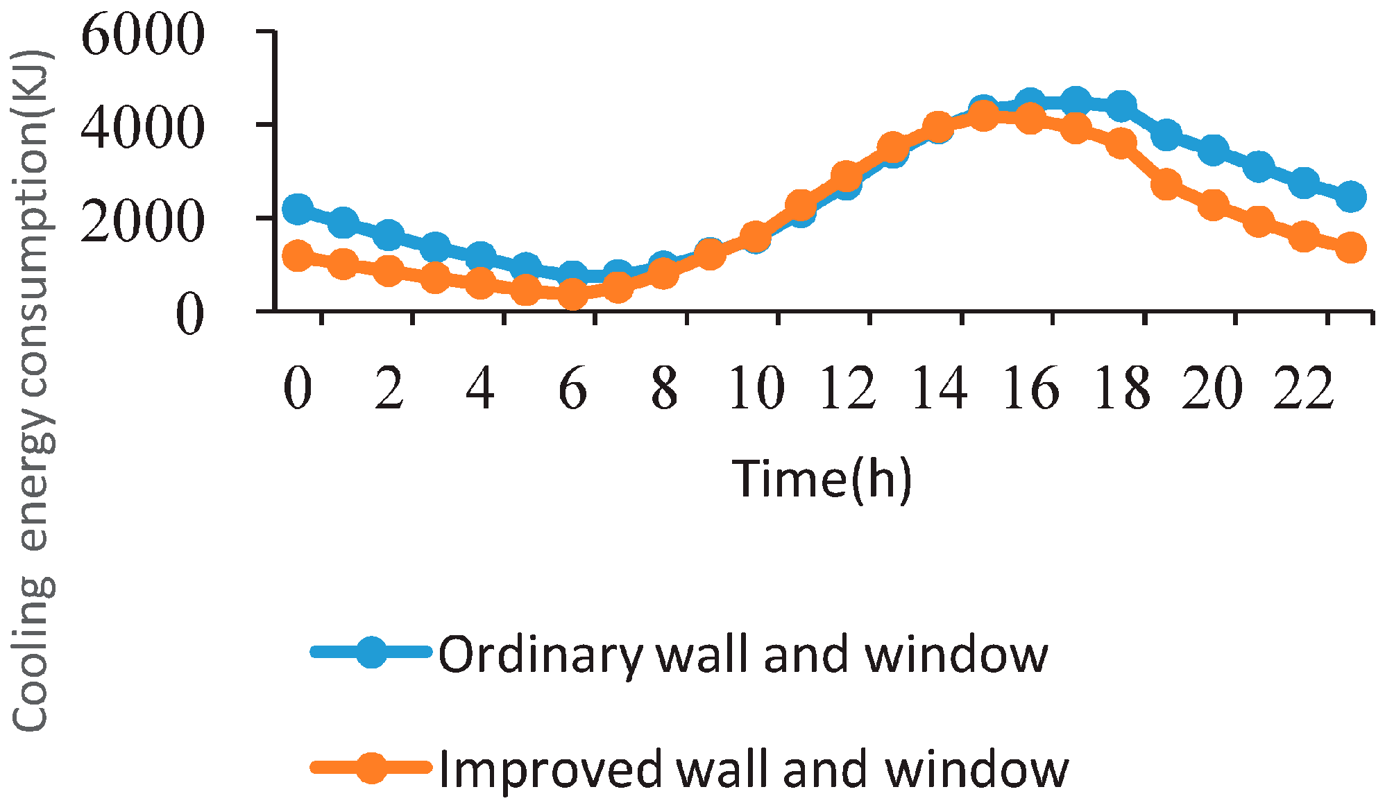
4.1.2. Simulation of Energy Consumption of Envelope Module Structure

In order to make a clear comparison of the energy consumption between the two different building envelopes, June 21st (the summer solstice) was selected as a typical summer day to carry out the simulation. Energy-Plus software was used to analyze the hourly cooling energy consumption of the soldiers’ dormitory building in a day. In the simulation, the following assumptions were made: heat transfer of convection and radiation was ignored; thermal conductivity, heat capacity, and other physical parameters of different materials were regarded as constants; and the joint between adjacent modules was considered seamless, neglecting the influence of gaps between different modules.
In the typical summer day, with the hourly data shown in Figure 8, the accumulated cooling energy consumption in a room with ordinary walls can be obtained as 59,783 kJ, while the energy consumption in a room with walls constructed by solar building envelope module is 50,940 kJ. This is 14.80% less than the former one.
A juxtaposition comparison is made to illustrate a more obvious difference in energy consumption in the two types of walls, as shown in Figure 9. The cooling energy consumption of optimized walls is lower than with ordinary walls from 12 a.m. to 10 a.m., but during 10 a.m. to 3 p.m., the energy consumption of the optimized walls becomes higher. After 4 p.m., the energy consumption of the optimized walls is once again lower than the ordinary walls.
The cooling energy consumption in the room with an optimized exterior-protected structure is always lower than the room with ordinary walls. The discrepancy between energy consumption in the two rooms reduces during 10 a.m. to 3 p.m., before obvious differences start to show again after 3 p.m.
Based on this analysis, compared with ordinary building envelopes, the solar module structure can effectively reduce the indoor cooling energy consumption.

4.2. Efficiency of the Modular System

The prototype of the solar building envelope system has five prefabricated solar epidermal modules. Each single module’s size is 2000 mm by 1000 mm by 200 mm, and has the expected output power/heat of 150/450 W. A single module is composed of a poly-silicon plate layer, micro-channel flat tube structure layer, phase change material, and heat insulation layer.
These layers are sealed in an insulating synthetic resin frame supporting structure. The structural parameters of the module are shown in Table 4.

4.2.1. Mathematical Model of Energy Transfer and Transformation Process

The energy transformation in the building envelope system has four parts. Firstly, photovoltaic panels absorb solar radiation energy, then the photovoltaic layer will convert part of the absorbed energy to electrical energy. The rest of the energy will be transferred to the micro-channel flat tube structure layer heating pipe fluid. Finally, the hot water outlet pipe allows for the hot water to flow to the water storage box for heat release. These processes are related to each other, and eventually become balanced to run smoothly. To simplify the simulation work, several hypotheses were put forward.
  • The system is in quasi-steady-state;
  • The surface area of all material layers has the same temperature;
  • The fluid in the pipe is in forced circulation;
  • The heat loss due to the superior thermal resistance of the insulation layer is ignored.
According to the area of solar panels and the surface area of the heat sink, the total efficiency of the PV/T system is ( E f ) [25]:
E f = η t + ε η e
where ηt is the heat efficiency of the PV/T system; ηe is the electronic efficiency of the PV/T system; and ε is the coverage rate of the photovoltaic battery.
The comprehensive photovoltaic heat and electronic efficiency of the PV/T system ( η ) is:
E f = η t + ε η e / η p o w e r
where ηpower is the power generation efficiency of a conventional heat power plant, which has a value of 0.38.
The daily average thermal efficiency of solar water heating systems η t is decided by the amount of solar radiation received on the collector surface during the test period H t ( M J / m 2 ) , initial temperature of the system T i (°C), and environmental temperature T a (°C). This is affected by other factors, such as water mass m (kg) and the inclination of the heat collector. The evaluation method for a natural circulation solar water heating system [26] is shown in Equation (8):
η t = q n e t H t = a 0 U s T i T a H t
where a 0 is the daily average heat efficiency when the system initial water temperature equals the daily environment temperature Ta; Us is the heat loss coefficient of system energy searching; Ti is the system initial water temperature in °C; and Ta is the environment temperature in °C.
Under the working conditions, the weather (solar radiation intensity, environmental temperature, etc.) and the initial water temperature of the system change. According to Equation (8), the typical thermal efficiency η t of the PV/T hot water system is used. η t is defined as the average thermal efficiency of the system when the initial water temperature and environment temperature is equal. It is also the index of PV/T system’s photo-thermal properties with different water amounts.
η t = η t U 1 T i T a H t
The efficiency of the PV/T photovoltaic system is mainly determined by the performance of the battery itself, which is affected by the operating temperature, dip angle, solar radiation intensity, and storage battery. The working temperature of the component is affected by the solar irradiance and the water temperature of the heat sink plate. Therefore, ignoring all other factors and referring to Equations (6) and (8), the typical photoelectric total efficiency of the PV/T hot water system η a is concluded. It is defined as the total photoelectric efficiency of the system when the initial water temperature is equal to the average ambient temperature.
η 0 = η 0 U 2 T i T a H t
According to Equation (6) and Equation (9), the typical comprehensive photovoltaic and thermal efficiency of the PV/T hot water system E f is concluded. It is defined as the comprehensive performance of the photovoltaic and thermal efficiency of the system when the initial water temperature is equal to the average daily temperature, as the measurement index of photovoltaic and thermal performance of different water amounts.
E f = E f U 3 T i T a H t
The typical thermal efficiency η t , typical photoelectric total efficiency η a , and typical comprehensive photovoltaic and thermal efficiency E f can evaluate the photo-thermal properties of the same PV/T system under different working conditions (mainly different water amounts).

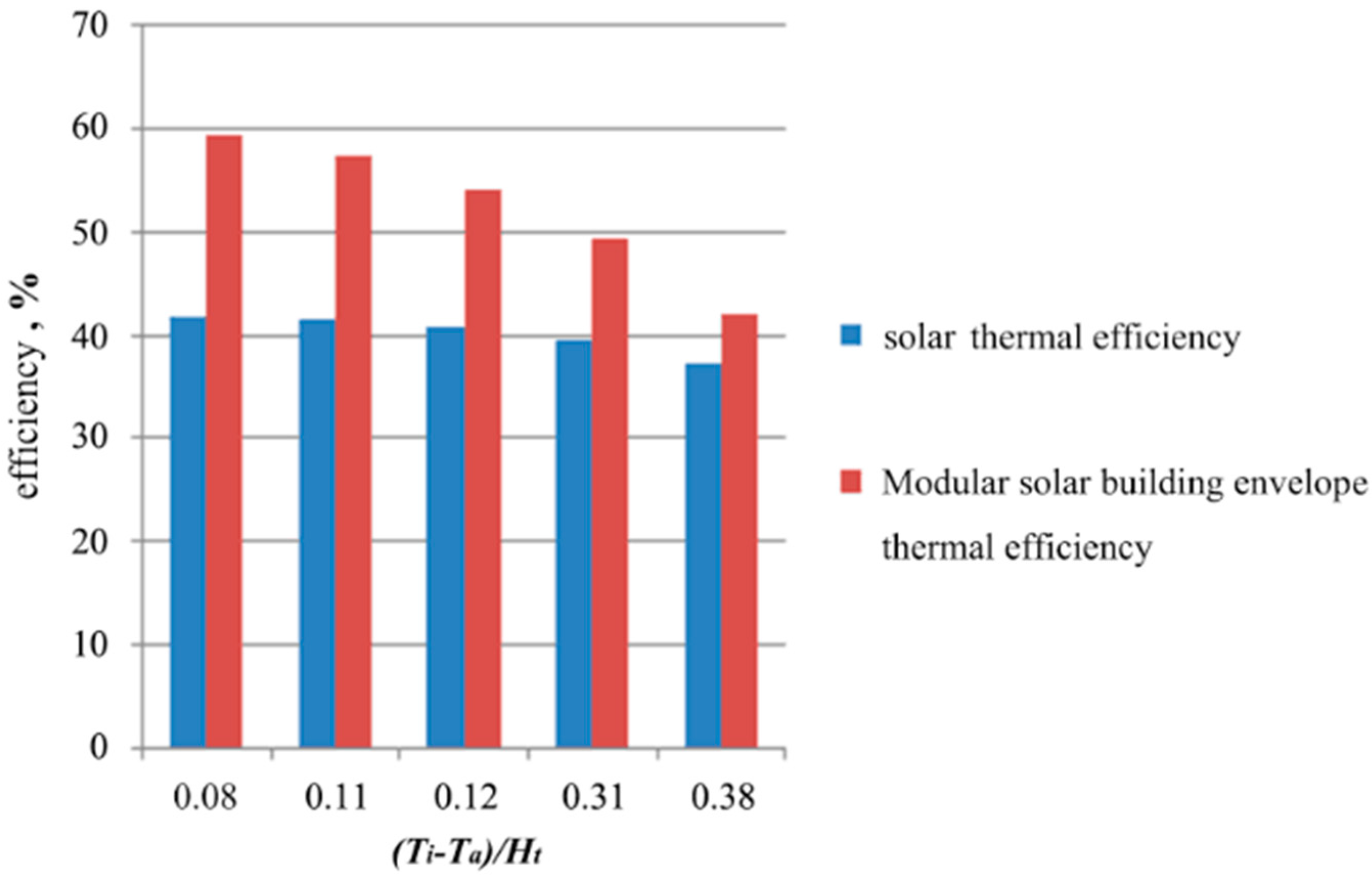
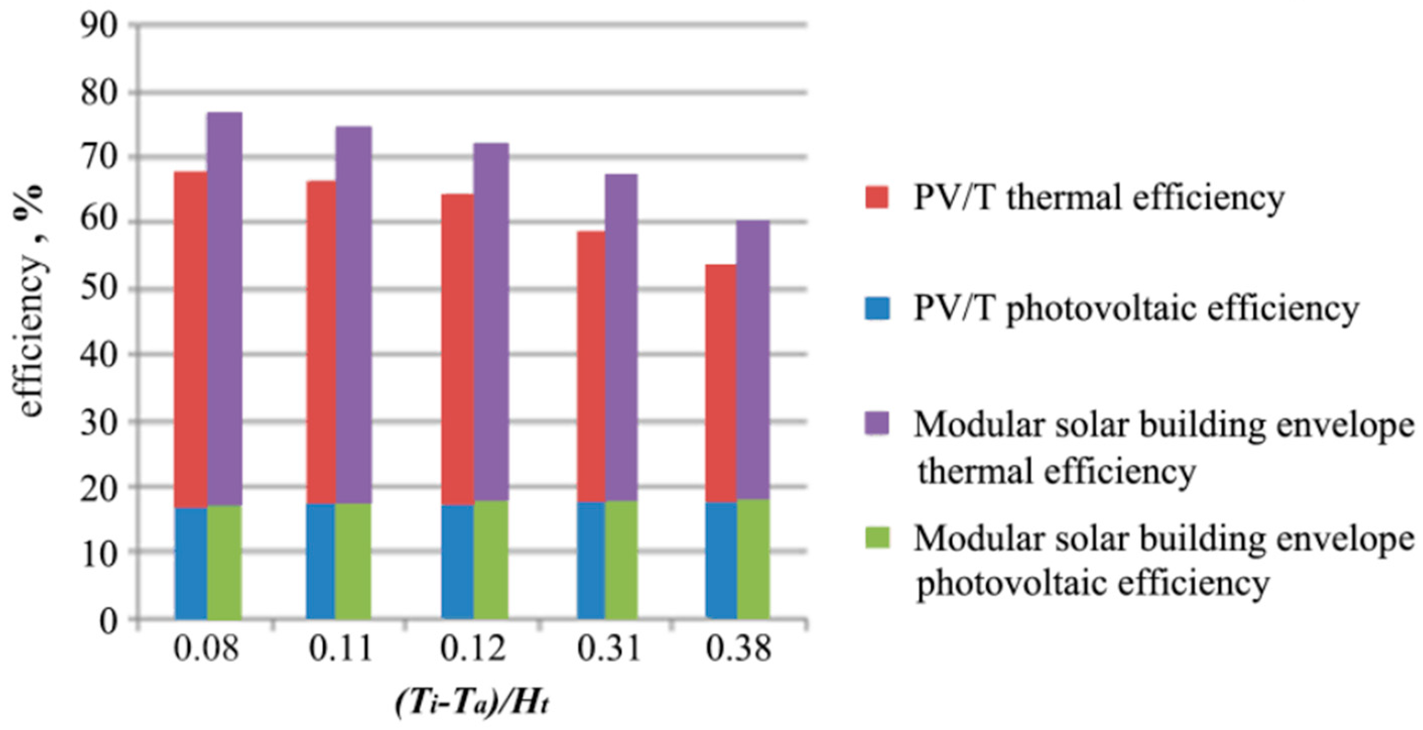
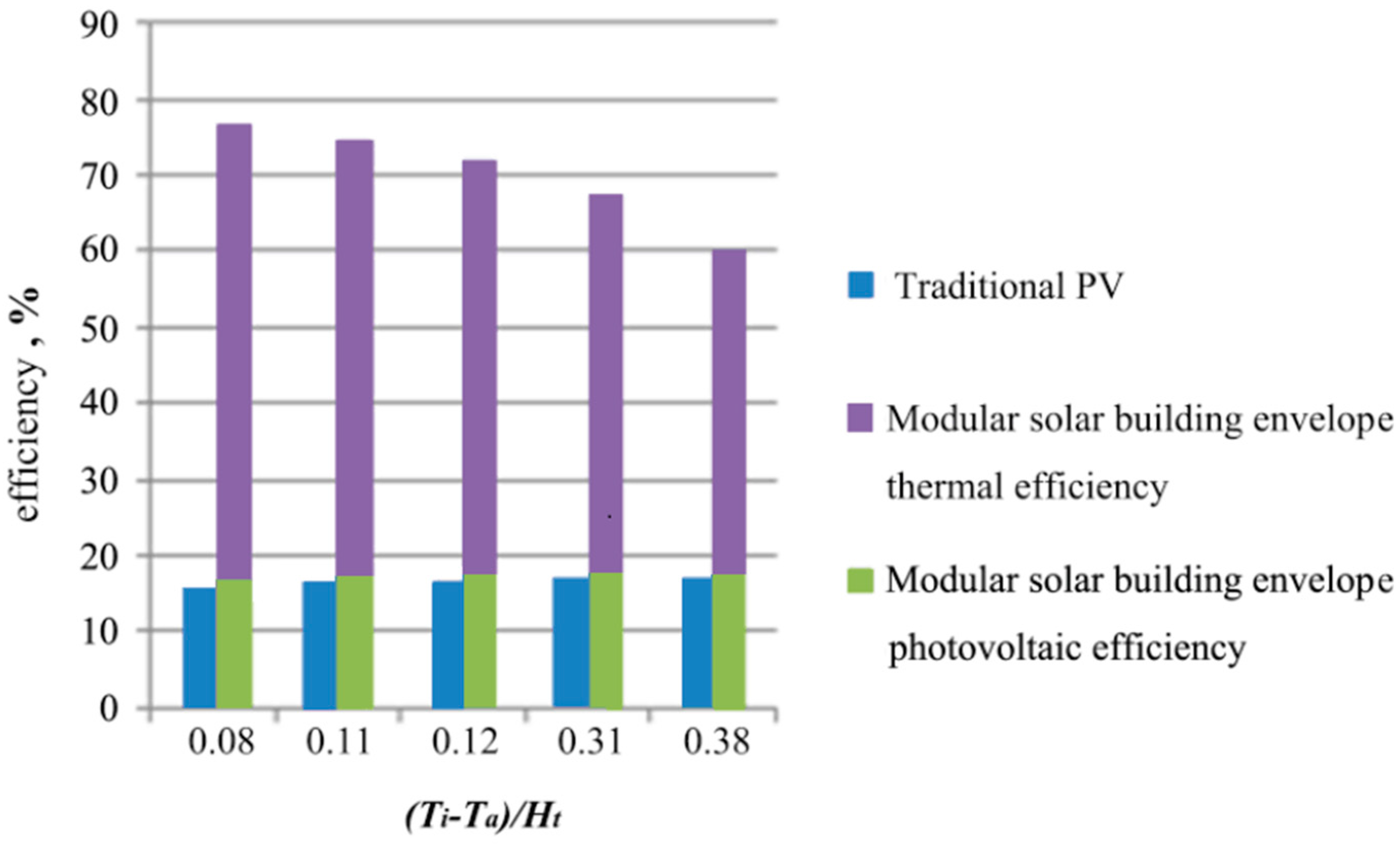
4.2.2. Efficiency Comparison of Solar Building Envelope Module, Conventional Solar Thermal System, PV, and PV/T

Compared with the conventional solar thermal system, PV and PV/T, the solar building envelope module can transfer more solar energy into usable energy, including heating and electrical power. The comparison results are as follows:
(1) Due to the increase in surface area of the micro-channel flat tube structure, the surface area that receives solar radiation increases accordingly. Therefore, more heating energy is generated, as shown in Figure 10. The heating efficiency is increased by 7.59% with the variation range of 41.97–59.47%.
(2) The solar building envelope module system can reduce the temperature of the solar battery panel effectively due to the cooling effect induced by the fluid underneath, so its electrical efficiency is higher than the solo PV system. On the contrary, the thermal efficiency is lowered, since the heat loss of the novel solar module is larger. The simulation result is shown in Figure 11. The electrical efficiency is increased by 3.51%, while the heating efficiency is in the range of 41.78–58.43%.
(3) Compared with the conventional PV/T system, the micro-channel flat tube structure of the solar building envelope module can effectively reduce the temperature of solar panels with better thermal energy collecting performance, so its heating and electrical efficiency is higher than the PV/T system. Under the same conditions, the solar building envelope structure module can increase the heating efficiency by 8.49% and the electrical efficiency by 0.31%, as shown in Figure 12.
(4) Based on the previous results, when the value of ( T i T a ) / H t increases, the module’s heating efficiency presents the trend of a linear declination with the range of 41.78% to 59.47%. The output efficiency of electrical power shows an inverse trend with the photovoltaic surface temperature, as a higher surface temperature results in a lower efficiency. The variation range is between 18.62% and 19.67%. In summary, the solar building envelope module has better performance advantages than the conventional solar thermal system, PV, and PV/T.

5. Conclusions

This study reviewed the solar building envelope module and practical applications of the recently emerging solar building envelope system. The results of this work help to understand the current status of the specific solar photovoltaic/thermal technology.
The solar building envelope module is a special type of facade combining the solar thermal collector into a building component. Unlike conventional solar thermal collectors, the solar building envelope module is an integrated device with solar-collecting, architectural, and structural functions. Compared to the simple physical combination between the facade and solar thermal collector, the simulated experimental results were recorded, analyzed, and compared under the equivalent operational conditions. Thus, this provided results and discussion of diagrams containing both experimental and simulation data, detailed as follows: (1) easy modular installation, 14.80% less than traditional building maintenance structure; (2) greater solar collecting capacity, the electrical efficiency is increased 3.51% compared to the traditional one, while the heating efficiency is in the range of 41.78–59.47%; (3) improved building thermal comfort and improved building thermal comfort and inhabitability; and (4) satisfactory aesthetic, technical, and safety performance.
One of the major difficulties in promoting the solar building envelope is to maintain both enhanced solar thermal efficiency and improved architectural integration. The current solar building envelope module has the problems of (1) complex structure; (2) low optical efficiencies; (3) easy over-heating; and (4) high capital cost. In terms of future development, five potential directions are suggested: (1) understand the mechanism of energy transfer and conversion occurring in the solar building envelope systems; (2) optimize their structural/geometrical configurations; (3) real-time measurement of the solar building envelope modular integrated buildings on a long-term scheme; (4) economic and environmental performance assessment and social acceptance analysis; as well as (5) dissemination, marketing, and exploitation strategies.

Author Contributions

Gang Ren and Xudong Zhao conceived the framework of this study; Gang Ren, Xudong Zhao and Hong Jin designed the Novel Modular Solar Building Envelope; Gang Ren, Hong Jin and Aishen Zhou conducted the simulation and analyzed the data; Gang Ren and Changhong Zhan wrote the paper.

Conflicts of Interest

The authors declare no conflict of interest.

References

  1. Roaf, S.; Brotas, L.; Nicol, F. Counting the costs of comfort. Build. Res. Inf. 2015, 43, 269–273. [Google Scholar] [CrossRef]
  2. Proposal for a Recast of the EPBD, Impact Assessment; European Communities: Brussels, Belgium, 2008.
  3. Peng, Y.; Wang, L.; Wang, W.; Cheng, L. Research progress of flat-plate solar collectors. Energy Energy Conserv. 2011, 8, 15–16. [Google Scholar]
  4. Zhu, D.; Yan, D. Calculation of solar radiation and generated energy on inclined plane and optimal inclined angle. Build. Sci. 2012, 28, 277–280. [Google Scholar]
  5. The Future of Heating: Meeting the Challenge. Available online: http://www.buildup.eu/en/practices/publications/future-heating-meeting-challenge-uk-heat-strategy (access on 19 June 2017).
  6. Shukla, R.; Sumathy, K.; Erickson, P.; Gong, J. Recent advances in the solar water heating systems: A review. Renew. Sustain. Energy Rev. 2013, 19, 173–190. [Google Scholar] [CrossRef]
  7. MacLeay, I.; Harris, K.; Annut, A. Digest of UK Energy Statistics 2012. Available online: https://www.gov.uk/government/statistics/digest-of-united-kingdom-energy-statistics-dukes-2012-printed-version-excluding-cover-pages (access on 19 June 2017).
  8. European Solar Thermal Technology Platform. Available online: http://www.solarthermalworld.org/keyword/european-solar-thermal-technology-platform (access on 19 June 2017).
  9. Zhang, X.; Shen, J.; Lu, Y.; He, W.; Xu, P.; Zhao, X.; Qiu, X.; Zhu, Z.; Zhou, J.; Dong, X. Active solar thermal facades (ASTFs): From concept, application to research questions. Renew. Sustain. Energy Rev. 2015, 50, 32–63. [Google Scholar] [CrossRef]
  10. Ibrahim, M.; Wurtz, E.; Anger, J.; Ibrahim, O. Experimental and numerical study on a novel low temperature facade solar thermal collector to decrease the heating demands: A south-north pipe-embedded closed-water-loop system. Solar Energy 2017, 147, 22–36. [Google Scholar] [CrossRef]
  11. Wolf, M. Performance analysis of combined heating and photovoltaic power systems for residences. Energy Convert. 1976, 16, 79–90. [Google Scholar] [CrossRef]
  12. Florschuetz, L.W. Extension of the Hottel-Whiller model to the analysis of combined photovoltaic/thermal flat plate collectors. Solar Energy 1979, 22, 361–366. [Google Scholar] [CrossRef]
  13. Clarke, J.A.; Hand, J.W.; Johnstone, C.M.; Kelly, N.; Strachan, P.A. Photovoltaic-integrated building facades. Renew. Energy 1996, 8, 475–479. [Google Scholar] [CrossRef]
  14. Fujisawa, T.; Tani, T. Annual exergy evaluation on photovoltaic-thermal hybrid collector. Solar Energy Mater. Solar Cells 1997, 47, 135–148. [Google Scholar] [CrossRef]
  15. Dupeyrat, P.; Menezo, C.; Fortuin, S. Study of the thermal and electrical performances of PVT solar hot water system. Energy Build. 2014, 68, 751–755. [Google Scholar] [CrossRef]
  16. Fraisse, G.; Menezo, C.; Johannes, K. Energy performance of water hybrid PV/T collectors applied to combisystems of direct solar floor type. Solar Energy 2007, 81, 1426–1438. [Google Scholar] [CrossRef]
  17. Kazanci, O.B.; Skrupskelis, M.; Sevela, P.; Pavlov, G.K.; Olesen, B.W. Sustainable heating, cooling and ventilation of a plus-energy house via photovoltaic/thermal panels. Energy Build. 2014, 83, 122–129. [Google Scholar] [CrossRef]
  18. Liao, W.; Ye, Y.; Shi, X.; Cui, H. Experimental study on influence of phase change material on the temperature of wall with photovoltaics. Build. Energy Effic. 2014, 8, 47–51. [Google Scholar]
  19. Li, J.; Wang, D.; Peterson, G.P. Experimental studies on a high performance compact loop heat pipe with a square flat evaporator. Appl. Therm. Eng. 2010, 30, 741–752. [Google Scholar] [CrossRef]
  20. Lu, X.; Hua, T.-C.; Liu, M.; Cheng, Y. Thermal analysis of loop heat pipe used for high-power LED. Thermochimica Acta 2009, 493, 25–29. [Google Scholar] [CrossRef]
  21. Yang, J.; Liu, Y.; Gu, M.; Peng, L.; Zhang, Y.; Gao, T. Research on cooling technology of solar photovoltaic cells. East China Electr. Power 2011, 39, 81–85. [Google Scholar]
  22. Rohsenow, W.; Hartnet, J.; Cho, Y. Handbook of Heat Transfer, 3rd ed.; McGraw-Hill: New York, NY, USA, 1998. [Google Scholar]
  23. Kumar, R. Estimation of solar collector area and thermal energy requirement in absorber heat recovery cycle. Heat Recovery Syst. CHP 1998, 8, 69–74. [Google Scholar] [CrossRef]
  24. Kalogirou, S. Economic analysis of solar energy systems using spread sheets. Renew. Energy 1996, 9, 1303–1307. [Google Scholar] [CrossRef]
  25. Luo, Q.; Tang, G.; Gong, G.; Tang, H. Analysis on energy saving approach for building hot water. Gas Heat 2004, 24, 3–5. [Google Scholar]
  26. Wu, R.; Yue, L.; Li, Q. Comparison of direct and indirect sewage source heat pump systems. HV AC 2011, 41, 111–114. [Google Scholar]
Figure 1. Schematic of a novel modular solar building envelope.
Energies 10 00880 g001
Figure 2. Installation process of modular solar building envelope.
Energies 10 00880 g002
Figure 3. Installation process of interior components.
Energies 10 00880 g003
Figure 4. Interior water supply network.
Energies 10 00880 g004
Figure 5. Principle of module-building integration system.
Energies 10 00880 g005
Figure 6. Outdoor appearance of the model building.
Energies 10 00880 g006
Figure 7. Schematic of the solar collector based hot water generation and refrigeration system.
Energies 10 00880 g007
Figure 8. Energy consumption of different building envelopes.
Energies 10 00880 g008
Figure 9. Energy consumption comparison of different walls.
Energies 10 00880 g009
Figure 10. Efficiency comparison of module system and conventional solar thermal system.
Energies 10 00880 g010
Figure 11. Efficiency comparison of module system and conventional PV system.
Energies 10 00880 g011
Figure 12. Efficiency comparison of module system and conventional PV/T system.
Energies 10 00880 g012
Table 1. Schematic diagram of solar thermal utilization module system and building.
Type/Structural DiagramsOperational Features
Energies 10 00880 i001
  • Converts both the direct and diffused solar irradiation into heat;
  • Works on the same principle as conventional unglazed solar thermal collectors;
  • Inside the facade, a double harp piping-system has several advantages, such as easy assembly, high compatibility of the various elements and longer contact time of the medium with the lamella (absorber) than in a simple harp-system
Active-unglazed solar façade
  • Hot water outlet;
  • Lamella (absorber);
  • Collecting pipe;
  • Insulating layer;
  • Masonry;
  • Air flow;
  • Cold water inlet
Table 2. Solar sandwich module and phase change core board structure.
Type/Structural DiagramsOperational Features
Energies 10 00880 i002
  • A glazing coverer (optional);
  • A plate with a selective treatment as solar absorber (optional);
  • A fluid-cooling circuit adhered to the absorber or glazing cover;
  • A back insulation layer;
  • The supporting enclosure;
The solar sandwich module can be either a glazed or an unglazed structure, and is usually opaque or transparent to buildings with the heat transfer media being air or hydraulic.
Englert Solar Sandwich
  • Thin film building integrated photovoltaics (BIPV);
  • Metal roof;
  • Fin sheet;
  • Thermal pipes;
  • Insulation;
Table 3. Parameters of building envelope.
Envelope ElementOriginal ParametersParameters of Module-Building Integration System
Exterior walls5 mm-thick thermal insulation coating
+20 mm thick cement mortar
+180 mm-thick aerated block
+20 mm-thick cement mortar
3 mm-thick fluorocarbon aluminum veneer decorative board
+70 mm-thick rock wool board
+25 mm-thick synthetic resin decorative board
+120 mm-thick polyurethane insulation board
+25 mm-thick synthetic resin decorative board
Floors100 mm-thick reinforced concrete floor100 mm-thick reinforced concrete floor
Roof100 mm-thick reinforced concrete floor
+10 mm-thick polystyrene thermal insulation
3 mm-thick fluorocarbon aluminum veneer decorative board
+70 mm-thick rock wool board
+25 mm-thick synthetic resin decorative board
+120 mm-thick polyurethane insulation board
+25 mm-thick synthetic resin decorative board
WindowWindow/wall ratio: 55% south, north 55%Window/wall ratio: 55% south, north 55%
Table 4. Structural parameters of the solar building envelope.
StructureParameterNumerical Value
PV cellBattery efficiency under standard operating conditions15
PV cell temperature coefficient/K−10.0040
Thickness/m0.0003
CollectorEmissivity %84
Absorptivity %90
Equivalent thermal conductivity (W·m−1·K−1)198
Equivalent thickness/m0.001
Flat tubeFlat tube thickness/m0.01
Flat tube length/m0.02
Junction thermal resistance/(m2·K·W−1)0
Heat transfer coefficients inside a tube/(W·m−2·K−1)300
Fluid heat capacity inside a tube/(kJ·kg−1·K−1)4.2
Heat insulation layerThermal conductivity (W·m−1·K−1)0.045
Bottom insulation thickness/m0.030
Edge insulation thickness/m0.025
External fixing frameThermal conductivity (W·m−1·K−1)0.04
Bottom frame thickness/m0.025
Edge frame thickness/m0.025

