
Economic Power Schedule and Transactive Energy through an Intelligent Centralized Energy Management System for a DC Residential Distribution System


Abstract
:1. Introduction
2. Structures of the DC Residential Distributed System (RDS)
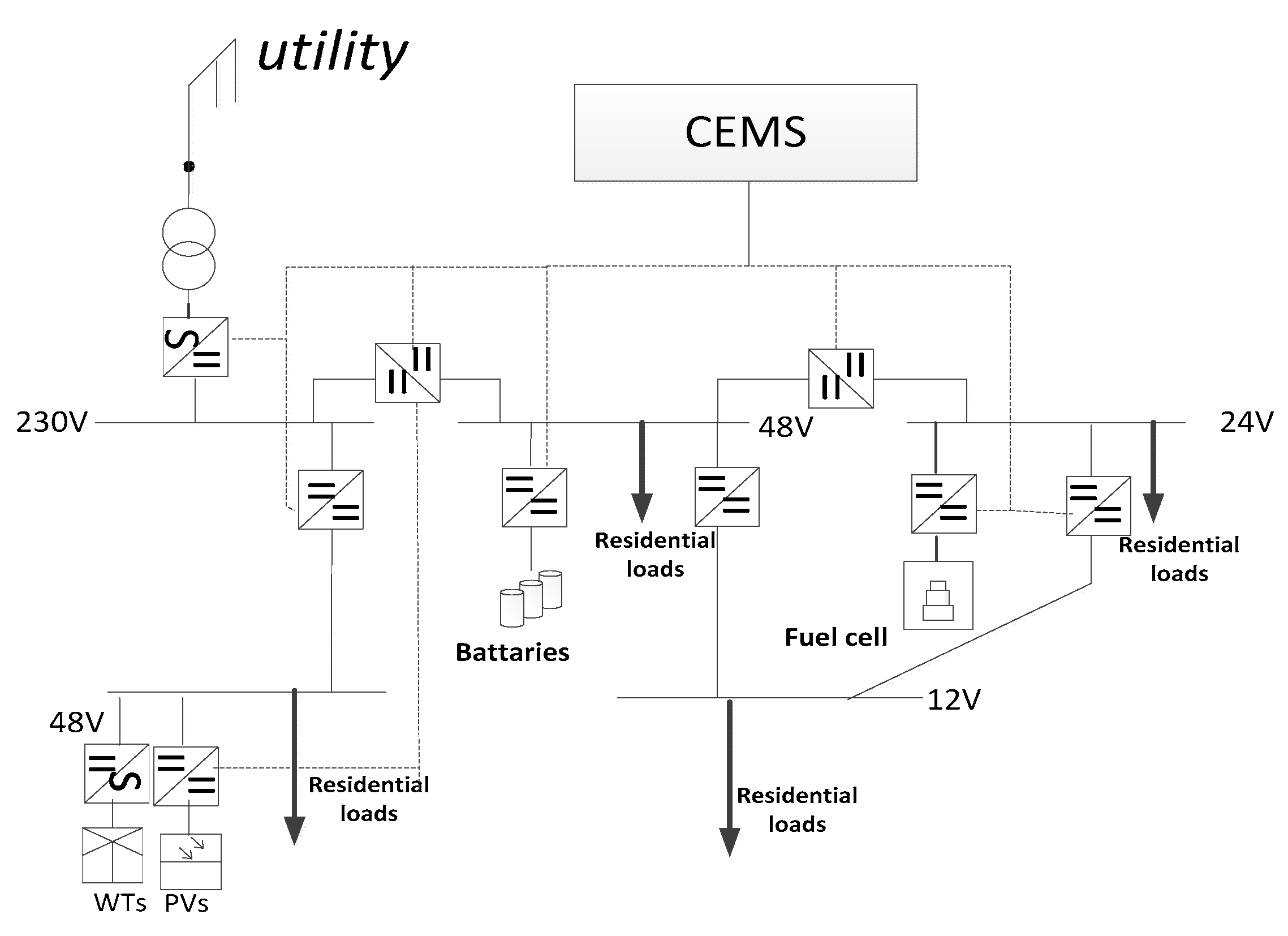
2.1. Power Architecture of the DC RDS
- (1)
- Distributed generators: composed of PV panels and wind turbines in series or in parallel. The maximum peak power tracking (MPPT) technology is implemented to emphasize high efficiency in the DC RDS.
- (2)
- Converters: these are responsible for the charge and discharge of buses with loads and generations. A unidirectional DC–DC converter is used for connecting PV and DC load with DC buses with different voltage levels; a bi-directional DC–DC converter is used for connecting batteries energy storage system (BESS) with 48 V DC bus. An AC–DC converter is used for AC distributed power with DC bus. The DC residential area is connected to the utility grid through a centralized bi-direction converter.
- (3)
- Buses: all system components including DGs, loads, ESS, etc., are connected to multi-voltage lever buses by converters. DC Buses with 230 V, 48 V, 24 V and 12 V are deployed in this DC RDS [25].
- (4)
- Energy storage system (ESS): composed of advances in the Li-ion battery technology in parallel or in a series, which can not only be utilized to absorb excessive power and to carry out charging and discharging as the signal from the EMS, but also has a fast response time following the cooperation control [26,27].
- (5)
- Information system (IS): this, with aid of wireless communication and the smart meter, is imperative for achieving TE. The DC living home lab in Aalborg is equipped with a Zigbee smart device that is flexible and comfortable for user experience [28].
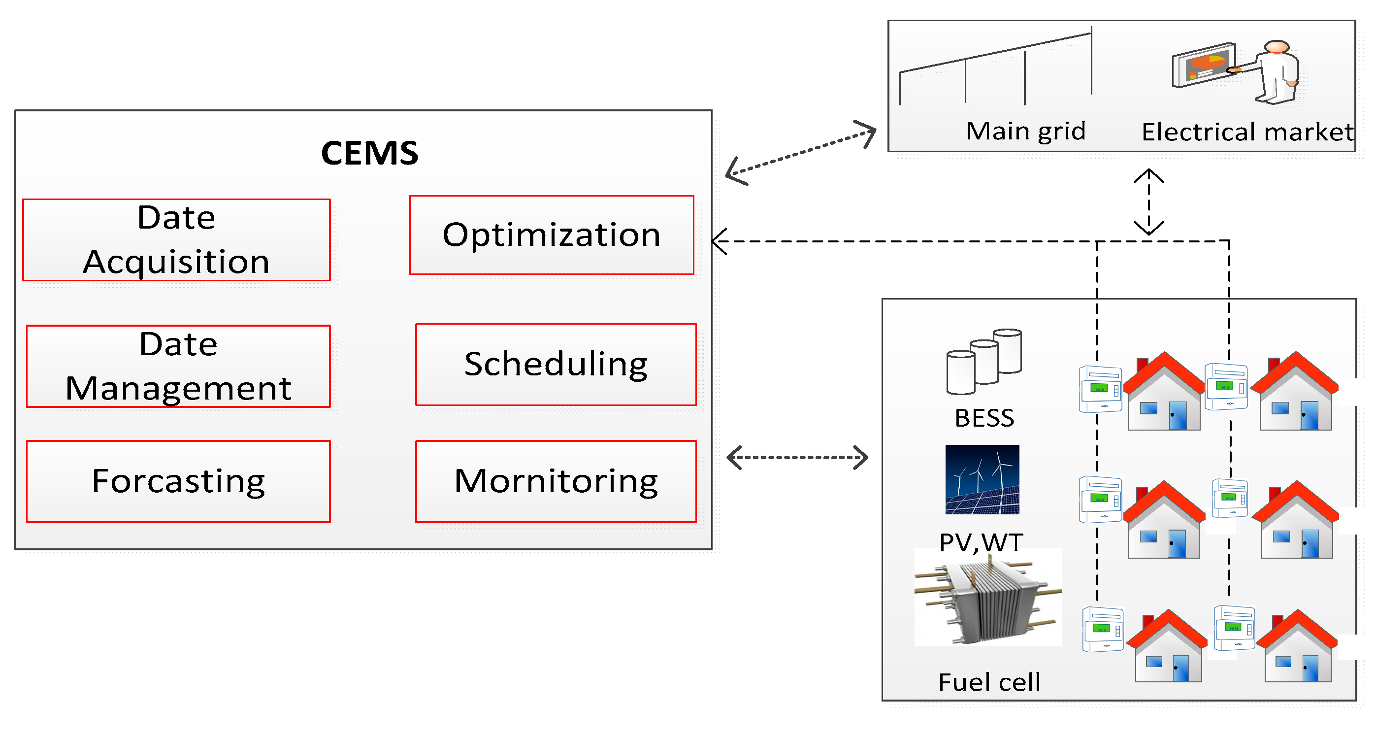
2.2. Centralized Energy Management System
- Collecting and managing local information, e.g., load date, generation power, smart meter dates.
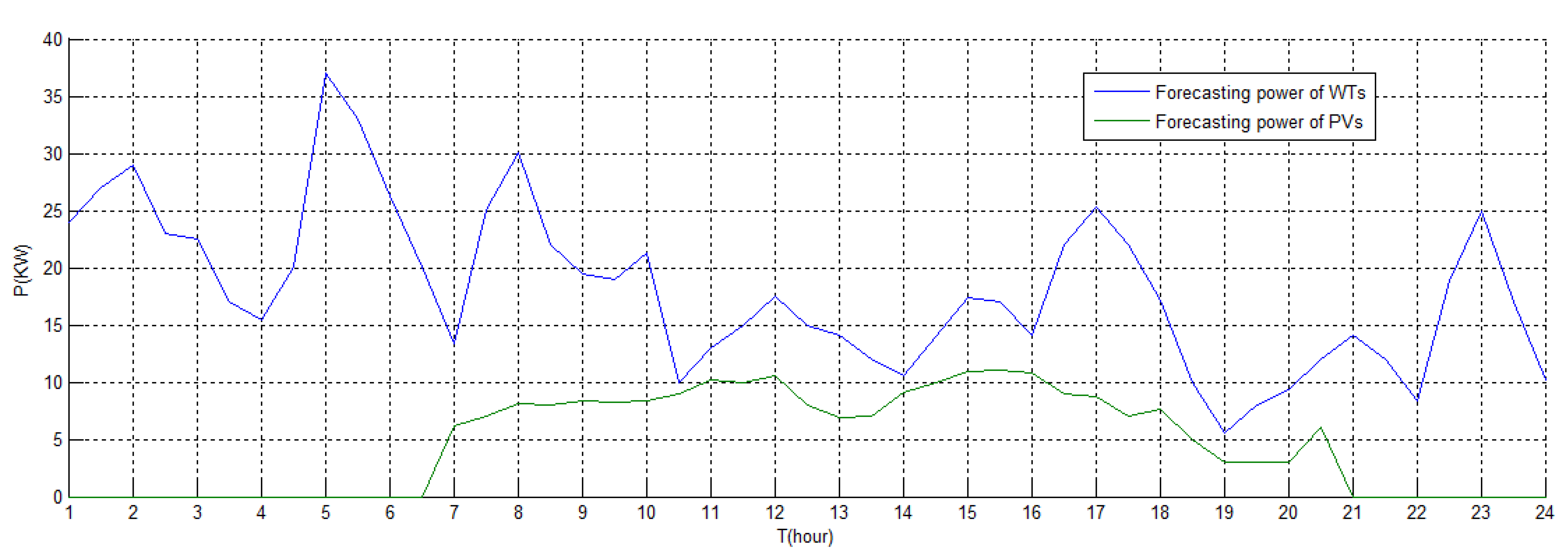
- Forecasting DER information, e.g., load, the power of WTs, PVs.
- Main grid information, e.g., real-time electrical price, demand response information.
- Monitoring the whole system, e.g., state of charge of the ESS, security and reliability constraints of the DC residential system.
- The expert system, e.g., optimization algorithms for various objectives, constraints and operational limits of units.
- The output variables of the EMS are the reference values for the control system (e.g., output power and/or terminal voltage) for each dispatchable DER.
3. The Control and Implementing System in the DC System
3.1. Adaptive Droop Control in the DC Distributed Power System (Network)
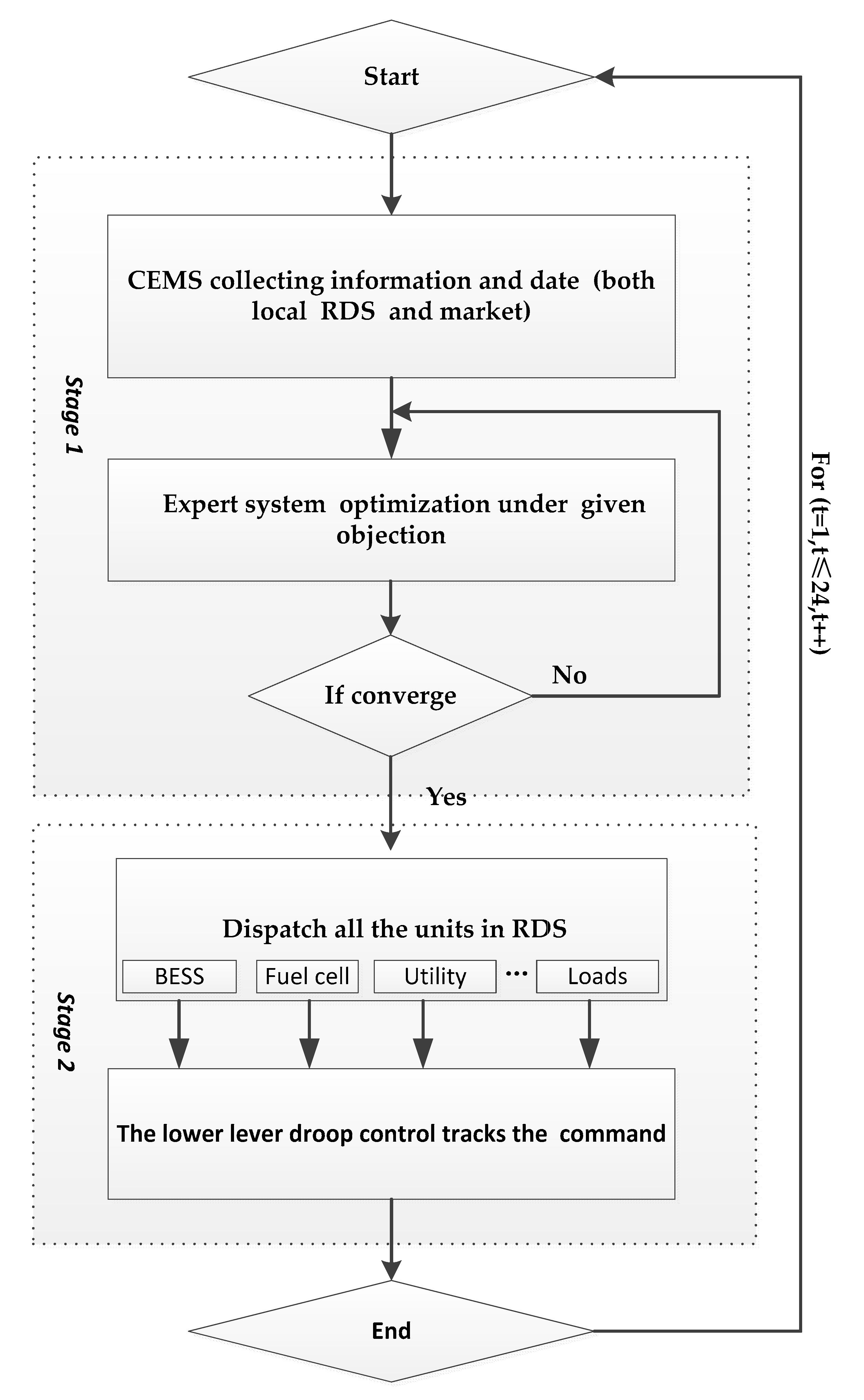
3.2. Flow Chart of Schedule and TE
4. Optimization for Economic Operation in the DC Residential System
4.1. Cost Composition in the DC System
4.2. Objective Function
4.3. Constraints
5. Case Study
6. Conclusions and Future Work
Acknowledgments
Author Contributions
Conflicts of Interest
Appendix A

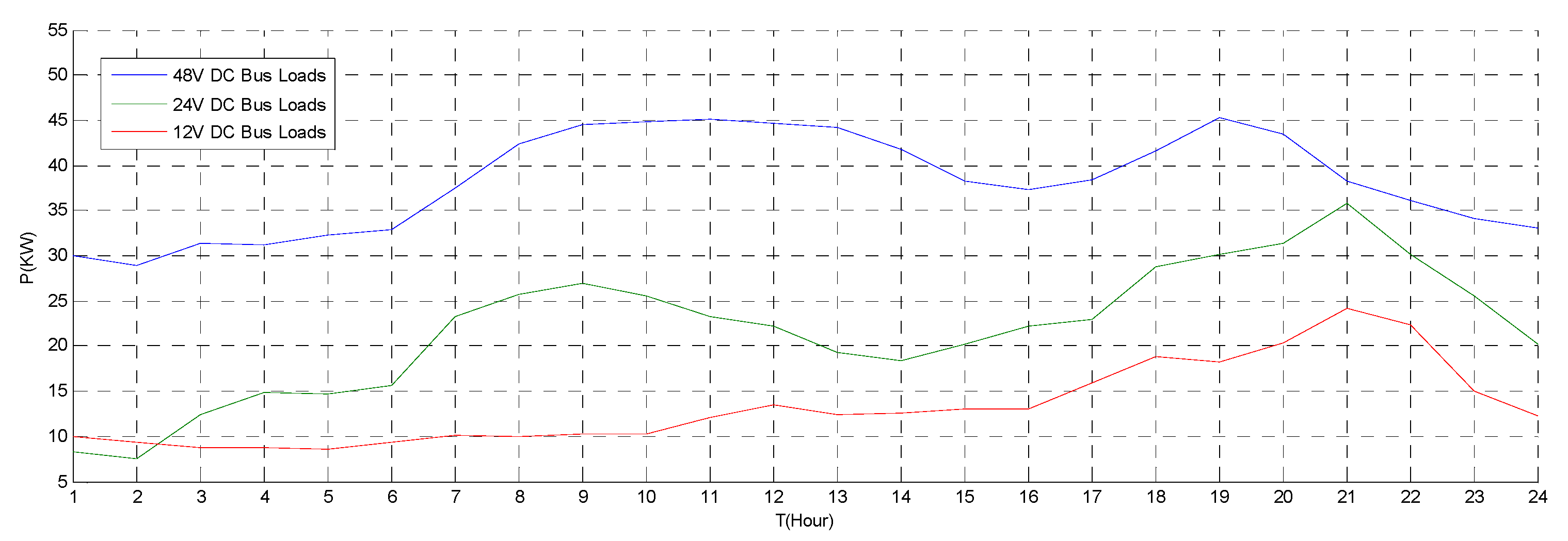
| Time | Load (48 V) | Load (24 V) | Load (12 V) | WT | PV |
|---|---|---|---|---|---|
| 00–01 | 30.1 | 8.3 | 10 | 24 | 0 |
| 01–02 | 28.5 | 7.4 | 9.4 | 29 | 0 |
| 02–03 | 31.9 | 12.6 | 8.7 | 22.55 | 0 |
| 03–04 | 32.2 | 31.7 | 8.6 | 15.43 | 0 |
| 04–05 | 33.4 | 14.9 | 8.3 | 37.05 | 0 |
| 05–06 | 33.9 | 15.5 | 9.2 | 26.22 | 0 |
| 06–07 | 37.2 | 24.3 | 10.1 | 13.34 | 6.12 |
| 07–08 | 42.2 | 25.8 | 10.1 | 30.06 | 8.09 |
| 08–09 | 44.8 | 27.1 | 10.5 | 19.4 | 8.33 |
| 09–10 | 45 | 26 | 10.8 | 21.32 | 8.4 |
| 10–11 | 45.2 | 23.7 | 13.8 | 0.33 | 10.23 |
| 11–12 | 44.6 | 24 | 14.2 | 17.56 | 10.57 |
| 12–13 | 43.9 | 19.6 | 13.8 | 14.03 | 6.88 |
| 13–14 | 42 | 18 | 14.1 | 10.53 | 9.06 |
| 14–15 | 38 | 20 | 14.4 | 17.32 | 10.89 |
| 15–16 | 37.3 | 23.3 | 14.8 | 14.06 | 10.75 |
| 16–17 | 38.2 | 24 | 15.4 | 25.3 | 8.77 |
| 17–18 | 42.8 | 28.7 | 19.3 | 17.15 | 7.65 |
| 18–19 | 45 | 30.3 | 18.8 | 5.5 | 3.03 |
| 19–20 | 43.9 | 32.4 | 20.2 | 9.35 | 2.98 |
| 20–21 | 38.8 | 35.2 | 28.6 | 14.09 | 0 |
| 21–22 | 36.6 | 30.1 | 23.4 | 8.33 | 0 |
| 22–23 | 34.7 | 25.1 | 15 | 24.9 | 0 |
| 23–24 | 33.3 | 20.3 | 13 | 10.23 | 0 |
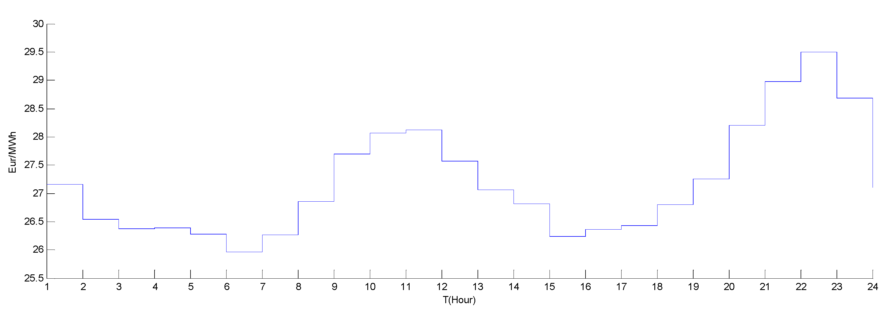
| Time | 00–01 | 01–02 | 02–03 | 03–04 | 04–05 | 05–06 | 06–07 | 07–08 | 08–09 | 09–10 | 10–11 | 11–12 |
|---|---|---|---|---|---|---|---|---|---|---|---|---|
| Price | 27.16 | 26.54 | 26.37 | 26.39 | 26.28 | 25.96 | 26.27 | 26.85 | 27.69 | 28.06 | 28.12 | 27.57 |
| Time | 12–13 | 13–14 | 14–15 | 15–16 | 16–17 | 17–18 | 18–19 | 19–20 | 20–21 | 21–22 | 22–23 | 23–24 |
| price | 27.06 | 26.81 | 26.23 | 26.36 | 26.43 | 26.8 | 27.26 | 28.2 | 28.97 | 29.5 | 28.68 | 27.1 |
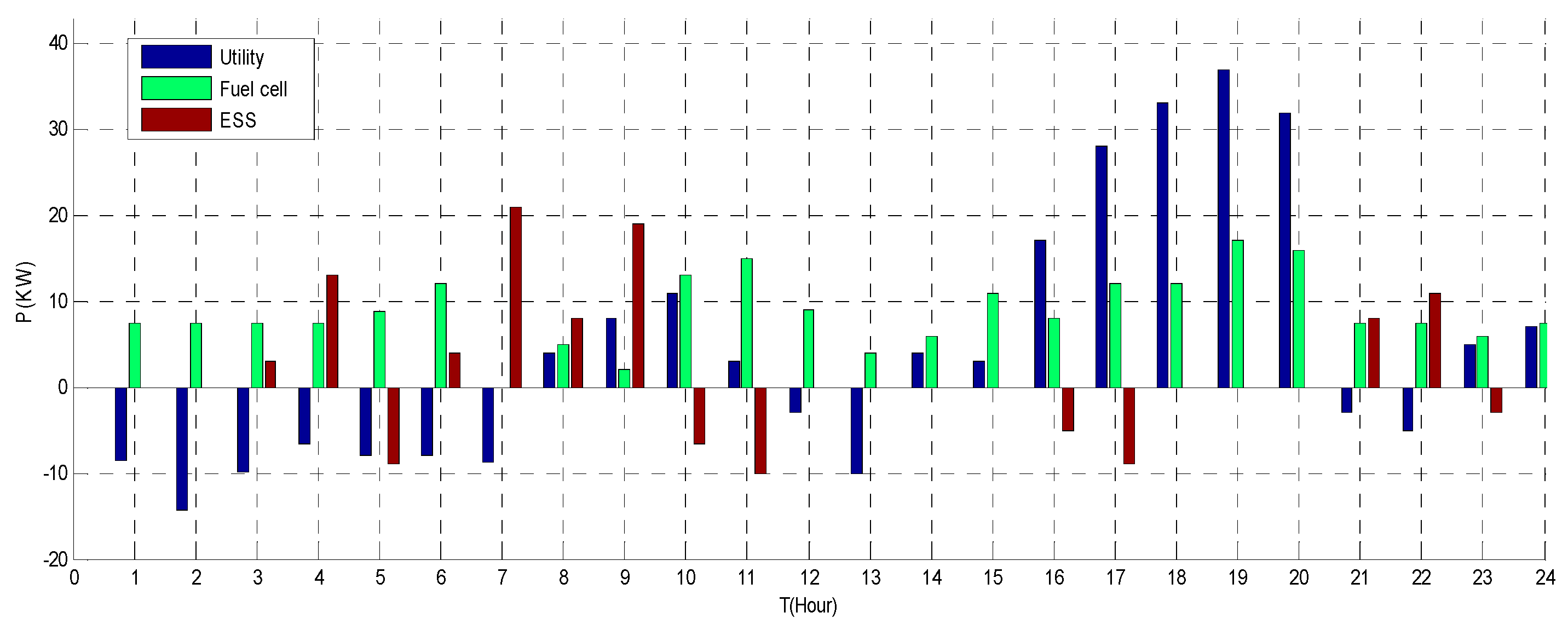
| Controlled Units | Constraint |
|---|---|
| Utility | (−50, 50) |
| ESS | (−40, 40) |
| Fuel cell | (0, 50) |
References
- Aryani, D.R.; Song, H. Coordination Control Strategy for AC/DC Hybrid Microgrids in Stand-Alone Mode. Energies 2016, 36, 1–20. [Google Scholar] [CrossRef]
- Li, C.; de Bosio, F.; Chaudhary, S.K.; Graells, M.; Vasquez, J.C.; Guerrero, J.M. Operation cost minimization the droop-controlled DC microgrids based on real-time pricing and optimal power flow. In Proceedings of the IECON 2015—41st Annual Conference of the IEEE Industrial Electronics Society, Yokohama, Japan, 9–12 November 2015; pp. 3905–3909. [Google Scholar]
- Guerrero, J.M.; Vasquez, J.C.; Matas, J.; de Vicuña, L.G.; Castilla, M. Hierarchical control of droop-controlled AC and DC microgrids—A general approach toward standardization. IEEE Trans. Ind. Electron. 2011, 58, 158–172. [Google Scholar] [CrossRef]
- Lu, X.; Wan, J. Modeling and control of the distributed power converters in a standalone DC microgrid. Energies 2016, 9, 217. [Google Scholar] [CrossRef]
- Riccobono, A.; Ferdowsi, M.; Hu, J.; Wolisz, H.; Jahangiri, P.; Müller, D.; De Doncker, R.W.; Monti, A. Next generation automation architecture for DC smart homes. In Proceedings of the 2016 IEEE International Energy Conference (ENERGYCON), Leuven, Belgium, 4–8 April 2016. [Google Scholar]
- Li, C.; Chaudhary, S.K.; Dragicevic, T.; Vasquez, J.C.; Guerrero, J.M. Power flow analysis for DC voltage droop controlled DC microgrids. In Proceedings of the 2014 11th International Multi-Conference on Systems, Signals & Devices (SSD), Barcelona, Spain, 11–14 February 2014. [Google Scholar]
- Email, D. Intelligent DC Microgrid Living Laboratories—A Chinese-Danish Cooperation Project. In Proceedings of the 2015 IEEE First International Conference on DC Microgrids (ICDCM), Atlanta, GA, USA, 7–10 June 2015; pp. 365–370. [Google Scholar]
- Rahimi, B.F.; Ipakchi, A. Using a Transactive Energy Framework: Providing Grid Services from Smart Buildings. IEEE Electr. Mag. 2016, 4, 23–29. [Google Scholar] [CrossRef]
- Pratt, B.A.; Krishnamurthy, D.; Ruth, M. Transactive Home Energy Management Systems. IEEE Electr. Mag. 2016, 4, 8–14. [Google Scholar] [CrossRef]
- Akter, M.N.; Mahmud, M.A.; Oo, A.M.T. A hierarchical transactive energy management system for microgrids. In Proceedings of the 2016 IEEE Power and Energy Society General Meeting, Boston, MA, USA, 17–21 July 2016; pp. 1–5. [Google Scholar]
- Amin, U.; Ieee, S.M.; Hossain, M.J.; Ieee, S.M.; Lu, J.; Ieee, S.M. Cost-Benefit Analysis for Proactive Consumers in a Microgrid for Transactive Energy Management Systems. In Proceedings of the 2016 Australasian Universities Power Engineering Conference (AUPEC), Brisbane, Australia, 25–28 Septemper 2016; pp. 25–28. [Google Scholar]
- World’s First Blockchain-Managed Energy Transaction. Available online: http://www.theepochtimes.com/n3/2027695-worlds-first-peer-to-peerenergy-transaction-on-the-blockchain-has-arrived/ (accessed on 6 July 2016).
- Akter, M.N.; Mahmud, M.A.; Oo, A.M.T. Comprehensive economic evaluations of a residential building with solar photovoltaic and battery energy storage systems: An Australian case study. Energy Build. 2017, 138, 332–346. [Google Scholar] [CrossRef]
- Han, Y.; Chen, W.; Li, Q. Energy Management Strategy Based on Multiple Operating States for a Photovoltaic/Fuel Cell/Energy Storage DC Microgrid. Energies 2017, 10, 136. [Google Scholar] [CrossRef]
- Meng, L.; Sanseverino, E.R.; Luna, A.; Dragicevic, T.; Vasquez, J.C.; Guerrero, J.M. Microgrid supervisory controllers and energy management systems: A literature review. Renew. Sustain. Energy Rev. 2016, 60, 1263–1273. [Google Scholar] [CrossRef]
- Khodayar, M.E.; Manshadi, S.D.; Vafamehr, A. The short-term operation of microgrids in a transactive energy architecture. Electr. J. 2016, 10, 41–48. [Google Scholar] [CrossRef]
- Nunna, H.S.V.S.K.; Doolla, S. Energy Management in Microgrids Using Demand Response and Distributed Storage—A Multiagent Approach. IEEE Trans. Power Deliv. 2013, 28, 939–947. [Google Scholar] [CrossRef]
- Kim, T.; Yun, J.; Qiao, W. A multiagent system for residential DC microgrids. In Proceedings of the 2015 IEEE Power & Energy Society General Meeting, Denver, CO, USA, 26–30 July 2015. [Google Scholar]
- Dou, C.; Yue, D.; Han, Q.; Guerrero, J.A. Multi-Agent System Based Event-Triggered Hybrid Control Scheme for Energy Internet. IEEE Access 2017, 3536, 3263–3272. [Google Scholar] [CrossRef]
- Sakib, N.; Hossain, J.; Ibrahim Bulbul, H.; Hossain, E.; Bayindir, R. Implementation of Unit Commitment Algorithm: A Comprehensive Droop Control Technique to Retain Microgrid Stability. In Proceedings of the 2016 IEEE International Conference on Birmingham Renewable Energy Research and Applications (ICRERA), Birmingham, UK, 20–23 November 2016. [Google Scholar]
- Vasquez, J.C.; Guerrero, J.M.; Luna, A.; Rodriguez, P.; Teodorescu, R. Adaptive Droop Control Applied to Voltage-Source Inverters Operating in Grid-Connected and Islanded Modes. IEEE Trans. Ind. Electron. 2009, 56, 4088–4096. [Google Scholar] [CrossRef]
- Dragicevic, T.; Guerrero, J.M.; Vasquez, J.C.; Skrlec, D. Supervisory control of an adaptive-droop regulated DC microgrid with battery management capability. IEEE Trans. Power Electron. 2014, 29, 695–706. [Google Scholar] [CrossRef]
- Eom, J.; Park, L.; Na, W.; Dao, N.N.; Jang, S.M.; Kim, Y.H.; Lee, J.W.; Sungrae, C. Using social Internet of Things (SIoT) demand side management on the plant. In Proceedings of the 2016 Eighth International Conference on Ubiquitous and Future Networks (ICUFN), Vienna, Austria, 5–8 July 2016; pp. 685–687. [Google Scholar]
- Aldhaheri, A.; Etemadi, A. Impedance Decoupling in DC Distributed Systems to Maintain Stability and Dynamic Performance. Energies 2017, 10, 470. [Google Scholar] [CrossRef]
- Lu, X.; Liu, N.; Chen, Q.; Zhang, J. Multi-objective Optimal Scheduling of a DC Micro-grid Consisted of PV System and EV Charging Station. In Proceedings of the 2014 IEEE Innovative Smart Grid Technologies—Asia (ISGT Asia), Kuala Lumpur, Malaysia, 20–23 May 2014; pp. 487–491. [Google Scholar]
- Xu, Y.; Zhang, W.; Hug, G.; Kar, S.; Li, Z. Cooperative Control of Distributed Energy Storage Systems in a Microgrid. IEEE Trans. Smart Grid. 2015, 6, 238–248. [Google Scholar] [CrossRef]
- Chen, H.; Liu, Z.; Coskun, A.K.; Wierman, A. Optimizing energy storage participation in emerging power markets. In Proceedings of the 2015 Sixth International Green Computing Conference and Sustainable Computing Conference (IGSC), Las Vegas, NV, USA, 14–16 December 2015. [Google Scholar]
- Intelligent DC Microgrid Living Lab. Available online: http://www.et.aau.dk/research-programmes/microgrids/activities/intelligent-dc-microgrid-living-lab/ (accessed on 15 January 2017).
- Olivares, D.E.; Lara, J.D.; Canizares, C.A.; Kazerani, M. Stochastic-Predictive Energy Management System for Isolated Microgrids. IEEE Trans. Smart Grid 2015, 6, 2681–2693. [Google Scholar] [CrossRef]
- Moschakis, M.N.; Karfopoulos, E.L.; Zountouridou, E.I.; Papathanassiou, S.A. On Adaptation of Electric Vehicle and Microgrid Issues to EMC-Power Quality Standards. Electr. Electron. Eng. J. 2012, 2, 249–257. [Google Scholar]
- Zhou, C.; Qian, K.; Allan, M.; Zhou, W. Modeling of the cost of EV battery wear due to V2G application in power systems. IEEE Trans. Energy Convers. 2011, 26, 1041–1050. [Google Scholar] [CrossRef]


© 2017 by the authors. Licensee MDPI, Basel, Switzerland. This article is an open access article distributed under the terms and conditions of the Creative Commons Attribution (CC BY) license (http://creativecommons.org/licenses/by/4.0/).
Share and Cite
Yue, J.; Hu, Z.; Li, C.; Vasquez, J.C.; Guerrero, J.M. Economic Power Schedule and Transactive Energy through an Intelligent Centralized Energy Management System for a DC Residential Distribution System. Energies 2017, 10, 916. https://doi.org/10.3390/en10070916
Yue J, Hu Z, Li C, Vasquez JC, Guerrero JM. Economic Power Schedule and Transactive Energy through an Intelligent Centralized Energy Management System for a DC Residential Distribution System. Energies. 2017; 10(7):916. https://doi.org/10.3390/en10070916
Chicago/Turabian StyleYue, Jingpeng, Zhijian Hu, Chendan Li, Juan C. Vasquez, and Josep M. Guerrero. 2017. "Economic Power Schedule and Transactive Energy through an Intelligent Centralized Energy Management System for a DC Residential Distribution System" Energies 10, no. 7: 916. https://doi.org/10.3390/en10070916
APA StyleYue, J., Hu, Z., Li, C., Vasquez, J. C., & Guerrero, J. M. (2017). Economic Power Schedule and Transactive Energy through an Intelligent Centralized Energy Management System for a DC Residential Distribution System. Energies, 10(7), 916. https://doi.org/10.3390/en10070916