Design and Implementation of a STATCOM Based on a Multilevel FHB Converter with Delta-Connected Configuration for Unbalanced Load Compensation

Abstract
:1. Introduction
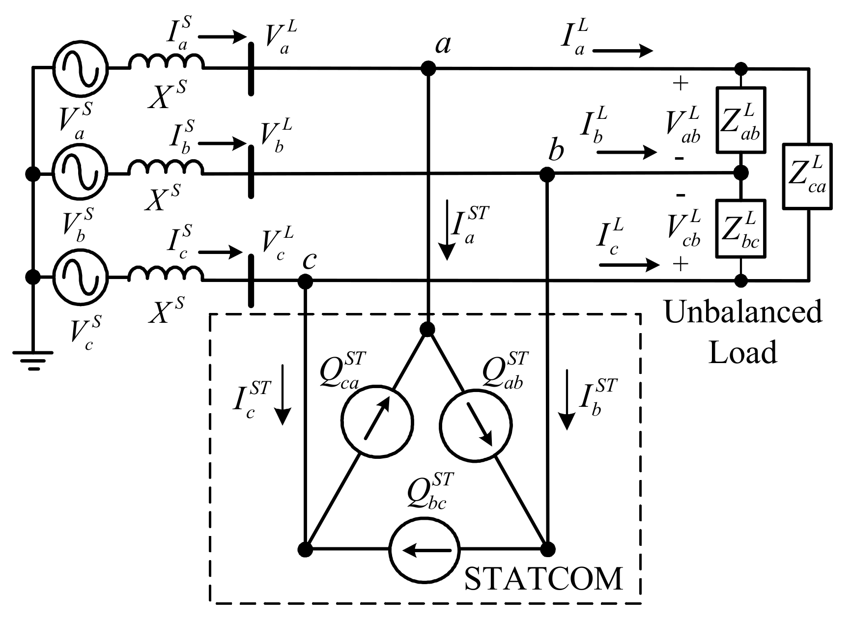
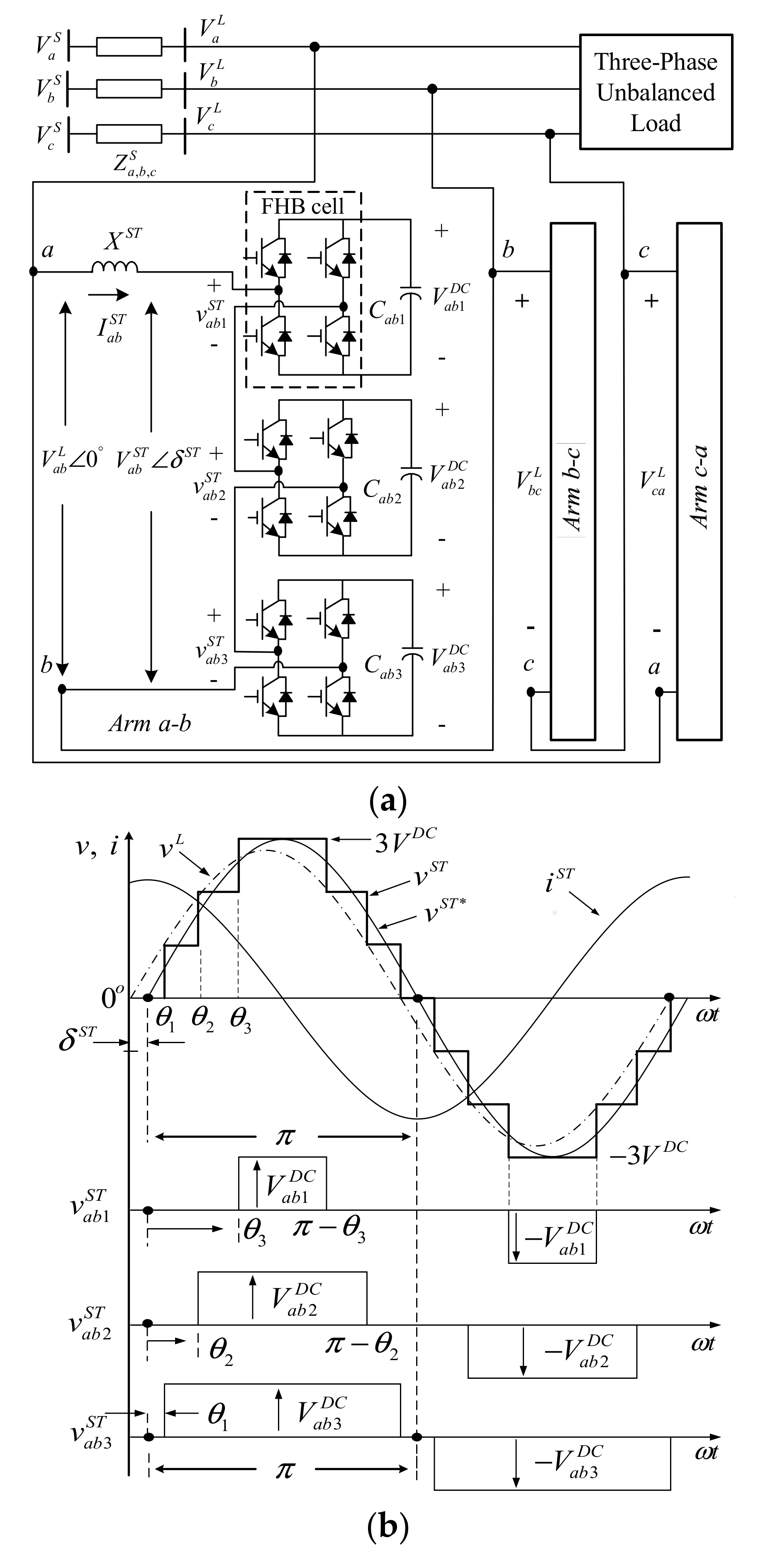
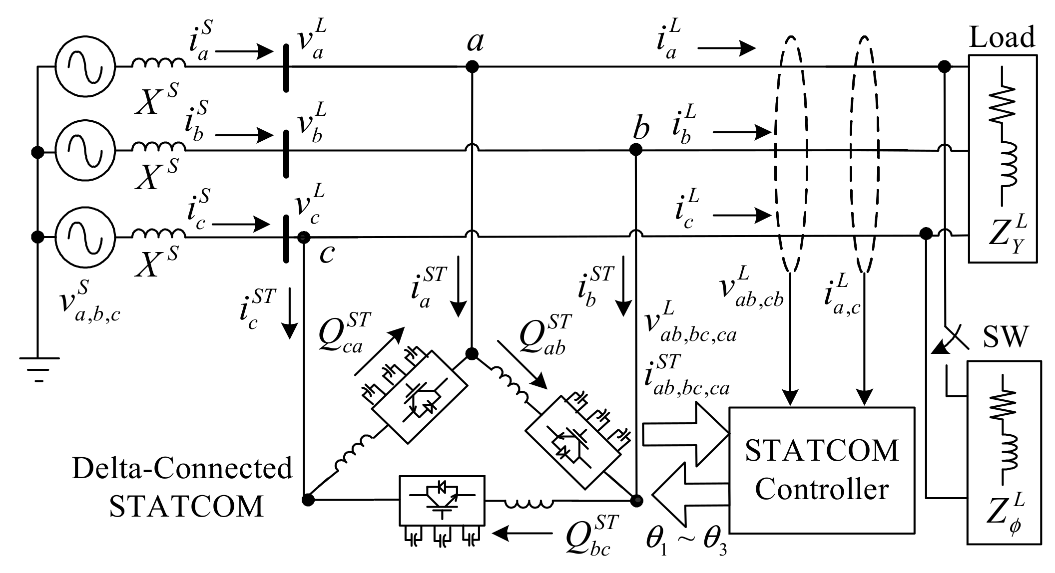
2. Operation of the STATCOM Main Circuit
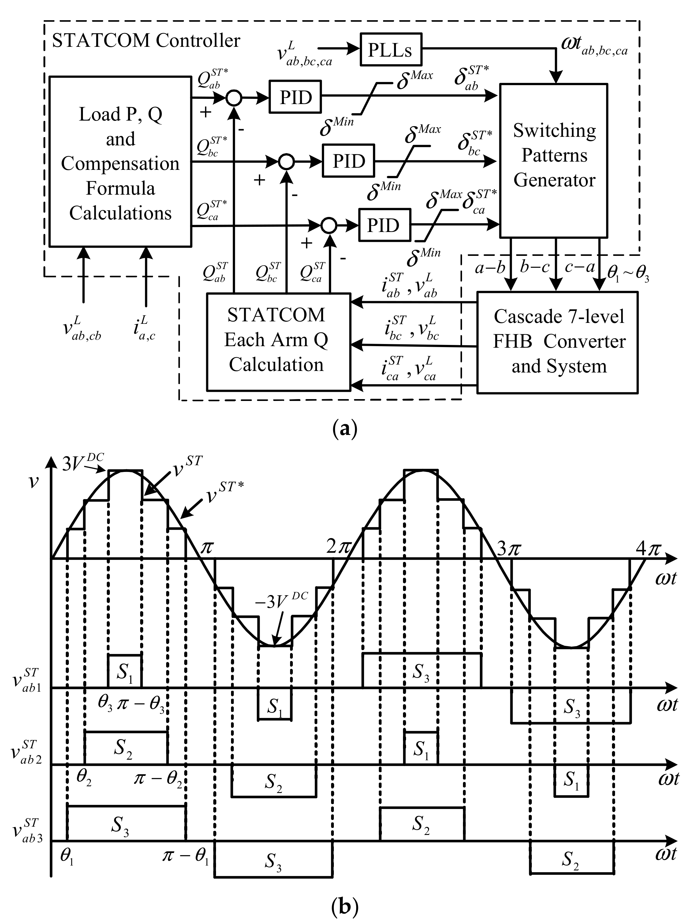
3. STATCOM Compensation Formula and Controller
3.1. The Proposed Compensation Formula
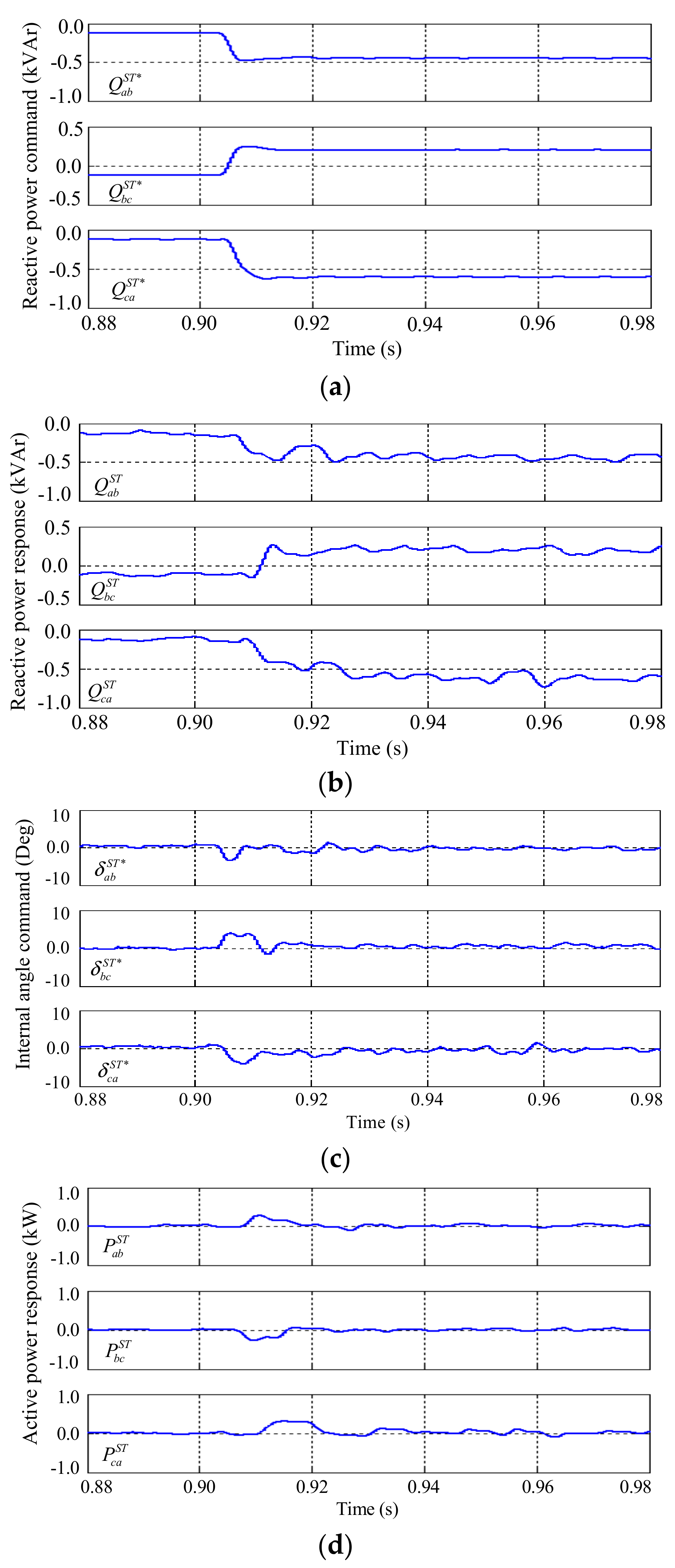
3.2. The Proposed STATCOM Controller
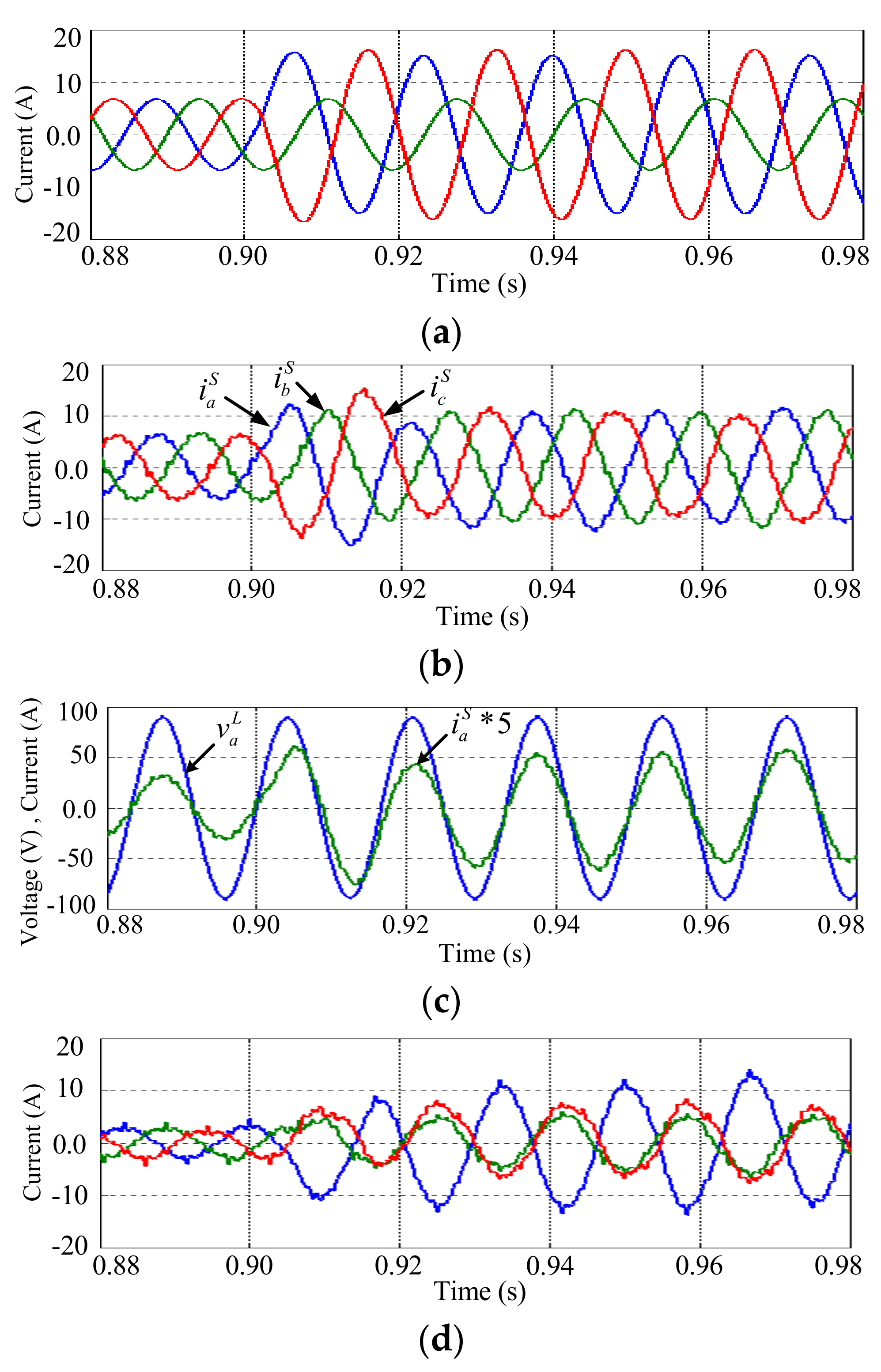
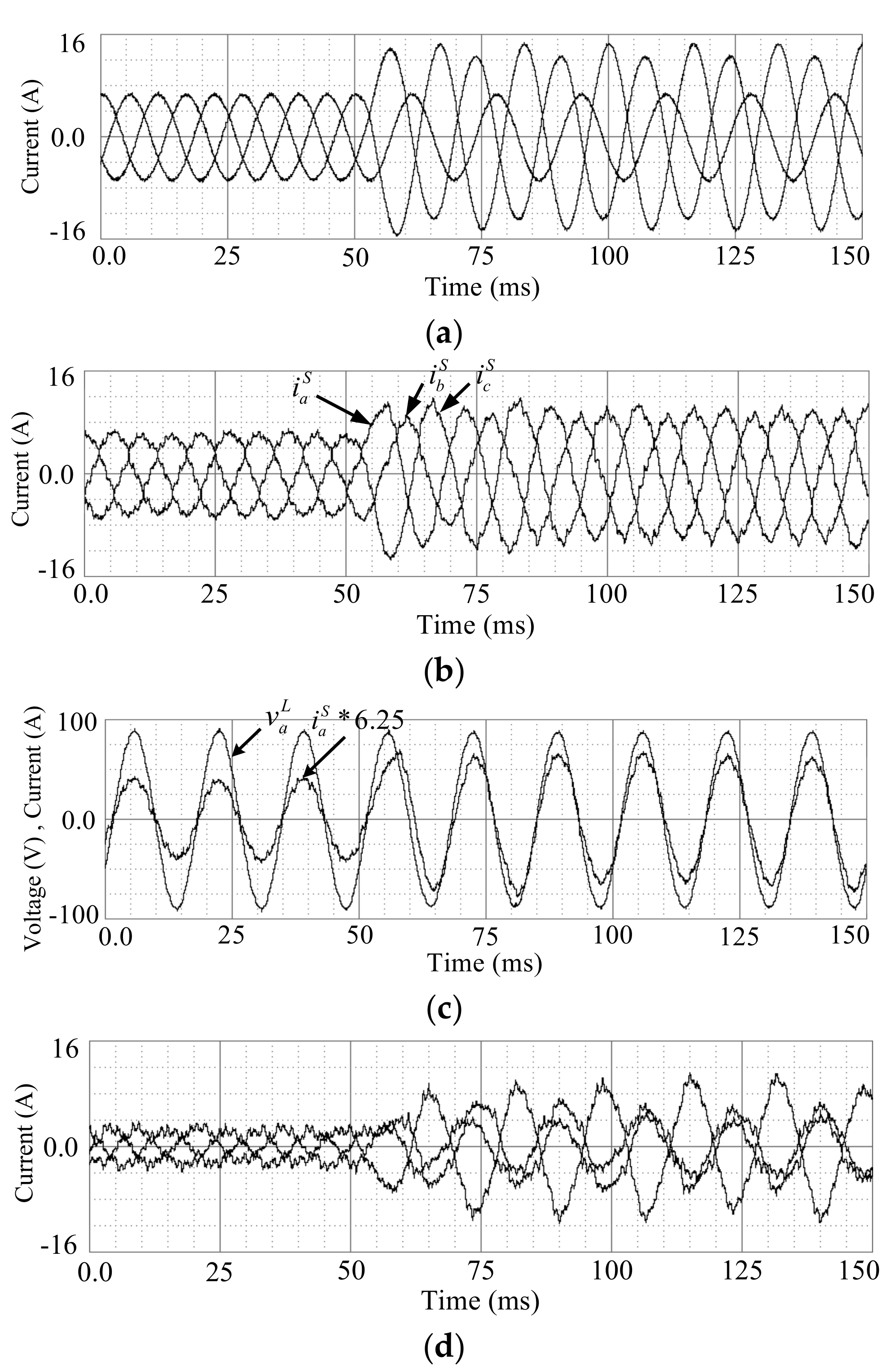
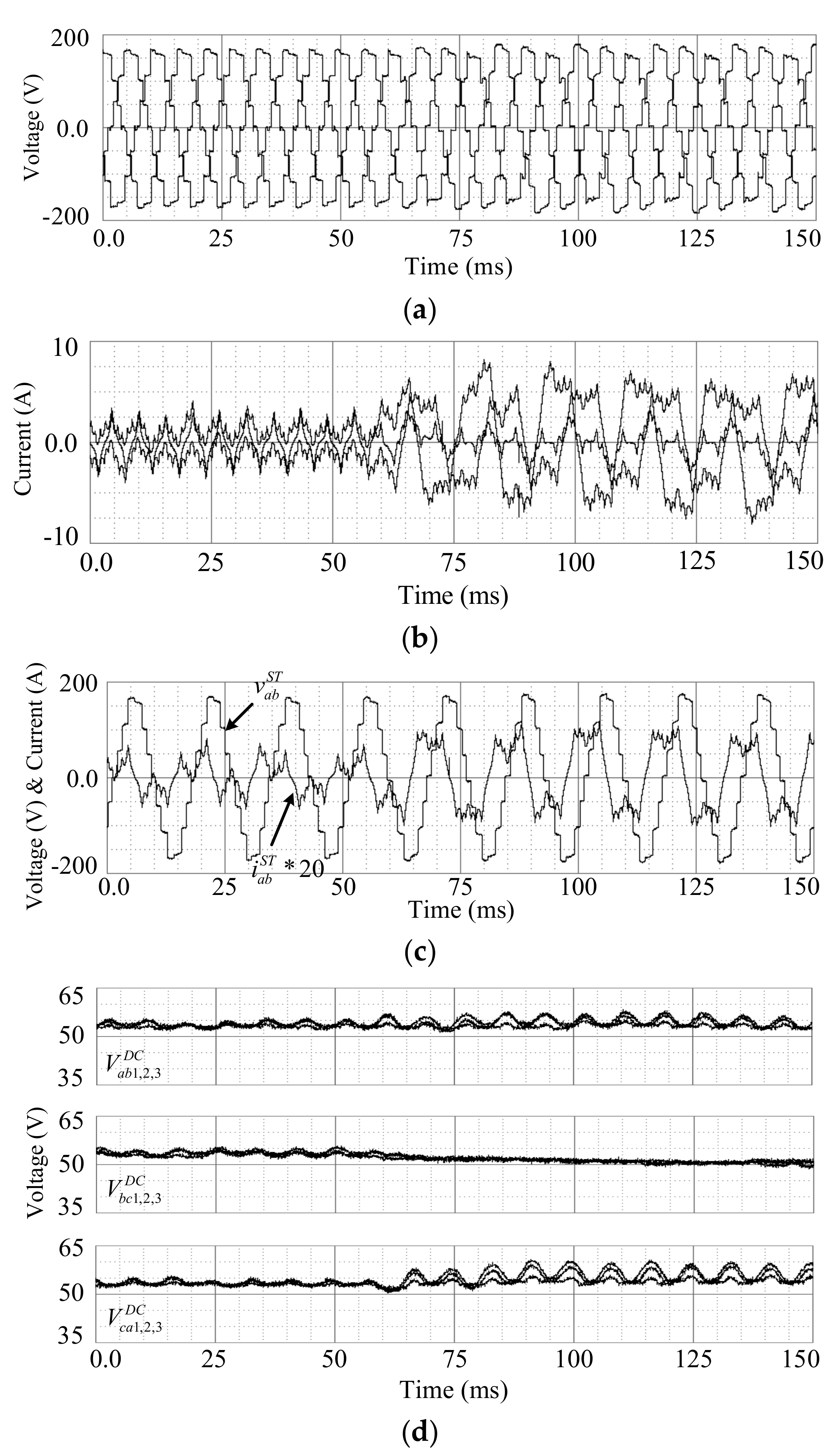
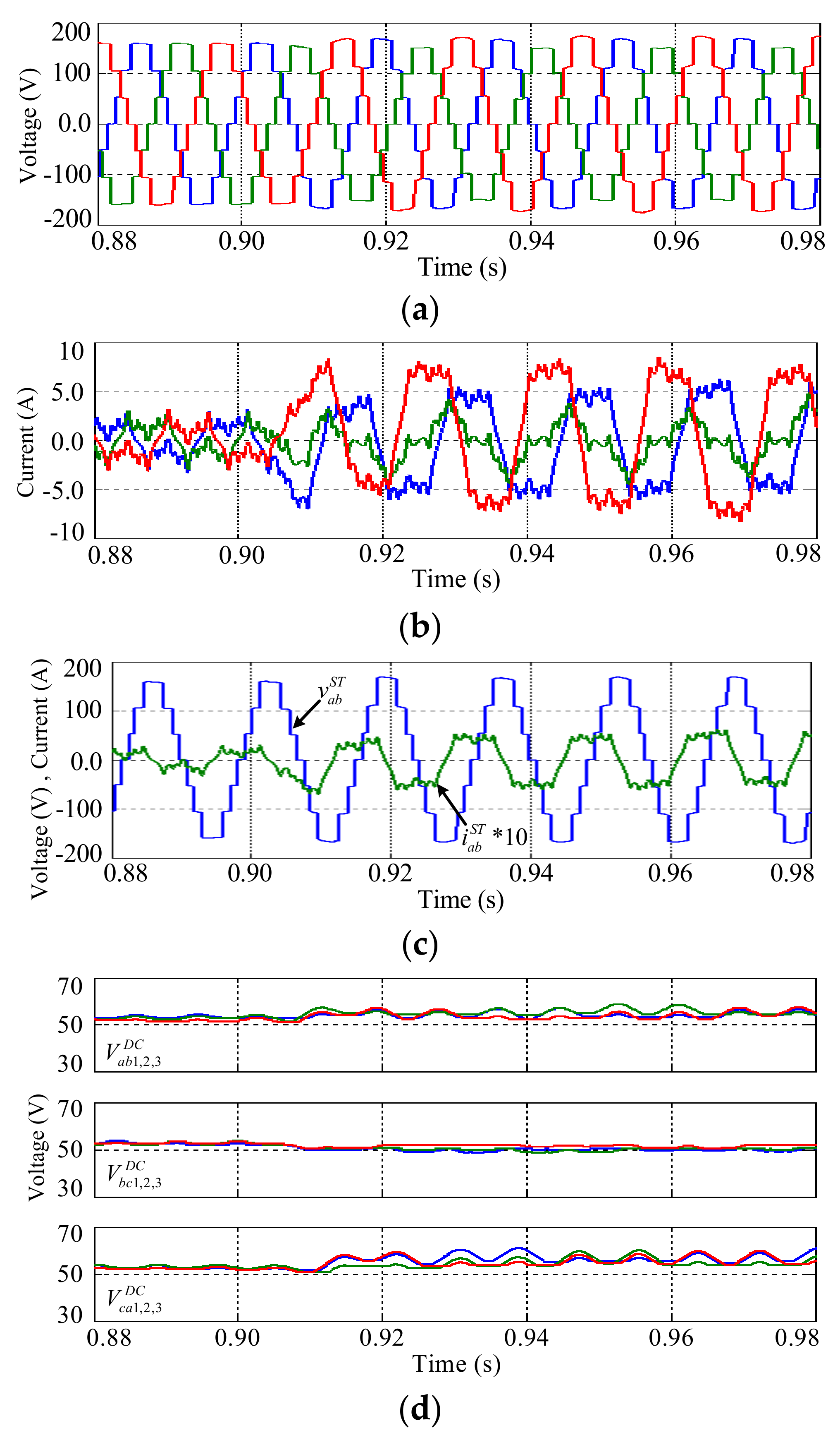
4. Simulation Results
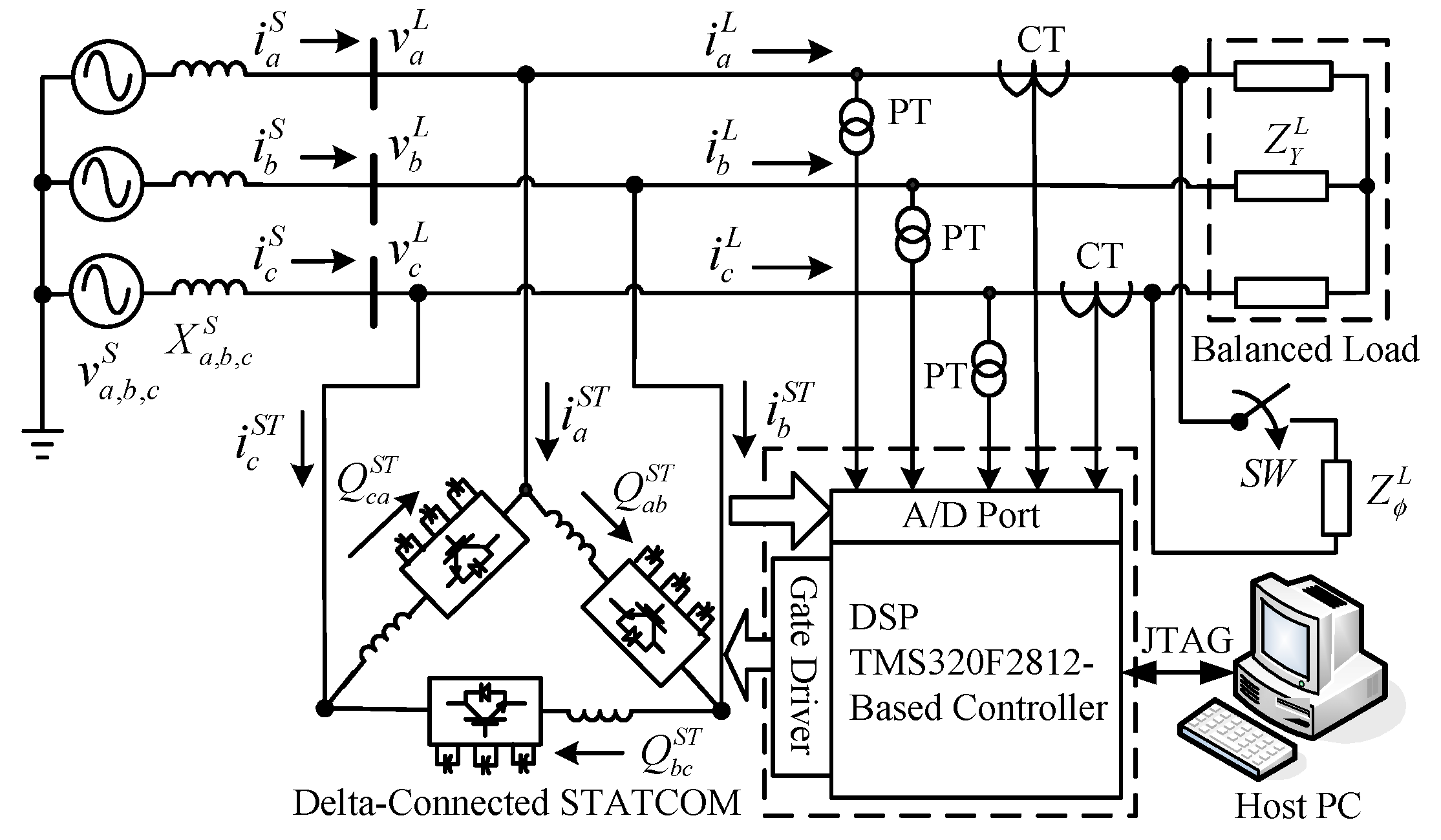
5. Hardware Test Results
6. Conclusions
Acknowledgments
Author Contributions
Conflicts of Interest
Nomenclature
| General | |
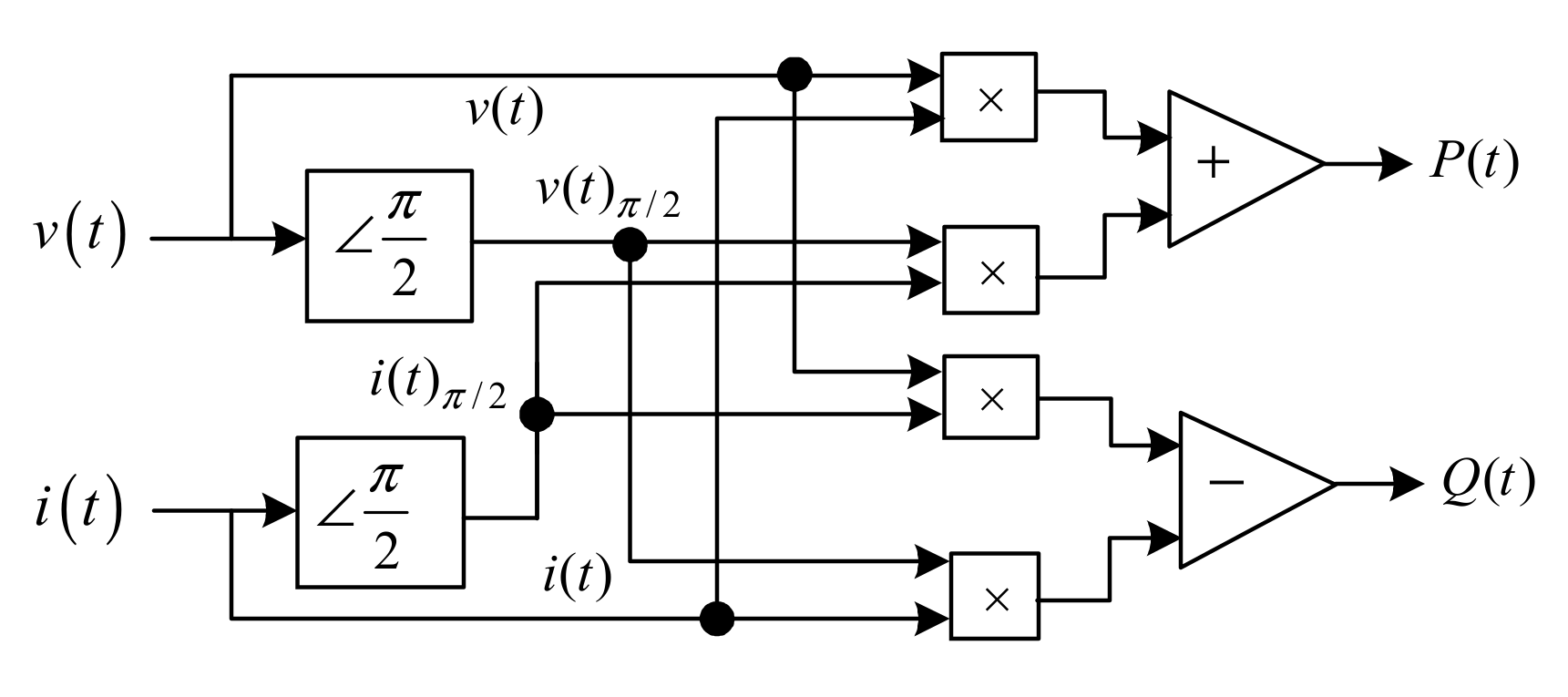
| active power | |
| reactive power | |
| instantaneous voltage | |
| instantaneous current | |
| internal angle | |
| voltage phasor | |
| current phasor | |
| ,, | switching angle |
| impedance | |
| reactance | |
| harmonic order | |
| amplitude of fundamental and harmonic components | |
| switching function | |
| Superscripts | |
| source | |
| load | |
| STATCOM | |
| STATCOM command | |
| dc link | |
| * | complex conjugate |
| Subscripts | |
| zero-, positive-, negative-component | |
| a, b, c phase | |
| a-b, b-c, c-a line | |
| three phase | |
| Y connection | |
| single phase |
Appendix A
Appendix B
References
- Xu, Y.; Tolbert, L.M.; Kueck, J.D.; Rizy, D.T. Voltage and current unbalance compensation using a static var compensator. IET Power Electron. 2010, 3, 977–988. [Google Scholar] [CrossRef]
- Miller, T.J.E. Reactive Power Control in Electric System; Wiley & Sons: New York, NY, USA, 1982. [Google Scholar]
- Gyugyi, L.; Otto, R.A.; Putman, T.H. Principles and applications of static, thyristor-controlled shunt compensators. IEEE Trans. Power Appar. Syst. 1978, 97, 1935–1945. [Google Scholar]
- Chen, J.H.; Lee, W.J.; Chen, M.S. Using a static var compensator to balance a distribution system. IEEE Trans. Ind. Appl. 1999, 35, 298–304. [Google Scholar] [CrossRef]
- Wang, J.; Fu, C.; Zhang, Y. SVC control system based on instantaneous reactive power theory and fuzzy PID. IEEE Trans. Ind. Electron. 2008, 55, 1658–1665. [Google Scholar] [CrossRef]
- Czarnecki, L.S.; Hsu, S.M.; Chen, G. Adaptive balancing compensator. IEEE Trans. Power Deliv. 1995, 10, 1663–1669. [Google Scholar] [CrossRef]
- Singh, B.; Saha, R.; Chandra, A.; Al-Haddad, K. Static synchronous compensators (STATCOM): A review. IET Power Electron. 2009, 2, 297–324. [Google Scholar] [CrossRef]
- Ghosh, A.; Ledwich, G. Load compensating DSTATCOM in weak AC systems. IEEE Trans. Power Electron. 2003, 18, 1302–1309. [Google Scholar] [CrossRef]
- Mishra, M.K.; Karthikeyan, K. A fast-acting DC-link voltage controller for three-phase DSTATCOM to compensate AC and DC loads. IEEE Trans. Power Electron. 2009, 24, 2291–2299. [Google Scholar] [CrossRef]
- Atalik, T.; Deniz, M.; Koc, E.; Gercek, C.O.; Gultekin, B.; Ermis, M.; Cadirci, I. Multi-DSP and -FPGA-based fully digital control system for cascaded multilevel converters used in FACTS applications. IEEE Trans. Ind. Inform. 2012, 8, 511–527. [Google Scholar] [CrossRef]
- Peng, F.Z.; Lai, J.S.; McKeever, J.W.; VanCoevering, J. A multilevel voltage-source inverter with separate DC sources for static VAr generation. IEEE Trans. Ind. Appl. 1996, 32, 1130–1138. [Google Scholar] [CrossRef]
- Lai, J.S.; Peng, F.Z. Multilevel converters-a new breed of power converters. IEEE Trans. Ind. Appl. 1996, 32, 509–517. [Google Scholar]
- Lee, C.K.; Leung, J.S.K.; Hui, S.Y.R.; Chung, H.S.H. Circuit-level comparison of STATCOM technologies. IEEE Trans. Power Electron. 2003, 18, 1084–1092. [Google Scholar] [CrossRef]
- Rodriguez, J.; Lai, J.S.; Peng, F.Z. Multilevel inverters: A survey of topologies, controls, and applications. IEEE Trans. Ind. Electron. 2002, 49, 724–738. [Google Scholar] [CrossRef]
- Peng, F.Z.; Lai, J.S. Dynamic performance and control of a static var generator using cascade multilevel inverters. IEEE Trans. Ind. Appl. 1997, 33, 748–755. [Google Scholar] [CrossRef]
- Maharjan, L.; Inoue, S.; Akagi, H. A transformerless energy storage system based on a cascade multilevel PWM converter with star configuration. IEEE Trans. Ind. Appl. 2008, 44, 1621–1630. [Google Scholar] [CrossRef]
- Sano, K.; Takasaki, M. A transformerless D-STATCOM based on a multivoltage cascade converter requiring no DC sources. IEEE Trans. Power Electron. 2012, 27, 2783–2795. [Google Scholar] [CrossRef]
- Gultekin, B.; Gercek, C.O.; Atalik, T.; Deniz, M.; Bicer, N.; Ermis, M.; Kose, K.N.; Ermis, C.; Koc, E.; Cadirci, I.; et al. Design and implementation of a 154-kV ±50-Mvar transmission STATCOM based on 21-level cascaded multilevel converter. IEEE Trans. Ind. Appl. 2008, 48, 1030–1045. [Google Scholar] [CrossRef]
- Gultekin, B.; Ermis, M. Cascaded multilevel converter-based transmission STATCOM: System design methodology and development of a 12 kV ±12 MVAr power stage. IEEE Trans. Power Electron. 2013, 28, 4930–4950. [Google Scholar] [CrossRef]
- Akagi, H. Classification, terminology, and application of the modular multilevel cascade converter (MMCC). IEEE Trans. Power Electron. 2011, 26, 3119–3130. [Google Scholar] [CrossRef]
- Peng, F.Z.; Wei, Q.; Dong, C. Recent advances in multilevel converter/inverter topologies and applications. In Proceedings of the 2010 International Power Electronics Conference, Sapporo, Japan, 21–24 June 2010; pp. 492–501. [Google Scholar]
- Liu, Z.; Liu, B.; Duan, S.; Kang, Y. A novel DC capacitor voltage balance control method for casca1de multilevel STATCOM. IEEE Trans. Power Electron. 2012, 27, 14–27. [Google Scholar] [CrossRef]
- Peng, F.Z.; Wang, J. A universal STATCOM with delta-connected cascade multilevel inverter. In Proceedings of the 2004 IEEE 35th Annual Power Electronics Specialists Conference, Aachen, Germany, 20–25 June 2004; Volume 5, pp. 3529–3533. [Google Scholar]
- Chang, W.N.; Liao, C.H. Real-time load compensation by using a cascaded multilevel inverter-based STATCOM. In Proceedings of the 2011 IEEE Ninth International Conference on Power Electronics and Drive Systems, Singapore, 5–8 December 2011; pp. 840–846. [Google Scholar]
- Chang, W.N.; Liao, C.H.; Wang, P.L. Unbalanced load compensation in three-phase power system with a current-regulated DSTATCOM based on cascade modular h-bridge converter. J. Mar. Sci. Technol. 2016, 24, 484–492. [Google Scholar]
- Song, Q.; Liu, W.; Yuan, Z. Multilevel optimal modulation and dynamic control strategies for STATCOMs using cascaded multilevel inverters. IEEE Trans. Power Electron. 2007, 22, 1937–1946. [Google Scholar] [CrossRef]
- Shi, Y.; Liu, B.; Duan, S. Eliminating DC current injection in current-transformer-sensed STATCOMs. IEEE Trans. Power Electron. 2013, 28, 3760–3767. [Google Scholar] [CrossRef]
- Hagiwara, M.; Maeda, R.; Akagi, H. Negative-sequence reactive-power control by a PWM STATCOM based on a modular multilevel cascade converter (MMCC-SDBC). IEEE Trans. Ind. Appl. 2012, 48, 720–729. [Google Scholar] [CrossRef]
- Du, S.; Liu, J.; Lin, J.; He, Y. A novel DC voltage control method for STATCOM based on hybrid multilevel h-bridge converter. IEEE Trans. Power Electron. 2013, 28, 101–111. [Google Scholar] [CrossRef]
- Wu, P.H.; Chen, H.C.; Chang, Y.T.; Cheng, P.T. Delta-connected cascaded H-bridge converter application in unbalanced load compensation. IEEE Trans. Ind. Appl. 2017, 53, 1254–1262. [Google Scholar] [CrossRef]
- Schauder, C.; Menhta, H. Vector analysis and control of advanced static VAR compensators. IEE Proc. C Gener. Transm. Distrib. 1993, 140, 299–306. [Google Scholar] [CrossRef]
- Sirisukprasert, S.; Lai, J.S.; Liu, T.H. Optimum harmonic reduction with a wide range of modulation indexes for multilevel converters. IEEE Trans. Ind. Electron. 2002, 49, 875–881. [Google Scholar] [CrossRef]
- Liu, Y.; Hong, H.; Huang, A.Q. Real-time calculation of switching angles minimizing THD for multilevel inverters with step modulation. IEEE Trans. Ind. Electron. 2009, 56, 285–293. [Google Scholar] [CrossRef]
- Chang, W.N.; Pon, W.H.; Yeh, K.D. Digital design and implementation of fast power data detector. In Proceedings of the IEEE International Conference of Power Electronics and Drive Systems (PEDS’2001), Denpasar, Indonesia, 25–25 October 2001; Volume 200, pp. 623–627. [Google Scholar]
- Peng, F.Z.; McKeever, J.W.; Adams, D.J. A power line conditioner using cascade multilevel inverters for distribution systems. IEEE Trans. Ind. Appl. 1998, 34, 1293–1298. [Google Scholar] [CrossRef]
- Tolbert, L.M.; Peng, F.Z.; Habetler, T.G. Multilevel converters for large electric drives. IEEE Trans. Ind. Appl. 1999, 35, 36–44. [Google Scholar] [CrossRef]
- Rashid, M.H. Power Electronics Handbook: Devices, Circuits, and Applications, 3rd ed.; Elsevier Inc.: Oxford, UK, 2011; p. 1049. [Google Scholar]
- IEEE Recommended Practices and Requirements for Harmonic Control in Electrical Power Systems; IEEE Std. 519-1992; IEEE: New York, NY, USA, 1993.


| Source | ||||||
| Load | ||||||
| STATCOM | ||||||
| Harmonic Orders | 1st (A) | 3rd (A) | 5th (A) | 7th (A) | 9th (A) | 11th (A) | 13th (A) | THD (%) | |
|---|---|---|---|---|---|---|---|---|---|
| Phases | 3.79 | 0.88 | 0.01 | 0.03 | 0.36 | 0.09 | 0.07 | 26.27 | |
| 1.55 | 0.64 | 0.03 | 0.02 | 0.32 | 0.10 | 0.08 | 51.51 | ||
| 4.96 | 1.03 | 0.06 | 0.03 | 0.31 | 0.11 | 0.06 | 23.19 | ||
| 7.57 | 0.16 | 0.06 | 0.07 | 0.05 | 0.17 | 0.11 | 4.94 | ||
| Lines | 3.24 | 0.27 | 0.04 | 0.03 | 0.09 | 0.18 | 0.11 | 12.6 | |
| 4.44 | 0.42 | 0.04 | 0.04 | 0.10 | 0.15 | 0.13 | 11.23 | ||
© 2017 by the authors. Licensee MDPI, Basel, Switzerland. This article is an open access article distributed under the terms and conditions of the Creative Commons Attribution (CC BY) license (http://creativecommons.org/licenses/by/4.0/).
Share and Cite
Chang, W.-N.; Liao, C.-H. Design and Implementation of a STATCOM Based on a Multilevel FHB Converter with Delta-Connected Configuration for Unbalanced Load Compensation. Energies 2017, 10, 921. https://doi.org/10.3390/en10070921
Chang W-N, Liao C-H. Design and Implementation of a STATCOM Based on a Multilevel FHB Converter with Delta-Connected Configuration for Unbalanced Load Compensation. Energies. 2017; 10(7):921. https://doi.org/10.3390/en10070921
Chicago/Turabian StyleChang, Wei-Neng, and Ching-Huan Liao. 2017. "Design and Implementation of a STATCOM Based on a Multilevel FHB Converter with Delta-Connected Configuration for Unbalanced Load Compensation" Energies 10, no. 7: 921. https://doi.org/10.3390/en10070921
APA StyleChang, W.-N., & Liao, C.-H. (2017). Design and Implementation of a STATCOM Based on a Multilevel FHB Converter with Delta-Connected Configuration for Unbalanced Load Compensation. Energies, 10(7), 921. https://doi.org/10.3390/en10070921