Harmonic Modelling of the Wind Turbine Induction Generator for Dynamic Analysis of Power Quality
by
 , and
, and
Héctor García
1,2,*, 
Juan Segundo
3,
Osvaldo Rodríguez-Hernández
2,
Rafael Campos-Amezcua
2 and
Oscar Jaramillo
2 1
Consejo Nacional de Ciencia y Tecnología (CONACYT), 03940 México, Mexico
2
Renewable Energies Institute, National Autonomous University of Mexico, A.P. 34, 62580 Temixco, Mor., México, Mexico
3
Faculty of Engineering, Autonomous University of San Luis Potosí, Manuel Nava No. 8, San Luis Potosí S.L.P., 78290 México, Mexico
*
Author to whom correspondence should be addressed.
Energies 2018, 11(1), 104; https://doi.org/10.3390/en11010104
Submission received: 30 November 2017
/
Revised: 21 December 2017
/
Accepted: 28 December 2017
/
Published: 3 January 2018
(This article belongs to the Special Issue Wind Generators Modelling and Control)
Abstract
:Given the increasing integration of wind-based generation systems into the electric grid, efforts have been made to deal with the problem of power quality associated with the intermittent nature of these systems. This paper presents a new modelling approach oriented towards harmonic distortion analysis of the induction machine for wind power applications. The model is developed using companion harmonic circuit modelling, which is a natural approach for analysis of the adverse effects of harmonic distortion in electric power systems, and represents an easier solution method than the well known dynamic harmonic domain, since it solves algebraic equations instead of state-space differential equations. The structure of the companion circuits simplifies both the formulation and solution for power systems with wind-based generation systems. This approach is especially useful for analysis of the harmonic interaction in transient and steady states between the wind power generator and the power system, whose interconnection is made through electronic converters. The proposed model allows us to compute the dynamics of the wind turbine, which are influenced by disturbances such as changes in the wind velocity, voltage fluctuations, electric waveform distortion, and mechanical vibrations, among other factors. Moreover, the cross-coupling between harmonic components at different frequencies is considered. The proposed model represents an integral framework of the electrical and mechanical subsystems of a wind turbine, allowing for analysis of the interactions between them, and understanding power quality degradation behaviour as well as causes and consequences, while also giving useful information on the field of simulation and control. To test the performance of the proposed model, a test power system is used to obtain the behaviour of a wind turbine induction generator in response to typical power quality disturbances, i.e., harmonic distortion, and voltage sags and swells. Then, the dynamics of the variables considering their harmonic interactions are analysed.
1. Introduction
Climate change has led to a continuous worldwide search for knowledge related to cleaner sources of energy. The goal is not only to avoid emissions of CO2 caused by the combustion of fossil fuels, but also to find a wide range of reliable renewable sources of electricity capable of satisfying the increasing global electricity demand and contributing to sustainable development. Wind power has become one of the most popular options for substituting fossil fuels, due to its competitive generation costs and technological maturity. In 2016, the capacity installed around the world reached 435 GW, and, in 2020, this figure is expected to reach 1000 GW [1]. The sustained growth of wind power has led to grid connections to larger wind energy conversion systems, and as such the intermittent nature of wind power has been an object of study [2].
In wind turbines, the simplest form of the alternating current generator used is the induction generator; in fact, this is the most common electric generator in installed wind power plants. The simplest form of an induction generator is the squirrel cage rotor (SCIG); this machine has proven its worth due to its qualities, such as robustness, low cost, and simplicity when it is directly connected to the network. However, such a direct interconnection with the grid may allow speed variations only in a very narrow range, and therefore, wind turbine utilization is limited, as well as its electric power output. Another major drawback with SCIG is the requirement of reactive power, and consequently, the need for an external reactive power compensator [3,4]. Induction generators are also constructed using wound rotors (WRIG); wound rotors are externally accessible through slip rings, and it is possible to control the electrical torque and thus the slip. Power electronics modules can be used to control the rotor windings. This allows the operation of the induction machine as a doubly-fed induction generator (DFIG) [5].
The integration of large wind-based generation systems into the grid can provide large amounts of electric power, but there are technical issues concerning the stability and power quality of the electricity supplied due to wind intermittency and variability. In addition, the electronic power devices used for their integration, like static compensators (STATCOM), and voltage source converters (VSC)-based components, among others, play a major role in power quality improvement [6,7]. Particular attention must be paid to the compensation of reactive power, harmonic distortion, and voltage fluctuation (sags and swells) during interconnected operation. Adverse effects of harmonic distortion on wind power generation include, for instance, interference with communication, improper operation of control and protection systems, reduction of the equipment life span, mechanical shaft failures, and additional losses in the power system [8]. The harmonic interaction between the wind generators and the power network has led to some power quality and stability issues, and, recently, this topic has attracted much attention. For instance, prior works [9,10] deal with the resonance issues in doubly-fed induction generator (DFIG)-based wind power plants tied to a weak network. This resonance problem in wind power systems is also studied in [11] using sensitivity analysis. A more recent work [12] shows and analyses in detail the interaction of harmonic stability and resonance problems with the harmonic components, passive elements, and control systems. These previous works highlight the relevance of the proposed harmonic model for further analyses since this model is time-invariant and every harmonic component of every state variable of the original time domain model is a state variable in this harmonic framework.
Power quality is not only influenced by the electrical components of the wind turbine, but also by mechanical components and their interactions. In general, the drive train of a horizontal axis wind turbine consists of three main parts: a rotor, a gearbox, and an electric generator. Vibrations occurring in any of these parts are transmitted to the others through relative movements between the mechanical components, such as shafts, gears, couplings, bearings, etc. Some studies present the effects of disturbances caused to both the wind turbine rotor and the electrical network on the power quality in electrical systems. The authors of [13] present the spectral effects that stator supply harmonics can induce in wound rotor and doubly-fed induction generators. However, the effects of disturbances originating in the generator (electrical network) on the mechanical elements are commonly not considered; this is mainly because the wind and mechanical operation disturbances play a much more important role in stress analysis of mechanical components than the electrical network disturbances. It is important to notice that, unlike electrical disturbances (typically s), electrical failures (s) do have a critical effect on the structural analysis of the drive train components [14].
With regards to the above mentioned research, studies on the mathematical modelling including the mechanical and electric systems for performing analysis in the fields of control, power smoothing, electrical fluctuations, harmonics, and flicker [15,16] are necessary. The harmonic effect modelling in wind induction generators is reported in [17,18], using the principles of generalised harmonic analysis and complex conductor distribution to develop a method for calculating circuit’s self and mutual inductance for windings. The authors of [19] propose a steady-state model for the doubly-fed induction machine for harmonic studies that models a set of equations to give the current response of the DFIG when it is fed with sinusoidal and non-sinusoidal voltage sources. The development of appropriate models in order to compute fast, accurate, and reliable results so as to understand, control, and analyse the harmonic interaction between wind turbine generators and the utility system is mandatory. In particular, power systems, including wind turbine generators, are non-linear and discontinuous because of the power electronic converters, the control schemes, and the non-linear nature of the induction generators and the electric power components. These difficulties are common in all power systems with power electronic converters and electric machines. An approach to modelling all the components (i.e., the power system, power electronics, electric generator and wind turbine drive train) in the same system, while also considering the cross-coupling between the harmonic content, would increase the accuracy and reliability of the obtained results.
In this contribution, a model of a wind turbine generator is proposed that preserves all the advantages of the dynamic harmonic domain domain DHD, (also known in the literature as the extended harmonic domain, dynamic phasor, or shifted frequency), but is so much simpler since algebraic equations are proposed instead state-space differential equations, as is common in DHD. This also allows the model to be included in larger system simulations than those modelled in the DHD. Specifically, a companion harmonic circuit model (CHCM) of the induction machine for wind power applications is presented. It should be noticed that the DHD is a natural frame of reference for dynamic power electronics modelling. Then, the proposed model brings a complete description of the harmonic interaction between the power system and wind turbine generators both in the transient state and in the steady state. On the other hand, the proposed approach includes the coupling between the mechanical wind turbine drive train and the induction generator, allowing the analysis of the adverse effects of the harmonic waveform distortion on the mechanical oscillations and vice versa. That is, the introduced model includes the interaction between the electrical and mechanical parts of the wind turbine generator, i.e., the electromagnetic torque, the wind turbine torque, and the mechanical power extracted from the wind, among others. In addition, an analysis of the effects of harmonic distortion on the power requirements of the induction machine is given.
This paper is organized as follows: First, the frameworks of the electric and mechanical subsystems selected to integrate the proposed model are presented. Second, the theoretical model is analysed in a typical situation to verify the responses of the subsystems in steady and transient states. Finally, the main conclusions are presented.
2. Companion Harmonic Circuit Modelling
The companion harmonic circuit modelling approach is based on the combination of two well-known methodologies. The DHD and the numerical approximation together form a simple but powerful approach for complete harmonic analysis under both transient state and steady-state conditions of power systems [20]. The DHD is a formulation based on orthogonal bases, operational matrices, Fourier series, and approximation of operators. The main idea behind the DHD is that a function, , can be approximated by the time-dependent Fourier series coefficients,
The complex Fourier coefficients are a function of the time, and each coefficient is calculated by
where , and T is the fundamental period of time under consideration. Equation (2) computes the time evolution of the harmonics as a window of length T that slides over the waveform . In [20], it is well explained that the state-space equation can be represented in the DHD by
The vector is the state variable whose components are the harmonics coefficients of the function ; is the input vector of the system whose components are the harmonic coefficients of . and are Toeplitz matrices whose components are the harmonic coefficients of and , respectively. is a differentiation matrix given by the square diagonal matrix, The expression in Equation (3) gives the dynamic evolution of the harmonic coefficients of the periodic variable . In addition, the steady-state response is given when the derivative of the state vector is equal to zero, i.e., . In steady-state, the harmonics of the dynamic variable are time-invariant; then, the steady state is given by,
Equation (4) establishes the conditions for steady state, and then its solution can be used as an initial condition when solving Equation (3). This characteristic is very important since in many cases it is difficult to obtain a steady-state solution of a dynamic non-linear system [20,21].
From the numerical integration point of view, in the DHD, a differential equation can be approximated by a resistive circuit associated with the integration algorithm [22], henceforth called the companion harmonic circuit model. The resulting algebraic equation leads to a Norton equivalent circuit comprised for an admittance matrix and a current source, with the following equivalent equation,
Equation (5) presents the basic structure of the CHCM. In general, the admittance matrix is time-varying but it is constant in the particular case of linear systems [21].
It should be noted that the use of CHCM preserves the qualities of the DHD but facilities their application and solution. Up to this point, the basic methodology of the time-frequency modelling used in the development of the proposed model has been presented. Next, the wind turbine modelling is explained in two separate sections: Section 3 presents the induction machine modelling, and Section 4 the drive train wind turbine modelling.
3. Induction Machine Model
The time domain differential equations system that represents the dynamics of an induction machine in terms of machine variables may be expressed as [23]:
All the parameters in Equation (6) represent a three-phase system, and the s and r subscripts denote variables and parameters associated with the stator and rotor circuits, respectively. For a magnetically linear system, the flux linkages may be expressed as
The winding inductances are presented in Appendix A.
The substitution of Equation (7) into Equation (6) yields the state-space equation that represents the dynamic behaviour of the induction machine in terms of machine electrical variables.
Applying the dynamic harmonic domain methodology to Equation (8), and then applying a numerical integration rule, the companion harmonic circuit model in the Norton equivalent form is obtained as shown in Equation (9). The detailed procedure of the development of the CHCM of the induction machine is presented in Appendix A.
The description of and is also presented in Appendix A. Notice that the time-varying nature of the complex matrix is due to the rotor angular position, and the variables for the stator and rotor are all included in Equation (9). A graphical representation of the CHCM for the induction machine is shown in Figure 1, where the phase inductances and sources are given by the time-varying complex inductance matrix , and the harmonic current source , respectively. Note that Equation (9) can represent both induction machines: the wound rotor or squirrel cage rotor.
On the other hand, the electromagnetic torque equation in machine variables is expressed in the harmonic domain as
where p is the number of poles of the machine, and the derivative matrix is given by
Each element in the above equation is a square sub-matrix with Toeplitz structure. Then, for a typical electric power system with dominant fundamental component and odd harmonics, a dominant direct current term and even harmonics in the electromagnetic torque are expected.
Steady-State Induction Machine Model
One of the advantages of the use of the dynamic harmonic domain is its performance on steady-state calculation [20]. Applying this property of the DHD, the following model that describes the steady state for the induction machine is obtained,
Notice that the solution of Equation (11) requires the steady-state of the mechanical variables and , since these values are required for the calculation of the admittance matrix.
The mechanical variables needed as input for the solution of the CHCM in Equations (9) and (11) could be obtained from several sources: the solution of mathematical equations, databases, and measurements of actual equipment, among others. The next section presents the modelling of the wind turbine drive train in order to complete the coupling between the mechanical and electrical subsystems in the wind-based generation system.
4. Wind Turbine Aerodynamic Model
The mathematical model used in this contribution to describe the relationship between the wind speed and the mechanical power extracted from the wind is [24,25].
where is the extracted power from the wind (watts), is the air density (kg/m3), is the area covered by the wind turbine rotor (m2), is the wind speed (m/s), and is known as the coefficient of performance or power coefficient, which is a function of the tip speed ratio , and the blade pitch angle (). The power coefficient is calculated as,
and the tip speed ratio is defined as,
The values of coefficients to depend on the wind turbine design. Numerical estimations for wind turbines designs are given in [26].
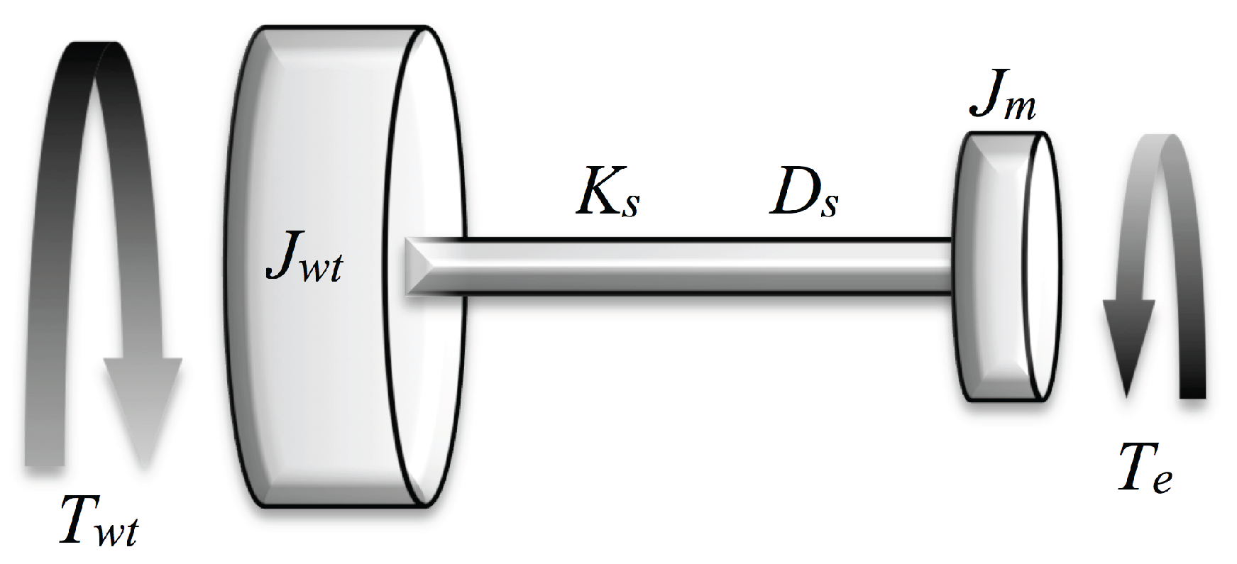
A two-mass model is shown in Figure 2. This model can be used to represent the behaviour and connection of the wind turbine with the induction machine. The major sources of inertia in this system lie in the turbine and in the generator rotors. The tooth wheels of the gearbox contribute only a relatively small fraction [26]. Hence, the mechanical system model can be represented by two masses connected by a shaft. The torque equations describing the mechanical behaviour of this system in the time domain are,
where is the aerodynamic torque (N·m); is the electromagnetic torque (N·m); and are the inertia constants (kg·m2) of the wind turbine and the induction machine, respectively; is the angular displacement between the two ends of the shaft; and are the frequency of the wind turbine and the induction machine rotor, respectively; is the damping coefficient (N·m s/rad); and is the shaft stiffness (N·m/rad).
Applying the CHCM methodology to Equation (15) yields the model for the harmonic analysis of the two-mass drive train.
The detailed procedure for the development of the CHCM of the two-mass drive train is presented in the Appendix B.
Finally, the turbine torque is obtained from the extracted power as:
Equation (16) computes the dynamic behaviour of the harmonic content of the speed for both the wind turbine and the induction generator.
The simultaneous solution of CHCMs in Equations (9) and (16) for the electrical and mechanical subsystems, respectively, allows for a complete analysis of the wind turbine dynamics, including the response to distorted electrical signals, disturbances, failures, and wind velocity variations. The next section presents an analysis of a wind turbine induction generator with respect to the effects of typical power quality disturbances.
5. Performance of the Proposed Model
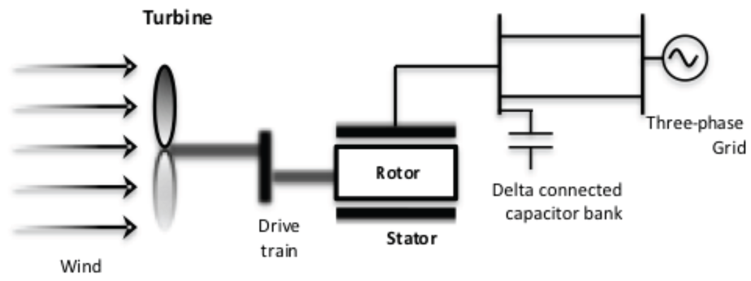
To demonstrate the performance of the proposed model, the test system shown in Figure 3 was used to analyse the behaviour of a wind turbine induction generator (WTIG) under typical power quality disturbances, and, then, analyse the dynamics of the variables considering their harmonic interaction. The test system consists of a wind turbine SCIG connected to a power system through two lines; for reactive power compensation a capacitor bank is also connected to the terminals of the induction generator. Notice that the proposed model includes the mechanical and electrical subsystems in the wind turbine generator, and then it is possible test perturbations or faults from both sides. For this study, typical cases are considered. From the wind turbine side, a change in the wind velocity (using a ramp) from 15 m/s to 11 m/s is tested; please note that perturbations or mechanical vibrations can be included. From the electrical system side, two perturbations are tested, a voltage sag and a voltage swell; perturbations were arbitrarily defined but within power quality definitions. For example, sag and swell definitions consider variations of between 10% and 90%, with a duration ranging from a half-cycle to one minute [27], while [28] considers a maximum duration of a few seconds. Therefore, the tested sag and swell were of in magnitude, with a duration of 30 cycles. At the point of common coupling, the power system presents typical harmonic voltage distortion associated to a six-pulse VSC-based system connected to the power network; as is well explained in [29], these are the negative and positive sequence harmonic multiples of six, i.e., the 5th, 7th, 11th, 13th, 17th, etc. At the presented analysis, the magnitudes are V, V, V, V and V for each harmonic, respectively, and a total harmonic distortion (THD) of 12%.
The parameters of the 900 kW wind turbine were taken from [30], and are presented in Table 1. In this reference, some results were found with respect to the real power and the angular speed, which can be used to validate the results obtained with the proposed model.
5.1. Mechanical Response
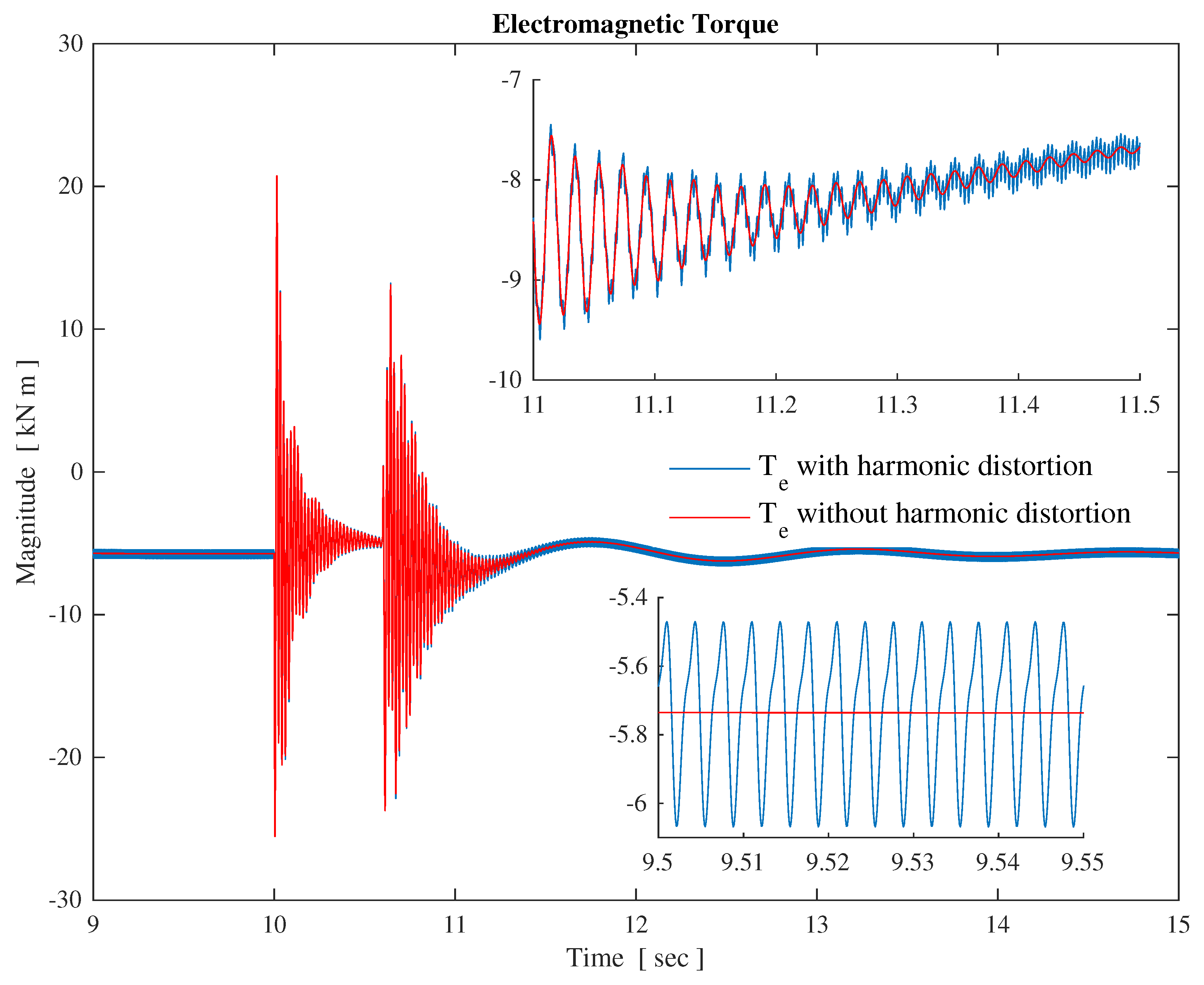
The behaviour of the electromagnetic torque is shown in Figure 4 to illustrate the importance of harmonic analysis in distorted systems. To obtain these results two cases were simulated: the voltage sag with harmonic distortion as previously mentioned, and without harmonic distortion. The graphics clearly show the effect of the harmonics introduced by the electrical system on the mechanical behaviour of the WTIG. For example, at steady-state without harmonic distortion, the electromagnetic torque has a constant magnitude, which means a “soft operation”. However, with harmonic distortion, significant oscillations appear, which can physically be observed as mechanical vibrations. In the transient stage, both cases present oscillations, but it is clear that with harmonic distortion the transient oscillations are meaningful, with a ripple of almost .
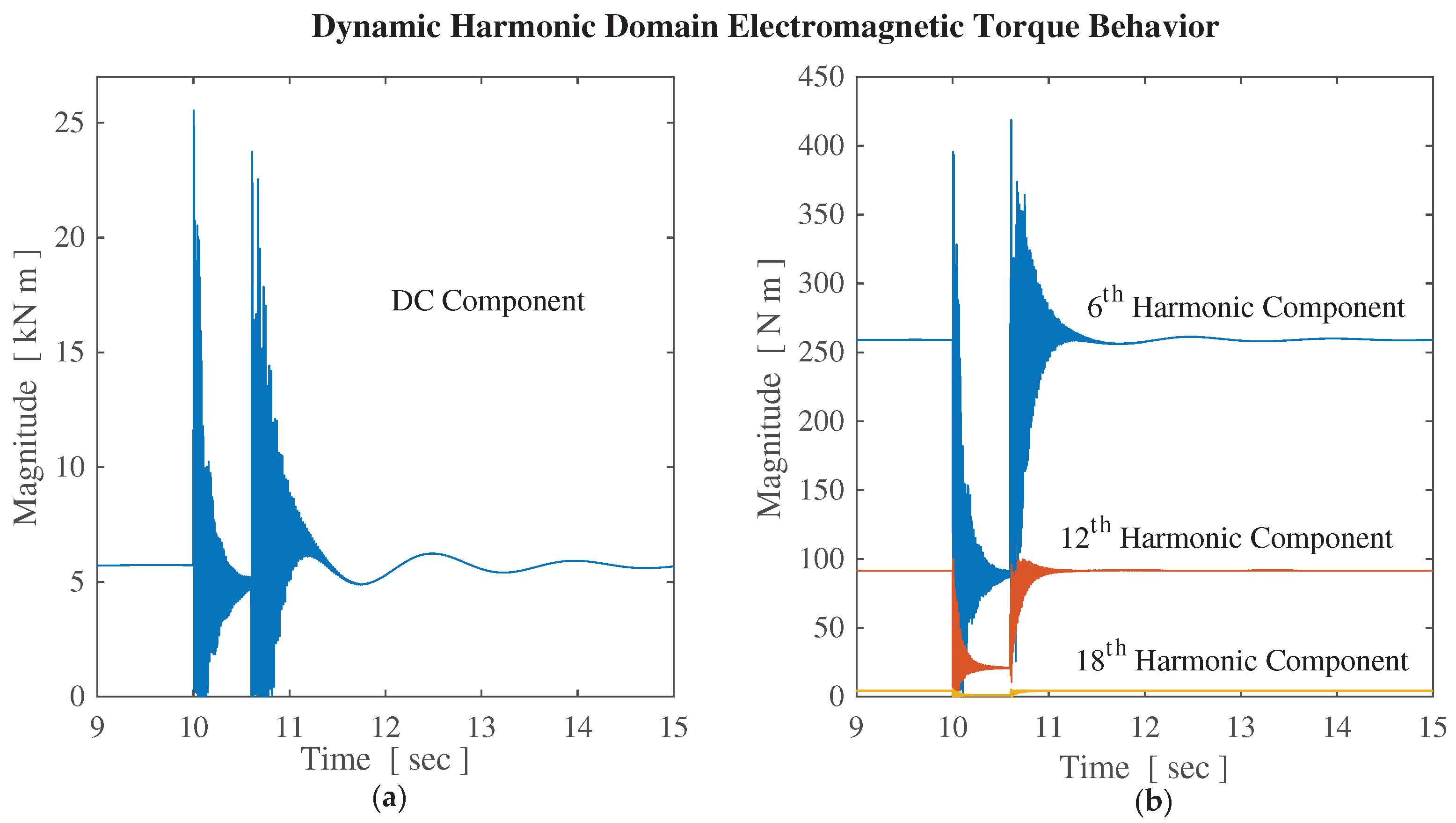
Therefore, to show the improvement introduced by the proposed models, Figure 5 presents the time evolution of the harmonics in the electromagnetic torque with harmonic distortion. Although there are only odd harmonic components in the electrical system, the harmonic cross-coupling generates even harmonic multiples of six at the mechanical variables. As previously mentioned, the time domain waveform of the electromagnetic torque (Figure 4) presents some oscillations caused by the harmonic distortion in the electric power system, and the proposed methodology allows us to learn exactly how these oscillations are composed. These harmonic distortion components are thus exposed, as shown in Figure 5, where the direct current component clearly dominates the dynamic behaviour of the electromagnetic torque, but the sixth harmonic and its multiples are the principal components of its oscillations. Learning this information is relevant since in wind turbines mechanical stress is the primary factor in terms of faults, damage, and maintenance, among others.
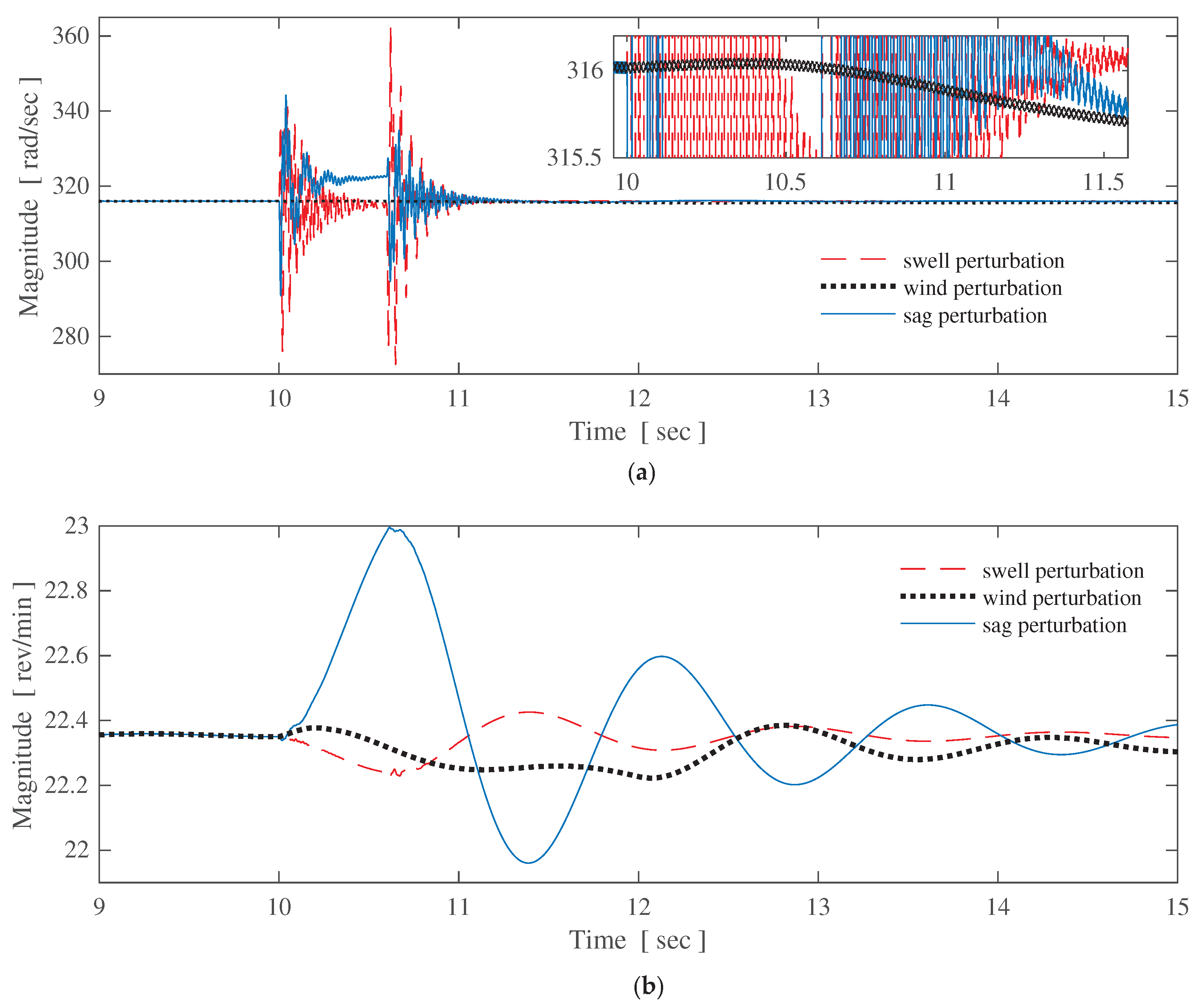
Similar effects are presented in the rest of the mechanical variables due to the harmonic distortion in the electric power system, but it should be noted that these effects are stronger in the induction generator, and decrease towards the wind turbine side, principally because of the action of the gearbox and the damping and stiffness of the drive train. This can be observed in Figure 6 and Figure 7, where the oscillations are much larger in the induction generator than in the wind turbine. It should be noted that the dynamic behaviour of the harmonic content was obtained for all the variables in the WTIG and in the power system.
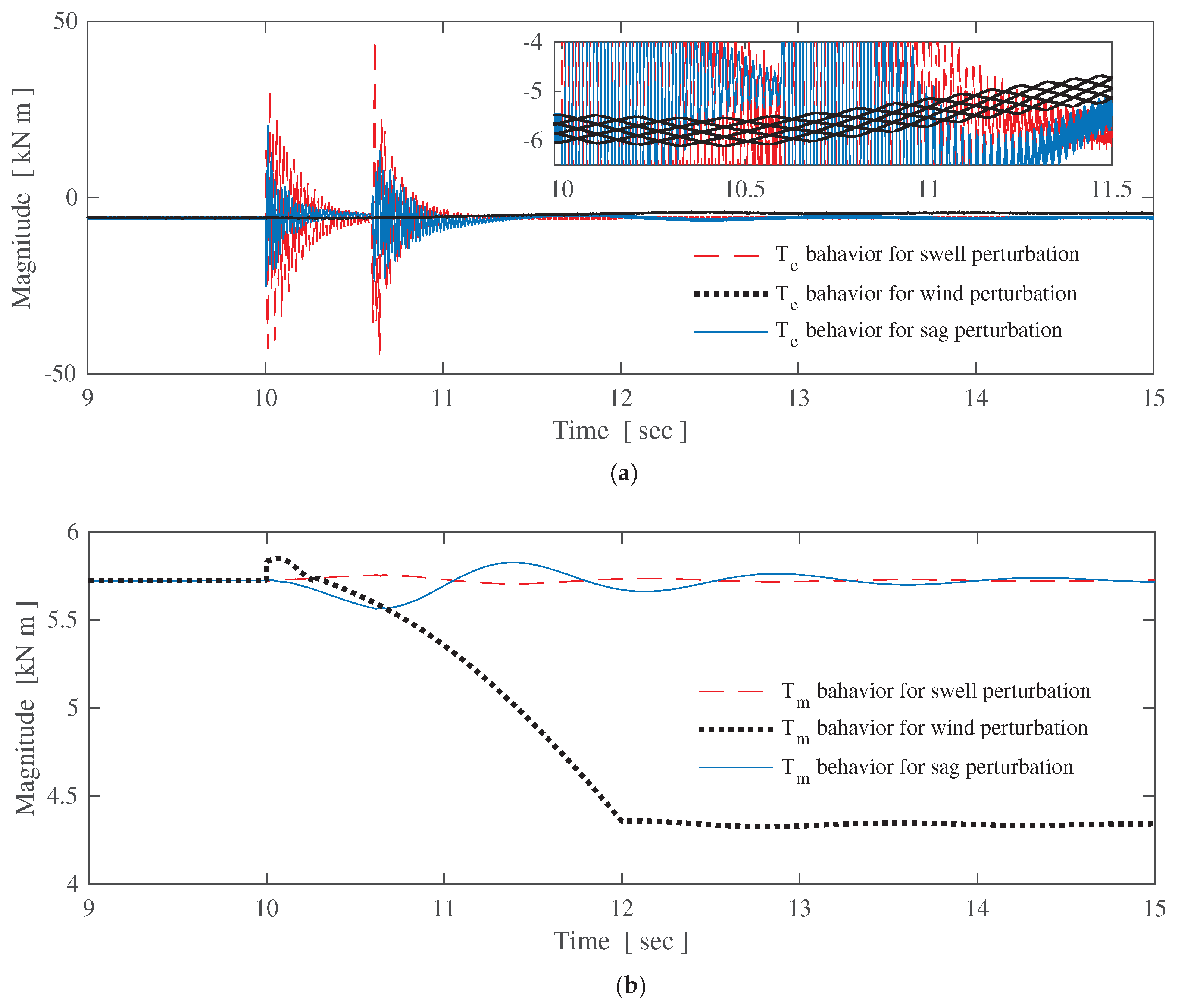
Here, a comparative analysis is presented with respect to the behaviour of the wind turbine generator in response to common power quality disturbances against the voltages sag and swell, as well as a change in the wind velocity from 15 m/s to 11 m/s. Figure 6 and Figure 7 show the time domain behaviour of selected mechanical variables of the wind power generator with the three previously mentioned disturbances starting at s. Notice in Figure 6 that the sag disturbance affects the wind turbine by increasing its speed, while the mechanical torque decreases, as shown in Figure 7. These figures also show that the voltage swell and the wind speed change have the opposite effect to the sag, but to a lesser extent. It is clear that the harmonic distortion has a larger impact in the rotor of the induction generator than in the wind turbine; this effect is shown in the form of oscillations or noise over the rotor speed curve (Figure 6). A similar conclusion is obtained for the electromagnetic torque (Figure 7a) in which not only is dynamic behaviour higher but it presents a higher distortion than the mechanical torque (Figure 7b). These waveforms were obtained considering all the harmonic components in current and voltage presented in the power network equivalent, i.e., the 5th, 7th, 11th, 13th, and 17th. Note that only positive and negative sequence harmonics are presented.
5.2. Electrical Response
A key fact in the harmonic analysis is the effect of the harmonics on the power losses and the reduction of the equipment life span. These effects are evident when the typical power relationships do not meet the power balance. Then, the power analysis must be undertaken remembering that in a system with waveform distortion the apparent power S is separated into three orthogonal components . P is the active power in watts (W), which is defined as,
Q is the reactive power in volt-ampere reactive (VAR), given by the multiplication of harmonic voltages and currents of the same frequency,
D is the distortion power in volt-ampere distortion (VAD), defined in terms of the harmonic components as the multiplication of harmonic voltages and currents of different frequencies; this component is a direct cause for the harmonic distortion,
A complete definition of the power components and other electrical relations under non-sinusoidal conditions is presented in [31].
The dynamic evolution of the apparent, active, reactive, and distortive powers in the induction machine terminals are presented in Figure 8. At first sight, it is clear that the active power is close to the extracted power from the wind, but the higher level of apparent power is generated because of the reactive power required for the operation of the induction machine, and additionally by the distortion power. In fact, the impact that the harmonic distortion has over the power requirements of the induction generator in the form of distortion power can be appreciated. While the active and reactive power values are close to those values obtained under sinusoidal conditions, the apparent power is higher. Consequently, the harmonic distortion increases the apparent power requirements, and then the losses, which affects the proper operation of the induction machine.
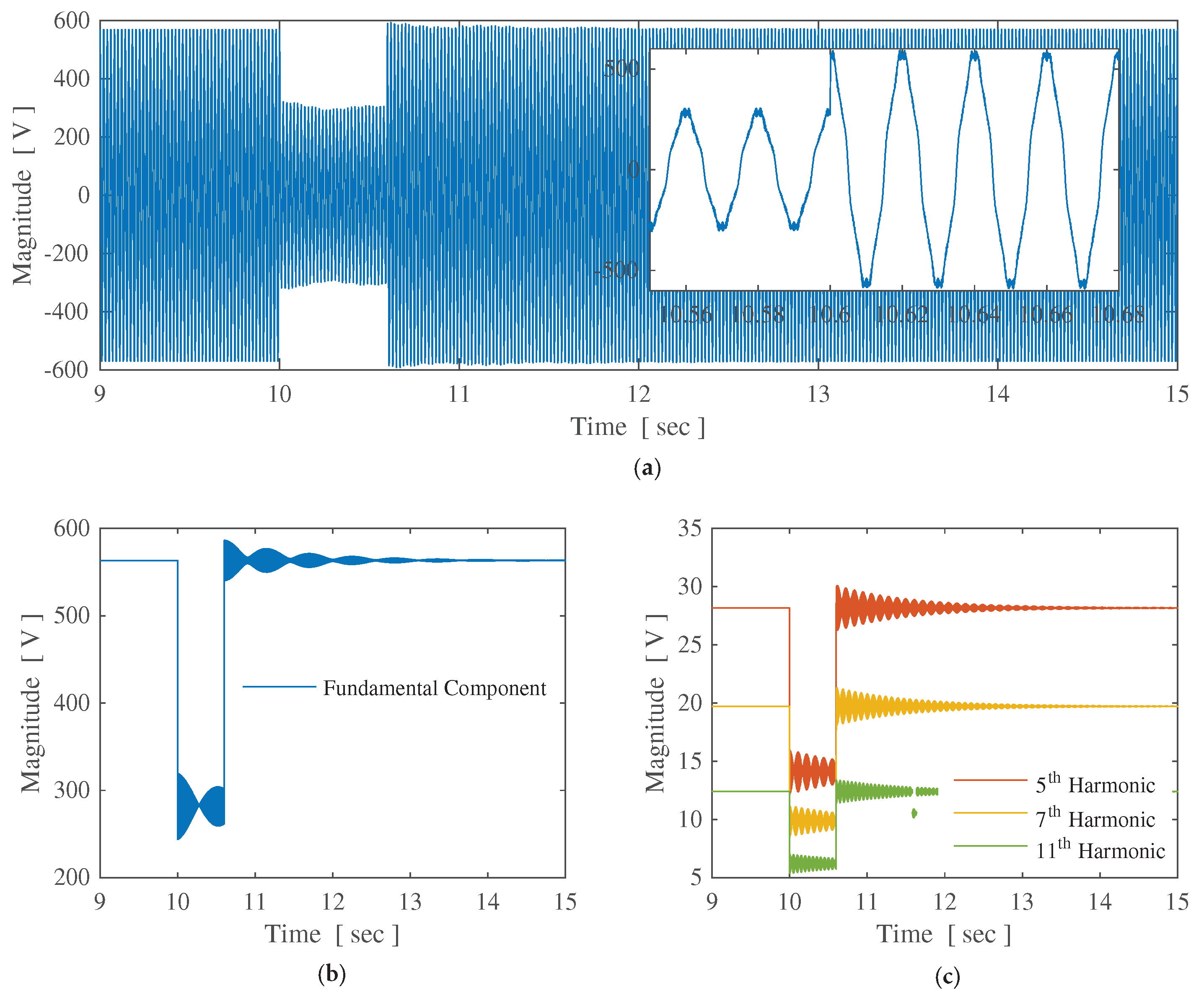
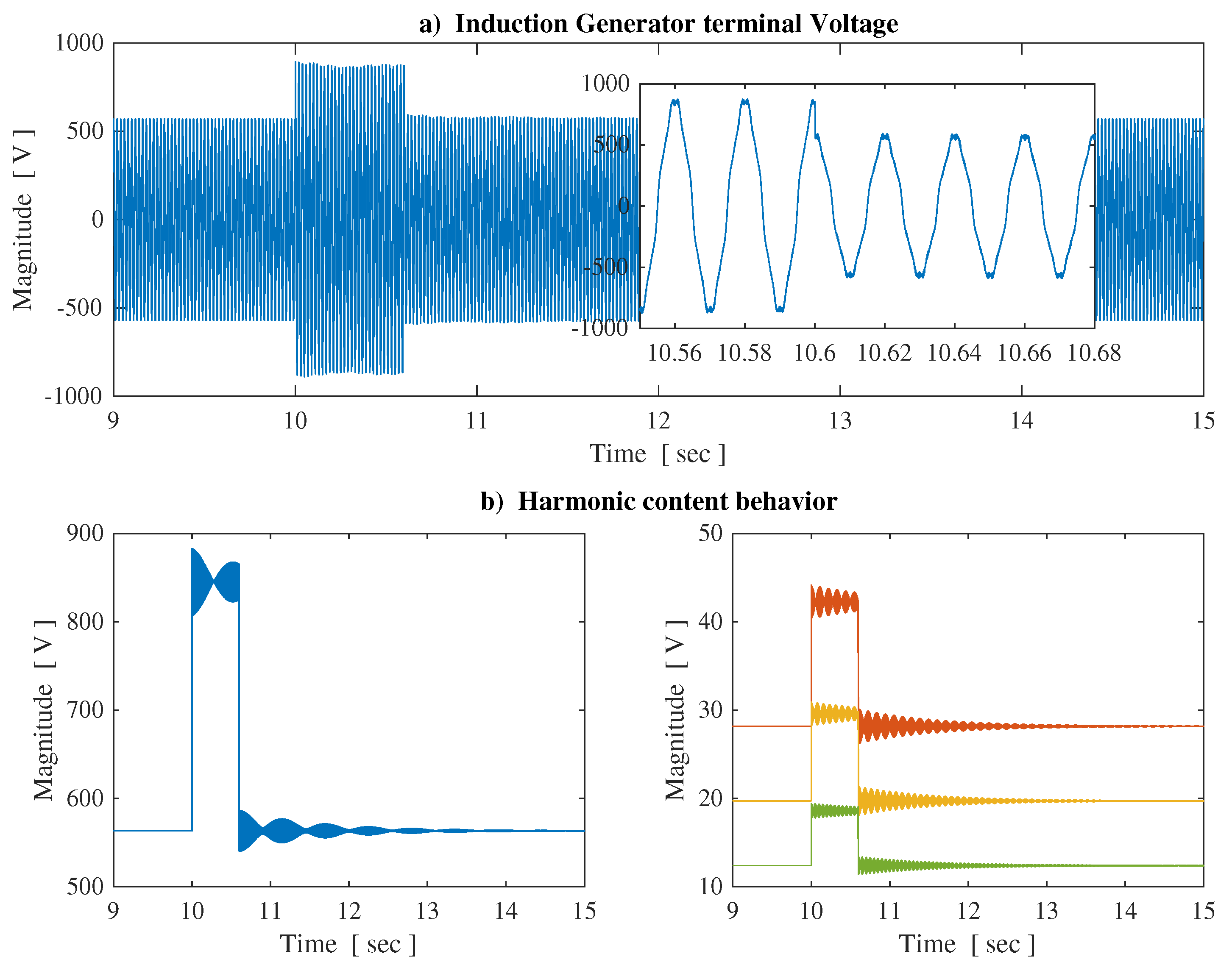
Remember that the principal characteristic of the dynamic harmonic domain methodology is its capacity to compute each harmonic individually, explicitly taking into account harmonic cross-coupling. The voltages at terminals of the induction generator are shown in Figure 9 and Figure 10. Note that behaviour is affected by the operation of the induction generator itself. The sag and swell in voltage perturbation can be observed in the time domain waveforms shown in Figure 9a and Figure 10a, respectively. However, Figure 9b and Figure 10b also present the harmonic content evolution of the same voltage; these figures show the dynamic behaviour of the principal harmonics presented in the voltage. At this point, it is important to remark that the time domain results, i.e., graphics in Figure 9a and Figure 10a, can be obtained from the dynamic harmonic domain results presented in Figure 9b and Figure 10b, respectively, but not vice versa. As expected, the dynamics in the harmonic content of the voltage at terminals of the induction generator are principally dependent on the capacitor bank; also, the behaviour of the harmonic content in the voltage and current is strongly tied to the behaviour of the electromagnetic torque, as can be appreciated in Figure 9 and Figure 10, and thus determines the behaviour of the power requirements, as shown in Figure 8.
Figure 11 shows the dynamic behaviour of the harmonic content in the current in the stator of the induction machine. Please note that the same information is available for any harmonic component of any mechanical or electrical variable of the test system. Then, the harmonic content information obtained with the proposed model is necessary to study the interaction between the induction generator, the power system, and the power electronic devices.
The harmonic studies provide the precise identification of the instants in which the dynamics start and end. Besides, the power quality indices can be computed in an easy and straightforward way with the harmonic components explicitly available, e.g., the total harmonic distortion (THD), and the RMS values, among others.
Notice that the time evolution of the harmonic components and the power quality indices (as shown in previous figures), can be easily computed in the DHD since the harmonic components are already available, whereas the time domain approaches require additional processes in order to obtain the harmonic information from the time domain waveforms. For steady-state time domain waveforms, the Fourier integral or the fast Fourier transform are widely used; however, for transient state in the time domain, high-precision methods for the computation of the harmonic components are not readily available.
6. Conclusions
For wind power studies, an efficient model based on the dynamic harmonic domain has been proposed for the induction generator. The model provides complete information on the harmonic content evolution throughout the whole system. This model has been proven in a typical test system using harmonic distortion and typical power quality perturbations. It has been shown that the proposed model can compute the transient and steady-state solution of practical power networks with wind power generation systems, power electronic converters, and non-linear components. These are harmonic sources and consequently are a perfect match with the proposed modelling approach in order to perform harmonic analysis of large and complex systems. Another remarkable characteristic of the presented approach is its capability to study and analyse the effects of harmonic distortion on the behaviour of the wind turbine drive train. As presented in the paper, it is possible to compute exactly which harmonic impacts directly on the mechanical dynamics of the drive train. The fact that the proposed approach computes every harmonic individually enables the possibility of analysing the harmonic interaction between the induction generator and the power electronic devices used for the interconnection to the power grid.
The obtained results show interesting information. It has been shown that the negative and positive sequence harmonic multiples of six caused by a six-pulse VSC produce the odd zero sequence harmonic in the mechanical subsystem, i.e., 6th, 12th, 18th, etc. It has also been shown that the dynamic behaviour of the system is mainly dominated by the behaviour of the electromagnetic torque. Regarding the presented power analysis, the importance of the harmonic distortion with respect to the power production of the generator, represented in the form of distortion power, is also clear. Considering harmonic distortion only, the distortion power represents more than 10% of the active power, but has major effects when other disturbances appear. For example, when the extracted power is lower than the nominal power, the importance of the distortion power increases since a constant value is maintained while the active power decreases, reaching 15% for the presented case. A larger effect is produced for the swell disturbance presented, reaching more than 20% with respect to the active power.
Finally, please note that the proposed model has been only tested on a small network, solely in order to probe its performance; however, this model can be used for larger and more complex systems. In addition, note that the SCIG has been tested, but the model can be applied to the DFIG if the CHCM of the power electronics converters is included.
Acknowledgments
Juan Segundo would like to thank the project FORDECYT 190966 for use of their facilities to carry out this research.
Author Contributions
H. García and J. Segundo conceived and developed the presented model; O. Rodrígez and R. Campos contributed with the framework on wind-based generation systems and made the mechanical analysis; H. García performed the simulations; and O. Jaramillo contributed with the adjustment and analysis of the test system. All the authors contributes to the writing and edition of the paper.
Conflicts of Interest
The authors declare no conflict of interest.
Abbreviations
The following abbreviations are used in this manuscript:
| WTIG | Wind Turbine Induction Generator |
| SCIG | Squirrel Cage Induction Generator |
| WRIG | Wound Rotor Induction Generator |
| DFIG | Doubly-Fed Induction Generator |
| CHCM | Companion Harmonic Circuit Model |
| DHD | Dynamic Harmonic Domain |
| THD | Total Harmonic Distortion |
| STATCOM | Static Compensator |
| VSC | Voltage Source Converter |
Appendix A
In the previous inductance expressions, and are the leakage and magnetizing inductances, respectively. On the other hand, the inductance is the amplitude of the mutual inductances between stator and rotor windings.
In the induction machine Equation (8), the matrix is given by
and is the machine angular speed.
According to the dynamic harmonic domain methodology, Equation (8) is expressed for dynamic harmonic analysis as
Finally, the matrices in the companion harmonic circuit model in Equation (9) are defined by
is the integration step, and is the operational matrix of differentiation. Note that the time-varying nature of the complex matrix is due to the rotor angular position, since
that could be expressed in the DHD as
and, finally, the CHCM for the rotor angular position is given by
where
Appendix B
The state-space equations that model the dynamic behaviour of the two-mass shaft in the dynamic harmonic domain using matrix notation are
References
- Julieta, S.-R. A methodological review to estimate techno-economical wind energy production. Renew. Sustain. Energy Rev. 2013, 21, 272–287. [Google Scholar]
- Gupta, N. A review on the inclusion of wind generation in power system studies. Renew. Sustain. Energy Rev. 2016, 59, 530–543. [Google Scholar] [CrossRef]
- Carlin, P.W.; Laxson, A.S.; Muljadi, E.B. The history and state of the art of variable-speed wind turbine technology. Wind Energy 2003, 6, 129–159. [Google Scholar] [CrossRef]
- Nemmour, A.L.; Mehazzem, F.; Khezzar, A.; Hacil, M.; Louze, L.; Abdessemed, R. Advanced Backstepping controller for induction generator using multi-scalar machine model for wind power purposes. Renew. Energy 2010, 35, 2375–2380. [Google Scholar] [CrossRef]
- Poitiers, F.; Bouaouiche, T.; Machmoum, M. Advanced control of a doubly-fed induction generator for wind energy conversion. Electr. Power Syst. Res. 2009, 79, 1085–1096. [Google Scholar] [CrossRef]
- Zou, Y.; Elbuluk, M.E.; Sozer, Y. Simulation comparisons and implementation of induction generator wind power systems. IEEE Trans. Ind. Appl. 2013, 49, 1119–1128. [Google Scholar] [CrossRef]
- Saini, M.K.; Kapoor, R. Classification of power quality events—A review. Int. J. Electr. Power Energy Syst. 2012, 43, 11–19. [Google Scholar] [CrossRef]
- Medina, A.; Segundo-Ramirez, J.; Ribeiro, P.; Xu, W.; Lian, K.L.; Chang, G.W.; Dinavahi, V.; Watson, N.R. Harmonic analysis in frequency and time domain. IEEE Trans. Power Deliv. 2013, 28, 1813–1821. [Google Scholar] [CrossRef]
- Song, Y.; Wang, X.; Blaabjerg, F. High-frequency resonance damping of DFIG-based wind power system under weak network. IEEE Trans. Power Electron. 2017, 3, 1927–1940. [Google Scholar] [CrossRef]
- Song, Y.; Blaabjerg, F. Overview of DFIG-based wind power system resonances under weak networks. IEEE Trans. Power Electron. 2017, 6, 4370–4394. [Google Scholar] [CrossRef]
- Liu, Z.; Rong, J.; Zhao, G.; Luo, Y. Harmonic assessment for wind parks based on sensitivity analysis. IEEE Trans. Sustain. Energy 2017, 4, 1373–1382. [Google Scholar] [CrossRef]
- Ebrahimzadeh, E.; Blaabjerg, F.; Wang, X.; Bak, C.L. Harmonic stability and resonance analysis in large PMSG-based wind power plants. IEEE Trans. Sustain. Energy 2018, 9, 12–23. [Google Scholar] [CrossRef]
- Djurović, S.; Vilchis-Rodriguez, D.S.; Smith, A.C. Supply induced interharmonic effects in wound rotor and doubly-fed induction generators. IEEE Trans. Energy Convers. 2015, 30, 1397–1408. [Google Scholar] [CrossRef]
- Burton, T.; Sharpe, D.; Jenkins, N.; Bossanyi, E. Wind Energy Handbook; John Wiley and Sons, Ltd.: Hoboken, NJ, USA, 2011. [Google Scholar]
- Pathak, A.K.; Sharma, M.P.; Mahesh, B. A critical review of voltage and reactive power management of wind farms. Renew. Sustain. Energy Rev. 2015, 51, 460–471. [Google Scholar] [CrossRef]
- Mahela, O.P.; Shaik, A.G. Comprehensive overview of grid interfaced wind energy generation systems. Renew. Sustain. Energy Rev. 2016, 57, 260–281. [Google Scholar] [CrossRef]
- Jawad, F.; Seyed, M.M.; Mohsen, B.; Sérgio, M.A. Magnetic equivalent circuit modelling of doubly-fed induction generator with assessment of rotor inter-turn short-circuit fault indices. IET Renew. Power Gener. 2016, 10, 1431–1440. [Google Scholar]
- Djurović, S.; Williamson, S.; Renfrew, A. Dynamic model for doubly-fed induction generators with unbalanced excitation, both with and without winding faults. IET Electr. Power Appl. 2009, 3, 171–177. [Google Scholar] [CrossRef]
- Hernandez, E.; Madrigal, M. A step forward in the modeling of the doubly-fed induction machine for harmonic analysis. IEEE Trans. Energy Convers. 2014, 29, 149–157. [Google Scholar] [CrossRef]
- Rico, J.J.; Madrigal, M.; Acha, E. Dynamic harmonic evolution using the extended harmonic domain. IEEE Trans. Power Deliv. 2003, 18, 587–594. [Google Scholar] [CrossRef]
- Garcia, H.; Madrigal, M. Companion harmonic circuit models for transient studies. Electr. Eng. 2013, 95, 43–51. [Google Scholar] [CrossRef]
- Dommel, H.W.; Bhattacharya, S.; Brandwajn, V.; Lauw, H.K. Electromagnetic Transients Program Reference Manual: EMTP Theory Book; Bonneville Power Administration: Portland, OR, USA, 1986. [Google Scholar]
- Krause, P.C.; Wasynczuk, O.; Sudhoff, S.D.; Pekarek, S. Analysis of Electric Machinery and Drive Systems; John Wiley and Sons: Hoboken, NJ, USA, 2013. [Google Scholar]
- Wang, Q.; Chang, L. An intelligent maximum power extraction algorithm for inverter-based variable speed wind turbine systems. IEEE Trans. Power Electron. 2004, 19, 1242–1249. [Google Scholar] [CrossRef]
- Wai, R.J.; Lin, C.Y.; Chang, Y.R. Novel maximum-power-extraction algorithm for PMSG wind generation system. IET Electr. Power Appl. 2007, 1, 275–283. [Google Scholar] [CrossRef]
- Thomas, A. Wind power in power systems. Wind Eng. 2006, 30, 447–449. [Google Scholar]
- Bollen, M.H.J. Solving Power Quality Problems: Voltage Sags and Interruptions; IEEE Press: New York, NY, USA, 1999. [Google Scholar]
- Remus, T.; Marco, L.; Pedro, R. Grid Converters for Photovoltaic and Wind Power Systems; Wiley-IEEE Press: Indianapolis, IN, USA, 2011. [Google Scholar]
- Farhad, S.; Sumedha, R.; Arindam, G. Static Compensators (STATCOMs) in Power Systems; Springer: Singapore, 2014. [Google Scholar]
- Zbigniew, L. Wind Turbine Operation in Electric Power Systems, Series: Advanced Modeling; Springer: Berlin/Heidelberg, Germany; CBS Publishers: New Delhi, India, 2003. [Google Scholar]
- Enrique, A.; Manuel, M. Power Systems Harmonics, Computer Modelling and Analysis; John Wiley and Sons Incorporated: New York, NY, USA, 2001. [Google Scholar]
Figure 1.
Companion harmonic circuit model for the induction machine.

Figure 2.
Two-mass shaft model of the wind turbine.

Figure 3.
Typical test system for interconnection.

Figure 4.
Electromagnetic torque in the induction generator.

Figure 5.
Harmonic content of the electromagnetic torque in the induction generator: (a) Direct current component; (b) Even harmonics.
Figure 5.
Harmonic content of the electromagnetic torque in the induction generator: (a) Direct current component; (b) Even harmonics.

Figure 6.
Dynamic response in the wind turbine torque: (a) Electromagnetic Torque; (b) Mechanical Torque.
Figure 6.
Dynamic response in the wind turbine torque: (a) Electromagnetic Torque; (b) Mechanical Torque.

Figure 7.
Dynamic response in the angular speed on both sides of the drive train: (a) Induction Generator Rotor Speed; (b) Wind Turbine Speed.
Figure 7.
Dynamic response in the angular speed on both sides of the drive train: (a) Induction Generator Rotor Speed; (b) Wind Turbine Speed.

Figure 8.
Dynamics in the power components required for the wind turbine induction generator (WTIG). (a) Apparent Power; (b) Active Power; (c) Reactive Power; (d) Distortion Power.
Figure 8.
Dynamics in the power components required for the wind turbine induction generator (WTIG). (a) Apparent Power; (b) Active Power; (c) Reactive Power; (d) Distortion Power.

Figure 9.
Voltage sag in the induction generator; (a) Time domain waveform; (b) Fundamental component; and (c) Harmonic content.
Figure 9.
Voltage sag in the induction generator; (a) Time domain waveform; (b) Fundamental component; and (c) Harmonic content.

Figure 10.
Voltage swell in the induction generator; (a) Time domain waveform; (b) Fundamental component; and (c) Harmonic content.
Figure 10.
Voltage swell in the induction generator; (a) Time domain waveform; (b) Fundamental component; and (c) Harmonic content.

Figure 11.
Dynamic behaviour of the harmonic current in the induction generator; (a) Time domain waveform; (b) Fundamental component; and (c) Harmonic content.
Figure 11.
Dynamic behaviour of the harmonic current in the induction generator; (a) Time domain waveform; (b) Fundamental component; and (c) Harmonic content.


Table 1.
Wind turbine induction generator data.
| Element | Value |
|---|---|
| Wind Turbine Data | |
| Rated power, | 900 kW |
| Rotor diameter, | m |
| Gearbox ratio | |
| Drive Train Data | |
| Turbine inertia, | kg· m2 |
| Generator inertia, | kg·m2 |
| Stiffness of the shaft, | N·m/rad |
| Damping coefficient, | N·m·s/rad |
| Generator Data | |
| Nominal voltage, | 690 V, 50 Hz |
| Pole-pairs | 2 |
| Stator resistance, | |
| Rotor resistance, | |
| Stator leakage reactance, | |
| Rotor leakage reactance, | |
| Magnetizing reactance, | |
© 2018 by the authors. Licensee MDPI, Basel, Switzerland. This article is an open access article distributed under the terms and conditions of the Creative Commons Attribution (CC BY) license (http://creativecommons.org/licenses/by/4.0/).
Share and Cite
MDPI and ACS Style
García, H.; Segundo, J.; Rodríguez-Hernández, O.; Campos-Amezcua, R.; Jaramillo, O. Harmonic Modelling of the Wind Turbine Induction Generator for Dynamic Analysis of Power Quality. Energies 2018, 11, 104. https://doi.org/10.3390/en11010104
AMA Style
García H, Segundo J, Rodríguez-Hernández O, Campos-Amezcua R, Jaramillo O. Harmonic Modelling of the Wind Turbine Induction Generator for Dynamic Analysis of Power Quality. Energies. 2018; 11(1):104. https://doi.org/10.3390/en11010104
Chicago/Turabian StyleGarcía, Héctor, Juan Segundo, Osvaldo Rodríguez-Hernández, Rafael Campos-Amezcua, and Oscar Jaramillo. 2018. "Harmonic Modelling of the Wind Turbine Induction Generator for Dynamic Analysis of Power Quality" Energies 11, no. 1: 104. https://doi.org/10.3390/en11010104
Note that from the first issue of 2016, this journal uses article numbers instead of page numbers. See further details here.