Investigation of a Novel Coaxial Power-Split Hybrid Powertrain for Mining Trucks


1
School of Mechanical Engineering, University of Science and Technology Beijing, Beijing 100083, China
2
Faculty of Engineering and IT, University of Technology Sydney, 15 Broadway, Ultimo NSW 2007, Australia
*
Author to whom correspondence should be addressed.
Energies 2018, 11(1), 172; https://doi.org/10.3390/en11010172
Submission received: 16 November 2017
/
Revised: 8 January 2018
/
Accepted: 9 January 2018
/
Published: 11 January 2018
Abstract
:Due to the different working conditions and specification requirements of mining trucks when compared to commercial passenger vehicles, better fuel efficiency of mining trucks could lead to more significant economic benefits. Therefore, investigating a hybrid transmission system becomes essential. A coaxial power-split hybrid powertrain system for mining trucks is presented in this paper. The system is characterized as comprising an engine, a generator (MG1), a motor (MC2), two sets of planetary gears, and a clutch (CL1). There are six primary operation modes for the hybrid system including the electric motor mode, the engine mode, the hybrid electric mode, the hybrid and assist mode, the regenerative mode, and the stationary charging mode. The mathematical model of the coaxial power-split hybrid system is established according to the requirements of vehicle dynamic performance and fuel economy performance in a given driving cycle. A hybrid vehicle model based on a rule-based control strategy is established to evaluate the fuel economy. Compared with the Toyota Hybrid System (THS) and the conventional mechanical vehicle system using a diesel engine, the simulation results based on an enterprise project indicate that the proposed hybrid system can enhance the vehicle’s fuel economy by 8.21% and 22.45%, respectively, during the given mining driving cycle. The simulation results can be used as a reference to study the feasibility of the proposed coaxial hybrid system whose full potential needs to be further investigated by adopting non-causal control strategies.
1. Introduction
Mining trucks are widely used as the primary transportation for mining and water conservancy projects. The operations of the mining trucks have the following characteristics: the daily operational time is usually over 20 h and the trucks travel to and fro between the loading point and the unloading point with a relatively fixed route. The road slope and truckload change greatly, and the trucks frequently drive uphill and downhill. These will cause serious emissions, harsh noises, and poor economic performances [1]. Therefore, it is essential to reduce the fuel consumption and emissions of mining trucks by making a more efficient drive-train system [2].
Currently, the primary transmission systems for mining trucks can be classified into two types: (1) a conventional internal combustion engine based on a mechanical transmission system including the corresponding hydraulic automatic transmission, and (2) the electric driving system consisting of the engine, generator, and motor. A hydraulic mechanical mining truck requires a torque converter to increase output torque in a low-speed climbing stage, which results in low transport efficiency [3]. The emergence of the electric driving systems helps solve the difficulty of manufacturing a sizeable hydraulic torque converter and other transmission components [4]. The difference between the electrical driving system and the hydraulic mechanical system is that the engine speed no longer has a direct correspondence with the vehicle speed in the electric driving mode. The electrical driving system provides more possibilities for optimizing control of the vehicle, providing higher fuel economy using the engine, and even offsetting the drawback of the efficiency in the electric driving system being usually less than the transmission efficiency of the mechanical drive system due to energy conversion. With the development of electrical driving technology for passenger vehicles, the pure electrical transmission system and the hybrid electrical transmission system have been also applied in off-road vehicles in recent years [5]. The types of off-road vehicle transmission systems tend to be diversified, which further provides the possibility to reduce fuel consumption of the mining trucks.
Currently, hybrid technology is considered one of the most effective ways to improve overall efficiency and reduce emissions [6]. Compared with the conventional mechanical vehicle system and the electric driving system, fuel consumption and pollutant emissions can be effectively reduced at low engine speed and low engine torque. Moreover, braking energy loss during deceleration can also be reduced due to two power sources being used in the hybrid system. The two power sources consist of an engine and an energy storage system (usually a battery) [7,8]. The hybrid system typically consists of a series hybrid system, a parallel hybrid system, and a power-split hybrid system [9]. The series hybrid system can enhance fuel efficiency under low-speed cycles [10]. Nevertheless, the parallel hybrid system has higher efficiency under high-speed driving conditions compared to the series hybrid system and vice versa [11]. The power-split hybrid system possesses all the advantages in series and parallel hybrid systems. The motor can drive the vehicle directly at low-speed and recover braking energy to avoid energy loss when the vehicles drive downhill. Additionally, the engine can be completely decoupled from the vehicle speed to avoid the engine operating at low-speed and low-load conditions [12].
In recently developed HEVs, speed coupling configurations are widely used [13], as shown in Figure 1. The Toyota Hybrid System could enhance energy efficiency in low-speed driving conditions. It includes two sets of planetary gears with no clutches or brakes, as shown in Figure 1a where, R, C, S is the ring gear, planet carrier and sun gear respectively; CL is the clutch; BR is the brake. However, due to the engine and the generator always being coupled by a planetary gear and the engine driving the generator to output the power, waste takes place during energy conversion and energy efficiency of THS is low in high-speed driving conditions [14,15]. In contrast to the THS, the China hybrid system (CHS) includes two sets of planetary gears and a brake (BR1), as shown in Figure 1b, which has an advantage of the generator and motor driving the vehicle at the same time the brake is engaged [16]. The emergence of the CHS helps solve the problem that the engine cannot be locked even the system operates in an electric drive mode. However, none of them work in the parallel hybrid mode in high-speed driving conditions. Compared to the THS and CHS, Renault IVT system includes two sets of planetary gears and two brakes (BR1 and BR2) to achieve three modes, as shown in Figure 1c. When the vehicle drives in the low-speed mode, the brake (BR1) is engaged at the same time while the engine and the motor (MC2) are coupled. For a high-speed scenario, the brake (BR2) is engaged instead, and the engine can drive the vehicle directly without energy conversion. If SOC is low, the brakes (BR1 and BR2) are turned off [17]. The drawback of the Renault IVT system is that the motor cannot drive the vehicle in low-speed. GM-Allison AHS is known as a dual-mode hybrid system consisting of two sets of planetary gears, two clutches and a brake, as shown in Figure 1d, which can achieve these goals. However, the AHS system makes the control algorithm complicated and causes a high failure rate [18,19]. Moreover, compared to a parallel hybrid system designed by Volvo, the fuel economy of AHS is not significantly improved [20]. The Sport hybrid I-MMD system and the coaxial power-split hybrid system proposed by Minggao both include a clutch to simplify the system structure as shown in Figure 1e,f, respectively. However, the Sport hybrid I-MMD system is not usually applied to mining trucks because of the un-coaxial structure [21,22]. When the truck equipped with the coaxial power-split hybrid system is in low-speed, the vehicle can only be driven by the motor, which requires large motor torque and power. This leads to large motor size and high manufacturing cost [23].
Since mining trucks often work at low speed and long downhill conditions, in this paper, a novel coaxial power-split hybrid system for mining trucks is proposed to enhance the fuel economy. In the proposed structure, only one clutch is used, so the engine can drive the truck directly in high-speed conditions and the reliability of the system can be improved. The engine, generator, and motor are arranged on the same side to reduce the axial size. Finally, for the sake of low-cost, a low-torque permanent magnet synchronous motor (PMSM) is specially designed.
Energy management strategies of the hybrid powertrain system are generally classified into two categories: rule-based control strategies and optimization-based control strategies [24,25]. Rule-based control strategies have the advantage of being implemented instantly. However, this depends on the intuition of engineers and if its adaptability is poor, the optimal solution of the system cannot be obtained [26]. The optimization-based control strategies can obtain the optimal global solution on the premise of known driving cycle conditions. However, it is not feasible for most hybrid vehicles, and it is usually used in combination with other algorithms or as a benchmark of local optimization algorithms [27]. Choosing different covariate variables and equivalent factors will directly affect optimization results in PMP and ECMS, respectively [28,29]. Therefore, although the rule-based control strategy cannot obtain the optimal solution, it is widely used and some scholars think it is also relatively accurate for evaluating system performances [23,24,25,26,27,28,29,30,31].
In this paper, the simulation models for the coaxial power-split hybrid system are constructed. Section 2 explains the configuration, design, and operating principles of the proposed hybrid system. The mathematical model for the hybrid system is established in Section 3. Section 4 describes the control strategies of the hybrid system including the operating modes definition and modes selection. Finally, simulation results and discussions on fuel consumption compared to THS and the conventional mechanical vehicle system are given to evaluate the proposed hybrid system.
2. System Description
The structure of the proposed coaxial power-split hybrid system for a mining truck where the planetary drive is adopted is shown in Figure 2. The crankshaft of the engine is directly connected to the planet carrier of the second planetary gear. The output shaft of the generator (MG1) is connected to the sun gear of the second planetary gear and then associated with the crankshaft of the engine via a clutch (CL1). The output shaft of the motor (MC2) is connected to the sun gear of the first planetary gear. The ring gear of the first planetary is fixed. The planet carrier of the first planetary gear is connected with the ring gear of the second planetary gear and then they are together attached to the final drive. The gross output power consists of some output power of the engine via the ring gear of the second planetary gear and the output power of MC2 via the planet carrier of the first planetary gear. The engine, MG1, MC2, and planetary gears are coaxial. Since MG1 and MC2 are both high-speed and arranged on the same side, the proposed hybrid system can be very compact, which can enhance mechanical efficiency. The parameters of various components for the proposed hybrid system are shown in Table 1.
The operation modes of the proposed hybrid system are explained below. When the vehicle is running at low or medium speed and the demand power is smaller than the battery power, the truck can be driven by MC2 if SOC is in the predetermined range. When SOC is low, the engine starts to drive MG1 to supply power to the battery or MC2. By this time, the gross output power consists of some output power of the engine and the outputting power of MC2. In this case, the system is similar to the series hybrid. As the vehicle speed is gradually increased and higher than the set speed, the vehicle will be driven by MC2 if SOC and the demand torque are low. Otherwise, when the clutch (CL1) is engaged, the engine will drive the vehicle directly. According to the external load conditions and the state of SOC, MC2 can act as a motor or generator and the system will be similar to the parallel hybrid at this time. Since the engine and MG1 are always coupled through the second planetary gear, the engine can continuously operate in the optimum fuel economy areas without being affected by external conditions. Compared to the series hybrid system, the size of the engine, MG1, MC2 can be reduced because they can work together to provide the demanded power. In contrast to the parallel system, the engine can be decoupled from the vehicle speed to avoid the engine operating at low-speed and low-load conditions. Therefore, the proposed hybrid system can enhance the energy efficiency of the system.
3. Mathematical Model
3.1. Vehicle and Powertrain Model
Since the rear axle drives the hybrid truck, the tractive force of the rear axle can be analyzed according to the longitudinal dynamic performance of the vehicle. The fuel economy of the proposed hybrid system is the primary consideration in this paper. Therefore, the damping and compliance are ignored to simplify the analysis. The formulas are as follows [32]:
where, is the rolling resistance, is the aerodynamic resistance, is the grade resistance, is the acceleration force, are rolling resistance coefficient, truck curb mass, truckload mass, acceleration constant of gravity, road slope, aerodynamic resistance coefficient, front area, vehicle speed and rotation component coefficient, respectively. Therefore, the requirement of the tractive force can be calculated.
According to the designed parameters of the hybrid mining truck, the front axle load and the rear axle load can be obtained. The formulas are as follows:
where , respectively, are the distances between the front and rear axles and the gravity center, is the vehicle wheelbase, is the effective rolling radius, is the height of the gravity center.
If the slip rate of tires is not ignored, the slip rate can be defined as the function of the tractive force and the vertical load of the drive shaft. The formula is as follows:
where is the slip rate of the tires.
During the braking process, the angular speed of the tires can be calculated by the following formula.
where is the angular speed of the tires.
3.2. Power Source Model
The engine plays a vital role in HEV. However, since it is a time-varying nonlinear system, the experimental engine model is adopted. The engine model considers the requested torque from the control strategy block based on the engine torque and the engine speed . The formula is as follows:
where is the moment of inertia of the engine.
Subsequently, the instantaneous fuel consumption of the engine can be obtained from a two-dimensional map, which is taken from the test measurement.
Next, the final fuel consumption can be obtained by integrating the total fuel quantity and the driving distance. The equivalent fuel consumption is calculated by the density of the diesel in the engine.
where, is the duration time of the driving cycle.
The battery module is usually simplified to the first order as seen in the approximated internal resistance model, and the impact of temperature and battery life are ignored [33]. The rule is that the positive power represents discharging and the negative power represents charging.
According to the battery equivalent circuit, the battery SOC is calculated as:
where is the maximum electrical charge and is the current of the battery.
Considering the battery pack voltage calculation module, the battery voltage is calculated as:
where n is the number of the single cell, is the voltage of the single cell, and is the internal resistance of a single cell.
The relationship between electricity consumption and fuel consumption is calculated as [34]:
where is the electricity consumption (kWh), is the fuel density (), is the low calorific value of fuel combustion (J/g), is the efficiency of the engine, and is the equivalent fuel consumption (L).
3.3. Electric Motor Model
The motor in the hybrid system can drive the truck or recover the kinetic energy, so the power of the motor can be calculated by using the following formula:
where is the motor output torque, is the motor output speed, and are the efficiency of the motor and generator, respectively.
The efficiency of the generator or motor can be determined using a two-dimensional map whose data are obtained by the test measurement during the discharge or the charge.
3.4. Mechanical Model
The clutch is adopted as an essential component which determines the operating status of the vehicle in the proposed hybrid system. The mathematical model of the clutch is studied as a simple friction structure [35]. Assuming represents the working state of the clutch, where denotes the mode of the clutch is off, and indicates the mode of the clutch is engaged. The expression can be expressed as:
where, is the gear ratio of the first and second planetary gears, respectively, and are the torques of the engine, generator, motor and transmission output shaft, respectively.
The rotating speed transmitted by the clutch is expressed as:
where, are the speeds of the engine, generator, motor, and transmission output shaft, respectively.
4. Control Strategy
4.1. Rule-Based Strategy for the Proposed System
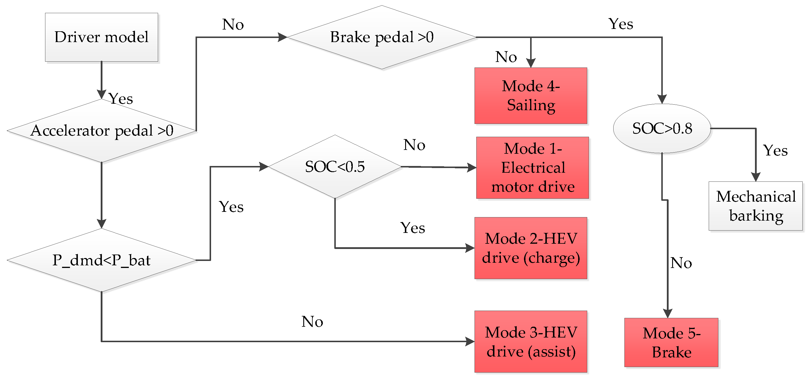
A rule-based control strategy for the proposed hybrid system is shown in Figure 3. As mentioned previously, the proposed hybrid system possesses the advantages of both the series system and the parallel hybrid system, which includes six modes. The operating modes are presented in Figure 4 and include: (a) electric motor drive, (b) hybrid electric drive (HEV) and the motor is generated or hybrid electric drive and assist (HEV + MC2), (c) engine drive, (E) engine drive and the motor is generated or engine drive and assist (E + MC2), and (d) regenerative. The control unit analyzes the signals of the pedal and the vehicle speed to make the system work in each operating mode. The operating modes are shown in Table 2.
When the driving pedal and the brake pedal is in a neutral state, the system operates in mode 6. If the brake pedal is greater than 0, then mode 7 is activated. When the vehicle speed is lower than 26 km/h, the SOC is higher than 0.4 and the demand power is less than the battery power. MC2 will drive the vehicle and the battery will supply the electric power while the system will operate in mode 1 where the maximum available output power is the rated power of MC2. Therefore, when the SOC is lower than 0.4 or the demanded power is greater than the power that MC2 or battery can supply, the system must switch to the hybrid-electric drive (HEV) or the hybrid electric drive (assist)/(HEV + MC2).
If the SOC is lower than 0.4 and the demand power is less than the optimal engine power, then mode 2 is activated. At this time, the engine starts and operates in the high efficiency area. Meanwhile, some engine power drives the generator to charge the battery or drive MC2, and the rest is used to drive the vehicle.
When the demanded power is greater than the optimal engine power, mode 8 must be activated. At this time, the maximum output power of the system is 0.7 times of the engine power and the motor rated power, which can obviously enhance the drivability of the mining trucks.
The rule-based control strategies for the engine drive mode are similar to the parallel hybrid system. When the vehicle speed is greater than 26 km/h, the truck will be driven by MC2 and the system will operate in mode 1 if SOC is higher than 0.7 and the demand power or torque is low. Otherwise, the clutch is engaged and the engine drives the mining truck directly. If the requirement of power is smaller than the minimum engine power and SOC is low, MC2 can be used as a generator to make the engine work in high-efficiency. In this case, mode 3 is turned on. Mode 4 will be selected when the demand power is between the minimum engine power and the optimal power. Otherwise, MC2 can be boosted to supply the power. The system will work in mode 5 at this time. According to the different operation modes, the engine speed and torque are optimized, and so the engine operating points can be maintained in the high-efficiency area.
4.2. Rule-Based Strategy for THS
Compared to the proposed hybrid system in this paper, THS cannot make the engine drive the vehicle directly. Therefore, the system only works in an electric motor mode, an HEV (charge) mode, and an HEV (assist) mode. The rule-based strategy is presented in Figure 5.
4.3. Dynamic Gear Shifting Strategy for the Conventional Mechanical System
A gear shifting strategy directly affects the power performance and fuel economy of the vehicle. The optimizing shift strategy for dynamic performance can make the system output maximize the tractive force and the maximum power of the engine. In this paper, since the working conditions of mining trucks are poor, the shift strategy for dynamic performance is designed for the conventional mechanical vehicle. The throttle opening and vehicle speed are considered as the control parameters while the tractive force is calculated by the engine output power. Then, the corresponding tractive force curve is drawn in each gear, and the shift speed is obtained by using the intersection speed of the tractive forces of the different gears. The downshifting point is calculated by choosing the appropriate convergence rate based on the dynamic gear upshifting strategy. Then, the downshifting strategy is obtained. Two-parameter dynamic gear shifting strategy is shown in Figure 6.
5. Simulation Results and Discussions
The simulation model is built using Matlab/Simulink R2014a based on the mathematical model of the coaxial power-split hybrid system. The simulation model can be used to evaluate the driving performance and the fuel economy of the proposed hybrid system by combining the backward-facing and forward-facing methods. In the paper, the built simulation model is based on a mechanical mining truck named TR30 as the prototype, which is manufactured by Inner Mongolia North Hauler Joint Stock Co. Ltd. (Inner Mongolia, China). The corresponding parameters of the mining truck are listed in Table 3.
5.1. Fuel Economy for Hybrid Powertrain System
The performance characteristics of the designed coaxial power-split hybrid system are analyzed by using the typical mining driving cycle according to the operation datum given by the reference [36]. The cycle time is 2098 s, mileage is 11.66 km, the max speed is 60 km/h, the average speed is 20.5 km/h, and the max slope is ±10%. Driving uphill with full-load lasts 940 s, and then the simulated unloading time is set to 25 s. The other model is driving the downhill with no-load, as shown in Figure 7. The cycle consists of the following characteristics: waiting to be loaded, driving uphill on a flat road with a full load, unloading in the flat road, and driving downhill on a flat road with no-load.
The actual vehicle speed (carmine dotted line) follows the target vehicle speed (solid black line) adequately, as shown in Figure 7a. The presence of the motor significantly improves the acceleration performance of the proposed hybrid system. The maximum engine speed and the motor speed will limit the maximum vehicle speed. Therefore, the ratios of planetary gears are selected to achieve maximum speed and, simultaneously, make the motor and engine work in the high-efficiency region.
The power demanded during the driving cycle is shown in Figure 8c and the maximum demand power is 232 kW, which is around 460 s and shown as the carmine dotted line. If it is a conventional mechanical system, the selected engine power must meet the maximum demand power. In other words, it is higher than 232 kW for the mining truck. However, due to the presence of the battery, the engine power can be less than 232 kW, and even decline to 200 kW. For instance, when the system works in mode 8, the engine and MC2 provide the power together and the maximum output power is higher than 280 kW for the proposed system, which meets the performance requirement. During the braking process, the MC2 can be a generator to recover the braking energy and charge the battery. The analyzed demand power of the engine is shown as the black solid line. The operating time of the engine is not full. The demand power of the engine varies between 0 kW and 218 kW during the entire driving cycle because the motor can be assisted and the other energy is provided by the battery. The battery energy comes from two processes: the regenerative energy braking process and the generator process.
Figure 8a,b show the calculated speed and torque of the engine, respectively. The engine speed is around 1100 r/min when the system is in the HEV mode. This can improve the engine efficiency. During high-speed conditions, the engine speed varies because of the vehicle speed, and the request torque is provided by the engine and motor to enhance the efficiency. If the system operates in the electric motor mode, the engine will stop.
The operation modes of the proposed hybrid system in the given cycle are shown in Figure 9. The load, SOC value, and the vehicle speed determine the system’s operating mode via the designed control strategy. When the vehicle is running in the low-speed and low-torque state, and the SOC value is in the prescribed range between 0.4 and 0.8, the all-electric mode turns on if the demand torque is lower than the rated torque provided by the motor. Otherwise, the hybrid electric drive mode or hybrid electric drive (assist) mode should be activated. When the vehicle speed is greater than 26 km/h, the all-electric mode is activated if the demand torque or power is low. Otherwise, the engine drive mode or engine drive (assist) mode is activated. Then, the engine speed is between 1100 r/min and 2100 r/min and the demand torque falls in the high-efficiency region of the engine operating points.
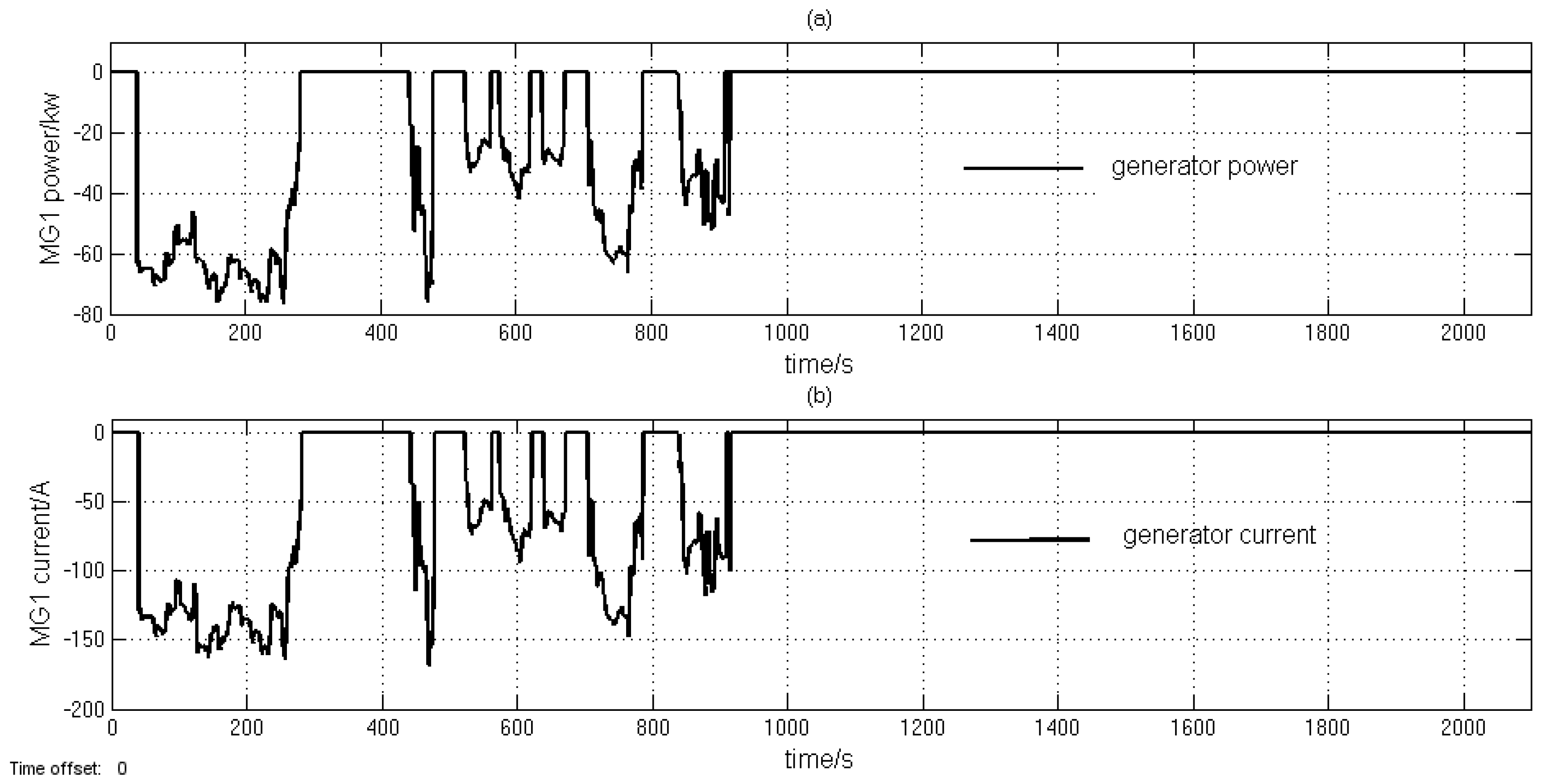
The engine, generator, and motor used in the coaxial power-split hybrid system are arranged on the same side and coaxial. As described earlier, the designs are more compact than the above hybrid system in Figure 1. The performance of the generator is analyzed, and the calculated results during the given driving cycle are shown in Figure 10, where the negative value denotes generating. The generator works to charge the battery in the hybrid electric mode to make the engine supply the energy when the vehicle is driving on an uphill road. The generator maximum output power is 76.5 kW, and the maximum output current is 168 A, as shown in Figure 10a,b, respectively.
As can be seen from Figure 11a, the output power of the motor varies with the SOC and the external load, where the positive value means MC2 is driving and the negative value denotes MC2 is a generator that recovers the braking energy. The maximum output power of MC2 is 128 kW for discharging and 63 kW for charging. The maximum output current is lower than 320 A, which is in the current limit range, as shown in Figure 11b.
According to the system operation mode and the external load, the battery is selected to be charged or discharged, and the variation of SOC is presented in Figure 12a. When the system is in an all-electric mode, the demanded power is supplied by the battery and SOC is down. If the system operates in HEV mode, the generator can charge the battery and SOC will rise. When the demand torque is large, the system is in HEV + MC2 mode, and the battery supplies the electric energy to drive the motor. If the vehicle speed is high, the system will be in engine drive mode, and SOC is unchanged. However, when the vehicle is in acceleration, the system can work in E + MC2 drive mode and SOC goes down. When the system is in the regenerative mode, the motor can recover the regenerative energy, which will be stored in the battery.
The battery output power varies with the power of MG1 and MC2, where the positive value is for discharging and the negative value is for charging. The results indicate that energy efficiency can be enhanced because the battery can serve as a storage system to recover the braking energy in the hybrid system. As can be seen in Figure 12b, the maximum power is 120 kW for discharging and 63 kW for charging. The maximum charge and discharge power are in the range of the battery rated power, which is 129 kW.
Figure 12c shows the variation of the output current of the battery. The maximum discharging current is 300 A, and the maximum charging current is 182 A. They are all in the range of the maximum charge and discharge current and less than the rated current. The rated charge and discharge current of the battery pack is 275 A because the charge and discharge rate is 5 C and the peak charge and discharge current is 440 A.
5.2. Fuel Economy Comparison with THS and Mechanical Transmission System
The fuel economy of the conventional mechanical system and THS during the same driving cycle is analyzed to evaluate the proposed coaxial power-split hybrid system. The parameters of various components for the mechanical vehicle are the same as values in Table 3. The engine equipped with the mechanical vehicle is also an 8.4-L YC6L330-42 engine manufactured by the Yuchai company, which is the same as the engine used in the hybrid vehicle. The transmission is selected as a six-speed transmission produced by Allison Transmission. The parameters of the THS are exactly same as the proposed hybrid system. The fuel consumptions of the three systems are calculated, as shown in Table 4. The equivalent fuel consumption of the coaxial power-split hybrid system (considering the electrical energy loss) is 55.34 L/100 KM, where the value is approximately 77.75 L/100 KM for the mechanical vehicle and 60.29 L/100 KM for the THS. Therefore, the fuel consumption of the proposed hybrid system can be reduced by 22.45% and 8.21%, respectively.
The coaxial power-split hybrid system can reduce the fuel consumption during the given driving cycle because of the improvement of energy efficiency. The engine’s working points for the hybrid system and THS are estimated in Figure 13a,b, respectively. Compared to THS in Figure 13b, it is observed that the engine working points are not located in the low-load region when the engine speed is between 800 r/min and 1050 r/min. Meanwhile, the engine speed can rise to more than 1800 r/min when the vehicle speed is high.
In this paper, the engine used in the proposed coaxial power-split hybrid system is the same as that of the mechanical system. According to the previous analysis, the rated power of the engine for the proposed coaxial power-split hybrid system can be decreased by 20%.
6. Conclusions
A coaxial power-split hybrid system is proposed for a mining truck to meet the dynamic characteristics and economy efficiency according to the given driving cycle in this paper. Subsequently, the mathematical model and simulation model are built. A rule-based control strategy is designed. Compared with the performance of THS and the mechanical vehicle system, the economic efficiency of the proposed hybrid system is superior to THS and the conventional mechanical system. In summary, the conclusions of this paper are as follows:
- The proposed hybrid system could operate in six operating modes and can then enhance the fuel efficiency of the vehicle by optimizing the engine working points and recovering the braking energy.
- Regarding the presence of the clutch, the engine can drive the truck directly in high-speed conditions. When the clutch switches between different states, the power interruption will not occur due to the presence of the motor. Both safety and comfort can be enhanced.
- The engine, MG1, and MC2 are arranged on the same side to reduce the axial size and are maintained easily.
- The size and the rated power of the engine can be decreased further to reduce fuel consumption. In contrast to THS and the mechanical vehicle system, the fuel efficiency can be enhanced by 8.21% and 22.45%, respectively.
In this paper, the results prove that the proposed hybrid system using a rule-based control strategy can enhance the fuel economy of the vehicle significantly. Due to the limitation of the causal rule-based strategy, the potential optimal fuel economy of the three system architectures still need to be investigated. Dynamic programming will be adopted in future studies. At present, the cost of motors and batteries is quite high, which impedes the large-scale application of hybrid vehicles. To reduce the cost, a high-speed motor can be applied, and the gear ratios of the planetary gears should be optimized.
Acknowledgments
The authors are grateful for the support by the Ministry of Science and Technology of China (No. 2011AA060404), the China Scholarship Council (No. 201706460069), and the University of Technology Sydney.
Author Contributions
J.Y. and N.Z. conceived and designed the experiments; J.Y. and W.Y. performed the experiments; W.Y. and J.L. analyzed the data; J.Y. and N.Z. contributed analysis tools; W.Y. and J.L. wrote the paper. All authors were involved in the discussion of the results and manuscript.
Conflicts of Interest
The authors declare no conflict of interest.
References
- Sahoo, L.K.; Bandyopadhyay, S.; Banerjee, R. Energy performance of dump trucks in opencast mine. In Proceedings of the 23rd International Conference on Efficiency, Cost, Optimization, Simulation and Environmental Impact of Energy System (ECOS), Lausanne, Switzerland, 14–17 June 2010. [Google Scholar]
- Intergovernmental Panel on Climate Change. Climate Change 2014: Mitigation of Climate Change; Cambridge University Press: New York, NY, USA, 2015; Volume 3. [Google Scholar]
- Lü, C.; Guoqiang, W.; Xinxing, T.; Chunran, L.; Tao, Y. Optimization of power matching on torque-converter with diesel engine for wheel loader. Trans. Chin. Soc. Agric. Mach. 2010, 7, 5. [Google Scholar]
- Brown, G.M.; Elbacher, B.J.; Koellner, W.G. Increased productivity with AC drives for mining excavators and haul trucks. In Proceedings of the Conference Record of the 2000 IEEE Industry Applications Conference, Rome, Italy, 8–12 October 2000; Volume 1, pp. P28–P37. [Google Scholar]
- Mirzaei, S.; Fernandez, A. Retard system solution on electric mining trucks. In Proceedings of the 2012 IEEE Symposium on Sensorless Control for Electrical Drives (SLED), Milwaukee, WI, USA, 21–22 September 2012; pp. 1–5. [Google Scholar]
- Gao, D.; Zhang, W.; Shen, A.; Wang, Y. Parameter Design and Energy Control of the Power Train in a Hybrid Electric Boat. Energies 2017, 10, 1028. [Google Scholar] [CrossRef]
- Bottiglione, F.; Contursi, T.; Gentile, A.; Mantriota, G. The fuel economy of hybrid buses: The role of ancillaries in real urban driving. Energies 2014, 7, 4202–4220. [Google Scholar] [CrossRef]
- Millo, F.; Rolando, L.; Fuso, R.; Zhao, J. Development of a new hybrid bus for urban public transportation. Appl. Energy 2015, 157, 583–594. [Google Scholar] [CrossRef]
- Wu, G.; Zhang, X.; Dong, Z. Powertrain architectures of electrified vehicles: Review, classification and comparison. J. Frankl. Inst. 2015, 352, 425–448. [Google Scholar] [CrossRef]
- Hu, X.; Murgovski, N.; Johannesson, L.; Egardt, B. Energy efficiency analysis of a series plug-in hybrid electric bus with different energy management strategies and battery sizes. Appl. Energy 2013, 111, 1001–1009. [Google Scholar] [CrossRef]
- Ngo, H.-T.; Yan, H.-S. Configuration synthesis of parallel hybrid transmissions. Mech. Mach. Theory 2016, 97, 51–71. [Google Scholar] [CrossRef]
- Chung, C.-T.; Hung, Y.-H. Energy improvement and performance evaluation of a novel full hybrid electric motorcycle with power split e-CVT. Energy Convers. Manag. 2014, 86, 216–225. [Google Scholar] [CrossRef]
- Wishart, J.D.; Zhou, Y.; Dong, Z. Review, modelling and simulation of two-mode hybrid vehicle architecture. In Proceedings of the 9th International Conference on Advanced Vehicle and Tire Technologies (AVTT), Las Vegas, NV, USA, 4–7 September 2007. [Google Scholar]
- Miller, J.M. Hybrid electric vehicle propulsion system architectures of the e-CVT type. IEEE Trans. Power Electron. 2006, 21, 756–767. [Google Scholar] [CrossRef]
- Liu, J.; Peng, H. Modeling and control of a power-split hybrid vehicle. IEEE Trans. Control Syst. Technol. 2008, 16, 1242–1251. [Google Scholar]
- Wang, Q.; Liu, Y.; Liang, G.; Li, J.; Sun, S.; Chen, G. Development and experimental validation of a novel indirect-expansion solar-assisted multifunctional heat pump. Energy Build. 2011, 43, 300–304. [Google Scholar] [CrossRef]
- Villeneuve, A. Dual mode electric infinitely variable transmission. In Proceedings of the SAE TOPTECH Meeting Continuously Variable Transmission, Detroit, MI, USA, 8–11 March 2004; pp. 1–11. [Google Scholar]
- Ahn, K.; Cho, S.; Lim, W.; Park, Y.; Lee, J.M. Performance analysis and parametric design of the dual-mode planetary gear hybrid powertrain. Proc. Inst. Mech. Eng. Part D J. Automob. Eng. 2006, 220, 1601–1614. [Google Scholar] [CrossRef]
- Cipek, M.; Pavković, D.; Petrić, J. A control-oriented simulation model of a power-split hybrid electric vehicle. Appl. Energy 2013, 101, 121–133. [Google Scholar] [CrossRef]
- Tsai, L.-W.; Schultz, G. A motor-integrated parallel hybrid transmission. In Proceedings of the ASME 2002 International Design Engineering Technical Conferences and Computers and Information in Engineering Conference, Montreal, QC, Canada, 9 September–2 October 2002; pp. 1347–1354. [Google Scholar]
- Ide, H.; Sunaga, Y.; Higuchi, N. Development of SPORT HYBRID i-MMD Control System for 2014 Model Year Accord. Introd. New Technol. 2014, 25, 32–40. [Google Scholar]
- Higuchi, N.; Sunaga, Y.; Tanaka, M.; Shimada, H. Development of a new two-motor plug-in hybrid system. SAE Int. J. Altern. Powertrains 2013, 2, 135–145. [Google Scholar] [CrossRef]
- Ouyang, M.; Zhang, W.; Wang, E.; Yang, F.; Li, J.; Li, Z.; Yu, P.; Ye, X. Performance analysis of a novel coaxial power-split hybrid powertrain using a CNG engine and supercapacitors. Appl. Energy 2015, 157, 595–606. [Google Scholar] [CrossRef]
- Salmasi, F.R. Control strategies for hybrid electric vehicles: Evolution, classification, comparison, and future trends. IEEE Trans. Veh. Technol. 2007, 56, 2393–2404. [Google Scholar] [CrossRef]
- Sciarretta, A.; Guzzella, L. Control of hybrid electric vehicles. IEEE Control Syst. 2007, 27, 60–70. [Google Scholar] [CrossRef]
- Rizzoni, G.; Peng, H. Hybrid and electrified vehicles: The role of dynamics and control. Mech. Eng. 2013, 135, S10. [Google Scholar]
- Lin, C.-C.; Peng, H.; Grizzle, J.W.; Kang, J.-M. Power management strategy for a parallel hybrid electric truck. IEEE Trans. Control Syst. Technol. 2003, 11, 839–849. [Google Scholar]
- Kim, N.; Cha, S.; Peng, H. Optimal control of hybrid electric vehicles based on Pontryagin’s minimum principle. IEEE Trans. Control Syst. Technol. 2011, 19, 1279–1287. [Google Scholar]
- Kim, N.; Cha, S.W.; Peng, H. Optimal equivalent fuel consumption for hybrid electric vehicles. IEEE Trans. Control Syst. Technol. 2012, 20, 817–825. [Google Scholar]
- Wang, E.; Guo, D.; Yang, F. System design and energetic characterization of a four-wheel-driven series—Parallel hybrid electric powertrain for heavy-duty applications. Energy Convers. Manag. 2015, 106, 1264–1275. [Google Scholar] [CrossRef]
- Zhu, F.; Chen, L.; Yin, C. Design and analysis of a novel multimode transmission for a HEV using a single electric machine. IEEE Trans. Veh. Technol. 2013, 62, 1097–1110. [Google Scholar] [CrossRef]
- Liang, J.; Yang, H.; Wu, J.; Zhang, N.; Walker, P.D. Shifting and power sharing control of a novel dual input clutchless transmission for electric vehicles. Mech. Syst. Signal Process. 2018, 104, 725–743. [Google Scholar] [CrossRef]
- Odeim, F.; Roes, J.; Heinzel, A. Power management optimization of an experimental fuel cell/battery/supercapacitor hybrid system. Energies 2015, 8, 6302–6327. [Google Scholar] [CrossRef]
- Hu, H.; Zou, Z.; Yang, H. On-Board Measurements of City Buses with Hybrid Electric Powertrain, Conventional Diesel and LPG Engines; SAE: San Antonio, TX, USA, 2009. [Google Scholar]
- Liang, J.; Yang, H.; Wu, J.; Zhang, N.; Walker, P.D. Power-on shifting in dual input clutchless power-shifting transmission for electric vehicles. Mech. Mach. Theory 2018, 121, 487–501. [Google Scholar] [CrossRef]
- Wang, X.; Chow, J.C.; Kohl, S.D.; Percy, K.E.; Legge, A.H.; Watson, J.G. Real-world emission factors for Caterpillar 797B heavy haulers during mining operations. Particuology 2016, 28, 22–30. [Google Scholar] [CrossRef]
Figure 1.
Existing architectures of the hybrid system: (a) Toyota Hybrid System (THS), (b) CHS hybrid system, (c) Renault IVT system, (d) GM-Allison AHS, (e) Sport hybrid I-MMD system, (f) a coaxial power-split hybrid powertrain proposed by Minggao Ouyang.
Figure 1.
Existing architectures of the hybrid system: (a) Toyota Hybrid System (THS), (b) CHS hybrid system, (c) Renault IVT system, (d) GM-Allison AHS, (e) Sport hybrid I-MMD system, (f) a coaxial power-split hybrid powertrain proposed by Minggao Ouyang.

Figure 2.
Structure of the proposed hybrid system for a mining truck, where, MG1 is the generator; MC2 is the motor.
Figure 2.
Structure of the proposed hybrid system for a mining truck, where, MG1 is the generator; MC2 is the motor.

Figure 3.
Flowchart of the proposed rule-based energy management control strategy, where, V is vehicle speed, P_dmd is demand power, P_bat is battery power, P_eng_opt is optimal engine power, P_eng_min is minimum engine power.
Figure 3.
Flowchart of the proposed rule-based energy management control strategy, where, V is vehicle speed, P_dmd is demand power, P_bat is battery power, P_eng_opt is optimal engine power, P_eng_min is minimum engine power.

Figure 4.
Operating modes of the coaxial power-split system: (a) No. 1, (b) No. 2 and 8, (c) No. 3, 4 and 5, (d) No. 7 in Table 2.
Figure 4.
Operating modes of the coaxial power-split system: (a) No. 1, (b) No. 2 and 8, (c) No. 3, 4 and 5, (d) No. 7 in Table 2.

Figure 5.
Flowchart of the rule-based energy management control strategy for THS.

Figure 6.
Two-parameter dynamic gear shifting strategy.

Figure 7.
The typical driving cycle of the mining trucks: (a) variation of the speed with time; (b) variation of the slope with time; (c) variation of the load with time.
Figure 7.
The typical driving cycle of the mining trucks: (a) variation of the speed with time; (b) variation of the slope with time; (c) variation of the load with time.

Figure 8.
The requested power, speed, and torque of the engine: (a) variation of engine speed with time; (b) variation of engine torque with time; (c) variation of demand power and engine power with time.
Figure 8.
The requested power, speed, and torque of the engine: (a) variation of engine speed with time; (b) variation of engine torque with time; (c) variation of demand power and engine power with time.

Figure 9.
The system operating modes.

Figure 10.
Analysis results of the generator (MG1): (a) variation of MG1 power with time; (b) variation of MG1 current with time.
Figure 10.
Analysis results of the generator (MG1): (a) variation of MG1 power with time; (b) variation of MG1 current with time.

Figure 11.
Analysis results of the motor (MC2): (a) variation of MC2 power with time; (b) variation of MC2 current with time.
Figure 11.
Analysis results of the motor (MC2): (a) variation of MC2 power with time; (b) variation of MC2 current with time.

Figure 12.
Analysis results of the battery system: (a) variation of SOC with time; (b) variation of battery power with time; (c) variation of battery current with time.
Figure 12.
Analysis results of the battery system: (a) variation of SOC with time; (b) variation of battery power with time; (c) variation of battery current with time.

Figure 13.
The engine working points: (a) denotes the proposed hybrid system, (b) denotes THS.


Table 1.
Parameters of various components for the proposed hybrid system.
| Component | Parameter | Value |
|---|---|---|
| Engine | Rated power at speed | 243 kW at 2200 r/min |
| Maximum torque at speed | 1282 Nm at 1400 r/min | |
| Speed range | 0–2200 r/min | |
| Generator/MG1 | Rated/Peak power | 80 kW/80 kW |
| Maximum torque | 400 Nm/400 Nm | |
| Rated speed | 1910 r/min | |
| Speed range | 0–4000 r/min | |
| Motor/MC2 | Rated/Peak power | 120 kW/200 kW |
| Maximum torque | 1146 Nm/1910 Nm | |
| Rated speed | 1000 r/min | |
| Speed range | 0–8000 r/min | |
| Battery | Capacity | 55 Ah |
| Rated voltage | 470 v | |
| Gear ratio | First and second planetary gear | 3.5 |
Table 2.
The operating modes for the system.
| No. | Operating Mode | Clutch | MC2 | MG1 | Engine | Battery |
|---|---|---|---|---|---|---|
| 1 | Electric motor drive | disengaged | drive | zero torque | stop | discharge |
| 2 | HEV Drive (charge) | disengaged | (regenerate) | generate | run | charge |
| 3 | Engine Drive (charge) | engaged | (regenerate) | zero torque | run | charge |
| 4 | Engine Drive | engaged | zero torque | zero torque | run | - |
| 5 | Engine Drive (assist) | engaged | (drive) | zero torque | run | discharge |
| 6 | Sailing | disengaged | zero torque | zero torque | stop | - |
| 7 | Brake | disengaged | regenerate | zero torque | stop | charge |
| 8 | HEV Drive (assist) | disengaged | (drive) | generate | run | discharge |
Table 3.
The technical parameters of the mining truck.
| Parameter | Value | Unit |
|---|---|---|
| Curb masses of vehicle | 28,000 | Kg |
| Laden masses | 20,000 | Kg |
| Rolling resistance coefficient | 0.012 | - |
| Rolling radius | 0.734 | m |
| Final gear ratio | 11.48 | - |
Table 4.
Comparison of the fuel economy.
| Road Spectrum | System | Amount of Fuel Consumption (L) | Fuel Consumption (L/100 KM) | Energy Reduction (%) |
|---|---|---|---|---|
| Typical driving cycle | Mechanical | 8.29 | 77.75 | 22.45 |
| THS | 7.03 | 60.29 | 8.21 | |
| Novel hybrid system | 6.45 | 55.34 | - |
© 2018 by the authors. Licensee MDPI, Basel, Switzerland. This article is an open access article distributed under the terms and conditions of the Creative Commons Attribution (CC BY) license (http://creativecommons.org/licenses/by/4.0/).
Share and Cite
MDPI and ACS Style
Yang, W.; Liang, J.; Yang, J.; Zhang, N. Investigation of a Novel Coaxial Power-Split Hybrid Powertrain for Mining Trucks. Energies 2018, 11, 172. https://doi.org/10.3390/en11010172
AMA Style
Yang W, Liang J, Yang J, Zhang N. Investigation of a Novel Coaxial Power-Split Hybrid Powertrain for Mining Trucks. Energies. 2018; 11(1):172. https://doi.org/10.3390/en11010172
Chicago/Turabian StyleYang, Weiwei, Jiejunyi Liang, Jue Yang, and Nong Zhang. 2018. "Investigation of a Novel Coaxial Power-Split Hybrid Powertrain for Mining Trucks" Energies 11, no. 1: 172. https://doi.org/10.3390/en11010172
Note that from the first issue of 2016, this journal uses article numbers instead of page numbers. See further details here.