Abstract
This paper reports the overall thermal performance of a cylindrical parabolic concentrating solar water heater (CPCSWH) with inserting nail type twisted tape (NTT) in the copper absorber tube for the nail twist pitch ratios, 4.787, 6.914 and 9.042, respectively. The experiments are conducted for a constant volumetric water flow rate and during the time period 9:00 a.m. to 15:00 p.m. The useful heat gain, hourly solar energy collected and hourly solar energy stored in this solar water heater were found to be higher for the nail twist pitch ratio 4.787. The above said parameters were found to be at a peak at noon and observed to follow the path of variation of solar intensity. At the start of the experiment, the value of charging efficiency was observed to be maximum, whereas the maximum values of instantaneous efficiency and overall thermal efficiency were observed at noon. The key finding is that the nail twist pitch ratio enhances the overall thermal performance of the CPCSWH.
1. Introduction
In the present era, utilization of solar energy increases with the development of societies as well as the development of solar energy-collected techniques. Cylindrical parabolic concentrating solar water heater (CPCSWH) is one of the techniques that are extensively used in the fields of power generation and some chemical processing industries, due to it has few favorable characteristics, such as high temperature (ranges up to 400 °C and can be obtained due to its higher concentration ratio), ease of maintenance, compact size, and simple design. Huang et al. [1] used a black liquid as working fluid and investigated the thermal performance of a cylindrical parabolic solar collector. They found better thermal performance using black liquid. Heiti and Thodos [2] compared the instantaneous efficiency obtained with and without a coated absorber tube. Their results showed better instantaneous efficiency for the coated absorber tube. Hamad [3] studied the influence of water mass flow rate on the instantaneous efficiency of the cylindrical parabolic solar concentrator. Their result showed that instantaneous efficiency increases with an increase in water mass flow rate. Mullick and Nanda [4] numerically studied the variation in heat loss factors versus absorber tube temperature and absorber diameter. Their results showed that heat loss factors positively change with the absorber tube temperature. Kothdiwala et al. [5] studied the influence of tracking and longitudinal configurations of the compound parabolic concentrating solar collector on the thermal performance. Eskin [6] presented the temperature variations of the absorber, glass envelope and water outlet. Eck and Hirsch [7] conveyed the experimental investigation of a parabolic trough based power generation plant. Kim et al. [8] numerically and experimentally studied the thermal performances of an evacuated compound parabolic concentrator. They compared the experimental results with the numerical results and their results showed that the thermal performance of cylindrical parabolic collector (CPC) in tracking mode was much higher than the same obtained from the non-tracking mode. Oommen and Jayaraman [9] conducted an experiment on a compound parabolic concentrating collector to study steam generation and solar energy collection. Fadar et al. [10] studied the adsorption refrigeration system run by a parabolic trough collector. Padilla et al. [11] studied the heat loss and collector efficiency, numerically. Gang et al. [12] performed the experimental investigation on exergy efficiency and overall thermal efficiency of the compound parabolic collector. Kumaresan et al. [13] studied the overall heat loss coefficient of the storage tank, charging efficiency and overall performance of the parabolic trough collector, experimentally. Their results showed that the charging efficiency is maximal at the beginning of the experiment and overall thermal efficiency increases with hourly solar energy stored. Reddy [14] studied the performance of a solar parabolic trough power plant. Ceylan and Ergun [15] conducted an experimental study of a temperature controlled CPC and reported energy efficiency and exergy efficiency. Jafar and Sivaraman [16] conducted an experiment on a parabolic trough collector to study the influence of nail twisted tape (twist ratios 2 and 3) on thermo-hydraulic performance using Al2O3/water nanofluid. Their results showed that heat transfer was far better for twist ratio 2. Mwesigye et al. [17] investigated the entropy generation caused by fluid friction and heat transfer in the receiver tube. Khanna and Sharma [18] showed the circumferential temperature distribution of the absorber tube of a CPC. Jaramillo et al. [19] found that the thermal performance significantly improves with twisted tape inserts in the absorber tube. Liang et al. [20] used the Monte Carlo Method to analyze the solar flux distribution on the receiver and the optical thermal performance of the parabolic trough collector. Fuqiang et al. [21] investigated and compared the overall heat transfer and thermal strain of the copper absorber tube. Bortolato et al. [22] used a flat bar and plate absorber instead of the circular absorber and they found overall thermal efficiency significantly improved. Zhao et al. [23] used the Monte Carlo Ray Trace method and their result showed circumferential heat flux distribution on the receiver tube. Zou et al. [24] theoretically studied the optical performance of the parabolic trough solar collector. Fraidenraich et al. [25] studied the angular acceptance function of a cylindrical parabolic collector.
From the above literature survey, it has been observed that most researchers have worked on the cylindrical parabolic collector with a plain absorber tube and they determined the thermal performances only. Very few researchers have worked on the parabolic trough collector with an inserted nail twisted tape in the absorber tube and they studied only the hydraulic performance parameters. No researcher studied the thermal performance of the CPCSWH with the inserting nail type twisted tape (NTT) in the absorber tube. In the present experimental study, the influence of a new parameter, namely, the nail twist pitch ratio, on the thermal performance is reported. The main objectives were to study the influence of the nail twist pitch ratio on useful heat gain, hourly solar energy collected and hourly energy stored with the time of the day.
2. Experimental Setup and Procedure
Description of the Experimental Set Up and Experimental Procedure
Details of the CPCSWH experimental setup are shown by a schematic diagram (Figure 1). The schematic of sectional views (front view and side view) of the nail type twisted tape insert in the absorber tube are shown in Figure 2. Figure 3 and Figure 4 show the photographic view of the CPCSWH experimental setup (manufactured by Ecosense Sustainable Solutions Pvt. Ltd. (New Delhi, India), Model: EcoSCTS-2.1) and NTT respectively. The CPCSWH consists of a water storage tank (capacity 28 L), circulating pump, parabolic concentrating reflector (PCR) and copper absorber tube. The PCR is made of acrylic mirror with a highly reflecting surface of reflectivity 0.90 and its focal length is 0.6065 m (rim angle 67.24°). It has a reflecting surface, which consists of parabolic mirrors of 1.018 m2 aperture area each (0.834 m width and 1.220 m length), with a total aperture area of 2.036 m2, which concentrates the incoming solar beam radiation to the absorber tube with a concentration ratio of 20.598. The copper tube is used as a solar radiation receiver with an absorptance of 0.95, which is placed along the focus axis of the concentrating reflector. It is coated with black nickel coating, and is covered by a glass envelope to minimize heat losses through convection and conduction. The glass envelope has the following dimensions: inner diameter, 0.066 m and outer diameter, 0.071 m, with a transmissivity of 0.85. The rubber corks are incorporated at the ends of the glass envelope to achieve an air-tight enclosure. The main function of the absorber tube of a CPCSWH is to absorb the concentrated solar radiation and transfer the concentrated solar radiation to the water flowing through it. A pump pumps water to flow continuously through the absorber tube of the CPCSWH to the water storage tank, and during the flow through the absorber tube, absorbed solar energy transfer takes place from absorber tube to flowing water. A pump regulating knob is used to control the volumetric water flow rate (in L/min). A water flow sensor (model: YF-S201, Seametrics Inc., Kent, WA, USA) is fitted in line with the hydraulic hose pipe (between the pump’s outlet and the inlet of the absorber tube) to measure the volumetric water flow rate. Hydraulic hose pipes are connected between the pump and water flow sensor, water flow sensor and absorber tube inlet, and absorber tube outlet and the water storage tank. The water storage tank is made of stainless steel material and is cylindrical in shape. The water storage tank is insulated with glass wool and covered by a thick, black colour Rexene to prevent heat losses and is placed at the bottom of the cylindrical parabolic reflector. The thermocouples are inserted on the surface of the absorber tube, inside the water storage tank, water storage tank inlet as well as at the inlet and outlet of the absorber tube, to measure the water temperatures at the same locations. A display board, equipped with five numbers as digital temperature indicators (connected with the above-mentioned thermocouple), to indicate the thermocouple’s deflection (i.e., temperature readings), and a water flow rate indicator (connected with water flow sensor) to indicate the volumetric water flow rate. During the experiment, temperatures and water flow rate were recorded from the display board. Two pressure transducers (model: 3100, Setra Systems, Boxborough, MA, USA) are used, in order to measure the pressure at outlet and inlet of the absorber tube. One is placed in the inlet of the absorber tube and the other one is placed at the outlet of the absorber tube. The tracking mechanism consists of an embedded electronic control system. The electronic control system is equipped with a Light Dependent Resistor (LDR), to move the collector with the apparent motion of the sun, so that solar radiation reaches the collector aperture at a 90° angle. The PCR rotates around the horizontal north–south axis, to track the sun as it moves through the sky during the day. The solar intensity is recorded by a pyranometer, connected with a solar power meter (Tenmars TM-207, Tenmars Electronics Co. Ltd., Tapei, Taiwan).
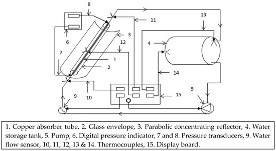
Figure 1.
The schematic diagram of the CPCSWH (cylindrical parabolic concentrating solar water heater) experimental setup.
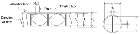
Figure 2.
Schematic sectional views of NTT (nail type twisted tape).
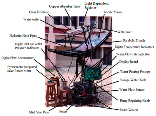
Figure 3.
Photographic view of the CPCSWH experimental setup.
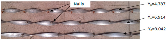
Figure 4.
Photographic view of NTT.
Initially, the experiment was conducted with a plain copper absorber tube and the next experiments were conducted by inserting the NTT into the absorber tube, one by one, with varying nail twist pitch ratios (4.787, 6.914 and 9.042). Aluminium strips were used to manufacture the twisted tape and mild steel headless screws were inserted into the previously drilled holes at a twist pitch distance over the length of the twisted tape. The experiment was conducted from the 25 April of 2017 to June of 2017 and during the time period of 9:00 a.m. to 15:00 p.m. and the experimental works were conducted at Indian Institute of Technology (Indian School of Mines) Dhanbad (latitude 23°47″ N and longitude 86°30″ E), a city situated in the northeast region of India (country), with an elevation of 232.0 m (approx.) above mean sea level (MSL).
The specifications of the CPCSWH experimental set up and NTT are shown in Table 1.

Table 1.
Specifications of the CPCSWH experimental setup and NTT (nail type twisted tape).
3. Data Reduction
The experimental data were used in the below equations to determine the experimental results. The water mass flow rate is calculated using Equation (1), as follows
Useful heat gain is the solar energy absorbed by the circulating water during the flow through the absorber tube and is calculated using the Equation (2), as follows
Bulk mean temperature is calculated using the Equation (3), as follows
Bulk mean temperature of the water in the water storage tank is calculated using the Equation (4), as follows
Hourly solar energy collected is the solar energy gain during a one-hour time interval, as given by Kumaresan et al. [13] and it is calculated using Equation (5), as follows
Hourly solar energy stored is the solar energy stored in the water storage tank during the one hour time interval as given by Kumaresan et al. [13] and it is calculated using Equation (6) as follows
The temperature rise parameter is calculated using the Equation (7), as follows
Instantaneous efficiency is calculated using Equation (8), as follows
The charging efficiency is the ratio of hourly solar energy stored in the water storage tank to hourly solar energy collected, as given by Kumaresan et al. [13]. It is calculated using Equation (9), as follows
The overall system efficiency is the ratio of hourly solar energy stored in the water storage tank to hourly solar energy collected on the parabolic concentrating reflector. It is calculated using Equation (10), as follows
4. Uncertainty Analysis
The method proposed by Kline and McClintock [26] is used for uncertainty calculation. In the experimental measurements, the maximum value of uncertainties was found to be ±3.49% for useful heat gain, ±2.105% for hourly solar energy collected, ±0.9851% for hourly solar energy stored, ±3.389% for the temperature rise parameter, ±4.571% for instantaneous efficiency, ±0.986% for the charging efficiency and ±0.985% for the overall thermal efficiency. The accuracies of the instruments used for uncertainty analyses are shown in Table 2.
Table 2.
Accuracies of the instruments.
5. Results and Discussion
5.1. Solar Intensity with Time
Figure 5 presents the variation of solar intensity with time. From this figure, it is very clear that the slope of solar intensity increases from 9:00 a.m. to 11:00 a.m. and after that its slope increases slowly until noon. The peak values of solar intensity are observed at 12:00 a.m. After 13:00 p.m., the value of solar intensity starts to reduce, with a higher decreasing rate until 15:00 p.m.
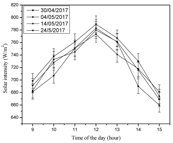
Figure 5.
Variation of solar intensity with time of day.
5.2. Effect of Nail Twist Pitch Ratio on Useful Heat Gain
Figure 6 shows the variation in useful heat gain with time for the plain absorber tube and the absorber tube with NTT inserts. The useful heat gain changes progressively with time, from 9:00 a.m. to 12:00 a.m., and then starts to deteriorate from 12:00 a.m. to 15:00 p.m., as shown in Figure 6. The useful heat gain is maximum at noon when solar intensity is maximum. The variation in useful heat gain follows the path of variation in solar intensity. Also, useful heat gain increases with a smaller nail twist pitch ratio. This is owing to the fact that swirl flow and turbulence are induced by the NTT. Also with a smaller nail twist pitch ratio, the tape twist pitch decreases and the number of nails increase, which, in turn, deeply intensifies swirling and turbulence. The combined effect increases heat transfer time and the rate of heat transfer from the absorber tube to flowing circulating water. Due to this, useful heat gain increases. In the present experimental study, the maximum useful heat gain increased by 12.462% for a nail twist pitch ratio of 4.787, 10.753% for a nail twist pitch ratio of 6.914 and 7.591% for a nail twist pitch ratio of 9.042 than useful heat gain obtained from the plain absorber tube. Therefore, useful heat gain, obtained from the absorber tube with NTT inserts, are found to be much higher than that in the plain absorber tube.
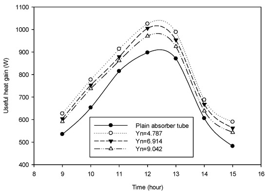
Figure 6.
Variation in useful heat gain with time and nail twist pitch ratio.
5.3. Effect of Nail Twist Pitch Ratio on Water Outlet Temperature and Water Temperature in the Water Storage Tank
Figure 7 indicates the variation of the water outlet temperature with time, whereas Figure 8 indicates the water temperature in the water storage tank with time, for different nail twist pitch ratios (4.787, 6.914 and 9.042). These figures clearly show that the water outlet temperature and water temperature in the water storage tank both change positively with higher incremental rates, from 9:00 a.m. to 12:00 a.m., as solar intensity increases during this time period. From 12:00 a.m. to 15:00 p.m., the water outlet temperature and the water temperature in the water storage tank both increase slowly and the NTT insert absorber tube improves these temperature results. This is due to the fact that the stored water is flowing through the absorber tube to the water storage tank and from the water storage tank to the absorber tube (i.e., a closed-loop system) and hot water, stored in the water storage tank, is entering the absorber tube to absorb the concentrated solar energy from the absorber tube. There is neither fresh water entering into the system, nor energy withdrawing from the system. Stored hot water is being heated again and again, only during the experiment. Also, the water outlet temperature increases for the NTT inserts absorber tube with a smaller nail twist pitch ratio, due to swirl flow and turbulence, created by the tape twist and nail of the NTT inserts absorber tube. Also, the water temperature in the water storage tank is affected by the same influences of the NTT. During the experiment, the maximum water outlet temperature was found to be 77.170 °C for a nail twist pitch ratio of 4.787 at 15:00 p.m. Therefore, it is very transparent that the water temperature in the water storage tank follows the path of variation of the circulating water temperature at the outlet of the absorber tube.
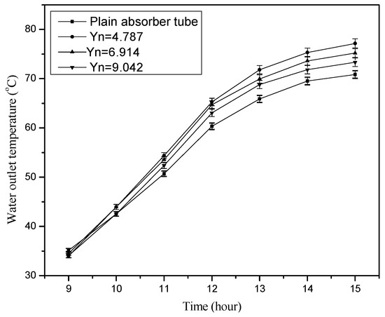
Figure 7.
Variation in water outlet temperature with time and nail twist pitch ratio.
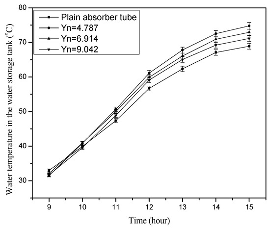
Figure 8.
Variation of water temperature in the water storage tank with time and nail twist pitch ratio.
5.4. Effect of the Nail Twist Pitch Ratio on Hourly Solar Energy Collected
The hourly solar energy collected vs. time is shown in Figure 9. The hourly solar energy collected increases, from 9:00 a.m. to 11:00 a.m., at a faster rate and reaches a peak value at noon. After noon, its value again decreases and reaches a minimum value. From this figure, it is also clearly observed that hourly solar energy collected enhances, with a significantly faster rate from 9:00 a.m. to noon and after noon it begins to decay. Therefore, hourly solar energy collected follows the path of variation of incident solar radiation and useful heat gain. From the present experimental investigation, the maximum values of hourly solar energy collected are observed during the time interval between 12:00 a.m. and 13:00 p.m. Also, the maximum value of hourly solar energy collected was found to be increased by 12.189% for a nail twist pitch ratio of 4.787, 9.770% for a nail twist pitch ratio of 6.914 and 6.733% for a nail twist pitch ratio of 9.042, compared to the same obtained for the plain absorber tube. This is because of the swirl flow and turbulence induced by the NTT inserted absorber tube. The combined effect increases the useful heat gain that, in turn, increases the hourly solar energy collected.
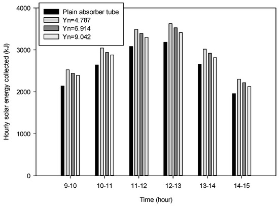
Figure 9.
Variation in hourly solar energy collected with time and nail twist pitch ratio.
5.5. Effect of Nail Twist Pitch Ratio on Hourly Solar Energy Stored in the Water Storage Tank
Figure 10 shows the variation in hourly solar energy stored vs. nail twist pitch ratio and time. From this figure, it is very clear that hourly solar energy collected increases between the time period of 9:00 a.m. and 13:00 p.m. After that, its value decreases, with a faster rate, until 15:00 p.m., as the hot water is heated again and again, so useful heat gain gradually decreases during this time period. Also, hourly solar energy stored increases with decreasing nail twist pitch ratio, as lower nail twist pitch ratios strongly intensify the swirling flow and turbulence in the absorber tube. The combined effect improves the hourly solar energy stored. From the present experimental study, the maximum value of hourly solar energy stored was found to be increased by 11.087% for a nail twist pitch ratio of 4.787, 6.154% for a nail twist pitch ratio of 6.914 and 9.179% for a nail twist pitch ratio of 9.042, compared to the same for the plain absorber tube. Maximum values of hourly solar energy stored are observed during the time interval between 11:00 a.m. and 12:00 a.m.
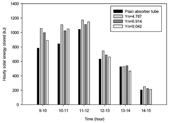
Figure 10.
Variation in hourly solar energy stored with time and nail twist pitch ratio.
5.6. Effect of Nail Twist Pitch Ratio on Temperature Rise Parameter
Figure 11 indicates the variation in temperature rise parameter with time for the nail twist pitch ratios, 4.787, 6.914 and 9.042, respectively. This figure clearly shows that the temperature rise parameter increases with a higher rate, from 9:00 a.m. to 11:00 a.m., as the solar intensity increases and after that, it attains a maximum value at noon. After 13:00 p.m., its value decreases to a minimum value with a faster rate, as storage hot water is circulating through the absorber tube and this results in very little increase in water outlet temperature at the absorber tube. Therefore, the temperature rise parameter decreases and follows the path of variation of solar intensity. Also, the temperature rise parameter increases for the NTT insert absorber tube with a smaller nail twist pitch ratio, as swirl flow and turbulence, created by the tape twist and nail of the NTT inserts absorber tube and the smaller nail twist pitch ratio deeply intensify the swirling and turbulence. From the present experimental study, it has been observed that the maximum value of temperature rise parameter is increased by 13.168% for a nail twist pitch ratio of 4.787, 11.815% for a nail twist pitch ratio of 6.914 and 9.444% for a nail twist pitch ratio of 9.042, compared to the result obtained from the plain absorber tube. Therefore, NTT influences the temperature rise parameter.
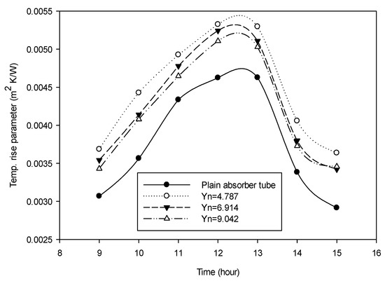
Figure 11.
Variation in the temperature rise parameter with time and nail twist pitch ratio.
5.7. Effect of Nail Twist Pitch Ratio on Instantaneous Efficiency
Figure 12 shows the change in instantaneous efficiency with time for the nail twist pitch ratios: 4.787, 6.914 and 9.042. This figure shows that instantaneous efficiency rises from 9:00 a.m. to 11:00 a.m. and beyond this time its value rises substantially, with a slower rate until noon. After this, its value decreases with time. From this experimental work, it is found that the instantaneous efficiency reaches a peak value of 64.280% for a nail twist pitch ratio of 4.787, 63.299% for a nail twist pitch ratio of 6.914 and 61.639% for a nail twist pitch ratio of 10.106, at noon. The instantaneous efficiency was found to be 55.820% for the plain absorber tube. This is due the fact that water flows through the path directed by the tape twist and turbulence, magnified by the nail of the NTT inserted absorber tube; the combined effect increases useful heat gain. Thus, there is an increase in instantaneous efficiency.
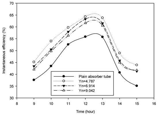
Figure 12.
Variation in instantaneous efficiency with time and nail twist pitch ratio.
5.8. Effect of Nail Twist Pitch Ratio on Charging Efficiency
Figure 13 shows the variation in charging efficiency of the CPCSWH with nail twist pitch ratio and time. In this figure, it is very obvious that at the start of the experiment, the charging efficiency is maximum and then decreases, with a slower rate from 9:00 a.m. to 12:00 a.m. and beyond this time, it decreases at a faster rate. From this figure, it is also clear that smaller nail twist pitch ratio is linked with a higher charging efficiency. In case of NTT inserts in the absorber tube, swirl flow is induced by the tape twist, and turbulence intensifies with the nail. This combined effect increases useful heat gain and thus increases hourly solar energy stored in the water storage tank. From the present experimental study, the maximum overall efficiency has found to be increased by 12.489% for a nail twist pitch ratio of 4.787, 10.508% for a nail twist pitch ratio of 6.914 and 4.333% for a nail twist pitch ratio of 9.042, compared to the same obtained from the plain absorber tube. Therefore, the charging efficiency of the CPCSWH is influenced strongly by nail twist pitch ratio and increases with a decreasing nail twist pitch ratio.
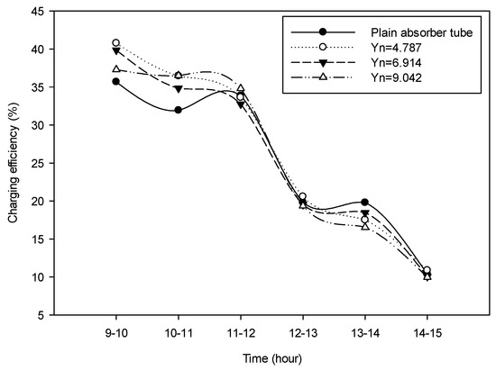
Figure 13.
Variation in charging efficiency with time and nail twist pitch ratio.
5.9. Effect of Nail Twist Pitch Ratio of Overall Thermal Efficiency
Figure 14 shows the variation in overall thermal efficiency of the CPCSWH with nail twist pitch ratio and time. In this figure, it is very obvious that the overall thermal efficiency of CPCSWH increases during the first 3 h of the experiment and after this time, it decreases continuously until 15:00 p.m. The peak values of overall thermal efficiency are observed between the time interval of 11:00 a.m. and 12:00 a.m. From this figure, it is also clear that smaller nail twist pitch ratio leads to a higher overall thermal efficiency. This is due to the swirl flow, induced by tape twist and the greater turbulence, created by the nail of the NTT. The combined effect increases the hourly solar energy stored and hence, increases the overall thermal efficiency. In the present experimental study, the maximum overall efficiency increased by 12.027% for a nail twist pitch ratio of 4.787, 7.697% for a nail twist pitch ratio of 6.914 and 10.697% for a nail twist pitch ratio of 9.042, compared to the same obtained from the plain absorber tube. Therefore, the overall thermal efficiency of the CPCSWH is influenced by nail twist pitch ratio and the smaller nail twist pitch ratio has a stronger influence than the higher nail twist pitch ratio.
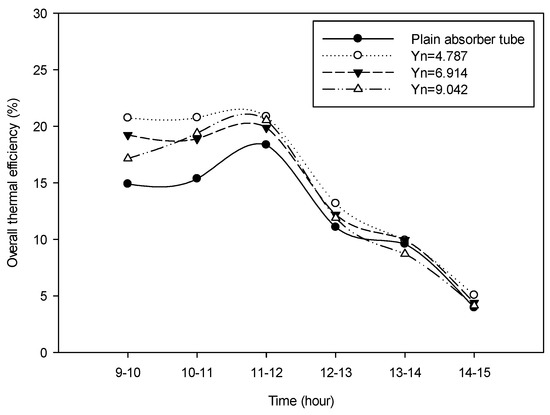
Figure 14.
Variation of overall efficiency with time and nail twist pitch ratio.
6. Conclusions
The solar intensity increases, with a faster rate between the time period of 9:00 a.m. to 11:00 a.m. and reaches to a maximum value at noon and after that it starts decreasing.
Useful heat gain, hourly solar energy collected, the temperature rise parameter and instantaneous efficiency are observed to follow the path of variation of solar intensity. The peak values of these parameters are found at noon when the solar intensity arrives a maximum. A smaller nail twist pitch ratio enhances the above parameters.
The absorber tube water outlet temperature and storage tank water temperature both increase during the time period of 9:00 a.m. to 11:00 a.m. with faster rates and in the period of 12:00 a.m. to 15:00 p.m. with slow rates. The peak value of the absorber tube water outlet temperature and storage tank water temperature are observed at 15:00 p.m.
The maximum values of hourly solar energy collected are found between 12:00 a.m. to 13:00 p.m., whereas hourly solar energy stored is found to be maximum between 11:00 a.m. and 12:00 a.m. Also, a smaller nail twist pitch ratio leads to higher values of hourly solar energy collected and hourly solar energy stored.
The temperature rise parameter, instantaneous efficiency and overall thermal efficiency follow the path of variation of solar intensity. At the beginning of the experiment, the charging efficiency is maximum. A smaller nail twist pitch ratio causes the higher values of the above parameters.
Therefore, the NTT insertion in the absorber tube strongly influences the thermal performance of the Cylindrical Parabolic Concentrating Solar Water Heater.
Author Contributions
Amit K. Bhakta and Shailendra N. Singh conceived and designed the experiments; Amit K. Bhakta performed the experiments and analyzed the data; Amit K. Bhakta and Nitesh K. Panday have been performed uncertainty analysis; Amit K. Bhakta wrote the paper; and Nitesh K. Panday and Shailendra N. Singh have been revised the paper.
Conflicts of Interest
The authors declare no conflict of interest.
Nomenclatures
| Af | Absorber tube flow cross-sectional area (m2) |
| Aap | Reflector aperture area (m2) |
| cp | Specific heat (J·kg−1 °C−1) |
| Di | Absorber tube inner diameter (m) |
| Do | Absorber tube outer diameter (m) |
| dn | Nail diameter (m) |
| Ec | Hourly solar energy collected (kJ) |
| Est | Hourly solar energy stored (kJ) |
| Ib | Solar intensity (W·m−2) |
| Ih | Hourly solar intensity (kJ·m−2 h−1) |
| kf | Thermal conductivity (W·m−1 °C−1) |
| leff | Effective length of nail, leff = (ln − t) (m) |
| ln | Length of nail (m) |
| Lp | absorber tube length (m) |
| m | Mass flow rate of water (kg·s−1) |
| mst | Mass of water in the water storage tank (kg) |
| P | Twist pitch of nail type twisted tape (m) |
| Q | Useful heat gain (W) |
| t | Thickness of nail type twisted tape (m) |
| Tb | Bulk mean temperature (°C) |
| Tb,st | Bulk mean temperature of water in the water storage tank, (°C) |
| Ti | Water inlet temperature (°C) |
| To | Water outlet temperature (°C) |
| Tp | Absorber tube surface temperature (°C) |
| Tst | Water temperature in the water storage tank (°C) |
| TRP | Temp. rise parameter (m2 °C W−1) |
| uf | Velocity of water (m·s−1) |
| Vf | Volumetric water flow rate (m3) |
| w | Width of nail type twisted tape (m) |
| Yn | Nail twist pitch ratio (P leff−1) |
| Greek Symbols | |
| ρf | Density of water (kg·m−3) |
| ηi | Instantaneous efficiency |
| ηch | Charging efficiency |
| ηo | Overall thermal efficiency |
| Abbreviations | |
| CPCSWH | Cylindrical parabolic concentrating solar water heater |
| NTT | Nail type twisted tape |
| PCR | Parabolic concentrating reflector |
| Subscripts | |
| J | At any time interval |
| j + 1 | One hour time interval from jth time |
References
- Huang, B.J.; Wung, T.Y.; Nieh, S. Thermal analysis of black liquid cylindrical parabolic collector. Sol. Energy 1979, 22, 221–224. [Google Scholar] [CrossRef]
- Heiti, R.V.; Thodos, G. An experimental parabolic cylindrical concentrator: Its construction and thermal performance. Sol. Energy 1983, 30, 483–485. [Google Scholar] [CrossRef]
- Hamad, F.A.W. The performance of a cylindrical parabolic solar concentrator. Energy Convers. Manag. 1988, 28, 251–256. [Google Scholar] [CrossRef]
- Mullick, S.C.; Nanda, S.K. An improved technique for computing the heat loss factor of a tubular absorber. Sol. Energy 1989, 42, 1–7. [Google Scholar] [CrossRef]
- Kothdiwala, A.F.; Norton, B.; Eames, P.C. The effect of variation of angle of inclination on the performance of low-concentration-ratio compound parabolic concentrating solar collectors. Sol. Energy 1995, 55, 301–309. [Google Scholar] [CrossRef]
- Eskin, N. Transient performance analysis of cylindrical parabolic concentrating collector comparison with experimental results. Energy Convers. Manag. 1999, 40, 175–191. [Google Scholar] [CrossRef]
- Eck, M.; Hirsch, T. Dynamics and control of parabolic trough collector loops with direct steam generation. Sol. Energy 2007, 81, 268–279. [Google Scholar] [CrossRef]
- Kim, Y.; Han, G.; Seo, T. An evaluation on thermal performance of CPC solar collector. Int. Commun. Heat Mass Transf. 2008, 35, 446–457. [Google Scholar] [CrossRef]
- Oommen, R.; Jayaraman, S. Development and performance analysis of compound parabolic solar concentrators with reduced gap losses oversized reflector. Energy Convers. Manag. 2001, 42, 1379–1399. [Google Scholar] [CrossRef]
- El Fadar, A.; Mimet, A.; Perez-Garcia, M. Modeling and performance study of a continuous adsorption refrigeration system driven by parabolic trough solar collector. Sol. Energy 2009, 83, 850–861. [Google Scholar] [CrossRef]
- Padilla, R.V.; Demirkaya, G.; Goswami, D.Y.; Stefanakos, E.; Rahman, M.M. Heat transfer analysis of parabolic trough solar receiver. Appl. Energy 2011, 88, 5097–5110. [Google Scholar] [CrossRef]
- Gang, P.; Guiqiang, L.; Xi, Z.; Jie, J.; Yuehong, S. Experimental study and exergetic analysis of a CPC-type solar water heater system using higher-temperature circulation in winter. Sol. Energy 2012, 86, 1280–1286. [Google Scholar] [CrossRef]
- Kumaresan, G.; Sridhar, R.; Velraj, R. Performance studies of a solar parabolic trough collector with a thermal energy storage system. Energy 2012, 47, 395–402. [Google Scholar] [CrossRef]
- Reddy, K.S.; Ravi Kumar, K. Solar collector field design and viability analysis of stand-alone parabolic trough power plants for Indian conditions. Energy Sustain. Dev. 2012, 16, 456–470. [Google Scholar] [CrossRef]
- Ceylan, I.; Ergun, A. Thermodynamic analysis of a new design of temperature controlled parabolic trough collector. Energy Convers. Manag. 2013, 74, 505–510. [Google Scholar] [CrossRef]
- Syed Jafar, K.; Sivaraman, B. Thermal performance of solar parabolic trough collector using nanofluid and the absorber with nail twisted tapes inserts. Int. Energy J. 2014, 14, 189–198. [Google Scholar]
- Mwesigye, A.; Ochende, T.B.; Meyer, J.P. Minimum entropy generation due to heat transfer and fluid friction in a parabolic trough receiver with non-uniform heat flux at different rim angles and concentration ratios. Energy 2014, 73, 606–617. [Google Scholar] [CrossRef]
- Khanna, S.; Sharma, V. Effect of number of supports on the bending of absorber tube of parabolic trough concentrator. Energy 2015, 93, 1788–1803. [Google Scholar] [CrossRef]
- Jaramillo, O.A.; Borunda, M.; Velazquez-Lucho, K.M.; Robles, M. Parabolic trough solar collector for low enthalpy processes: An analysis of the efficiency enhancement by using twisted tape inserts. Renew. Energy 2016, 93, 125–141. [Google Scholar] [CrossRef]
- Liang, H.; You, S.; Zhang, H. Comparison of three optical models and analysis of geometric parameters for parabolic trough solar collectors. Energy 2016, 96, 37–47. [Google Scholar] [CrossRef]
- Fuqiang, W.; Zhexiang, T.; Xiangtao, G.; Jianyu, T.; Huaizhi, H.; Bingxi, L. Heat transfer performance enhancement and thermal strain restrain of tube receiver for parabolic trough solar collector by using asymmetric outward convex corrugated tube. Energy 2016, 114, 275–292. [Google Scholar] [CrossRef]
- Bortolato, M.; Dugaria, S.; Col, D.D. Experimenta study of a parabolic trough solar collector with flat bar-and-plate absorber during direct steam generation. Energy 2016, 116, 1039–1050. [Google Scholar] [CrossRef]
- Zhao, D.; Xu, E.; Wang, Z.; Yu, Q.; Xu, L.; Zhu, L. Influences of installation and tracking errors on the optical performance of a solar parabolic trough collector. Renew. Energy 2016, 94, 197–212. [Google Scholar] [CrossRef]
- Zou, B.; Dong, J.; Yao, Y.; Jiang, Y. A detailed study on the optical performance of parabolic trough solar collectors with Monte Carlo Ray Tracing method based on theoretical analysis. Sol. Energy 2017, 147, 189–201. [Google Scholar] [CrossRef]
- Fraidenraich, N.; de O.P. Filho, M.H.; de C. Vilela, O. A new approach for obtaining angular acceptance function of non-perfect parabolic concentrating collectors. Sol. Energy 2017, 147, 455–462. [Google Scholar] [CrossRef]
- Kline, S.J.; McKlintock, F.A. Describing uncertainties in single-sample experiments. Mech. Eng. 1953, 75, 3–8. [Google Scholar]
© 2018 by the authors. Licensee MDPI, Basel, Switzerland. This article is an open access article distributed under the terms and conditions of the Creative Commons Attribution (CC BY) license (http://creativecommons.org/licenses/by/4.0/).