Article

Analytical Measurements and Efficient Process Generation Using a Dual–Arm Robot Equipped with Electronic Pipettes

1
Institute of Automation, University of Rostock, 18119 Rostock, Germany
2
Center for Life Science Automation (Celisca), University of Rostock, 18119 Rostock, Germany
3
Yaskawa Europe, 85391 Allershausen, Germany
*
Author to whom correspondence should be addressed.
Energies 2018, 11(10), 2567; https://doi.org/10.3390/en11102567
Submission received: 10 August 2018 / Revised: 19 September 2018 / Accepted: 24 September 2018 / Published: 26 September 2018
(This article belongs to the Special Issue Robotics, Micronanosensor and Smart Devices for Control)

Abstract

:
The continued growth in life sciences is being accompanied by the constantly rising demand for robotic systems. Today, bioscreening and high–throughput screening processes are well automated. In contrast, a deficit can be found in the area of analytical measurements with complex and frequently changing processes. Robots undertake not only transportation tasks, but also direct sample manipulation and subsequent analytical measurements. Due to their human-like structure, dual-arm robots perform such processes similar to human operation. Liquid handling is required to transfer chemicals, to prepare standard solutions, or to dilute samples. Two electronic pipettes with different volume ranges (5–200 µL and 50–1000 µL) were integrated into a dual–arm robotic system. The main focus in this publication is the software interface for alternating robot and pipette control as well as the high–level process control system. The performance using a dual–arm robot equipped with electronic pipettes and conventional manual pipettes was determined and compared. The automation system presented is the first integration of a dual-arm robot in analytical measurement processes. Conventional manual laboratory pipettes and electronic pipettes are simultaneously used for liquid-handling tasks. The software control system enables a flexible and user-friendly process generation.

1. Introduction

Bioscreening and high–throughput screening processes are well automated, using conventional transport devices, such as turntables, conveyors, or single–arm articulated robots, for labware transportation and positioning. Cartesian robots with xyz–drives typically perform automated liquid-dispensing processes [1]. Robotic arms with multiple degrees of freedom act as system integrators to connect several stations on the automation system, and the tasks mainly involve transportation and positioning steps [2,3,4].
In contrast, a deficit in automation can be found in the area of analytical measurements with complex and frequently changing processes [4]. A promising solution are dual–arm robots, which are able to move and act in similar way to a human operator due to their structural similarity to humans [5,6,7,8]. Consequently, dual–arm robots act as integrated robots inside an automation system [4]. The most common application areas of dual–arm robots can be found in the automotive and heavy industry for handling and manipulation large–dimension workpieces [9]. The tasks involve not only transportation steps, but also active sample manipulation [4]. Dual–arm robots have gained increasing importance in laboratory automation, especially in the automation of analytical measurement processes, since dual–arm robots are able to perform exactly the same procedure as a human operator with conventional laboratory equipment [2,4].
A wide variety of typical tasks exist in sample preparation processes for analytical measurements, including transportation of sample containers, vessels, vials, and microplates, and opening and closing vessels as well as active sample manipulation, such as pipetting, shaking, cooling/heating, ultrasonic and centrifuge treatment, incubation, measurements, and many more. The dual–arm robot must be equipped with suitable end–effectors to handle numerous labware types, open/close doors, flaps and sample containers, and press buttons [10,11,12,13]. In general, processes using dual–arm robots can be executed in one of three basic operation modes: Non–coordinated operation (each arm executes an own independent process), goal–coordinated operation (both arms execute one process), and coordinated bimanual operation (both arms are necessary to execute one process together) [5]. The coordinated bimanual operation is required to execute pipetting processes using classical manual laboratory pipettes, whereby one arm holds the pipette, and the other arm moves the plunger [10]. The non–coordinated operation mode can be used to handle electronic pipettes [14]. One arm performs the pipetting process, and the second arm may execute another operation.
In the paper presented, a dual–arm robot was integrated into an automation system for sample preparation and analytical measurements. In general, dual–arm robots were used in industrial applications, where a specific process is executed for a long timeframe without significant changes. In contrast, processes in analytical measurements are often changing—sometimes daily. Due to the human–like structure, dual–arm robots are predestinated to perform processes in sample preparation and measurements similar to manual operation. To integrate such robots, a flexible and user–friendly control is required. Laboratory assistants should be able to create robotic tasks without programming knowledge. A new functionality—liquid handling using two electronic pipettes—was integrated. This includes the hardware integration, the implementation of the control software, and the integration into a high–level process control system as well as the system and process optimization.

2. Manual and Automated Liquid Handling

2.1. Overview

Precise aspiration and dispensing, and mixing, as well as transportation, are the main steps in liquid handling. Therefore, a wide variety of pipettes, syringes, needles, and capillaries are available. The liquid volumes typically range from a few nanoliters up to milliliters. Larger liquid amounts are handled using special dispensing systems, whereby the liquid is delivered either with internal or with external liquid reservoirs [15,16,17,18,19,20]. Liquid handling systems involve mechanical and electronic pipettes, automated liquid handling, and dosing systems equipped with single– and multi–channel pipetting or dispensing tools [21]. For automated dilution tasks, special devices have been developed [22,23,24].

2.2. Drawback of Manual Pipetting

Common manual piston–stroke pipettes have a fixed volume or a variable volume ranging typically from 1 µL up to 10,000 µL. Single– and multi–channel designs up to 12 channels are available. Moving a mechanical button up or down causes piston motion and aspiration or dispensing of the liquid.
One drawback of manual pipetting is the repetitive motion of the thumb for moving the button up and down and to hold the pipette in an uncomfortable posture, e.g., if working under an exhaust system. Muscles, tendons, and articular joints of thumb, hand, and wrist are exposed to highly repetitive motion and loading [25,26]. This may result in hand and/or elbow disorders if pipettes are continuously used for more than one hour per day. The shoulders and neck also may be negatively affected by long–term pipetting [27].
The typically unsteady performance of human operators is another drawback. There are strong differences in pipette handling between untrained staff and users with long–term experiences. The operator’s performance may be unstable due to the daily form or fitness, concentration, stress, overexertion, private issues, etc. This may result in pipetting errors, such as unintentional contamination of samples and solutions, and mistakes caused by accidental interchanging of sample vessels.

2.3. Approaches in Automated Liquid Handling

Cartesian robotic systems (xyz–robots) are typical representatives of automated liquid handling systems commercially available [1]. Fast and reproducible liquid handling processes are executed by high–throughput dosing devices integrated in self–contained, rigid workstations with a specified and limited workspace. Additional costs may occur due to type–specific equipment (e.g., pipetting tools, tips, and labware). Open software environments are often provided for the integration of external software modules and existing hierarchical laboratory management systems. Typical tasks are aspiration, dispensing, and mixing; covering and transportation of microplates and sample vessels are additional features. Add–on modules, such as barcode readers, centrifuges, storage elements, incubators, and measurement instruments, can be integrated into the workstations. These modules are usually individually tailored to the system and may cause follow–up costs. Other robotic liquid handling systems use an articulated robotic arm and conventional manual laboratory pipettes integrated into a workstation with a flexible deck layout [28].
Dual–arm robotic systems also can be applied for liquid handling processes if equipped with suitable pipettes. Due to the human–like structure of the robotic arms, conventional manual pipettes can be used [4,10,11,12,13,29,30]. The dual–arm robot performs transportation tasks to connect several stations on the robotic working area and additionally the active manipulation of samples: The robot acts as a flexible robot [4]. For handling manual pipettes, the two robotic arms operate in coordinated bimanual mode: One arm holds the pipette and the second arm presses the button. In highly regulated areas, the use of conventional manual pipettes is essential. The manual and automated processes are identical, and thus avoids renewing the approval of the process. However, there are some disadvantages. The volume adjustment is done by turning a knob and a readout of a mechanical display, which can only be automated with a high sensory effort. To simplify the volume adjustment, a number of pipettes with previously adjusted volumes were provided in the robotic workspace. As a result, transportation and pipetting steps, as well as the processing time, were increased.
In this study, the pipetting process was simplified by the integration of electronic pipettes. The volume can be software controlled and adjusted and the pipette handling is performed using only one robotic arm. The second arm is free for additional processes. The design of the adapter for safe grasping the pipette by the robot and the hardware integration is presented in a previous publication and is only shortly summarized [14]. The focus in this publication is the multi–level software system for robot and pipette control and the integration into a high–level process control system for rapid generation of new pipetting processes using the dual–arm robot.

3. System Concept and System Design

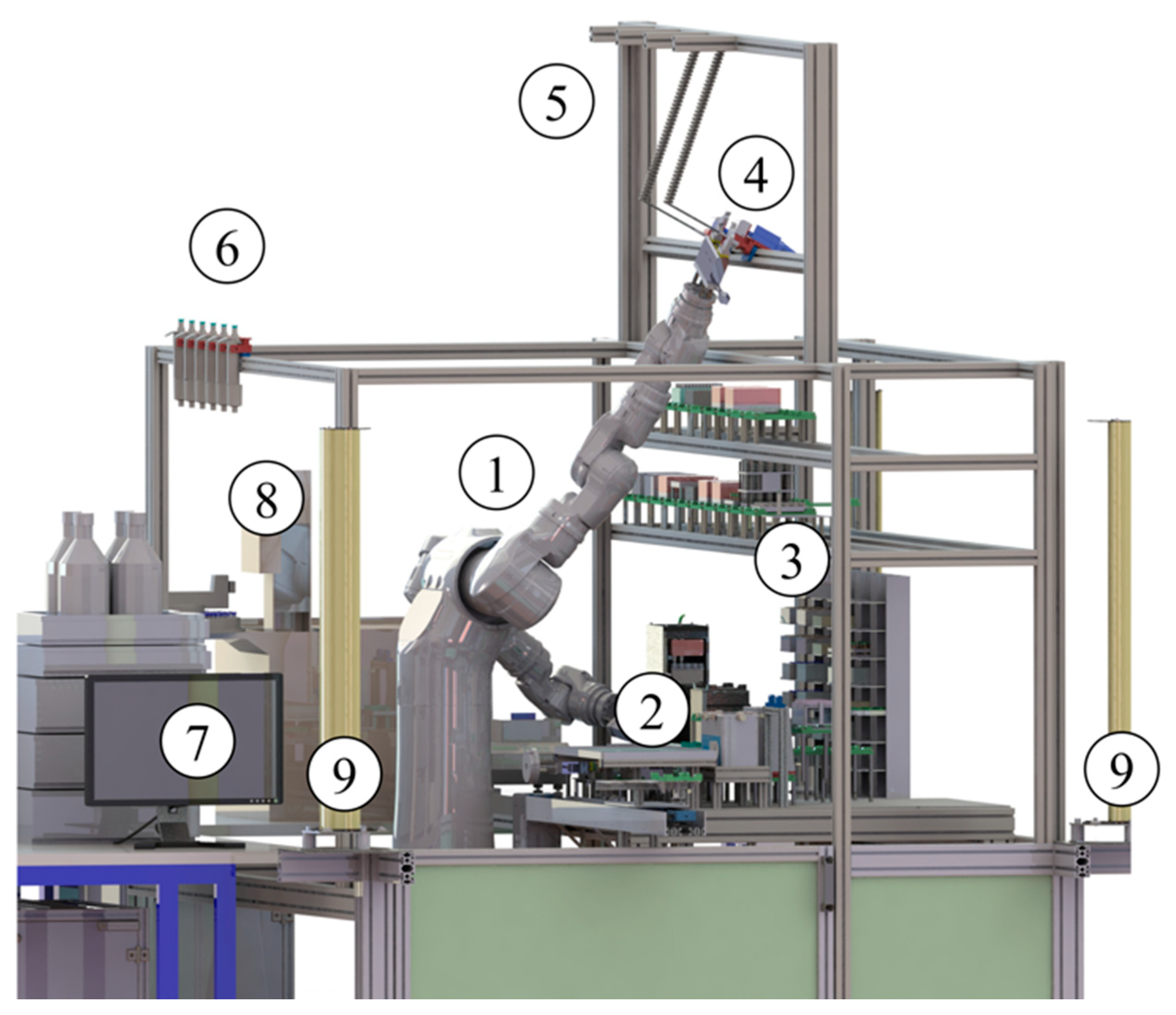
3.1. System Overview

The dual–arm robot, CSDA10F (Yaskawa, Kitakyūshū, Japan), is fix mounted in the automation system and surrounded by a workbench, multi–level storage racks, and two analytical measurement instruments. The samples can be automatically placed into the autosampler units of the liquid chromatography mass spectrometer (LC/MS) and the gas chromatography mass spectrometer (GC/MS) (both Agilent Technologies, Waldbronn, Germany) [4,10,12]. The workbench is equipped with automated labware positioners (ALPs) for exact placing of labware in standardized microplate format. Furthermore, several laboratory devices are mounted on the workbench, including an ultrasonic bath (Bandelin Electronic, Berlin, Germany), a tempered shaker (Eppendorf, Hamburg, Germany), and a non–tempered shaker (Variomag–USA, Daytona Beach, FL, USA). In the upper level, a number of manual piston pipettes (Eppendorf, Hamburg, Germany) and two electronic pipettes, rLine series BRL 200/1 and BRL 1000/1 (Sartorius Biohit Liquid Handling Oy, Helsinki, Finland), are placed for an easy unload by the robot. The volumes of the manual pipettes range from 10 µL up to 10 mL; the electronic pipettes provide volumes of 5–200 µL and 50–1000 µL. The automation cell is surrounded by a safety system consisting of a door switch and a two–side light curtain. The robot is controlled using the control unit, FS100 (Yaskawa, Kitakyūshū, Japan). The measurement instruments are controlled by the software, MassHunter (Agilent Technologies, Waldbronn, Germany). For the high–level process control, each device software was integrated into the process control software, SAMI (Beckman Coulter, Krefeld, Germany), by in-house implemented software interfaces acting as middleware. The middleware for the robot is the software module R–interface. Figure 1 gives an overview of the total robotic automation system.

3.2. Hardware Design

The hardware design for pipette integration was described in detail in a previous publication [14]. Here, the most important parts should be explained, which are required for understanding the software control focused in this paper.
The power supply of the pipettes and the data communication are realized using solid wiring. This concept provides a reliable power supply, ensures a stable communication, and enables a 24/7 operation. In each stadium of operation, the cable must not adversely affect the robot, labware, laboratory devices, and construction parts inside the working area. The pipettes and the stable cable guide are placed in front of the robot above the multi–level storage system. Each pipette is equipped with a gripping adapter for safe grasping and transportation by the dual–arm robot. Currently, two pipettes are integrated; the hardware design allows the operation of a maximum of four pipettes (e.g., with various volume ranges). A hardware interface was developed providing the power supply, the connection between the control computer and interface box via USB, and the connection between the interface box and pipettes via RS232 (see Figure 2).

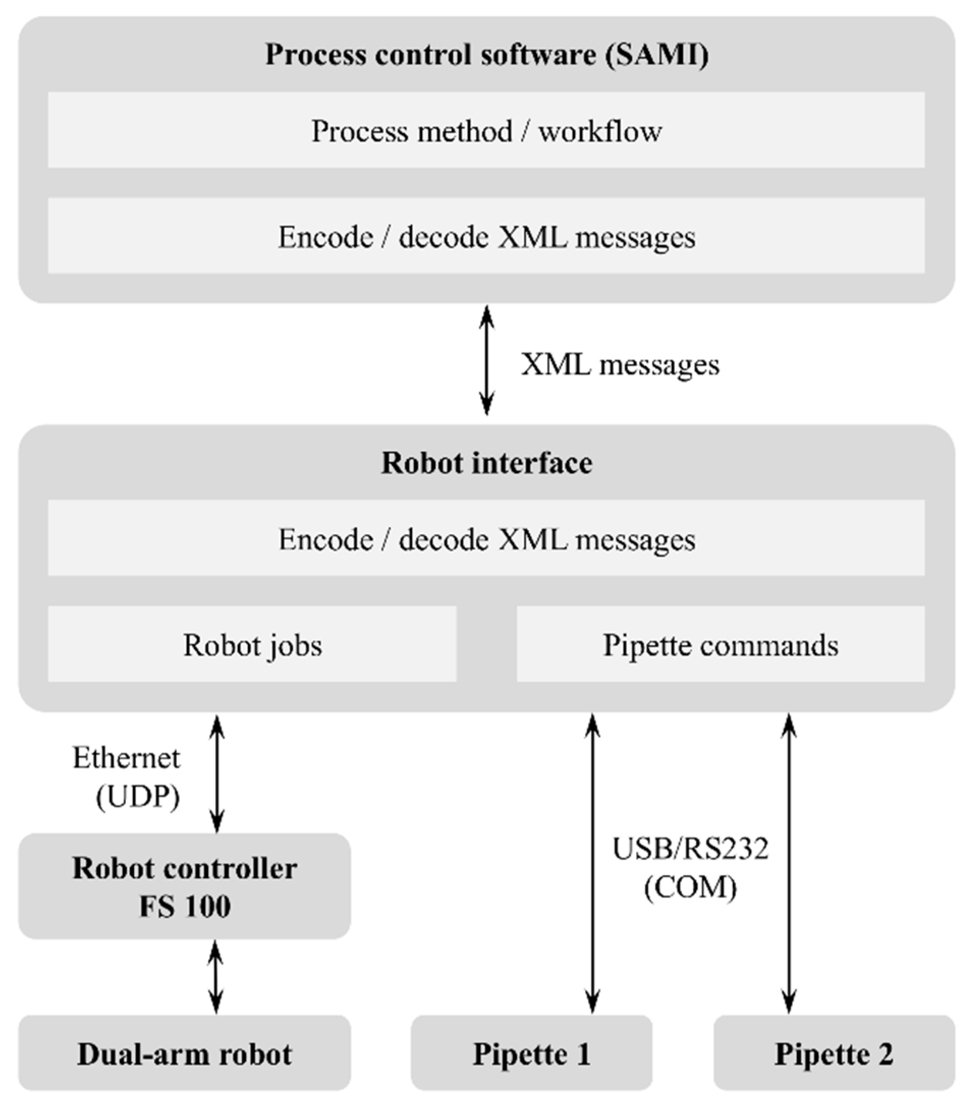
3.3. Software Design

Automated pipetting processes using the dual–arm robot require a suitable combination of pipetting commands and robot motions. The software concept provides an alternating control of the robot and the pipette via a central control computer using USB/RS232 and Ethernet communication. The electronic pipettes are addressed using virtual COM ports assigned by the Windows operation system. The communication is similar to a conventional RS232 interface. The robot jobs are managed by the robot interface software (R–interface). The R–interface is the middleware between the high–level process control software, SAMI (Beckman Coulter, Krefeld, Germany), and the robot control unit, FS100 (Yaskawa, Kitakyūshū, Japan). The communication between SAMI and the R–interface is realized by command and parameter transfer using XML messages. The R–interface encodes/decodes the XML messages and communicates via Ethernet (UDP) with the robot control. The pipetting commands were integrated into the R–interface to realize a sequence control with an alternating call of robot jobs and pipetting commands. A class was implemented, which handles the communication with the electronic pipettes. Figure 3 visualizes the software concept.

4. Pipette Control

The interface software R–interface was created in the programming language C#. To ensure maximum compatibility, the integration of the electronic pipettes into the process control system was realized with a class written in C# for pipette control using commands and queries. For testing and optimization, a separate graphical user interface was created for easy parameter entering.

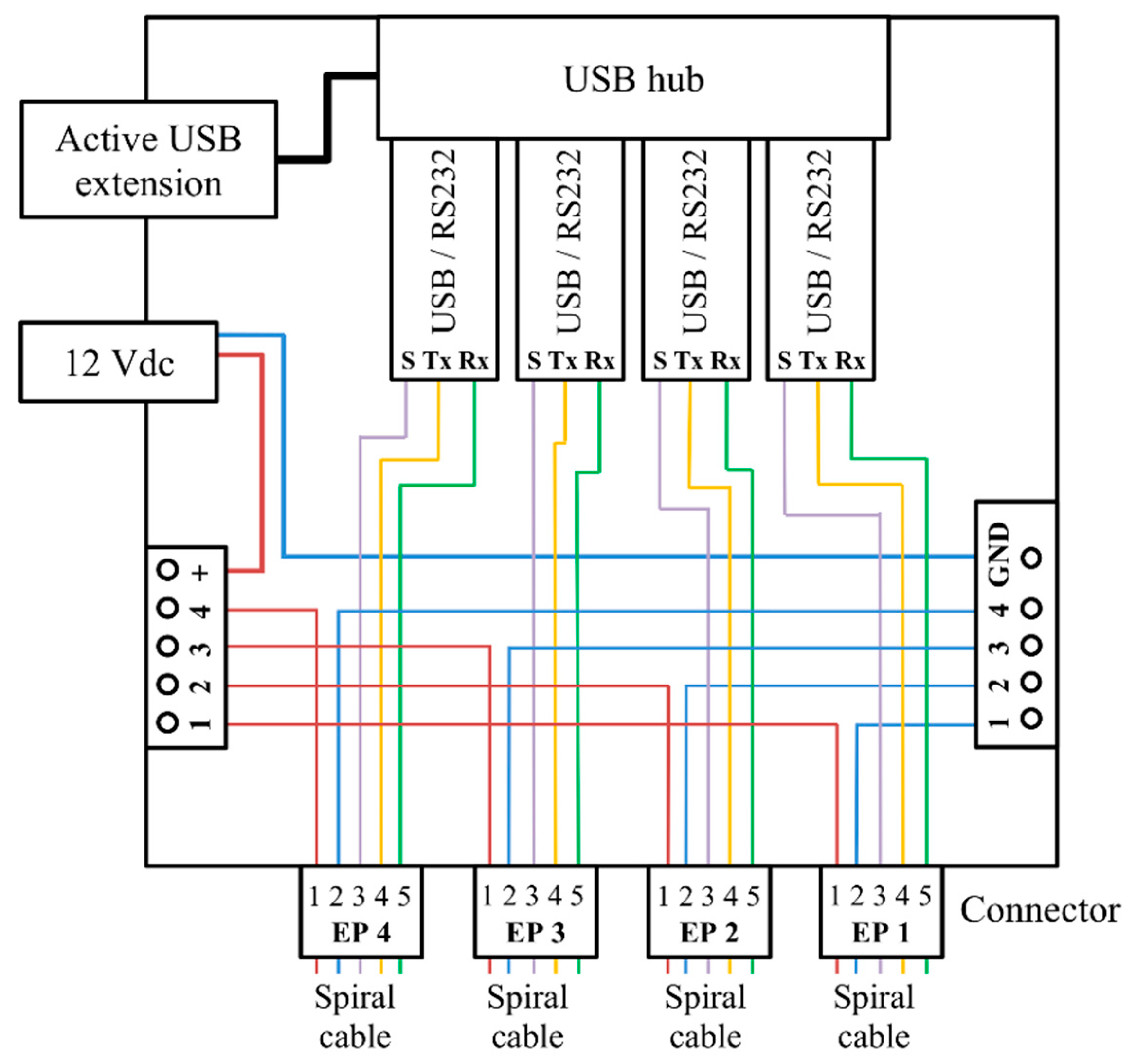
4.1. Communication Protocol

The communication with the rLine pipettes uses the RS232 protocol and the signals, “receive data” (Rx), “transmit data” (Tx) and “signal ground” (SG). The programming environment, Visual Basic (Microsoft, Redmond, US), provides RS232 communication methods using virtual COM ports. The configuration and control of the pipette is performed using messages with commands and queries. Each message contains six components with several functionalities (see Table 1) [31,32].
The messages are created using 7–bit ASCII code. An example should explain a message for a command to move the piston to position “234” (run to position 234). The command is addressed to the pipette with the address “1”. The data part contains the position “234”. The recognition of 1–bit errors during message transmission (longitudinal redundancy check, LRC) is deactivated in this example. Table 2 shows the message structure. The length of the message depends on the length of the component <DATA>. All other blocks have a fixed length. Therefore, the length of the total message may vary between 6 and 9 bytes.

4.2. Pipette Commands

Several types of pipette commands are available for initialization, configuration, and pipetting. A seven–segment angular sensor on the electromechanical driven piston gives position feedback. Prior to pipetting processes, this sensor must be initialized by moving the piston to all possible positions. The properties of the serial data transmission of master (control computer) and slave (pipette) must be identical to ensure a successful communication. Address, baud rate, and LRC state can be reconfigured using configuration commands. Pipetting actions are realized by pipetting commands, e.g., the piston is moved to the desired position with a defined speed. Table 3 gives an overview about pipetting commands and resulting actions.

4.3. Queries

Queries are used to receive pipette information. Some queries are only permissible in standby, such as requesting the pipette version and model, and moving cycles for maintenance, as well as the move–in and move–out speed of the piston. Other queries can be executed in both operation and standby. This includes requesting the module state, error state, and the current piston position.

4.4. Communication Testing

The communication methods using commands and queries were tested with a self–implemented test software, rLine_Com. The graphical user interface (GUI) enables easy parameter entering (see Figure 4). Commands and queries are executed by pressing buttons; values are monitored in text fields. Track bars are used for adjusting the desired values, such as piston positions and speed. After the application start, all available COM ports will be checked. By double clicking of an available COM port, an automated query for the pipette version and model is executed. This enables the pipette identification and port allocation for communication. After selection of the desired pipette, the implemented methods (commands and queries) can be executed and stepwise tested in the target hardware. Typically, the user input is done in units of volume (e.g., µL). A conversion module was implemented to calculate the volume value into steps required by the pipette control. All class methods can be called from other program parts using parameters. This is the prerequisite for the integration into the high–level process control system.

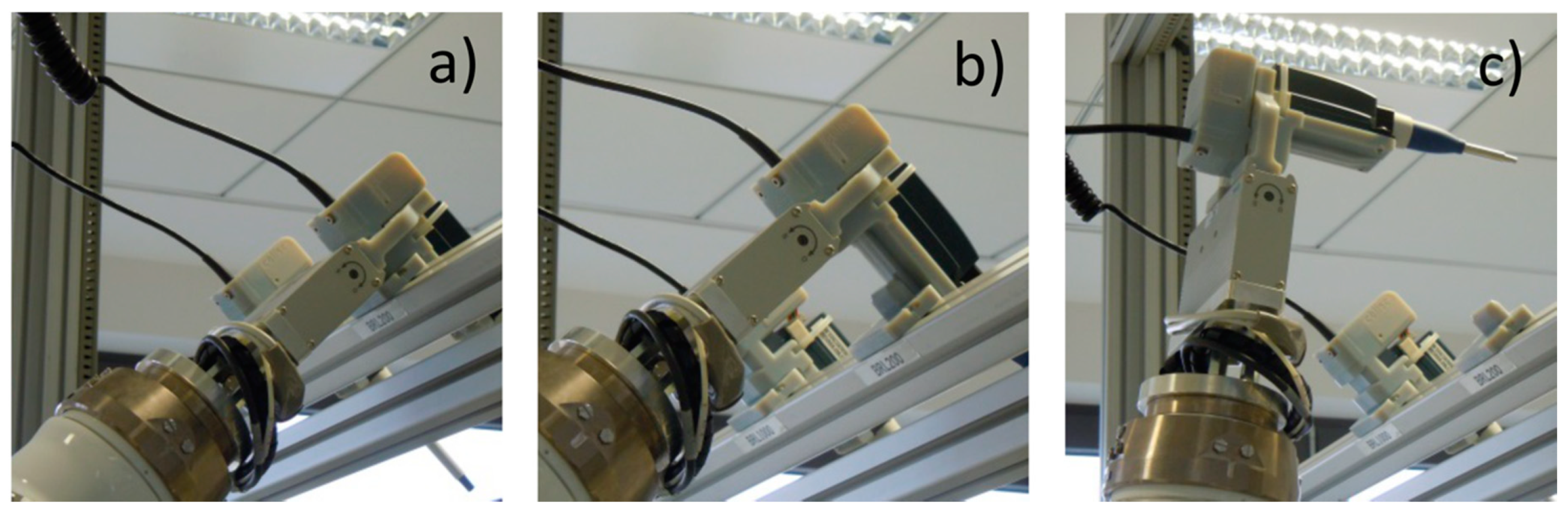
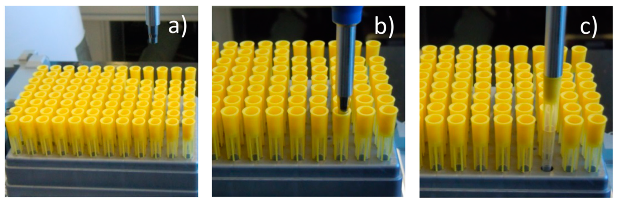
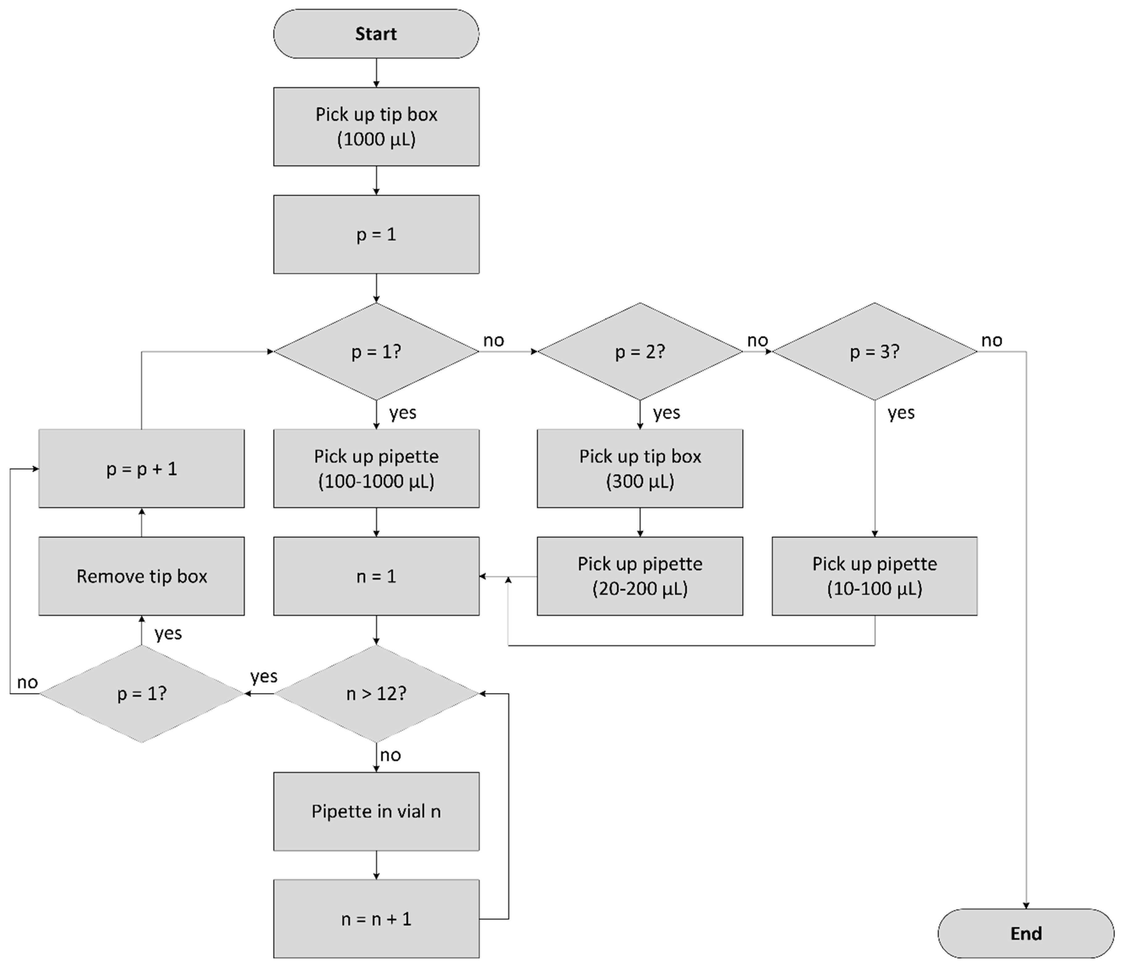
5. Robot Jobs for Pipette Handling

5.1. Robot Jobs

For pipette handling using the dual–arm robot, CSDA10F, several robot jobs have been created. This includes pipette grasping, transportation, placing back and collision avoidance with labware, devices, and constructions of the robot cell. The robot jobs were implemented with the teach–in procedure using the hand programming device as well as by calculations using labware parameters and relative motion parameters [33,34].
All pipetting processes are executed from a safe robot posture to avoid collisions. A combination of robot motions to reach the desired positions and gripper movements is used to grasp a pipette (motion 1) programmed with the teach–in method. The tip load movements (motion 2) are calculated. The pipette tips are stored in racks in microplate format with 96 tips on each rack. In the first step, the local position of the tip to be loaded must be determined. Therefore, the parameters, B043 and B044, are used in a Cartesian coordinate system (see Figure 5).
For pipetting actions (motion 3 and 4), movements into and out from vessels are required, including variables representing the vessel type and the vessel position on the rack. The vessel type determines the immersion depth and speed. The position is given using the variables, B020 and B021, similar to the pipette tip box. The base stations/automated labware positioners (ALPs) for source and destination labware will be defined using the software R–interface and the process control software, SAMI, by parameter transfer. The motion types 2, 3, and 4 are calculated based on the start positions of the robot jobs related to the reference point of the corresponding base station [33,34]. The base station is defined using the variable, B018.
The teach–in method was used to realize the tip drop (motion 5) and placing back the pipette (motion 6) similar to the robot job for pipette pick–up. Table 4 gives an overview of these robot jobs.

5.2. Merging of Robot Jobs and Pipette Commands

The alternating control of the robot and the electronic pipette is a key component of the development of the software interface. The previously explained parts (robot jobs and pipette commands) must be combined in the form of a sequence control. Figure 6 visualizes an exemplary sequence control.
A software module was created inside the R–interface for alternating the sending and receiving of communication messages to/from the pipette and the robot. Table 5 shows the tasks and the related robot jobs and pipetting commands.
After the initialization command to the desired pipette, the pipette is picked–up by the robot using the robot job, EP_XXX_PICKUP. The placeholder, “XXX”, defines the type of the pipette: 200 or 1000. Figure 7 shows a picture series of pipette BRL 200/1 pick–up using the right robotic arm.
For loading the pipette tip, the robot is moved to a safe starting posture above the workbench. The tip load is executed using the robot job, EP_XXX_LOAD, and the required variables for the local tip position (see Figure 5). Simultaneously, the pipette piston is moved to the home position recommended by the manufacturer. Figure 8 shows a picture series of the tip load using the pipette BRL 200/1.
The pipetting procedure uses the robot job, EP_XXX_INTO_VIAL. In the first movement, the robotic arm with the pipette is placed above the desired source labware (e.g., vessel, glass vial etc.). The local position is calculated using variables. In the next step, the robotic arm moves the pipette into the vessel and dips in the liquid. A pipetting command follows and the pipette piston is moved up to aspirate the desired liquid volume. If the aspiration step is finished, the pipette is moved out from the vessel using the robot job, EP_XXX_OUT_VIAL.
The dispensing procedure is similar to the aspiration step and starts with pipette positioning above the destination labware and into the vessel. The pipette piston is then moved down to dispense the liquid. To excess a potential remaining liquid droplet in the tip, the piston is moved up and down a short distance at high speed (blow out). Finally, the pipette is removed from the vessel.
A new pipetting process can be started using the same pipette tip. Alternatively, the tip can be ejected to start a new process with a new tip or to place the pipette back in the holder. For tip ejecting, the robot is moved to the border of the workbench above the waste container (robot job, EP_XXX_TIPEJECT), and the tip is then ejected by the related pipette command. Subsequently, the robot moves back to a safe posture (robot job, EP_XXX_RELOAD) and starts a new pipetting process or places the pipette back in the holder (robot job, EP_XXX_PUTBACK). This sequence control enables a flexible and cyclical execution of pipetting tasks. Figure 9 shows a picture series of various pipetting steps using the pipette, BRL 200/1.

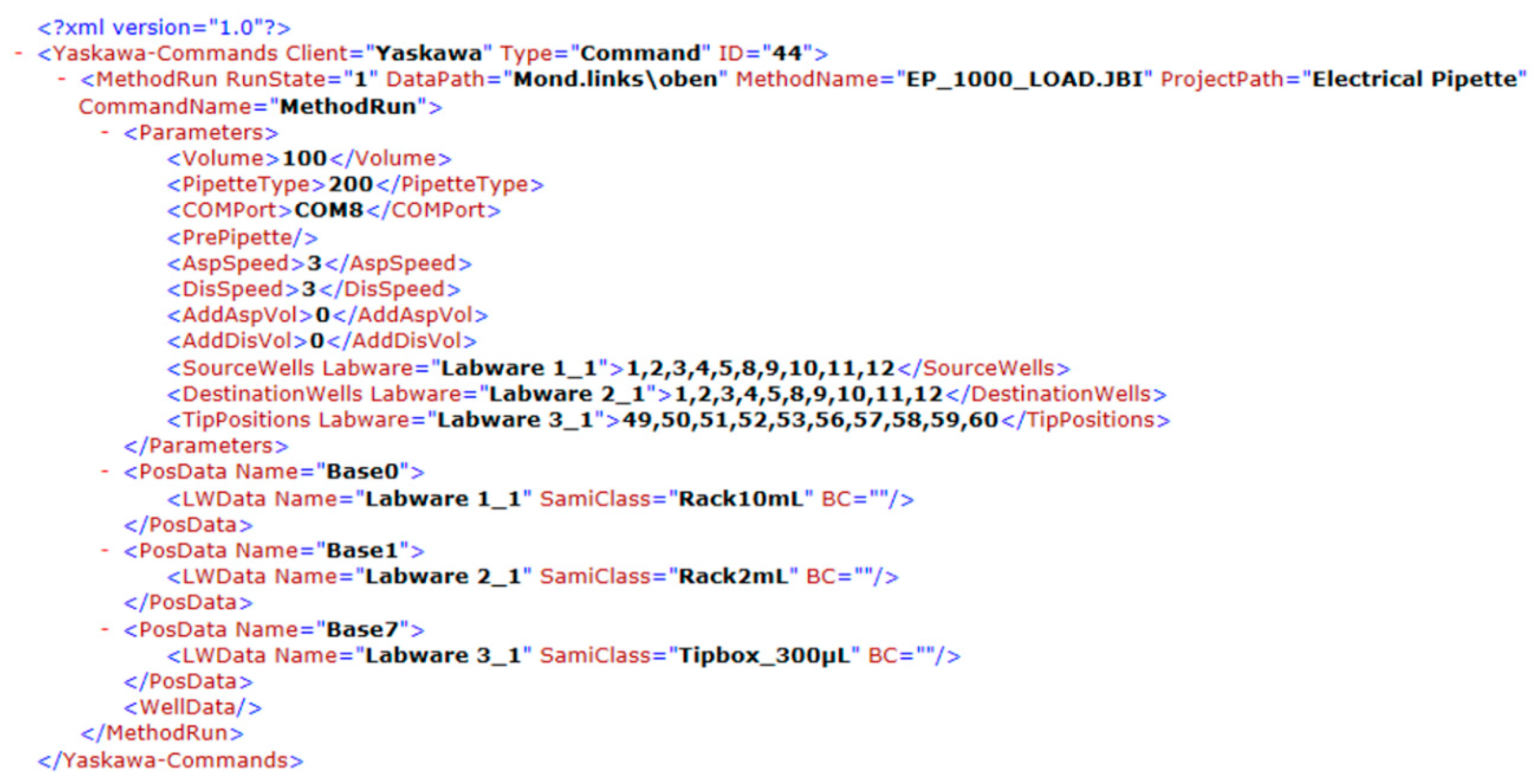
6. High–Level Process Control

A high–level process control system enables remote control of the dual–arm robot and the electronic pipette and—in analytical laboratories, this is an important issue—it provides a tool for an easy generation of new robotic processes without robot programming knowledge. To fulfil these tasks, the dual–arm robot, peripheral devices, such as measurement instruments and the electronic pipettes, were integrated in the process control software, SAMI (Beckman Coulter, Krefeld, Germany). This control software is running on a central computer together with the interface software for the robot (R–interface). A process/workflow will be created in the SAMI editor via a graphical user interface (GUI).

Parameter Transfer Using XML

The process control software, SAMI, and the R–interface communicate using XML messages for parameter transfer for adjusting variables in robot jobs and pipetting commands. Different message types are available, such as “Version”, “Transport”, “MethodRun”, “Resource”, “KeepAlive”, “Abort”, “Stop”, “Continue”, and “Error”. The low–level message format is shown in Table 6.
The software module R–interface has been extended to recognize and evaluate (coding/decoding) the elements and attributes of the XML messages related to pipetting processes. The robot is integrated into the SAMI process per drag and drop and can be controlled using the method, “Run Yaskawa”. Figure 10 exemplarily shows a process in the SAMI editor.
Inside the SAMI method, a new process was added for execution of a complete pipetting process (see Figure 11). The following parameters have to be entered to define the process parameter: Type of pipette, volume, and the COM port for pipette control as well as the speed values for liquid aspiration and dispensing. Furthermore, the properties and positions of the used labware are transferred from the SAMI process to the R–interface. This includes the positions of the pipetting tips, source, and destination labware. For future works, three further parameters were implemented for additional aspiration/dispensing volumes and for special pipetting features (e.g., pre–wet, mixing before/after aspiration/dispensing).
The SAMI process control software uses sequential counting of the tip or vessel positions located at a tip box or a rack. The numbers inside the rack (see Figure 12, inside the circles) represent the position indication in SAMI. The counting starts in the upper left corner and ends in the lower right corner. In contrast, the robot jobs use a two–dimensional Cartesian coordinate system (origin in the upper right corner) and variables are used for position identification. The conversion from one system to another is automatically done in the R–interface. Figure 12 shows the arrangement of vessels on a rack and the two systems of position identification.
The functionality of the communication protocol used between the process control software, SAMI, and the R–interface should be explained with an example message for execution of a pipetting process (see Figure 13). The XML message includes information for robot and pipette control. In the example, 10 pipetting steps are executed for pipetting 100 µL from 10 different source vessels into 10 different destination vessels using the pipette, BRL 200/1, communicating via port COM8. The tip will be changed after each pipetting step. The base stations for the source and destination labware as well as for the tip box must be defined depending on the current arrangement of the workbench. The bases 0, 1, and 7 are used in this example.

7. Results and Discussion

The pipetting precision and the process times were determined using the dual–arm robot equipped with one or more manual pipettes and one electronic pipette. In each experiment, 12 empty GC vials (vol. 2 mL) were numbered and weighted. Ultrapure water was used as the test liquid for aspiration and dispensing. After finishing the pipetting process, the vials were weighted again and the corresponding water volume was calculated. Additionally, the process times required for liquid transfer using manual pipettes and electronic pipettes were recorded. The total process time, including all transportation steps, the time for pipetting from one source vessel into one destination vessel, and the time only for liquid aspiration and for liquid dispensing, were determined.

7.1. Pipetting a Volume of 100 µL

In the first test, a volume of 100 µL was pipetted using a manual pipette with the volume range of 10–100 µL (Eppendorf, Hamburg, Germany) and the electronic pipette, BRL 200/1 (Sartorius Biohit Liquid Handling Oy, Helsinki, Finland). The pipetting processes using one manual and one electronic pipette were identical. The tip box (vol. 300 µL) was transported from the overhead rack to the ALP on the workbench. A volume of 100 µL water was transferred into 12 vials using the manual/electronic pipette. The tip was not changed during this procedure. After liquid transfer, the tip was dropped into the waste, the pipette was placed back on the holder, and the tip box was returned to the overhead rack. The measurement results show average volumes of 97.07 µL for the manual pipette and 95.42 µL for the electronic pipette. The coefficients of variation (CV) reach from 1.44% (manual pipette) to 3.79% (electronic pipette). Table 7 gives an overview of the measurement results.

7.2. Pipetting a Volume of 1300 µL

In the second experiment, a larger volume of 1300 µL was pipetted. Three manual pipettes are required with volume ranges of 10–100 µL, 20–200 µL, and 100–1000 µL. The maximum pipette volumes (100, 200, and 1000 µL) were previously adjusted and the pipettes placed on the holders behind the dual–arm robot. The electronic pipette, BRL 1000/1 (Sartorius Biohit Liquid Handling Oy, Helsinki, Finland), was used in two pipetting steps (1000 µL and 300 µL).

7.2.1. Process Using Manual Pipettes

The tip box (vol. 1000 µL) was transported from the overhead rack to the ALP on the deck area. A volume of 1000 µL of water was transferred into 12 vials using the manual pipette (volume range 100–1000 µL). The tip was not changed during this procedure. After liquid transfer, the tip was dropped into the waste, the pipette placed back on the holder, and the tip box returned to the overhead rack. A second tip box (vol. 300 µL) was transported from the overhead rack to the ALP on the workbench. The procedure was repeated with the next two pipettes to transfer 200 µL and 100 µL. Finally, the tip box was returned to the overhead rack.

7.2.2. Process Using Electronic Pipettes

The tip box with tips (vol. 1000 µL) was transported from the overhead rack to the ALP on the deck area. A volume of 1000 µL water was transferred into 12 vials using the electronic pipette BRL 1000/1. Then the volume was software–based adjusted to 300 µL and water was transferred into the same vials. The tip was not changed during these procedures. After liquid transfer, the tip was dropped into the waste, the pipette was placed back on the holder, and the tip box was returned to the overhead rack.
The measurement results show average volumes of 1276.50 µL for the manual pipette and 1284.17 µL for the electronic pipette. The coefficients of variation (CV) reach from 0.54% (manual pipette) to 0.45% (electronic pipette). Table 8 gives an overview of the measurement results.

7.3. Process Comparison Using Manual and Electronic Pipettes

The comparison of the performance using the manual and the electronic pipette shows no significant differences in the pipetting precision. For pipetting a volume of 100 µL, the CV value using the manual pipette was lower (1.44%) than using the electronic pipette (3.79%). For pipetting a volume of 1300 µL, the CV value was lower using the electronic pipette (0.45%) than using the manual pipette (0.54%). Figure 14 visualizes the measurement results.
The process using manual pipettes requires a high number of pipettes with previously adjusted volumes to realize the final volume. The complexity increases if more pipetting steps are involved. All final volumes must be able to be composed from the provided pipettes and the previously adjusted volumes. This results in a high number of pipettes and much workspace for pipettes and pipette holders as well as a high number of transportation steps for the pick-up and return of the pipettes. Furthermore, pipettes for different volume ranges require different tips. This results in additional space for the tip boxes and an increasing number of transportation steps for the pick-up and return of the tip boxes. The total process time was about 12.2 min for pipetting a volume of 1300 µL of water into 12 vessels. Each step for liquid aspiration and dispensing required 4 s; in total, 8 s for one pipetting step. The transportation steps require the most processing time. Figure 15 shows a flow chart to give an overview of the process using manual pipettes for pipetting a volume of 1300 µL into 12 vessels.
In contrast, the number of transportation steps was significantly decreased using the electronic pipette. Two volumes were electronically adjusted; only one pipette and one tip box were required. The total process time was about 11.1 min for pipetting a volume of 1300 µL of water into 12 vessels; one minute lower than using manual pipettes. The liquid aspiration required 10 s and liquid dispensing 15 s; in total, 25 s for one pipetting step. In comparison to the process using manual pipettes, this time is about threefold. Reasons are found in the time required for data communication between the pipette and the R–interface. Another reason is the blowout after dispensing to release a potential remaining droplet, which was only executed using the electronic pipette. Figure 16 shows a flow chart to give an overview of the process using the electronic pipette for pipetting a volume of 1300 µL into 12 vessels.
The total processing times for pipetting using manual and electronic pipettes differ by about one minute. More time for transportation is required for handling a number of manual pipettes and tip boxes; the pipetting steps were faster since no data communication with the pipette is necessary. In contrast, for pipetting using electronic pipettes, the number of transportation steps and the number of pipettes/tip boxes were reduced; the pipetting steps were slower due to data communication. Table 9 summarizes the required equipment, transportation, and pipetting steps as well as the related processing times.

8. Conclusions

A dual–arm robotic system for automated sample preparation for analytical measurements was presented. The robot was able to handle classical laboratory pipettes using two arms in coordinated bimanual operation. Additionally, the robot was equipped with electronic pipettes for handling using only one arm. The first approach using classical pipettes is important for the automation of existing standardized and certified processes in highly regulated areas with strongly prescribed conditions, since the robot performs the same process with the same equipment as a human operator. The second approach using electronic pipettes enable a more efficient use of the system resources. Valuable space can be saved on the robot’s working area due to the low number of pipettes required in the sample preparation process. The number of transportation steps (pipette and tip box movements) was significantly reduced. Only one robotic arm is required for pipette handling; this is a release of 50% of the robot resources. The second arm of the robot now can be used to run a completely different process or to support pipetting efficiency. Therefore, the dual–arm robot may be equipped with one pipette on each arm. There are two alternative operation modes possible. In non–coordinated operation, the robot may perform two independent pipetting processes in parallel. In goal–coordinated operation, the robot may alternate using two pipettes to perform one pipetting process. In both cases, the total processing time will be decreased. The control—especially if using a flexible graphical user interface—will become more complex since a multitude of additional parameters must be addressed, such as collision avoidance between the two arms as well as the arms and the equipment mounted on the robot working area.
The pipette commands and the related robot movements were integrated into a multi–level control system consisting of the robot control FS100, the software R–interface, and the process control system, SAMI, with a user–friendly GUI for the generation of new processes. The system presented enables the generation of highly flexible and complex processes in the area of analytical measurements.

Author Contributions

Conceptualization, H.F. and K.T.; Formal analysis, T.R.; Methodology, D.B. and X.C.; Resources, M.K.; Software, D.B., X.C. and T.R.; Supervision, H.F. and K.T.; Validation, S.J.; Writing original draft, H.F.; Writing review & editing, H.F. and K.T.

Funding

This research was funded by the Federal Ministry for Economic Affairs and Energy (BMWi) in Germany (FKZ: ZF4066003DB6).

Acknowledgments

The authors wish to thank Heiko Engelhardt, Lars Woinar, Steffen Junginger and Wolfgang Schuberthan for their technical support and suggestions.

Conflicts of Interest

The authors declare no conflicts of interest.

References

  1. Kong, F.; Yuan, L.; Zheng, Y.F.; Chen, W. Automatic liquid handling for life science: A critical review of the current state of the art. J. Lab. Autom. 2012, 17, 169–185. [Google Scholar] [CrossRef] [PubMed]
  2. Bogue, R. Robots in the laboratory: A review of applications. Ind. Robot 2012, 39, 113–119. [Google Scholar] [CrossRef]
  3. Moore, K.W.; Newman, R.; Chan, G.K.Y.; Leech, C.; Allison, K.; Coulson, J.; Simpson, P.B. Implementation of a High Specification Dual-Arm Robotic Platform to Meet Flexible Screening Needs. J. Assoc. Lab. Autom. 2007, 12, 115–123. [Google Scholar] [CrossRef]
  4. Fleischer, H.; Thurow, K. Automation Solutions for Analytical Measurements: Concepts and Applications; Wiley-VCH: Weinheim, Germany, 2017; ISBN 3-527-34217-6. [Google Scholar]
  5. Smith, C.; Karayiannidis, Y.; Nalpantidis, L.; Gratal, X.; Qi, P.; Dimarogonas, D.V.; Kragic, D. Dual arm manipulation—A survey. Robot. Autom. Syst. 2012, 60, 1340–1353. [Google Scholar] [CrossRef] [Green Version]
  6. Ambrose, R.O.; Aldridge, H.; Askew, R.S.; Burridge, R.R.; Bluethmann, W.; Diftler, M.; Lovchik, C.; Magruder, D.; Rehnmark, F. Robonaut: NASA’s space humanoid. IEEE Intell. Syst. Appl. 2000, 15, 57–62. [Google Scholar] [CrossRef]
  7. Ott, C.; Eiberger, O.; Friedl, W.; Bäuml, B.; Hillenbrand, U.; Borst, C.; Albu-Schäffer, A.; Brunner, B.; Hirschmüller, H.; Kielhöfer, S.; et al. A humanoid two-arm system for dexterous manipulation. In Proceedings of the IEEE-RAS International Conference on Humanoid Robots (HUMANOIDS), Genova, Italy, 4–6 December 2006; pp. 276–283. [Google Scholar] [CrossRef]
  8. Borst, C.; Ott, C.; Wimböck, T.; Brunner, B.; Zacharias, F.; Bäuml, B.; Hillenbrand, U.; Haddadin, S.; Albu-Schäffer, A.; Hirzinger, G. A humanoid upper body system for two-handed manipulation. In Proceedings of the IEEE International Conference on Robotics and Automation, Roma, Italy, 10–14 April 2007; pp. 2766–2767. [Google Scholar] [CrossRef]
  9. Ren, Y.; Liu, Y.; Jin, M.; Liu, H. Biomimetic object impedance control for dual-arm cooperative 7-DOF manipulators. Robot. Autom. Syst. 2016, 75, 273–287. [Google Scholar] [CrossRef] [Green Version]
  10. Fleischer, H.; Drews, R.R.; Janson, J.; Chinna Patlolla, B.R.; Chu, X.; Klos, M.; Thurow, K. Application of a Dual-Arm Robot in Complex Sample Preparation and Measurement Processes. J. Lab. Autom. 2016, 21, 671–681. [Google Scholar] [CrossRef] [PubMed]
  11. Chu, X.; Roddelkopf, T.; Fleischer, H.; Stoll, N.; Klos, M.; Thurow, K. Flexible robot platform for sample preparation automation with a user-friendly interface. In Proceedings of the IEEE International Conference on Robotics and Biomimetics (ROBIO), Qingdao, China, 3–7 December 2016; pp. 2033–2038. [Google Scholar] [CrossRef]
  12. Chu, X.; Fleischer, H.; Klos, M.; Stoll, N.; Thurow, K. Application of Dual-arm Robot in Biomedical Analysis: Sample Preparation and Transport. In Proceedings of the IEEE International Instrumentation and Measurement Technology Conference (I2MTC), Pisa, Italy, 11–14 May 2015; pp. 500–504. [Google Scholar] [CrossRef]
  13. Chu, X.; Fleischer, H.; Roddelkopf, T.; Stoll, N.; Klos, M.; Thurow, K. Automated sample preparation using a dual-arm robotic platform. Am. Lab. 2016, 48, 44–45. [Google Scholar]
  14. Fleischer, H.; Baumann, D.; Chu, X.; Roddelkopf, T.; Klos, M.; Thurow, K. Integration of Electronic Pipettes into a Dual-arm Robotic System for Automated Analytical Measurement Processes. In Proceedings of the IEEE International Conference on Automation Science and Engineering (CASE), Munich, Germany, 20–24 August 2018; pp. 22–27. [Google Scholar]
  15. Fleischer, H.; Vorberg, E.; Warkentin, M.; Behrend, D.; Thurow, K. Determination of Calcium and Phosphor in Bones Using Microwave Digestion and ICP-MS: Comparison of Manual and Automated Methods using ICP-MS. In Proceedings of the 5th IMEKO TC19 Symposium on Environmental Instrumentation and Measurement, Chemnitz, Germany, 23–24 September 2014; pp. 94–99. [Google Scholar]
  16. Fleischer, H.; Vorberg, E.; Thurow, K. Determination of Total Mercury Content in Wood Materials—Part 3: Miniaturization Using ICP-MS. Am. Lab. 2014, 46, 16–20. [Google Scholar]
  17. Vorberg, E.; Thurow, K.; Fleischer, H.; Junginger, S.; Stoll, N. Automated Sample Preparation for Mercury Analysis in Wood Materials. In Proceedings of the 5th IMEKO TC19 Symposium on Environmental Instrumentation and Measurement, Chemnitz, Germany, 23–24 September 2014; pp. 66–70. [Google Scholar]
  18. Vorberg, E.; Fleischer, H.; Junginger, S.; Stoll, N.; Thurow, K. Automated Sample Preparation for Mercury Analysis in Wood Materials. IET Sci. Meas. Technol. 2016, 10, 398–404. [Google Scholar] [CrossRef]
  19. Vorberg, E.; Fleischer, H.; Junginger, S.; Liu, H.; Stoll, N.; Thurow, K. A Highly Flexible, Automated System Providing Reliable Sample Preparation in Element- and Structure-Specific Measurements. J. Lab. Autom. 2016, 21, 682–692. [Google Scholar] [CrossRef] [PubMed]
  20. Fleischer, H.; Ramani, K.; Blitti, K.; Warkentin, M.; Behrend, D.; Thurow, K. Flexible Automation System for Determination of Elemental Composition of Incrustations in Clogged Biliary Endoprostheses Using ICP-MS. SLAS Technol. 2018, 23, 83–96. [Google Scholar] [CrossRef] [PubMed]
  21. Riddle, P. The use and maintenance of liquid-handling devices. Biomed. Sci. 2013, 2013, 138–141. [Google Scholar]
  22. Ainla, A.; Gözen, I.; Orwar, O.; Jesorka, A. A microfluidic diluter based on pulse width flow modulation. Anal. Chem. 2009, 81, 5549–5556. [Google Scholar] [CrossRef] [PubMed]
  23. Do, V.Q.; Fleischer, H.; Hoffmann, D.; Thurow, K. Integration of a dilution module in a mass spectrometry-based online reaction monitoring system. Am. Lab. 2017, 49, 36–40. [Google Scholar]
  24. Do, V.Q.; Fleischer, H.; Thurow, K. Online Dilution for Elemental Measurements Using an Online Reaction Monitoring System and Inductively-Coupled Plasma Mass Spectrometry. In Proceedings of the IEEE International Instrumentation and Measurement Technology Conference (I2MTC), Houston, TX, USA, 14–17 May 2018; pp. 1625–1630. [Google Scholar] [CrossRef]
  25. Wu, J.Z.; Sinsel, E.W.; Shroyer, J.F.; Warren, C.M.; Welcome, D.E.; Zhao, K.D.; An, K.N.; Buczek, F.L. Analysis of the musculoskeletal loading of the thumb during pipetting—A pilot study. J. Biomech. 2014, 47, 392–399. [Google Scholar] [CrossRef] [PubMed]
  26. Fredriksson, K. Laboratory work with automatic pipettes: A study on how pipetting affects the thumb. Ergonomics 1995, 38, 1067–1073. [Google Scholar] [CrossRef] [PubMed]
  27. David, G.; Buckle, P. A questionnaire survey of the ergonomie problems associated with pipettes and their usage with specific reference to work-related upper limb disorders. Appl. Ergon. 1997, 28, 257–262. [Google Scholar] [CrossRef]
  28. Reed, C.E.; Fournier, J.; Vamvoukas, N.; Koza, S.M. Automated Preparation of MS-Sensitive Fluorescently Labeled N-Glycans with a Commercial Pipetting Robot. SLAS Technol. 2018. [Google Scholar] [CrossRef] [PubMed]
  29. Chu, X.; Fleischer, H.; Roddelkopf, T.; Stoll, N.; Klos, M.; Thurow, K. A LC-MS integration approach in life science automation: Hardware integration and software integration. In Proceedings of the IEEE International Conference on Automation Science and Engineering (CASE), Gothenburg, Sweden, 24–28 August 2015; pp. 979–984. [Google Scholar] [CrossRef]
  30. Schmid, F.F.; Schwarz, T.; Klos, M.; Schuberthan, W.; Walles, H.; Hansmann, J.; Groeber, F.K. Applicability of a Dual-Arm Robotic System for Automated Downstream Analysis of Epidermal Models. Appl. Toxicol. 2016, 2, 118–125. [Google Scholar] [CrossRef] [Green Version]
  31. rLine Technical Manual-rLine 200/1 LS; Sartorius Biohit Liquid Handling Oy: Helsinki, Finland, 2013.
  32. rLine Technical Manual-rLine 1000/1 LS; Sartorius Biohit Liquid Handling Oy: Helsinki, Finland, 2013.
  33. Chu, X.; Fleischer, H.; Klos, M.; Thurow, K. Efficient Application of Dual-Arm Robots in Analytical Measurements Using Motion Frames. In Proceedings of the IEEE International Instrumentation and Measurement Technology Conference (I2MTC), Houston, TX, USA, 14–17 May 2018; pp. 290–295. [Google Scholar] [CrossRef]
  34. Joshi, S.; Chu, X.; Ramani, K.; Thurow, K.; Fleischer, H. Application of a dual arm robot for automated sample preparation for cholesterol determination in biliary stent incrustations. In Proceedings of the IEEE International Instrumentation and Measurement Technology Conference (I2MTC), Houston, TX, USA, 14–17 May 2018; pp. 290–295. [Google Scholar] [CrossRef]
Figure 1. Robotic system for automated sampled preparation and analytical measurements: (1) Dual–arm robot CSDA10F grasping a pipette using the right arm; (2) workbench with automated labware positioners (ALP), laboratory devices, and equipment; (3) multi–level storage system; (4) electronic pipettes mounted in front of the robot; (5) cable guide for electronic pipettes; (6) conventional manual pipettes mounted behind the robot; (7) measurement system 1 (LC/MS); (8) measurement system 2 (GC/MS); and (9) safety system with light curtain.
Energies 11 02567 g001
Figure 2. Schematic overview of the hardware interface box.
Energies 11 02567 g002
Figure 3. Software design for robot and pipette control [14].
Energies 11 02567 g003
Figure 4. Graphical user interface (GUI) of the test software, rLine_Com, for pipette control and performance testing.
Energies 11 02567 g004
Figure 5. Arrangement of 96 pipette tips on a tip box and the related labels.
Energies 11 02567 g005
Figure 6. Sequence control with combination of robot jobs and pipetting commands (grey): (1) Pick–up pipette and pipette initialization, (2) load tip and move piston to home position, (3) move to source labware and liquid aspiration and/or liquid dispensing, (4) move to destination labware and liquid aspiration and/or liquid dispensing, (5) positioning for tip ejection and eject tip, (6) positioning for safe starting position, and (7) place pipette.
Energies 11 02567 g006
Figure 7. Pipette pick–up: (a) Slightly grasp the pipette (soft grip) to prevent tilting the pipette, (b) strongly grasp the pipette (hard grip) after lift–up from the place holder, and (c) complete pipette lift–up.
Energies 11 02567 g007
Figure 8. Tip load using the pipette, BRL 200/1: (a) Pipette positioning above the tip to be loaded, (b) pick–up the tip, and (c) lift-up of the tip from the tip box.
Energies 11 02567 g008
Figure 9. Pipetting steps: (a) Liquid dispensing in vial (vol. 2 mL), (b) tip ejection into waste container, (c) position after the robot jobs, PICKUP and RELOAD, for safe tip load or placing the pipette.
Energies 11 02567 g009
Figure 10. SAMI editor with SAMI process.
Energies 11 02567 g010
Figure 11. Parameter editor inside a run method.
Energies 11 02567 g011
Figure 12. Rack with position labels used in SAMI (inside the circles) and used in the robot jobs (next to the arrows).
Energies 11 02567 g012
Figure 13. XML message sent from SAMI to the R–interface.
Energies 11 02567 g013
Figure 14. Comparison of measurement results: (left) Pipetting 100 µL using one manual and one electronic pipette; (right) pipetting 1300 µL using three manual pipettes and one electronic pipette.
Energies 11 02567 g014
Figure 15. Process workflow of pipetting a volume of 1300 µL using three manual pipettes in three pipetting steps.
Energies 11 02567 g015
Figure 16. Process workflow of pipetting a volume of 1300 µL using one electronic pipette in two pipetting steps.
Energies 11 02567 g016
Table 1. Communication messages: Components and functionalities.
Message ComponentFunctionality
<SOH>Preamble byte: Start of header character as wake–up call
<ADR>Address byte: Contains the pipette address
<CODE>Definition of message type (command or query)
<DATA>Optional message part for data transfer (e.g., position, status etc.)
<LRC>Longitudinal redundancy check: Recognition of 1–bit errors during message transmission
<POST>Postamble byte: Indication of message end
Table 2. Example of a message for a command to move the piston to position “234”.
Byte123456789
Message componentSOHADRCODECODEDATADATADATALRCPOST
Example‘\×01’‘1’‘R’‘P’‘2’‘3’‘4’‘0×80’‘0×0d’
Table 3. Pipetting commands and resulting pipetting actions.
CommandPipetting Action
Selection of move–in speedSelection of aspiration speed
Selection of move–out speedSelection of dispensing speed
Stepwise move–in from current positionAspirate liquid with defined volume
Stepwise move–out from current positionDispense liquid with defined volume
Tip drop and move to end position 0Tip drop
Tip drop and move to desired positionTip drop
Table 4. Robot motion types and tasks, implementation method, and parameters.
MotionTaskMethodParameters
1Pick–up the pipetteTeach–in-
2Load tipCalculationTip position in tip–box: X(B043); Y(B044)
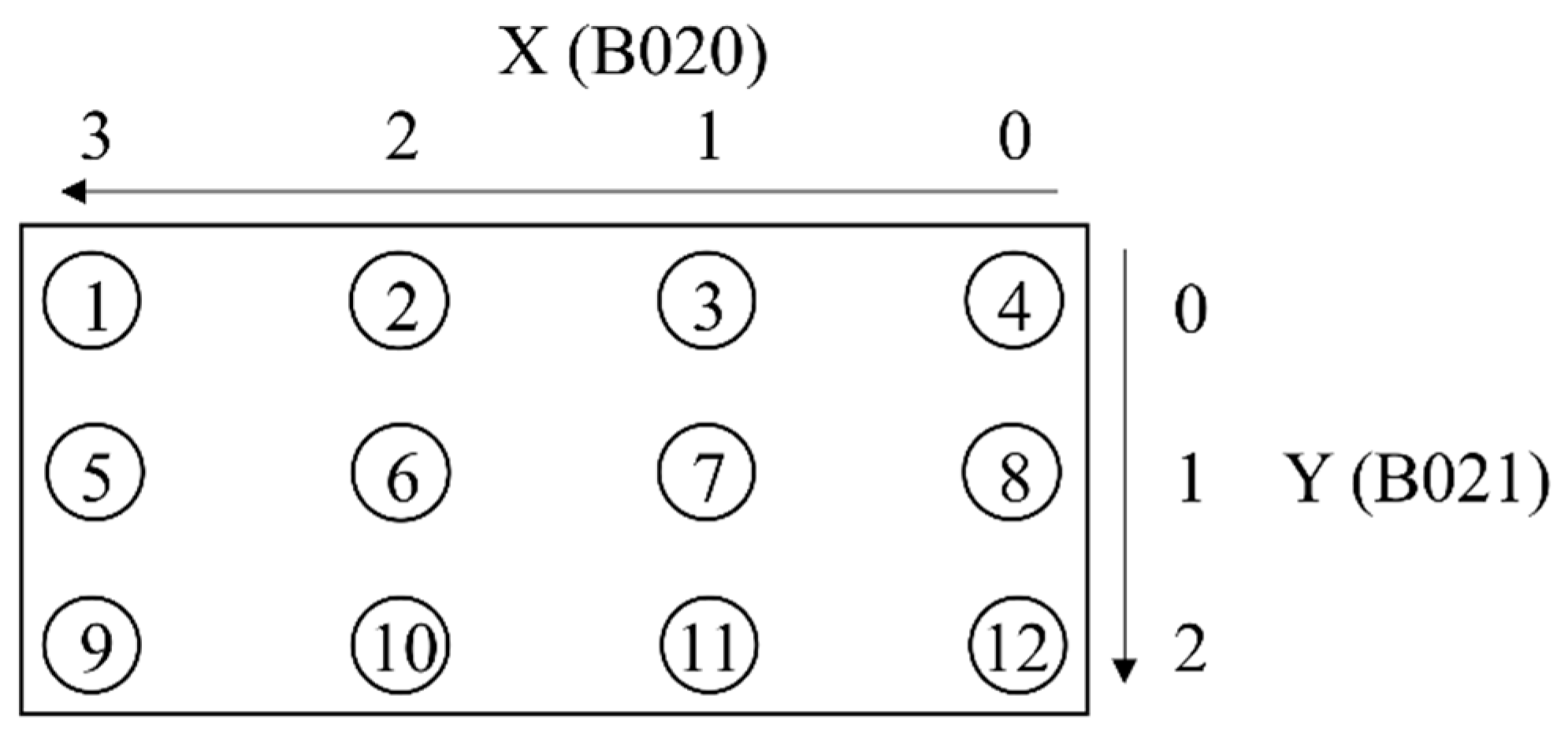
3Move pipette into vesselCalculationVessel type; Vessel position in Rack: X(B020), Y(B021); speed
4Move pipette out vesselCalculationVessel type; speed
5Tip eject to garbageTeach–in-
6Place pipetteTeach–in-
Table 5. Sequence control with robot jobs and pipetting commands (“XXX” = 200 or 1000 = pipette type).
No.TaskRobot JobPipetting Command
1Pick–up pipetteEP_XXX_PICKUPPipette initialization
2Load tipEP_XXX_LOADMove piston to home position
3Move to source labwareEP_XXX_INTO_VIAL
EP_XXX_OUT_VIAL
Liquid aspiration and/or liquid dispensing
4Move to destination labwareEP_XXX_INTO_VIAL
EP_XXX_OUT_VIAL
Liquid aspiration and/or liquid dispensing
5Positioning for tip ejectEP_XXX_TIPEJECTEject tip
6Positioning for safe starting positionEP_XXX_RELOAD-
7Place pipetteEP_XXX_PUTBACK-
Table 6. Format for XML messages between the process control software, SAMI, and the R–interface.
Byte12345678910111213 n
Message componentMessage length (first 4 bytes not included)DATA
Example000002FA< ?xml verommands>
Table 7. Measurement results of pipetting 100 µL using manual and electronic pipettes.
Manual PipetteElectronic Pipette
Number of pipettes 11
Expected volume [µL] 100100
Volume pipetted [µL] n = 12Average [µL]97.0795.42
STDEV [µL]1.403.62
CV [%]1.443.79
Table 8. Measurement results of pipetting 100 µL using manual and electronic pipettes.
Manual PipetteElectronic Pipette
Number of pipettes 31
Expected volume [µL] 100/200/10001000
Volume pipetted [µL] n = 12Average [µL]1276.501284.17
STDEV [µL]6.885.78
CV [%]0.540.45
Table 9. Process comparison for pipetting using manual and electronic pipettes.
Manual PipetteElectronic Pipette
Number of robotic arms involved21
Number of pipettes31
Number of tip boxes21
Number of pipetting steps to pipet a volume of 1300 µL3
(1000 µL + 200 µL + 100 µL)
2
(1000 µL + 300 µL)
Number of transportation steps
(pick–up/place back pipette and tip box)
104
Time for liquid aspiration4 s10 s
Time for liquid dispensing incl. droplet removal4 s15 s
Last droplet removed byPressing button to second pressure pointMoving piston at fast speed up and down
Time for single pipetting step
(aspiration + dispensing)
8 s25 s
Total process time incl. transportation12.2 min11.1 min

