Cracks Formation in Lithium-Rich Cathode Materials for Lithium-Ion Batteries during the Electrochemical Process
by
 ,
,
Tao Cheng
1,†, 
Zhongtao Ma
1,†,
Run Gu
1,
Riming Chen
1,
Yingchun Lyu
1,*,
Anmin Nie
1,2 and
Bingkun Guo
1,* 1
Materials Genome Institute, Shanghai University, Shanghai 200444, China
2
State Key Lab of Metastable Materials Science & Technology and Key Laboratory for Microstructure Material Physics of Hebei Province, Yanshan University, Qinhuangdao 066004, China
*
Authors to whom correspondence should be addressed.
†
These authors contributed equally to this work.
Energies 2018, 11(10), 2712; https://doi.org/10.3390/en11102712
Submission received: 21 September 2018
/
Revised: 5 October 2018
/
Accepted: 8 October 2018
/
Published: 11 October 2018
(This article belongs to the Special Issue Electrochemical Energy Conversion and Storage Technologies 2018)
Abstract
:The lithium-rich Li[Li0.2Ni0.13Mn0.54Co0.13]O2 nanoplates were synthesized using a molten-salt method. The nanoplates showed an initial reversible discharge capacity of 233 mA·h·g−1, with a fast capacity decay. The morphology and micro-structural change, after different cycles, were studied by a scanning electron microscope (SEM) and transmission electron microscopy (TEM) to understand the mechanism of the capacity decay. Our results showed that the cracks generated from both the particle surface and the inner, and increased with long-term cycling at 0.1 C rate (C = 250 mA·g−1), together with the layered to spinel and rock-salt phase transitions. These results show that the cracks and phase transitions could be responsible for the capacity decay. The results will help us to understand capacity decay mechanisms, and to guide our future work to improve the electrochemical performance of lithium-rich cathode materials.
1. Introduction
Since the introduction of rechargeable lithium-ion batteries to the consumer market in the early 1990s, material researchers have paid an increasing interest in efforts to improve the electrochemical performance of lithium-ion batteries [1,2,3,4,5]. The development of cathodes has greatly increased over the past decades, along with the need for high energy and power densities, long cycle life, and safety [6,7]. Traditional layered oxide [8,9], spinel compounds [10,11], and olivine compounds [12] are already successfully commercialized. However, the limited practical capacity of cathodes (<200 mA·h·g−1) restricts their further application for next generation batteries.
Recently, Li-rich layered oxide materials, composed of layered Li[Li1/3Mn2/3]O2 (generally denoted as Li2MnO3) and LiMO2 (M = Ni, Co, Mn, and other transition metal ions), have attracted much attention because of their high capacities (~250 mA·h·g−1) and high specific energies (≈900 Wh·kg−1) [13]. The Li2MnO3 component can stabilize the cathode structure and deliver large capacity at the initial charge plateau (4.4–4.6 V), wherein the lithium ions extract from the bulk structure concomitant with the release of oxygen (net loss of Li2O) [14,15,16]. Unfortunately, issues such as oxygen release, low initial Coulombic efficiency, poor rate performance, voltage fade, and capacity decay with cycling, restrict their commercial application [17,18,19,20,21]. Many research efforts, such as surface modification, atomic substitution, and optimization of synthesis strategies, have been pursued to improve the electrochemical performance of the Li-rich compounds. However, the problems remain unsolved in regards to the commercial application of these cathodes [13].
In order to understand the failure mechanism of the Li-rich cathode materials, various analytical techniques have been used, and it has been argued that the phase transitions are responsible for the failure [22,23,24,25]. Studies have shown that the removal of lithium ions from layer structure cathodes causes cation mixing between transition metal ions and lithium ions. This mixing results in the phase transformation from layered to spinel and rock–salt structure, and leads to the instability of the Li-rich materials structure [21,24,26,27,28]. Mohanty et al. have found the spinel phase occurred in the Li1.2Co0.1Mn0.55Ni0.15O2 sample after 16 cycles through in-situ X-ray diffraction (XRD) [29]. Zheng et al. have also observed the phase transformation from layered to spinel and rock–salt structure by aberration-corrected scanning transmission electron microscopy (STEM) [24]. Gu et al. have presented more detailed results by transmission electron microscopy (TEM). After hundreds of cycles, disoriented spinel domains are formed along with porosity and cracks in Li-rich particles [30,31]. Ito et al. also reported that micro cracks form in Li1.2Ni0.17Co0.07Mn0.56O2 after the initial charge/discharge to high potential over 4.5 V [32]. Xu et al. have found that structural integrity plays as a key factor in suppressing the voltage fade of Li-rich layered cathode materials through 3D X-ray imaging and spectroscopy techniques [21]. Through prelithiation of a model compound, Li2Ru0.5Mn0.5O3, Hu et al. further highlighted that the microstructural defect, including micro cracks, and oxygen release, form a positive feedback loop, and lead to the voltage fade and performance decay of Li-rich materials [25]. However, the prelithiation, and its related microstructural defect, are not commonly applied in battery working conditions. A more detailed and robust understanding of the crack phenomenon, and the phase evolution in the area around the cracks, will facilitate a better understanding of the failure mechanism of Li-rich materials and help researchers to find approaches that improve the electrochemical performance.
Synthesis strategies greatly affect the electrochemical behavior of electrode materials. Molten-salt method was applied to synthesize Li-rich crystals with high phase purity, and different morphologies can be achieved. Among which, the plate samples show an excellent electrochemical performance. The Li-rich Li[Li0.2Ni0.13Mn0.54Co0.13]O2 nanoplates were synthesized by a molten-salt method. An automated argon ion polishing system was used to section the pristine and long-term cycled cathodes. The crack formation and the micro-structure change around the crack were studied by a scanning electron microscope (SEM) and by transmission electron microscopy (TEM). The cracks were observed and the layered to spinel and rock–salt phase transitions were also found after long-term cycles.
2. Experimental Section
2.1. Materials Preparation
The Li[Li0.2Ni0.13Mn0.54Co0.13]O2 cathode was synthesized using a molten-salt method, which is commonly used to prepare transition-metal oxides with high pure phase [33]. All reagents (Alfa Aesar) were used as purchased. First, Mn(NO3)2·4H2O (27 mmol), Co(NO3)2·6H2O (6.5 mmol), Ni(NO3)2·6H2O (6.5 mmol), and LiNO3 (63 mmol, 5 mol % excess) were stoichiometrically mixed with KCl (transition metal ion: KCl = 1:2 in molar ratio) into 25 mL of ultrapure water. The solution was heated at 80 °C under agitation to remove the water. Following this, the mixture was transferred into an alumina crucible with a lid, heated to 850 °C at a rate of 3 °C min−1, and kept at a high temperature for 12 h. Finally, the Li[Li0.2Ni0.13Mn0.54Co0.13]O2 powder was obtained through washing with ultrapure water and then drying in a vacuum oven overnight at 80 °C.
2.2. Characterization
The structural analysis of the as-prepared powder was carried out using X-ray diffraction (XRD, Bruker D2) with a Cu Kα radiation source (λ1 = 1.54060 Å, λ2 = 1.54439 Å) over a 2θ range of 10 to 80° with a step size of 0.02°. The source voltage and current were 30 kV and 10 mA, respectively. The morphology and elements distribution of the samples was observed by field-emission scanning electron microscopy (FE-SEM, Regulus-8230, Hitachi, Tokyo, Japan) equipped with an energy dispersive spectrometer (EDS)-mapping (X-Max Extreme, Oxford-Instruments, Abingdon, UK). The pristine and cycled electrode samples for cross-section SEM observation were prepared by an automated argon ion polishing system (PECS II System model 685, Gatan, Pleasanton, CA, USA) with an ion-gun beam energy of 5 KeV. The high-resolution transmission electron microscopy (HR-TEM) measurements were performed by transmission electron microscopy (TEM, JEM-2100, JEOL, Tokyo, Japan).
2.3. Electrochemical Measurements
For the evaluation of electrochemical performance, the electrodes were fabricated with a mixture of as-prepared material powder (80%), acetylene carbon black (10%), polyvinylidene (PVDF) (10%) to generate a slurry, using N-methyl-2-pyrrolidone (NMP) as a solvent. The slurry was then coated onto an aluminum foil and dried in a vacuum oven overnight at 100 °C. Lithium foil and Celgard 2500 polypropylene membrane served as anode and separator, respectively. For the electrolyte, 1.2 M LiPF6 in ethylene carbonate (EC) and dimethyl carbonate (DEC) (1:1 in volume) was used. The cell components were assembled in the form of CR2032 coin cells in an argon-filled glovebox (Mbraun, UNIlab). The cells were cycled between 2.0 and 4.8 V vs. Li/Li+ at 0.1 C rate (C = 250 mA·g−1) in a constant current charging (CC) mode for electrochemical characterization. The charge and discharge data were gathered from the battery measurements system (CT2001, Lanhe) at room temperature.
3. Results and Discussion
The morphology of the as-prepared Li[Li0.2Ni0.13Mn0.54Co0.13]O2 particles were characterized by SEM. As shown in Figure 1a, most of the particles displayed a plate-like shape with an average diameter of between 400 to 800 nm. The chemical composition was confirmed by energy-dispersive X-ray (EDX) spectroscopy analysis, which indicated that the particles contained elements of Ni, Mn, and Co. The molar ratio of Ni, Mn, and Co was 0.14:0.53:0.13, which approximated to the designed ratio of 0.13:0.54:0.13.
X-ray diffraction was used to determine the material structure, and the collected pattern is shown in Figure 2a. The major diffraction peaks of the as-prepared sample were sharp, indicating high crystallinity. All the peaks can be indexed into the hexagonal α-NaFeO2 structure with space group Rm [34]. The splitting (006)/(012) and (018)/(110) peaks in the sample clearly indicate that the sample had a highly ordered hexagonal layered structure. The weak peaks, around the 2θ range of 20 to 25° belong to the superstructure reflections caused by the existence of the lithium ions and transition metal (TM) ions ordered in the TM layer [35]. The ratio of I(003)/I(104) could be used to measure the degree of the cation mixing among layered lithium metal oxide. The value of I(003)/I(104) in the as-prepared sample was 1.8, higher than 1.2, indicating that the as-prepared sample had a low degree of the undesirable cation mixing [36]. Furthermore, Figure 2b shows the TEM image of the sample. Figure 2b shows that the particle presented a plate shape, and no fragmentation can be observed, as suggested by the SEM results. All the results indicated that pure phase Li-rich layered cathode material with plate shape was obtained by the molten-salt method.
Figure 3 shows the typical charge and discharge profile of the Li[Li0.2Ni0.13Mn0.54Co0.13]O2 cathode for selected cycles. The cells were tested between 2.0 and 4.8 V vs. Li/Li+ at 0.1 C rate at room temperature. The curves are in accord with those previously reported on other Li-rich cathode materials. The initial charge curve shows a slope below 4.4 V ascribed to the transition metal redox, and a long plateau region at ~4.5 V belongs to further extraction of lithium ions from the Li2MnO3 component and the anion (O2−) oxidation, which is consistent with others’ results [37]. The ~4.5 V plateau was not seen during the first discharge and the second charge. The initial charge and discharge capacities were 313.1 and 233.4 mA·h·g−1, with an initial coulombic efficiency of 74.56%. The low initial coulombic efficiency may be ascribed to the large size particles. [38,39,40]. Dahn et al. have showed that both particle size and synthesis method may influence the electrochemical performance of electrode materials [41]. As shown in Figure 3, the average voltage of the discharge curve decreased continuously during the cycle, which is the so-called voltage fade phenomenon for Li-rich cathodes. The discharge capacity also decreased during the cycle. It retained 79.43% of its initial capacity after 50 cycles, but the capacity underwent a sudden drop and the coulombic efficiency became volatile after that. After 100 cycles, the capacity retention ratio was only 17.2%.
To understand the mechanism of voltage fade and capacity decay of the Li-rich materials on the particle plane, the cross-sectional morphology of the electrodes after different cycles were detected by SEM. As shown in Figure 4a, all particles in the pristine sample were intact and no crack can be seen. After 10 cycles (Figure 4b), cracks were found in several particles. With the increasing cycles, the cracks increased in both number and size (Figure 4c,d after 60 and 100 cycles), some particles even became pulverized, leading to the formation of fragments. The cracks not only formed at the particle surface, but also the particle inner. Similar results have been reported by Yan et al. during their research on LiNi1/3Mn1/3Co1/3O2. Their results suggest that this was a consequence of a dislocation-based crack incubation mechanism [42]. The cracks and the associated phase change are considered to be the main reason for the failure of LiNi1/3Mn1/3Co1/3O2 and LiNiO2 at high-voltage usage [42,43]. The crack may result from the non-uniform volume change and the generated stress upon lithium ion extraction and reinsertion. During the charge process of layered oxides, Li ions were extracted from the lattice, which caused lattice expansion along the c direction, and shrinkage along the a and b directions, and the reverse process was seen during discharge. In-situ XRD on Li1.2Co0.1Mn0.55Ni0.15O2 indicated that, during the first cycle, the layered materials underwent an anisotropic structure change. In the first charge process, the c-lattice parameter expanded from 14.27 Å to about 14.43 Å, while the a-lattice shrank from 2.85 Å to about 2.83 Å [29]. The expansion and shrinkage of lattice parameters induced significant strain on the Li-rich layered materials.
The cycled samples were observed to investigate the crystal structure change around the cracks. The TEM images for the particles after 10 cycles are shown in Figure 5. Figure 5a,b demonstrate that a crack was generated from the particle surface to the bulk. Figure 5c exhibits the selected area electron diffraction (SAED) pattern of cycled particle bulk according with the layered Rm diffraction spots with the () axis, which indicated that the particle mainly kept the layered structure. As shown in Figure 5d, a spinel phase generated in the crack near the particle surface was observed. The lattice fringes from the HR-TEM and spots from the FFT pattern indicated interplanar distances of 0.47, 0.28, and 0.41 nm, belonging to the (11), (2), and () planes of LiMn2O4—type spinel phase. These results indicate that the bulk structure maintained the layered phase and the crack was generated with the phase transformation from layered to spinel in the crack vicinity. Along with crack formation and growth upon cycling, the particle surface underwent a layered to spinel phase transformation, accompanied by the release of oxygen from the structure.
After 100 cycles, the cracks increased to a larger size scale. The cracks led to the generation of new sites for surface phase transformation, corrosion, and side reactions, consequently accelerating cell degradation. HR-TEM image of region I is shown in Figure 6d. It clearly exhibits lattice fringes with an interplanar distance of between 0.21 and 0.245 nm, belonging to the () and () planes of rock–salt phase, respectively. The fast Fourier transform (FFT) result showed a representative pattern of a rock–salt structure with the () axis, which is different from the results obtained from particles after 10 cycles (Figure 5d), where the spinel reflections were observed. These results confirm that the spinel phase transforms to a rock–salt phase in the vicinity of cracks [44], which has been suggested as one of the main origins for the voltage fade of Li-rich cathode materials during long-term cycling.
4. Conclusions
Li[Li0.2Ni0.13Mn0.54Co0.13]O2 nanoplates were synthesized through a molten-salt method. As a cathode material for lithium-ion batteries, it showed an initial discharge capacity of 233 mA·h·g−1 and suffered from capacity fading with a capacity loss of 20% after 50 cycles and 83% after 100 cycle, respectively. The cracks, along with phase transitions from layered to spinel and rock-salt phase, were observed after long-term cycling, which could be responsible for the capacity decay.
Author Contributions
Y.L. and B.G. conceived and designed the experiments; T.C. and Z.M. performed the experiments and analyzed the experiment data with the help of R.G., R.C. and A.N.; T.C., Y.L., and B.G. wrote the paper.
Funding
This work was supported by the National Key R&D Program of China (Grant No. 2018YFB0104300), the National Science Foundation of China (Grant Nos. 51602191, 51602190, 11702165), the Program for Professor of Special Appointment (Eastern Scholar) at Shanghai Institutions of Higher Learning, Science and Technology Commission of Shanghai Municipality (Grant No.18010500300), and 111 project (D16002).
Conflicts of Interest
The authors declare no conflict of interest.
Nomenclatures
| Li-rich | lithium-rich |
| SEM | scanning electron microscope |
| TEM | transmission electron microscopy |
| mA·g−1 | milliampere per gram |
| mA·h·g−1 | milliampere hour per gram |
| V | voltage |
| XRD | X-ray diffraction |
| STEM | scanning transmission electron microscopy |
| 3D | three dimensional |
| mmol | milimolar |
| FE-SEM | field-emission scanning electron microscopy |
| EDS | energy dispersive spectrometer |
| HR-TEM | high-resolution transmission electron microscopy |
| PVDF | polyvinylidene |
| NMP | N-methyl-2-pyrrolidone |
| M | molar per liter |
| EC | ethylene carbonate |
| DEC | dimethyl carbonate |
| C-rate | a measure of the rate at which a battery is charged or discharged relative to its capacity |
| CC | constant current |
| Li+ | lithium ion |
| EDX | energy-dispersive X-ray |
| 2θ | measuring the angle of scattering angle in XRD |
| TM | transition metal |
| Rm | of a kind of space group, group number 166 |
| I(003) | the intensity of (003) peak in XRD pattern |
| SAED | selected area electron diffraction |
| FFT | fast Fourier transform |
References
- Armand, M.; Tarascon, J.M. Building better batteries. Nature 2008, 451, 652–657. [Google Scholar] [CrossRef] [PubMed]
- Bruce, P.G.; Scrosati, B.; Tarascon, J.M. Nanomaterials for rechargeable lithium batteries. Angew. Chem. Int. Ed. Engl. 2008, 47, 2930–2946. [Google Scholar] [CrossRef] [PubMed]
- Whittingham, M.S. Ultimate Limits to Intercalation Reactions for Lithium Batteries. Chem. Rev. 2014, 114, 11414–11443. [Google Scholar] [CrossRef] [PubMed]
- Chiang, Y.-M. Building a Better Battery. Science 2010, 330, 1485–1486. [Google Scholar] [CrossRef] [PubMed]
- Koksbang, R.; Barker, J.; Shi, H.; Saidi, M.Y. Cathode materials for lithium rocking chair batteries. Solid State Ion. 1996, 84, 1–21. [Google Scholar] [CrossRef]
- Goodenough, J.B.; Kim, Y. Challenges for Rechargeable Li Batteries. Chem. Mater. 2010, 22, 587–603. [Google Scholar] [CrossRef]
- Li, W.; Song, B.; Manthiram, A. High-voltage positive electrode materials for lithium-ion batteries. Chem. Soc. Rev. 2017, 46, 3006–3059. [Google Scholar] [CrossRef] [PubMed]
- Manthiram, A.; Song, B.; Li, W. A perspective on nickel-rich layered oxide cathodes for lithium-ion batteries. Energy Storage Mater. 2017, 6, 125–139. [Google Scholar] [CrossRef]
- Kalluri, S.; Yoon, M.; Jo, M.; Park, S.; Myeong, S.; Kim, J.; Dou, S.X.; Guo, Z.; Cho, J. Surface Engineering Strategies of Layered LiCoO2 Cathode Material to Realize High-Energy and High-Voltage Li-Ion Cells. Adv. Energy Mater. 2017, 7. [Google Scholar] [CrossRef]
- Tang, D.; Sun, Y.; Yang, Z.; Ben, L.; Gu, L.; Huang, X. Surface structure evolution of LiMn2O4 cathode material upon charge/discharge. Chem. Mater. 2014, 26, 3535–3543. [Google Scholar] [CrossRef]
- Ma, J.; Hu, P.; Cui, G.; Chen, L. Surface and Interface Issues in Spinel LiNi0.5Mn1.5O4: Insights into a Potential Cathode Material for High Energy Density Lithium Ion Batteries. Chem. Mater. 2016, 28, 3578–3606. [Google Scholar] [CrossRef]
- Padhi, A.K.; Nanjundaswamy, K.S.; Goodenough, J.B. Phospho-olivines as positive-electrode materials for rechargeable lithium batteries. J. Electrochem. Soc. 1997, 144, 1188–1194. [Google Scholar] [CrossRef]
- Zheng, J.; Myeong, S.; Cho, W.; Yan, P.; Xiao, J.; Wang, C.; Cho, J.; Zhang, J.-G. Li- and Mn-Rich Cathode Materials: Challenges to Commercialization. Adv. Energy Mater. 2017, 7, 1601284. [Google Scholar] [CrossRef]
- Thackeray, M.M.; Kang, S.-H.; Johnson, C.S.; Vaughey, J.T.; Benedek, R.; Hackney, S.A. Li2MnO3-stabilized LiMO2 (M = Mn, Ni, Co) electrodes for lithium-ion batteries. J. Mater. Chem. 2007, 17, 3112–3125. [Google Scholar] [CrossRef]
- Koga, H.; Croguennec, L.; Menetrier, M.; Douhil, K.; Belin, S.; Bourgeois, L.; Suard, E.; Weill, F.; Delmas, C. Reversible Oxygen Participation to the Redox Processes Revealed for Li1.20Mn0.54Co0.13Ni0.13O2. J. Electrochem. Soc. 2013, 160, A786–A792. [Google Scholar] [CrossRef]
- Hong, J.; Lim, H.-D.; Lee, M.; Kim, S.-W.; Kim, H.; Oh, S.-T.; Chung, G.-C.; Kang, K. Critical Role of Oxygen Evolved from Layered Li-Excess Metal Oxides in Lithium Rechargeable Batteries. Chem. Mater. 2012, 24, 2692–2697. [Google Scholar] [CrossRef]
- Yan, J.; Liu, X.; Li, B. Recent progress in Li-rich layered oxides as cathode materials for Li-ion batteries. RSC Adv. 2014, 4, 63268–63284. [Google Scholar] [CrossRef]
- Yu, H.; Zhou, H. Initial Coulombic efficiency improvement of the Li1.2Mn0.567Ni0.166Co0.067O2 lithium-rich material by ruthenium substitution for manganese. J. Mater. Chem. 2012, 22, 15507–15510. [Google Scholar] [CrossRef]
- Zang, Y.; Ding, C.-X.; Wang, X.-C.; Wen, Z.-Y.; Chen, C.-H. Molybdenum-doped lithium-rich layered-structured cathode material Li1.2Ni0.2Mn0.6O2 with high specific capacity and improved rate performance. Electrochim. Acta 2015, 168, 234–239. [Google Scholar] [CrossRef]
- Zang, Y.; Sun, X.; Tang, Z.-F.; Xiang, H.-F.; Chen, C.-H. Vanadium-doped lithium-rich layered-structured cathode material Li1.2Ni0.2Mn0.6O2 with a high specific capacity and improved rate performance. RSC Adv. 2016, 6, 30194–30198. [Google Scholar] [CrossRef]
- Xu, Y.; Hu, E.; Yang, F.; Corbett, J.; Sun, Z.; Lyu, Y.; Yu, X.; Liu, Y.; Yang, X.-Q.; Li, H. Structural integrity-Searching the key factor to suppress the voltage fade of Li-rich layered cathode materials through 3D X-ray imaging and spectroscopy techniques. Nano Energy 2016, 28, 164–171. [Google Scholar] [CrossRef]
- Lyu, Y.; Hu, E.; Xiao, D.; Wang, Y.; Yu, X.; Xu, G.; Ehrlich, S.N.; Amine, K.; Gu, L.; Yang, X.-Q.; et al. Correlations between Transition-Metal Chemistry, Local Structure, and Global Structure in Li2Ru0.5Mn0.5O3 Investigated in a Wide Voltage Window. Chem. Mater. 2017, 29, 9053–9065. [Google Scholar] [CrossRef]
- Su, N.; Lyu, Y.; Gu, R.; Guo, B. Al2O3 coated Li1.2Ni0.2Mn0.2Ru0.4O2 as cathode material for Li-ion batteries. J. Alloys Compd. 2018, 741, 398–403. [Google Scholar] [CrossRef]
- Zheng, J.; Xu, P.; Gu, M.; Xiao, J.; Browning, N.D.; Yan, P.; Wang, C.; Zhang, J.-G. Structural and Chemical Evolution of Li- and Mn-Rich Layered Cathode Material. Chem. Mater. 2015, 27, 1381–1390. [Google Scholar] [CrossRef]
- Hu, E.; Lyu, Y.; Xin, H.L.; Liu, J.; Han, L.; Bak, S.-M.; Bai, J.; Yu, X.; Li, H.; Yang, X.-Q. Explore the Effects of Microstructural Defects on Voltage Fade of Li- and Mn-Rich Cathodes. Nano Lett. 2016, 16, 5999–6007. [Google Scholar] [CrossRef] [PubMed]
- Shukla, A.K.; Ramasse, Q.M.; Ophus, C.; Duncan, H.; Hage, F.; Chen, G. Unravelling structural ambiguities in lithium- and manganese-rich transition metal oxides. Nat. Commun. 2015, 6, 8711. [Google Scholar] [CrossRef] [PubMed] [Green Version]
- Song, B.; Liu, Z.; Lai, M.O.; Lu, L. Structural evolution and the capacity fade mechanism upon long-term cycling in Li-rich cathode material. Phys. Chem. Chem. Phys. 2012, 14, 12875–12883. [Google Scholar] [CrossRef] [PubMed]
- Yan, P.; Nie, A.; Zheng, J.; Zhou, Y.; Lu, D.; Zhang, X.; Xu, R.; Belharouak, I.; Zu, X.; Xiao, J.; et al. Evolution of lattice structure and chemical composition of the surface reconstruction layer in Li1.2Ni0.2Mn0.6O2 cathode material for lithium ion batteries. Nano Lett. 2015, 15, 514–522. [Google Scholar] [CrossRef] [PubMed]
- Mohanty, D.; Kalnaus, S.; Meisner, R.A.; Rhodes, K.J.; Li, J.; Payzant, E.A.; Wood, D.L., III; Daniel, C. Structural transformation of a lithium-rich Li1.2Co0.1Mn0.55Ni0.15O2 cathode during high voltage cycling resolved by in situ X-ray diffraction. J. Sources 2013, 229, 239–248. [Google Scholar] [CrossRef]
- Gu, M.; Belharouak, I.; Zheng, J.; Wu, H.; Xiao, J.; Genc, A.; Amine, K.; Thevuthasan, S.; Baer, D.R.; Zhang, J.-G.; et al. Formation of the Spinel Phase in the Layered Composite Cathode Used in Li-Ion Batteries. ACS Nano 2013, 7, 760–767. [Google Scholar] [CrossRef] [PubMed]
- Zheng, J.; Gu, M.; Xiao, J.; Zuo, P.; Wang, C.; Zhang, J.-G. Corrosion/Fragmentation of Layered Composite Cathode and Related Capacity/Voltage Fading during Cycling Process. Nano Lett. 2013, 13, 3824–3830. [Google Scholar] [CrossRef] [PubMed]
- Ito, A.; Li, D.; Sato, Y.; Arao, M.; Watanabe, M.; Hatano, M.; Horie, H.; Ohsawa, Y. Cyclic deterioration and its improvement for Li-rich layered cathode material Li[Ni0.17Li0.2Co0.07Mn0.56]O2. J. Power Sources 2010, 195, 567–573. [Google Scholar] [CrossRef]
- Kim, J.H.; Myung, S.T.; Sun, Y.K. Molten salt synthesis of LiNi0.5Mn1.5O4 spinel for 5 V class cathode material of Li-ion secondary battery. Electrochim. Acta 2004, 49, 219–227. [Google Scholar] [CrossRef]
- Wu, F.; Zhang, X.; Zhao, T.; Li, L.; Xie, M.; Chen, R. Multifunctional AlPO4 Coating for Improving Electrochemical Properties of Low-Cost Li[Li0.2Fe0.1Ni0.15Mn0.55]O2 Cathode Materials for Lithium-Ion Batteries. ACS Appl. Mater. Interfaces 2015, 7, 3773–3781. [Google Scholar] [CrossRef] [PubMed]
- Wu, Y.; Manthiram, A. Structural stability of chemically delithiated layered (1-z)Li[Li1/3Mn2/3] O2-zLi[Mn0.5−yNi0.5−yCo2y]O2 solid solution cathodes. J. Power Sources 2008, 183, 749–754. [Google Scholar] [CrossRef]
- Liu, J.; Reeja-Jayan, B.; Manthiram, A. Conductive Surface Modification with Aluminum of High Capacity Layered Li[Li0.2Mn0.54Ni0.13Co0.13]O2 Cathodes. J. Phys. Chem. C 2010, 114, 9528–9533. [Google Scholar] [CrossRef]
- Wang, C.-C.; Jarvis, K.A.; Ferreira, P.J.; Manthiram, A. Effect of Synthesis Conditions on the First Charge and Reversible Capacities of Lithium-Rich Layered Oxide Cathodes. Chem. Mater. 2013, 25, 3267–3275. [Google Scholar] [CrossRef]
- Kim, Y. Lithium Nickel Cobalt Manganese Oxide Synthesized Using Alkali Chloride Flux: Morphology and Performance as a Cathode Material for Lithium Ion Batteries. ACS Appl. Mater. Interfaces 2012, 4, 2329–2333. [Google Scholar] [CrossRef] [PubMed]
- Zuo, Y.; Ma, J.; Jiang, N.; Xia, D. Effects of Particle Size on Voltage Fade for Li-Rich Mn-Based Layered Oxides. ACS Omega 2018, 3, 11136–11143. [Google Scholar] [CrossRef]
- Kuppan, S.; Shukla, A.K.; Membreno, D.; Nordlund, D.; Chen, G. Revealing Anisotropic Spinel Formation on Pristine Li- and Mn-Rich Layered Oxide Surface and Its Impact on Cathode Performance. Adv. Energy Mater. 2017, 7, 1602010. [Google Scholar] [CrossRef]
- Li, J.; Shunmugasundaram, R.; Doig, R.; Dahn, J.R. In Situ X-ray Diffraction Study of Layered Li-Ni-Mn-Co Oxides: Effect of Particle Size and Structural Stability of Core-Shell Materials. Chem. Mater. 2016, 28, 162–171. [Google Scholar] [CrossRef]
- Yan, P.; Zheng, J.; Gu, M.; Xiao, J.; Zhang, J.-G.; Wang, C.-M. Intragranular cracking as a critical barrier for high-voltage usage of layer-structured cathode for lithium-ion batteries. Nat. Commun. 2017, 8. [Google Scholar] [CrossRef] [PubMed]
- Yoon, C.S.; Jun, D.-W.; Myung, S.-T.; Sun, Y.-K. Structural Stability of LiNiO2 Cycled above 4.2 V. ACS Energy Lett. 2017, 2, 1150–1155. [Google Scholar] [CrossRef]
- Yoon, C.S.; Ryu, H.-H.; Park, G.-T.; Kim, J.-H.; Kim, K.-H.; Sun, Y.-K. Extracting maximum capacity from Ni-rich Li[Ni0.95Co0.025Mn0.025]O2 cathodes for high-energy-density lithium-ion batteries. J. Mater. Chem. A 2018, 6, 4126–4132. [Google Scholar] [CrossRef]
Figure 1.
(a) SEM images and (b) energy-dispersive X-ray (EDX) spectrum of the Li[Li0.2Ni0.13Mn0.54Co0.13]O2 particles.
Figure 1.
(a) SEM images and (b) energy-dispersive X-ray (EDX) spectrum of the Li[Li0.2Ni0.13Mn0.54Co0.13]O2 particles.

Figure 2.
(a) X-ray diffraction (XRD) pattern and (b) transmission electron microscopy (TEM) image of the Li[Li0.2Ni0.13Mn0.54Co0.13]O2.
Figure 2.
(a) X-ray diffraction (XRD) pattern and (b) transmission electron microscopy (TEM) image of the Li[Li0.2Ni0.13Mn0.54Co0.13]O2.

Figure 3.
(a) The charge/discharge curve of Li[Li0.2Ni0.13Mn0.54Co0.13]O2 for different cycles. (b) The cycling performance of Li[Li0.2Ni0.13Mn0.54Co0.13]O2.
Figure 3.
(a) The charge/discharge curve of Li[Li0.2Ni0.13Mn0.54Co0.13]O2 for different cycles. (b) The cycling performance of Li[Li0.2Ni0.13Mn0.54Co0.13]O2.
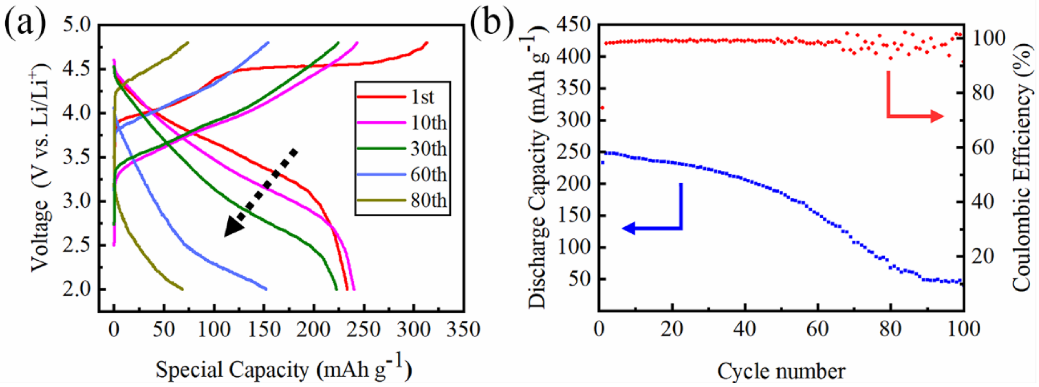
Figure 4.
Cross-sectional SEM images of the polished electrode samples: (a) Pristine electrode; (b) after 10 cycles; (c) after 60 cycles, and (d) after 100 cycles. The cracks and fragments are marked by red arrows and rings.
Figure 4.
Cross-sectional SEM images of the polished electrode samples: (a) Pristine electrode; (b) after 10 cycles; (c) after 60 cycles, and (d) after 100 cycles. The cracks and fragments are marked by red arrows and rings.

Figure 5.
(a) The TEM image of Li[Li0.2Ni0.13Mn0.54Co0.13]O2 after 10 cycles between 2 and 4.8 V at 0.1 C rate. (b) The higher magnification image of the red square area of panel (a). (c) Selected area electron diffraction (SAED) pattern of the particle bulk in panel (a). (d) The HR-TEM image and fast Fourier transform (FFT) pattern (inset) of the orange square area of panel (b).
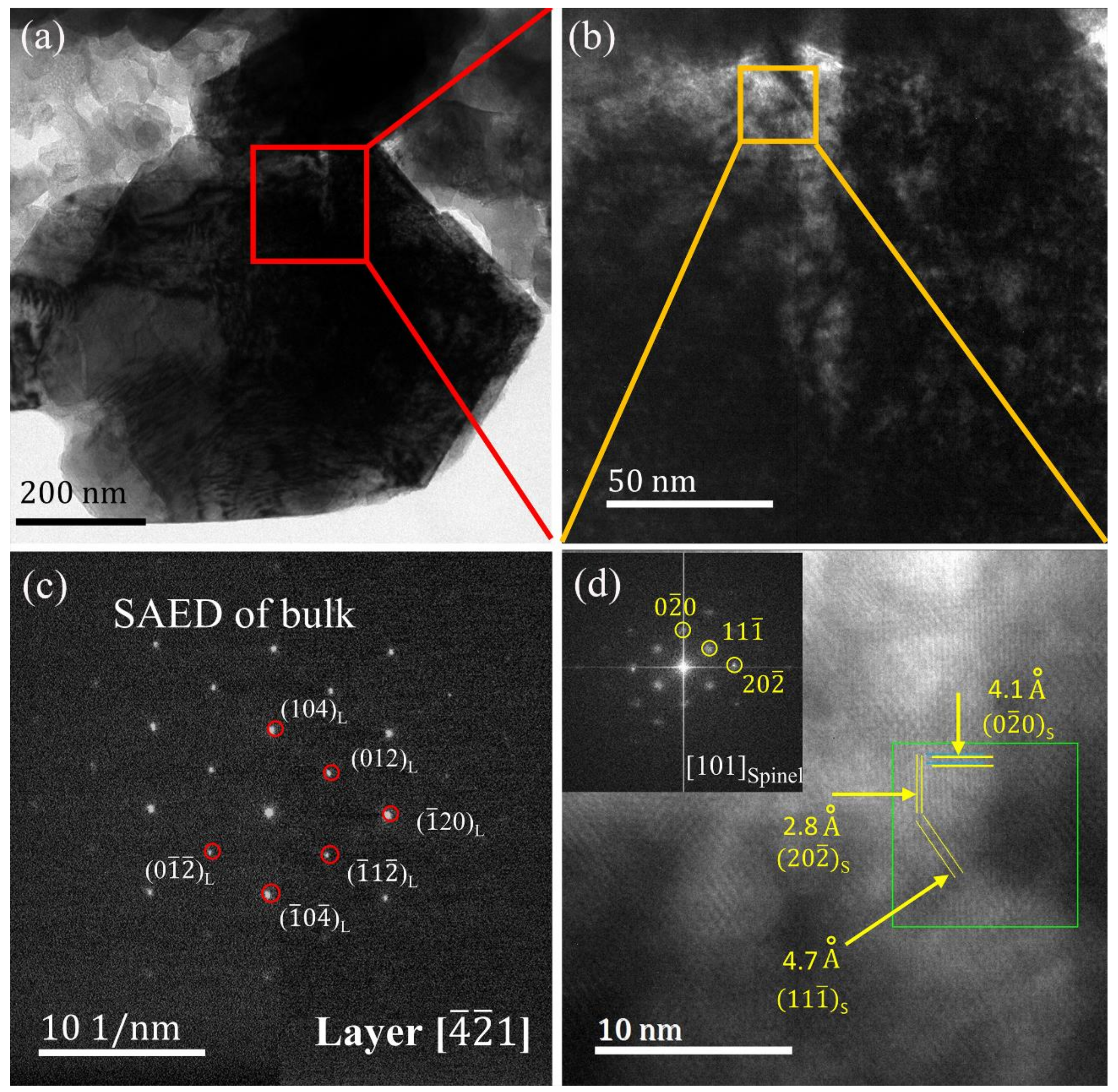
Figure 6.
(a) The TEM imagine of Li[Li0.2Ni0.13Mn0.54Co0.13]O2 after 100 cycles between 2 and 4.8 V at 0.1 C rate. (b,c) the higher magnification image of the crack in panel. (d) The HR-TEM image and FFT pattern (inset) of region I stressed by a red circle in panel.
Figure 6.
(a) The TEM imagine of Li[Li0.2Ni0.13Mn0.54Co0.13]O2 after 100 cycles between 2 and 4.8 V at 0.1 C rate. (b,c) the higher magnification image of the crack in panel. (d) The HR-TEM image and FFT pattern (inset) of region I stressed by a red circle in panel.

© 2018 by the authors. Licensee MDPI, Basel, Switzerland. This article is an open access article distributed under the terms and conditions of the Creative Commons Attribution (CC BY) license (http://creativecommons.org/licenses/by/4.0/).
Share and Cite
MDPI and ACS Style
Cheng, T.; Ma, Z.; Gu, R.; Chen, R.; Lyu, Y.; Nie, A.; Guo, B. Cracks Formation in Lithium-Rich Cathode Materials for Lithium-Ion Batteries during the Electrochemical Process. Energies 2018, 11, 2712. https://doi.org/10.3390/en11102712
AMA Style
Cheng T, Ma Z, Gu R, Chen R, Lyu Y, Nie A, Guo B. Cracks Formation in Lithium-Rich Cathode Materials for Lithium-Ion Batteries during the Electrochemical Process. Energies. 2018; 11(10):2712. https://doi.org/10.3390/en11102712
Chicago/Turabian StyleCheng, Tao, Zhongtao Ma, Run Gu, Riming Chen, Yingchun Lyu, Anmin Nie, and Bingkun Guo. 2018. "Cracks Formation in Lithium-Rich Cathode Materials for Lithium-Ion Batteries during the Electrochemical Process" Energies 11, no. 10: 2712. https://doi.org/10.3390/en11102712
Note that from the first issue of 2016, this journal uses article numbers instead of page numbers. See further details here.