Article

Automatic Generation Control of Nuclear Heating Reactor Power Plants

Institute of Nuclear and New Energy Technology, Collaborative Innovation Centre of Advanced Nuclear Energy Technology, Key Laboratory of Advanced Reactor Engineering and Safety of Ministry of Education, Tsinghua University, Beijing 100084, China
*
Author to whom correspondence should be addressed.
Energies 2018, 11(10), 2782; https://doi.org/10.3390/en11102782
Submission received: 12 September 2018 / Revised: 3 October 2018 / Accepted: 12 October 2018 / Published: 16 October 2018
(This article belongs to the Special Issue Nuclear Power, Including Fission and Fusion Technologies)

Abstract

:
A nuclear heating reactor (NHR) is a typical integral pressurized water reactor (iPWR) with advanced design features such as an integral primary circuit, self-pressurization, full-power-range natural circulation, and hydraulic control rods. Through adjusting its electric power output according to the variation of demand, NHR power plants can be adopted to stablize the fluctuation of grid frequency caused by the intermittent nature of renewable generation, which is useful for deepening the penetration of renewables. The flexibility of an NHR power plant relies on the automatic generation control (AGC) function of the plant coordination control system, whose central is the AGC law. In this paper, the plant control system with AGC function is designed for NHR plants, where the AGC is realized based on the stabilizers of grid frequency and main steam pressure. Then, the AGC problem is transferred to the disturbance attenuation problem of a second-order dynamic system, and an active disturbance attenuation control (ADRC), which is just the addition of a feedback control given by a proportional‒integral (PI) law and a feedforward control driven by a disturbance observer (DO), is then proposed. Finally, this ADRC is applied to realize the AGC function for NHR-200II reactor power plant, and numerical simulation results show the implementation feasibility and satisfactory performance.

1. Introduction

Due to their zero marginal cost of electricity production, renewable energy sources such as wind and solar are regarded as important contributors to the world electric power provision. However, renewable generation not only heavily depends on climatic conditions but also requires a very large land footprint. With comparison to renewables, nuclear power plants (NPPs) can provide consistent electricity while requiring much less land [1]. Moreover, to balance the power supply and demand in the context of deep renewable penetration, it is necessary to provide enough backup flexibility, which can be provided on a large scale by burning fossil fuels or nuclear fission reactions. Since nuclear fission and renewables are both clean energy resources, it is meaningful to interconnect them for building carbon-free energy systems, i.e., nuclear hybrid energy systems (NHESs). One of the key techniques in developing NHESs is the flexibility of NPPs, which refers to the capability of adjusting the plant electric power output according to demand, and can further deepen the penetration of renewables through reducing their curtailment. It has been shown that the flexibility of NPPs is realizable if the limitations in axial power offset, fuel integrity, fission product poisoning, and temperature variation are all well satisfied [2], and is a crucial factor in maximizing the profit of producers [3,4]. A case study based on utility data from the Southwest USA in [5] shows that the flexibility of NPPs can not only increase the revenue of NPP owners but also lower the operational cost of the grid. It is even pointed out through analysis in [6] that adopting small modular nuclear reactors (SMRs) to balance the renewables is the only existing technology that can provide reliable, carbon-free electricity in a scalable manner. Small modular reactors (SMRs) are defined as those fission reactors whose electrical power is less than 300 MWe, and have already been seen as an important trend in the nuclear energy industry [7,8,9,10]. SMRs with integral primary circuits and light-water as primary coolant are called integral pressurized water reactors (iPWRs). The IRIS, NuScale, and mPower designed by the USA and the SMART designed by Korea are all typical iPWR designs with advanced features such as natural circulation, self-pressurization, hydraulic control rod, and passive decay heat removal, which prevents the reactors from hazards such as core-melting, radiological release, and LOCA (Loss of Coolant Accident). Moreover, iPWRs can offer simpler, safer, and standardized modular design by being factory built, requiring smaller initial capital investment and having a shorter construction period [7,8]. Due to their improved nuclear safety level, iPWRs are more feasible than large-scale PWRs.
A nuclear heating reactor (NHR) is a typical iPWR with inherent safety features such as integral primary circuit, full-power-range natural circulation, self-pressurization, and built-in hydraulic control rods [11,12,13,14,15,16,17,18]. Due to these features, no off-site emergency actions such as evacuation, sheltering, and decontamination are required in the case of all credible accidents. The study of NHR technology started in China in the early 1980s, and the first NHR, i.e., the 5 MWth test reactor *NHR-5), began to be built at the Institute of Nuclear and New Energy Technology (INET) of Tsinghua University in March 1986, and has operated at full power since December 1989 [11,12,13]. Based on NHR-5, the design of a 200 MWth nuclear heating reactor (NHR-200) was accomplished in the middle of the 1990s; it is used for electricity generation, district heating, and seawater desalination [14,15,16,17]. On the basis of the NHR-200 design, and by improving the pressure of the primary coolant and live steam for higher efficiency, a nuclear heating reactor NHR200-II with a rated thermal power of 200 MWth was developed by INET very recently [18]. Although the power rating of NHR-200II is relatively low, due to its inherent safety features it can be adopted to balance renewables by adjusting its electric power output, which relies on the automatic generation control (AGC) of the NHR-200II plant.
The past and current study of the control of nuclear plants mainly focuses on the power-level control of nuclear reactors, and a series of advanced control methods have been developed such as sliding mode control (SMC), model predictive control (MPC), and physics-based control (PBC) approaches [19]. However, there are still very limited results on AGC of nuclear plants. In this paper, a control system scheme with AGC function is first designed for the NHR-200II power plant. Then, the problems stabilizing the main steam pressure and grid frequency are transferred to the disturbance attenuation problem of a second-order dynamical system, and an active disrurbance rejection control (ADRC) is proposed, composed of a proportional‒integral feedback term and a feedforward term given by a disturbance observer (DO). Finally, this ADRC is applied to realize the AGC function for a NHR-200II power plant, and numerical simulation results in the cases of power stepping and maneuvering show the feasibility and satisfactory performance.

2. General Description of NHR-200II Power Plant

The structure of NHR-200II is illustrated in Figure 1, from which it can be seen that the reactor system and primary circuit (PC), including the riser, downcomer, and 14 primary heat exchangers (PHEs), are arranged into the reactor pressure vessel (RPV). The core is located at the bottom of RPV, which is composed of fuel assemblies with fuel boxes and cruciform control rods. The PHEs are arranged in the annular space between the riser and RPV. The natural circulation of PC, which can sufficiently cool down the reactor core in the full power range, is driven by the density difference between the coolant inside the core and PHEs, and is hydraulically enhanced by the riser. Futhermore, the schematic diagram of the NHR-200II power plant is shown in Figure 2.
The heat generated by a nuclear fission reaction is transferred from the primary circuit (PC) to the two intermediate circuits (ICs) via the PHEs, and is successivefully transferred to the secondary side of UTSGs so as to turn the supercooled feedwater into saturated steam. Then the main steam flow formed by the combination of the live steam flows from two UTSGs is guided to the high-pressure (HP) cylinder of the turbine so as to drive the turbine/generator set for producing electrical power. A comparison of the main design parameters of the NHR-200II plant and those of the NHR-200 plant is given in Table 1. It can be seen from Table 1 that the ICs operate at a pressure that is a little higher than the pressure of PC, which can effectively suppress the leakage of radioactive fission products.

3. Plant Control Scheme with AGC Function

To achieve flexible operation of NHR and deepen the penetration of IRE, it is necessary to realize automatic generation control. The designed hierarchy control scheme of NHR power plants with automatic generation function is shown in Figure 3, from which it can be seen that the entire closed loop is divided into the levels of process, equipment, system controlm and coordination. The process level is composed of the physical and thermal‒hydraulic processes including the NHR, ICs, UTSGs, and turbine‒generator set. The equipment level is the collection of sensors and actuators related to plant control such as the control rods, pumps, regulating valves, and nuclear and thermal‒hydraulic intruments. The system control level is constituted of those control systems for regulating the neutron flux, reactor core outlet temperature, IC flowrate, UTSG water level, and grid frequency according to their measurements and setpoints. The coordination level is proposed to keep the balance between thermal power generated by the NHR and electric power delivered to the grid, which is realized by the main steam pressure controller.
The reactor controller, IC flowrate controller, and UTSG water-level controller form the thermal power control (TPC) system. The reactor controller regulates the neutron flux and reactor core oulet temperature through adjusting the control rod speed so as to suppress mismatches between the measurements and the setpoints of neutron flux and core outlet temperature.The IC flowrate controller realizes the tracking of IC flowrate with its setpoint for strengthening the heat transfer between PC and ICs. The water-level controller is used to stabilize the UTSG water level for generating high-quality saturated steam. The study in the past was focused on the design of TPC systems, and there have been some promising results in the TPC of nuclear steam supply system (NSSS). A series of promising TPC methods have been proposed such as the sliding mode control (SMC), model predictive control (MPC), and the physics-based nonlinear control method.
The automatic generation control (AGC) system is constituted by the frequency controller and main steam pressure controller. The frequency controller, which is used to balance the electrical supply from the plant and demand from the grid, regulates the live steam flowrate through adjusting the opening of the main steam valve so as to stabilize the grid frequency. Since the live steam is saturated, the steam pressure and temperature are one-to-one. The stabilization of frequency results in the variation of a live steam flowrate that further leads to the variation of live steam pressure while causing a variation in steam temperature. Actually, the steam pressure is the key process variable denoting the balance between thermal power provision from NSSS and consumption in the turbine‒generator set. The main steam pressure controller in the coordination level shown in Figure 3, which is adopted to realize thermal power balance, is designed to stabilize the main steam pressure through adjusting the setpoint of the reactor’s themal power. The thermal power setpoint determines the setpoints of neutron flux, reactor core outlet temperature, and IC flowrates.
In the past, nuclear fission energy was regarded as a clean baseload energy source that can be substituted for fossil fuels in large amounts. Commercial NPPs mostly operate in the mode of the turbine following reactor, i.e., the live steam pressure is stabilized by adjusting the opening of the main steam valve. There are very limited results from studying AGC methods for NPPs. For improving the penetration level of renewables so as to effectively avoid uneconomical curtailment, it is important for NPPs to operate in the load following mode to provide flexibility. Related to this is the necessity of realizing the AGC function of NHR plants. As discussed above, the central AGC system of NHR plants controls grid frequency and steam pressure.

4. Automatic Genration Control Laws

The automatic generatioin control laws refer to the frequency controller as well as the main steam pressure controller shown in Figure 3. In this section, a disturbance attenuation control problem is formulated and an active disturbance rejection control law is proposed, which is suitable for frequency and pressure control. It is also shown that the control law can be generalized for AGC design of PWR plants.

4.1. State-Space Modeling for Control Design

1. State-Space Model for Steam Pressure Stabilization
The energy balance for the secondary side of UTSG can be described by
d d t ( ρ s h s V s ) = Q in + G fw h fw G st h s t ,
where hst and hfw are the specific enthalpies of live steam and feedwater of UTSG, respectively; Gst and Gfw are the mass flowrates of live steam and feedwater, respectively; Qin is the heat transferred from the primary to the secondary sides of UTSG; ρs and hs are the average density and specific enthalpy of the UTSG secondary coolant respectively; and constant Vs is the secondary-side volume of UTSG.
Suppose average density ρs and specific enthalpy hs satisfies
ρ s h s = ρ st h st + ρ fw h fw 2 ,
where ρfw and hfw are the density and enthalpy of UTSG feedwater, respectively. Moreover, it is assumed that both ρfw and hfw are constant.
By substituting Equation (2) into Equation (1) and considering the saturation nature of live steam, we see that
V s 2 ( ρ st h st P st ) P ˙ st = Q in + G fw h fw G st h st ,
where Pst is the live steam pressure. At steady state, steam pressure Pst equals its steady value Pst0, and
Q in 0 + G fw 0 h fw G st 0 h st 0 = 0 ,
where Qin0, Gfw0, Gst0 and hst0 are all steady values of process variables Qin, Gfw, Gst and hst, respectively.
Subtracting Equation (4) from Equation (3), we get
V s 2 ( ρ st h st P st | P st 0 ) Δ P ˙ st = G st ( h st P st | P st 0 ) Δ P st + ( Δ Q in + Δ G fw h fw Δ G st h st 0 ) ,
where the first term reflects dissipation and the second term reflect the inbalance of thermal power input and output, ΔPst = PstPst0, ΔQin = QinQin 0, ΔGfw = GfwGfw0 and ΔGst = GstGst0.
Moreover, ΔQin can be further expressed as
Δ Q in = P thr Δ p r + d th ,
where Pthr is the rated thermal power, Δpr is the setpoint variation of normalized thermal power, and dth is the mismatch between ΔQin and its expected value given by PthrΔpr. Substitute Equation (6) into Equation (5) and we get
V s 2 ( ρ st h st P st | P st 0 ) Δ P ˙ st = G st ( h st P st | P st 0 ) Δ P st + P thr Δ p r + ( d th + Δ G fw h fw Δ G st h st 0 ) .
Define the state-vector as
x = [ x 1 x 2 ] T = [ 0 t Δ P st ( τ ) d τ Δ P st ] T
and then the state-space model for control design can be written as
E x ˙ = A ( x ) x + b u + d ,
where u is the control input to be designed for stabilizing x, d is the disturbance to be attenuated.
E = [ 1 0 0 E ]
A ( x ) = [ 0 1 0 A ( x ) ]
b = [ 0 b ] T
d = [ 0 d ] T
E = V s 2 ( ρ st h st P st | P st 0 )
A ( x ) = G st ( h st P st | P st 0 )  
b = P thr  
d = d th + Δ G fw h fw Δ G st h st 0 .
2. State-Space Model for Frequency Stabilization
Grid frequency is given by the rotation-rate of synchronous generators connected with the grid. The swing equation of a synchronous generator can be expressed as
{ δ ˙ = ( ω 1 ) ω 0 , ω ˙ = P m ω H T e ,  
where δ is the rotor angle with respect to the synchronously rotating reference frame in electrical radians, ω is the grid frequency, H is the mechanical inertia of rotor, Pm is the input mechanical power from the turbine, Te the electromagnetic torque.
For a multimachine power grid interconnecting n (n ≥ 2) synchronous generators,
T e = G E q 2 + E q k = 1 n 1 ω k E q , k ( G k cos δ k + B k sin δ k ) ,
where G and Eq are the self-conductance and transient voltage of the local generator, respectively; δk is the phase anlge of the kth (k = 1, ,n − 1) remote generator relative to the local generator; and wk, Eq,k, Gk, and Bk are the rotation rate, transient voltage, conductance, and susceptibility of the kth remote generator, respectively.
Define the steady values of δ, ω, Pm, and Te as δ0, ω0, Pm0, and Te0, respectively, and it can be seen from Equation (18) that ω0 = 1 and Pm0 = Te0. Based on defining Δδ = δδ0, Δω =ωω0, ΔPm = PmPm0, and ΔTe = TeTe0, it can then be derived that
{ Δ δ ˙ = Δ ω , H Δ ω ˙ = P m ω Δ ω + Δ P m Δ T e .  
Since ΔPm can be decomposed as
Δ P m = Δ G st G st 0 + d m ,
where Gst0 is the steam flowrate at full power, dm is the mismatch between the other two terms, Equation (20) can be rewritten as
{ Δ δ ˙ = Δ ω , H Δ ω ˙ = P m ω Δ ω + h st 0 Δ G st + d m Δ T e .  
Define the state-vector for frequency stabilization as
x = [ x 1 x 2 ] T = [ Δ δ Δ ω ] T .
Equation (22) can be further expressed as the state-space model defined by Equations (9)–(13), with scalars E, A, and d, as well as constant b, given by
u = Δ G st  
E = H  
A ( x ) = P m ω = P m 1 + x 2  
b = G st 0 1  
d = d m Δ T e ,
respectively. Here, control input u = ΔGst should be designed to stabilize frequency error Δω.

4.2. Theorectical Control Problem Formulation

From the above state-space modeling, the state-space models for designing stabilizers of steam pressure and grid frequency take the same form as the system given by Equations (9)–(13), i.e.,
{ E x ˙ = A ( x ) x + b u + d , E = [ 1 0 0 E ] , A ( x ) = [ 0 1 0 A ( x ) ] , b = [ 0 b ] T , d = [ 0 d ] T , A ( x ) > 0 , E > 0.
For stabilizing steam pressure and grid frequency, it is meaningful to solve the disturbance control problem summarized as follows:
Problem 1.
Consider dynamical system (29), where both state variables x1 and x2 can be obtained through measurement. Futher, suppose that the differentiation of disturbance d
d ˙ = D
is norm-bounded, i.e.,
| D | M d ,
where Md is a bounded positive constant. How can we design the control input u so that the closed-loop system is globally bounded and stable?

4.3. Active Disturbance Rejection Control Law

The following theorem gives an active disturbance rejection control law for dynamic system (29) with disturbance d satisfying inequality (31).
Theorem 1.
Consider system (29), whose state variables can be given by measurement. Suppose that disturbance d satisfies inequality (31) with Md being bounded. Then, active disturbance rejection control (ADRC)
u = E b ( k 1 x 1 + k 2 x 2 ) d ^ b ,
where ki > 0 (i = 1, 2) is the feedback gains, and d ^ is the estimation of d given by disturbance observer (DO)
{ x ^ ˙ 2 = A ( x ) E x ^ 2 + b E u + d ^ E κ 1 ε e 2 , d ^ ˙ = E κ 2 ε 2 e 2 ,
with κi > 0 (i = 1, 2) is the observer gains, positive constant ε∈(0, 1), and
e 2 = x ^ 2 x 2 .
ADRC (32) guarantees globally bounded stability for the closed loop formed by Equations (29), (32), and (33), if polynominal
G ( s ) = s 2 + α 1 s + α 2 ,
where αi = ki or αi = κi (i = 1, 2) is Hurwitz, i.e., the roots of equation G(s) = 0 have negative real parts.
Proof of Theorem 1.
First, the convergence of DO (33) is analyzed. Define the estimation error of total disturbance d as
e d = d ^ d .
Then, from Equations (29), (30), and (33), the observation errors e2 and ed satisfy the dynamical equation
{ e ˙ 2 = 1 E [ κ 1 ε + A ( x ) ] e 2 + e d E , e ˙ d = E κ 2 ε 2 e 2 + D .
Based on coordination transformation
z = [ z 1 z 2 ] T = [ e 2 ε e d E ] T
and scale transformation
τ = ε 1 t ,
The estimation error dynamics in Equation (37) can be rewritten as
d z d τ = ( A o R o ) z + ε 2 D ,
where
A o = [ κ 1 1 κ 2 0 ]  
R o = diag ( [ 0 A ( x ) ] )
D = [ 0 D E 1 ] T .
Since constant ε is strictly positive, the stability of estimation error dynamic Equation (37) is equivalent to system (40). Moreover, from condition (35), it can be seen that matrix Ao is Hurwitz, which further leads to the fact that for an arbitrarily given diagonal positive-definite matrix Qo = diag([qo1,qo2]) (qoi > 0, i = 1, 2), there must be a symmetric positive-definite matrix Po so that
A o T P o + P o A o = Q o .
Choose the Lyapunov function for system (40) as follows:
V o ( z ) = 1 2 z T P o z ,
and differentiate function Vo along the trajectory of system (40),
d V o ( z ) d τ = 1 2 z T [ A o T P o + P o A o ( P o R o + R o P 0 ) ] z + ε 2 z T P o D = 1 2 z T Q o z 1 2 z ¯ T R ¯ o z ¯ + ε 2 z T D 1 2 z ¯ T R ¯ o z ¯ 1 4 z T Q o z + ε 4 q o 2 [ D E λ max ( P o ) ] 2
where λmax(∙) gives the maximal eigenvalue of a matrix,
z ¯ = P o 1 2 z
and matrix
R ¯ o = P o 1 2 R o P o 1 2 + P o 1 2 R o P o 1 2
is semipositive-definite symmetric. From inequality (46), state-vector z converges asymptotically to a bounded set around the origin, which means that DO (33) provides a globally bounded estimation for total disturbance d. The constant ε is smaller and scalars qoi (i = 1, 2) are larger; the bounded set is tighter, where larger qoi (i = 1, 2) are guaranteed by more negative real parts for the roots of equation s2 + κ1s + κ2 = 0.
Second, the closed-loop stability formed by system (29), ADRC (32), and DO (33) is analyzed. From Equations (29) and (32), the closed-loop dynamics can be written as
x ˙ = ( A c R c ) x + E d ,
where
A c = [ 0 1 k 1 k 2 ]
R c = diag ( [ 0 A ( x ) E ] )
E d = [ 0 e d ] T .
From condition (35), it can be seen that matrix Ac is Hurwitz, which means that for an arbitrarily given diagonal matrix Qc = diag([qc1,qc2]) (qci > 0, i = 1, 2), there exists a symmetric positive-definite matrix Pc so that
A c T P c + P c A c = Q c .
Choose the Lyapunov function for the closed loop constituted by Equations (29), (32) and (33) as follows:
V ( x , z ) = 1 2 x T P c x + [ 8 E 2 λ max 2 ( P c ) ε q c 2 q o 2 ] V o ( z ) ,
where function Vo is defined by Equation (45). Then, by differentiating function V given by Equation (54) along the closed-loop trajectory, and by considering inequality (46), it can be seen that
V ˙ c ( x , z ) = 1 2 [ x T Q c x + x ¯ T R ¯ c x ¯ ] + x T P c E d + [ 8 E 2 λ max 2 ( P c ) ε 2 q c 2 q o 2 ] d V o ( z ) d τ 1 4 x T Q c x 1 2 x ¯ T R ¯ c x ¯ + E 2 λ max 2 ( P c ) ε 2 q c 2 z 2 2 + [ 8 E 2 λ max 2 ( P c ) ε 2 q c 2 q o 2 ] [ 1 2 z ¯ T R ¯ o z ¯ 1 4 z T Q o z + ε 4 q o 2 [ D E λ max ( P o ) ] 2 ] = { 1 4 x T Q c x + 1 2 x ¯ T R ¯ c x ¯ + [ E 2 λ max 2 ( P c ) ε 2 q c 2 q o 2 ] [ 4 z ¯ T R ¯ o z ¯ + 2 q o 1 z 1 2 + q o 2 z 2 2 ] } + 8 ε 2 D 2 λ max 2 ( P c ) λ max 2 ( P o ) q c 2 q o 2 2 ,
where
x ¯ = P c 1 2 x
and
R ¯ c = P c 1 2 R c P c 1 2 + P c 1 2 R c P c 1 2
is a semipostive-definite symmetric matrix represecting the nature dissipation.
From inequality (55), it can be clearly seen that the closed-loop state-vector [x z]T converges the bounded set given by
Ξ = { x , z R 2 | x T Q c x + 2 x ¯ T R ¯ c x ¯ + [ 4 E 2 λ max 2 ( P c ) ε 2 q c 2 q o 2 ] [ 4 z ¯ T R ¯ o z ¯ + 2 q o 1 z 1 2 + q o 2 z 2 2 ] 32 ε 2 D 2 λ max 2 ( P c ) λ max 2 ( P o ) q c 2 q o 2 2 }  
which shows that the control strategy coupled by ADRC (32) and DO (33) can guarantee the globally bounded closed-loop stability. □
Remark 1.
From model (29), since
x ˙ 1 = x 2
and since x2 can be directly measured, it can be seen that ADRC (32) can be rewritten as
u = E b [ k 2 x 2 + k 1 0 t x 2 ( τ ) d τ ] d ^ b ,
which is just an addition of feedback action given by a proportional‒integral (PI) law and a feedforward action driven by DO (33). In the following section, the influence of feedforward action is studied through simulation.
Remark 2.
From Equations (14), (16), (25), and (27), system parameters E and b have no relationship with the type of reactor, which means that ADRC (32) and DO (33) can be applied to AGC of pressurized water reactor (PWR) plants. The corresponding control scheme with AGC function of PWR plants is shown in Figure 4, from which one can see that the difference between the schemes shown in Figure 3 and Figure 4 lies in the TPC part but not in the AGC part. As we know the PC of PWR is in forced circulation and there is no IC in a PWR plant, the difference between the TPC of PWR and that of NHR comes from the circulation type of PC and the existence of IC.

5. Simulation Results with Dissuction

In this section, ADRC (32) and DO (33) are applied for the AGC of NHR-200II plant. The simulation results in the cases of load stepping and ramping are given.

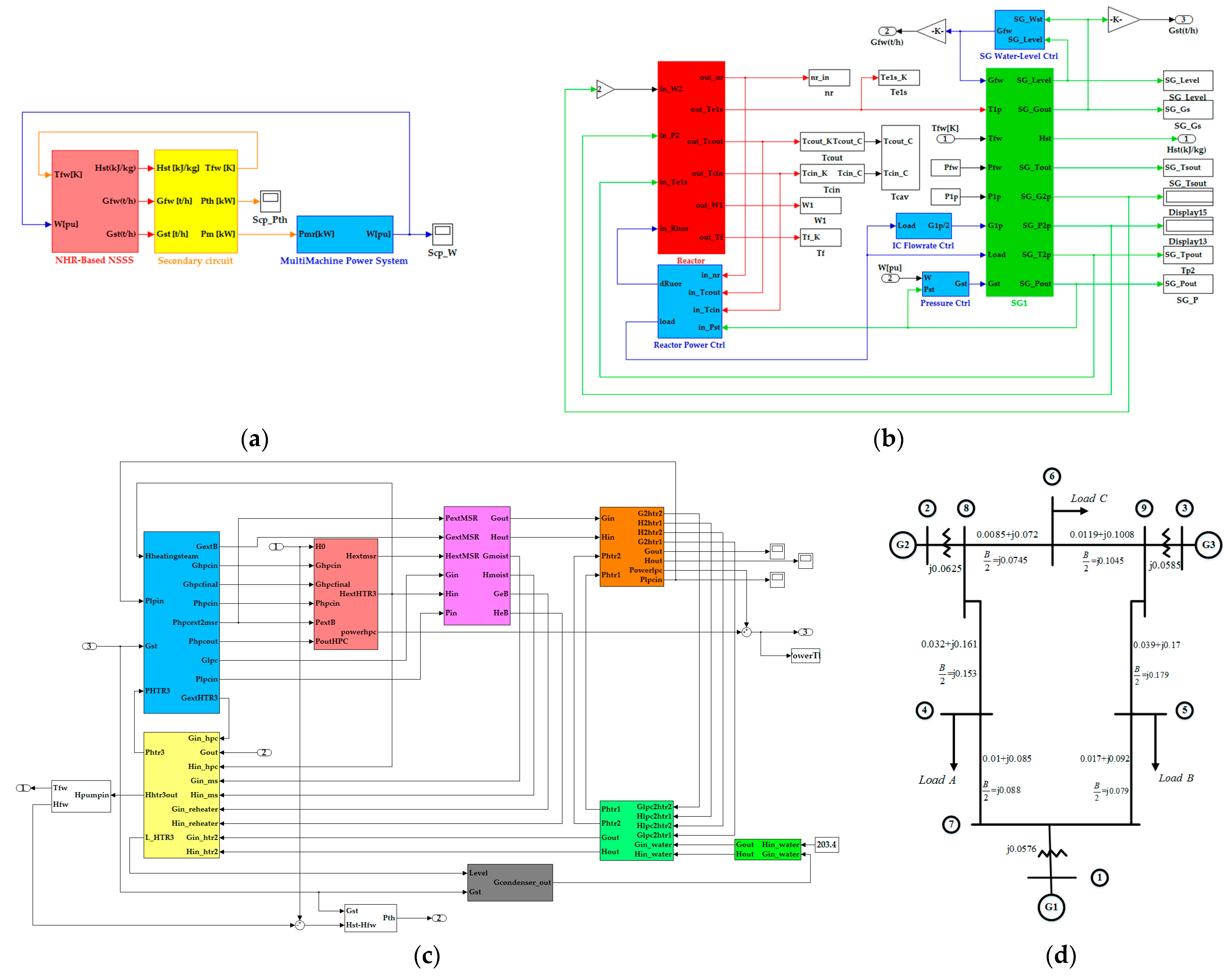
5.1. Simulation Program

Based upon the lumped-parameter dynamic model of NHR200-II reactor and secondary-circuit given in [18], the simulation program is developed in Matlab/Simulink for the verification of the AGC scheme and algorithm. The developed program is shown in Figure 5, where Figure 5a is the entire program, Figure 5b is the NSSS, Figure 5c is the secondary circuit, and Figure 5d is the multimachine power system with three machines and nine nodes. The synchronous generator of NHR plant is connected to the first node in this power grid. The algorithm for solving ordinary differential equations (ODEs) in this numerical simulation software is the variable-step ode23tb with a relative accuracy of 1 × 10⁻⁴. The control laws in this simulation for regulating the neutron flux, reactor core outlet temperature, and UTSG water level are those presented in [20,21].

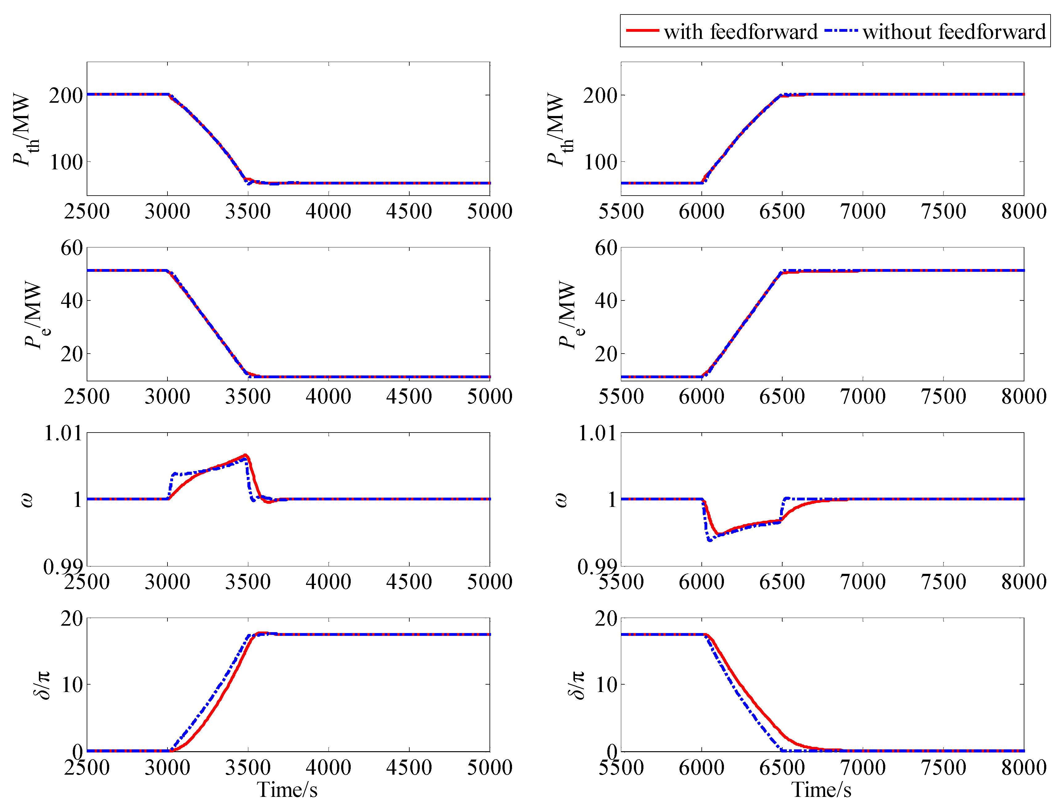
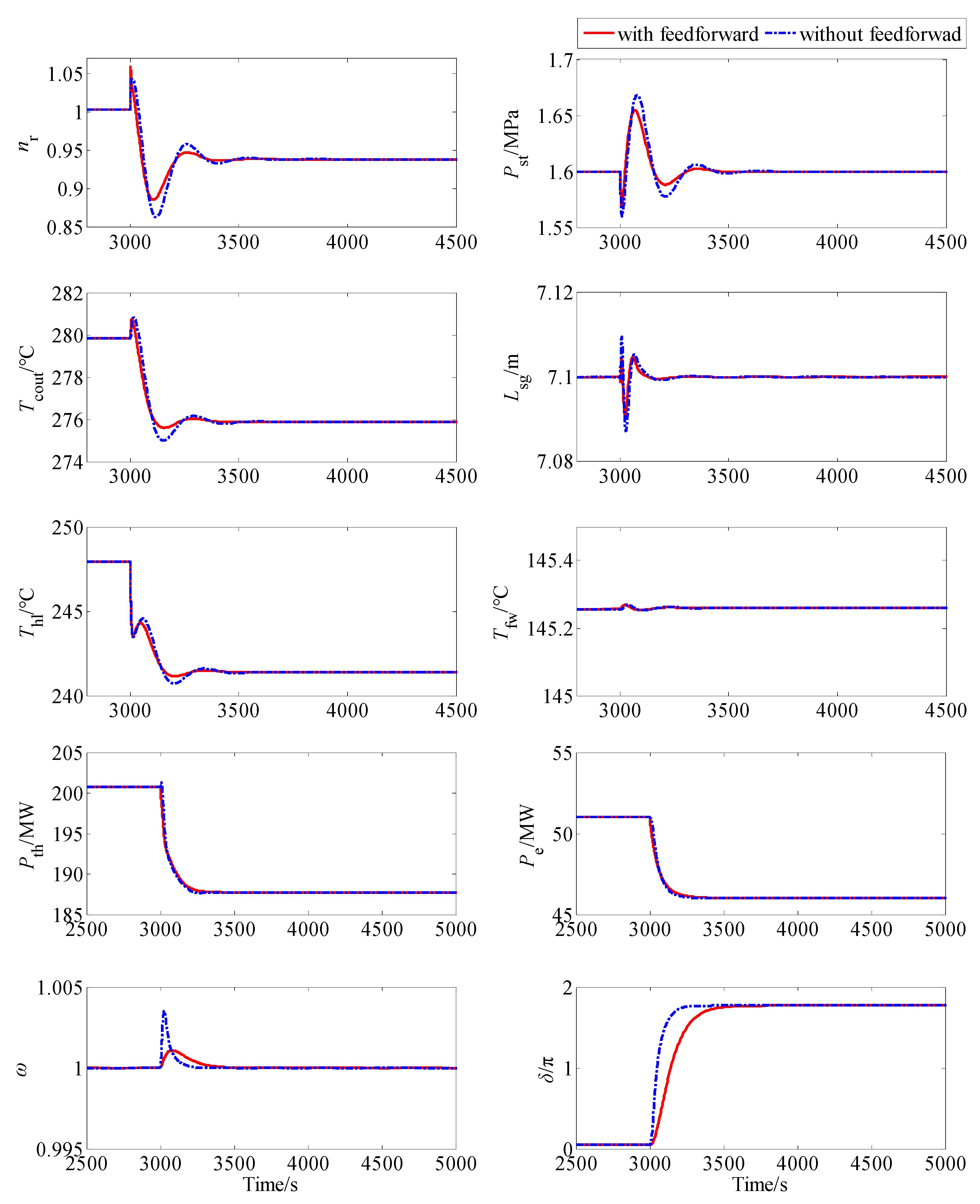
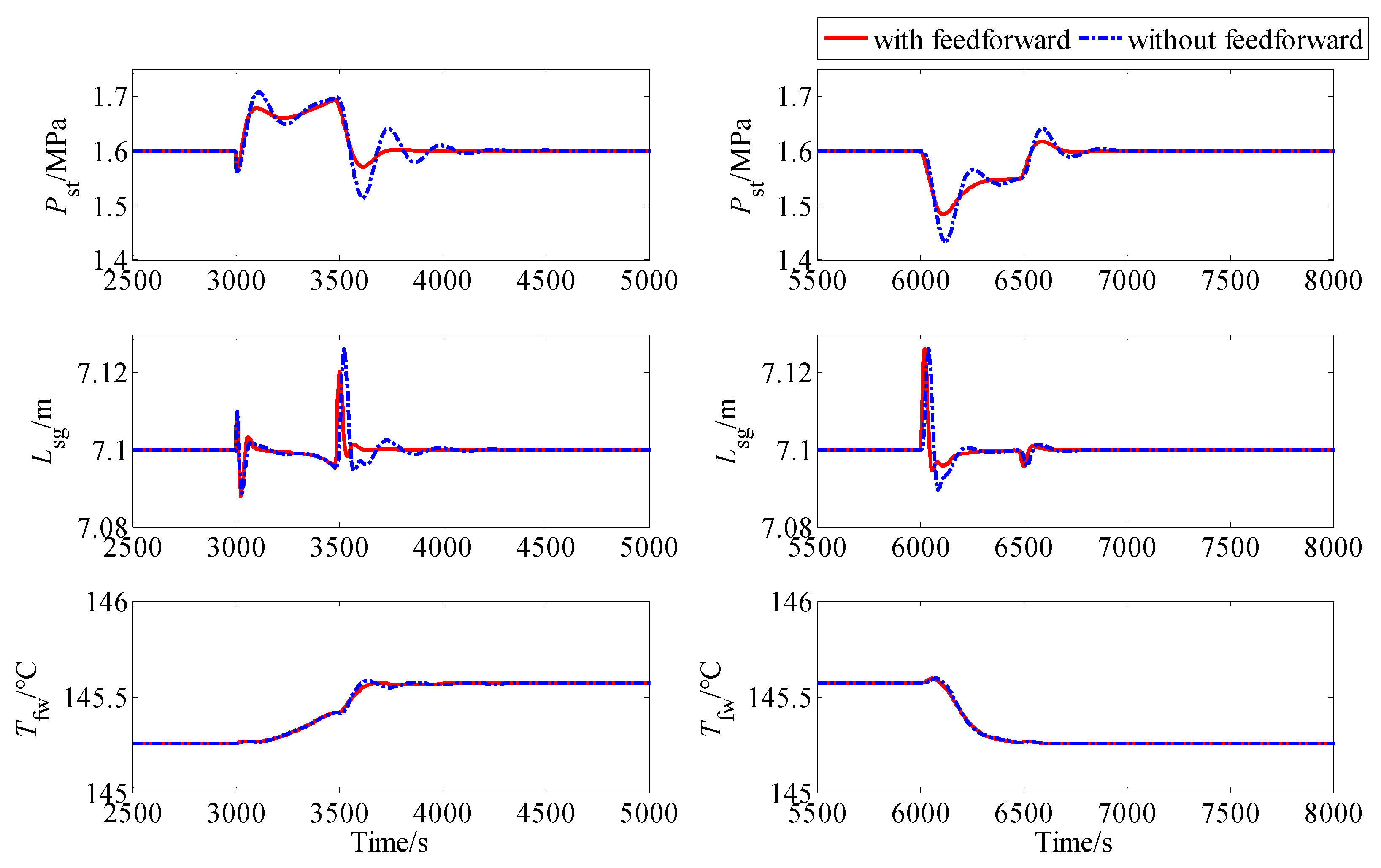
5.2. Simulation Results

The cases of both load stepping and ramping are considered in this numerical simulation experiment performed based on the program shown in Figure 5, and the corresponding simulation results about the dynamical responses of key process variables are given to show the AGC performance of the NHR-200II power plant.
1. Load Stepping
Initially, the NHR-200II plant operates at 100% plant full power (PFP), and then at 3000 s, load A at node 4 of multimachine power system shown in Figure 5d steps down with the amplitude of 5 MWe. The dynamical responses of the plant process variables such as the neutron flux, core outlet temperature, IC hot leg temperature, live steam pressure, UTSG water level and feedwater temperature, thermal power, electric power, normalized grid frequency, and phase angle are shown in Figure 6.
2. Load Ramping
The NHR-200II plant also operates at 100% plant full power (PFP) initially; load A at node 4 ramps down to the level of 10 MWe lower at 3000 s, and ramps up to its original level at 6000 s, where the ramping rate is 5 MWe/min. The plant dynamical responses of physical, thermal‒hydraulic, and electric parameters during load ramping are shown in Figure 7, Figure 8 and Figure 9.

5.3. Discussion

From Figure 6, as the electrical demand drops down, the frequency, i.e., the rotation rate of a synchronous generator increases abruptly, which enlarges the frequency error and further drives the frequency controller to narrow the main steam valve to a smaller opening so as to decrease the frequency. The decrease in the opening of the main steam valve leads to an increase in the live steam pressure, which drives the steam pressure controller to lower the setpoint of thermal power. The variation in referenced thermal power drives the thermal power control system composed of a reactor controller, IC flowrate controller, and UTSG water-level controller to regulate the neutron flux, core outlet temperature, IC flowrates, and water levels so that the actual thermal power can cope with its setpoint. From Figure 6, it can be clearly seen that ADRC (32) can guarantee satisfactory automatic generation performance. Moreover, as we see from Figure 6, the overshoots of steam pressure and frequency corresponding to the control law with feedforward term are much smaller than without. Actually, from Equation (32), the feedforward term is adopted to attenuate the total disturbance estimated by DO (33). If there is no feedforward action, the disturbance can lead to a deviation in process variables, which leads to an increase in variable overshoots. From the first subfigure of Figure 6, the feedforward term can also result in a slightly larger overshoot of neutron flux. However, due to the inherent safety features of NHR, this overshoot in neutron flux is acceptable.
Moreover, from Figure 7, Figure 8 and Figure 9, the ADRC can also provide satisfactory transient in response to the ramping down and up of electrical demand. As we see from Figure 9, the ADRC with feedforward action can provide a slower response of grid frequency than that without. Furthermore, from Figure 8, the feedforward action can lead to smaller overshoot and a smoother response of the main steam pressure. Since the variational rate of the thermal power setpoint in the case of load ramping is much smaller than that in the case of load stepping, the overshoot of neutron flux is much smaller. Then, we can see that the central role of feedforward term is to cancel out the disturbance based on the estimation provided by DO, which can result in the improvement of plant dynamical responses. Moreover, since ADRC without feedforward action is just the classical PI control law, it can be seen that the disturbance estimation and attenuation technique is an effective way to improve the control performance for nuclear power plants.
Finally, due to the simple expression of ADRC (32) and DO (33), they can be easily implemented on those digital control system platforms. Moreover, the ADRC without a feedforward term, i.e., a PI feedback law, is easier to deploy; however, the trade-off is a deterioration in control performance.

6. Conclusions

SMR is one of the main trends in nuclear energy, and iPWR such as Nuscale, SMART, and IRIS are among the most important types. The NHR developed by INET, Tsinghua University is also a typical iPWR with inherent safety features such as self-pressurization, full-power-range natural circulation, and hydraulic control rods. Due to its high level of nuclear safety, it can be adopted to balance the supply and demand of electric power for deepening the penetration of renewable energy resources such wind and solar, which result in the development of NHES. The key feature of NHES is the high flexibility of its NPPs, guaranteed by the AGC function of the plant control system. In this paper, the plant control system of an NHR power plant with AGC function is designed, where the AGC function is realized based on the stabilization of grid frequence and main steam pressure. Then an ADRC law is proposed for realizing the AGC function, which is composed of the feedback control action given by a PI law and the feedforward disturbance attenuation action driven by a well-designed DO. This newly built disturbance attenator is applied to realize the AGC function of the NHR-200II reactor power plant. Simulation results not only show indicate feasibility and satisfactory performance but also illustrate the influence of feedforward disturbance attenuation action on the dynamic responses.

Author Contributions

Conceptualization, Z.D.; Formal analysis, Z.D.; Funding acquisition, Z.D. and X.H.; Methodology, Z.D. and M.L.; Project administration, Y.Z. and Z.Z.; Software Z.D. and M.L.; Validation, D.J. and M.L.

Funding

This research was jointly supported by the Natural Science Foundation of China (NSFC) [Grant No. 61773228] and the National S&T Major Project of China [Grants No. ZX06902 and ZX06906].

Acknowledgments

The authors would like to thank deeply to the anonymous reviewers for constructive comments on this paper.

Conflicts of Interest

The authors declare no conflict of interest. The founding sponsors had no role in the design of the study; in the collection, analyses, or interpretation of data; in the writing of the manuscript; or in the decision to publish the results.

References

  1. Suman, S. Hybrid nuclear-renewable energy systems: A review. J. Clean. Prod. 2018, 181, 166–177. [Google Scholar] [CrossRef]
  2. Ponciroli, R.; Wang, Y.; Zhou, Z.; Botterud, A.; Jenkins, J.; Vilim, R.B.; Canda, F. Profitability evaluation of load-following nuclear units with physics-induced operation constraints. Nucl. Technol. 2017, 200, 189–207. [Google Scholar] [CrossRef]
  3. Lykidi, M.; Gourdel, P. Optimal management of flexible nuclear power plants in a decarbonizing competitive electricity market: The French case. Energy 2017, 132, 171–185. [Google Scholar] [CrossRef]
  4. Cany, C.; Mansilla, C.; da Mathonnière, C.P. Nuclear power supply: Going against the misconceptions. Evidence of nuclear flexibility from the French experience. Energy 2018, 151, 289–296. [Google Scholar] [CrossRef]
  5. Jenkins, J.D.; Zhou, Z.; Ponciroli, R.; Vilim, R.B.; Ganda, F.; de Sisternes, F.; Botterud, A. The benefits of nuclear flexibility in power system operations with renewable energy. Appl. Energy 2018, 151, 872–884. [Google Scholar] [CrossRef]
  6. Baker, T.E.; Epiney, A.S.; Rabiti, C.; Shittu, E. Optimal sizing of flexible nuclear energy system components considering wind volatility. Appl. Energy 2018, 212, 498–508. [Google Scholar] [CrossRef]
  7. Ingersoll, D.T. Deliberately small reactors and the second nuclear era. Prog. Nucl. Energy 2009, 51, 589–603. [Google Scholar] [CrossRef]
  8. Vujić, J.; Bergmann, R.M.; Škoda, R.; Miletić, M. Small modular reactors: Simpler, safer, cheaper? Energy 2012, 45, 288–295. [Google Scholar] [CrossRef]
  9. Rowinski, M.K.; White, T.J.; Zhao, J. Small and medium sized reactors (SMR): A review of technology. Renew. Sustain. Energy. Rev. 2015, 44, 643–656. [Google Scholar] [CrossRef]
  10. Ingersoll, D.T.; Houghton, Z.J.; Bromm, R.; Desportes, C. NuScale small modular reactor for co-generation of electricity and water. Desalin 2014, 340, 84–93. [Google Scholar] [CrossRef]
  11. Wang, D.; Ma, C.; Dong, D.; Lin, J. Chinese nuclear heating test reactor and demonstration plant. Nucl. Eng. Des. 1992, 136, 91–98. [Google Scholar]
  12. Wang, D.; Zhang, D.; Dong, D.; Gao, Z.; Li, H.; Lin, J.; Su, Q. Experimental study and operation experiences of the 5 MW nuclear heating reactor. Nucl. Eng. Des. 1993, 143, 9–18. [Google Scholar]
  13. Wang, D. The design characteristics and construction experiences of the 5 MW nuclear heating reactor. Nucl. Eng. Des. 1993, 143, 19–24. [Google Scholar]
  14. Wang, D.; Zheng, W. Technical design features and safety analysis of the 200 MW nuclear heating reactor. Nucl. Eng. Des. 1993, 143, 1–7. [Google Scholar]
  15. Wang, D.; Dong, D.; Zheng, W. The 200 MW nuclear heating reactor and its possible application in seawater desalination. Desalin 1994, 99, 367–381. [Google Scholar] [CrossRef]
  16. Zheng, W.; Wang, D. NHR-200 nuclear energy system and its possible applications. Prog. Nucl. Energy 1995, 29, 193–200. [Google Scholar]
  17. Li, W.; Zhang, Y.; Zheng, W. Investigation on three seawater desalination processes coupled with NHR-200. Desalin 2012, 298, 93–98. [Google Scholar] [CrossRef]
  18. Dong, Z.; Pan, Y. A lumped-parameter dynamical model of a nuclear heating reactor cogeneration plant. Energy 2018, 145, 638–656. [Google Scholar] [CrossRef]
  19. Li, G.; Wang, X.; Liang, B.; Li, X.; Zhang, B.; Zou, Y. Modeling and control of nuclear reactor cores for electricity generation: A review of advanced technology. Renew. Sustain. Energy Rev. 2016, 60, 116–128. [Google Scholar] [CrossRef]
  20. Dong, Z. PD power-level control design for PWRs: A physically-based approach. IEEE Trans. Nucl. Sci. 2013, 60, 3889–3898. [Google Scholar] [CrossRef]
  21. Dong, Z.; Huang, X.; Feng, J. Water-level control for the U-tube steam generator of nuclear power plants based on output feedback dissipation. IEEE Trans. Nucl. Sci. 2009, 56, 1600–1612. [Google Scholar] [CrossRef]
Figure 1. Schematic structure of nuclear heating reactor (NHR).
Energies 11 02782 g001
Figure 2. Shematic process diagram of the nuclear heating reactor (NHR)-based power plant.
Energies 11 02782 g002
Figure 3. Control scheme diagram of nuclear heating reactor (NHR) power plant.
Energies 11 02782 g003
Figure 4. Control scheme diagram of PWR power plant.
Energies 11 02782 g004
Figure 5. Simulation program and the corresponding three-machines/nine-nodes power system: (a) whole plant, (b) simulation unit of NSSS, (c) simulation unit of secondary system, (d) power system.
Energies 11 02782 g005
Figure 6. Responses of key process variables in the case of load stepping, nr: neutron flux, Tcout: core outlet temperature, Thl: IC hot leg temperature, Pst: live steam pressure, Lsg: UTSG water-level, Tfw: feedwater temperature, Pth: thermal power, Pe: electric power, ω: normalized frequency, and δ: phase angle.
Energies 11 02782 g006
Figure 7. Responses of PC and IC process variables in the case of load maneuvering, nr: neutron flux, Tcout: core outlet temperature, Thl: IC hot leg temperature.
Energies 11 02782 g007
Figure 8. Responses of UTSG process variables in the case of load maneuvering, Pst: live steam pressure, Lsg: UTSG water-level, Tfw: feedwater temperature.
Energies 11 02782 g008
Figure 9. Responses of electric variables in the case of load maneuvering, Pth: thermal power, Pe: electric power, ω: normalized frequency, and δ: phase angle.
Energies 11 02782 g009
Table 1. Main design parameters of NHR-200 and NHR-200II.
ParameterUnitNHR-200NHR-200II
Thermal PowerMWth200200
Coolant/Moderator Light WaterLight Water
Circulation Type Natural CirculationNatual Circulation
Primary Circuit PressureMPa2.58
Core Inlet/Outlet Temperature °C145/210232/280
Intermediate Circuit PressureMPa3.08.8
IC Cold/Hot Leg Temperature °C95/145203/248
Live Steam PressureMpa0.251.6
Live Steam Temperature°C127.4201.4

