Dynamic Matrix Control for the Thermal Power of MHTGR-Based Nuclear Steam Supply System


Institute of Nuclear and New Energy Technology, Collaborative Innovation Centre of Advanced Nuclear Energy Technology, Key Laboratory of Advanced Reactor Engineering and Safety of Ministry of Education, Tsinghua University, Beijing 100084, China
*
Author to whom correspondence should be addressed.
Energies 2018, 11(10), 2651; https://doi.org/10.3390/en11102651
Submission received: 14 September 2018
/
Revised: 30 September 2018
/
Accepted: 1 October 2018
/
Published: 4 October 2018
(This article belongs to the Special Issue Nuclear Power, Including Fission and Fusion Technologies)
Abstract
:The modular high temperature gas-cooled reactor (MHTGR) based nuclear steam supplying system (NSSS) is constituted by an MHTGR, a once-through steam generator (OTSG) and can generate superheated steam for industrial heat or electric power generation. The wide range closed-loop stability is achieved by the recently proposed coordinated control law, in which the neutron flux and the temperatures of both main steam and primary coolant are chosen as controlled variables, and the flowrates of both primary and secondary loop and the control rod speed are chosen as manipulated variables. However, the thermal power is only controlled in open loop manner and hence could be further optimized through feedback. Motivated by this, a dynamic matrix control (DMC) is proposed for optimizing the thermal power of MHTGR based NSSS. A simple step-response model with the thermal power response data is utilized in designing the DMC. The design objective of DMC is to optimize the deviation of the thermal power from its reference under its rate constraint. Then, by the virtue of strong stability of existing control law and optimization ability of DMC, a cascade control structure is implemented for the thermal power optimization, with the coordinated control law in the inner loop and DMC in the outer loop. Numerical simulation results show the satisfactory improvement of thermal power response. This cascade control structure inherits the advantages of both proportional-integral-differential (PID) control and DMC, by which the zeros offset and the short settling time of thermal power are realized.
1. Introduction
Nuclear steam supply system (NSSS), which utilizes the nuclear fission to produce high-pressure steam and then to drive some thermal load devices, occupies an important role in nuclear power plants (NPPs). Modular high temperature gas-cooled reactor (MHTGR) is a representative small modular reactors (SMRs) and has received a lot of attention due to its virtues of inherent safety and strongly efficient energy source [1,2]. A MHTGR-based NSSS module consisted of a helical-coil once-through steam generator (OTSG), a one-zone pebble-bed MHTGR arranged side-by-side with the OTSG is shown in Figure 1. The power-level control of MHTGR-based NSSS, which regulates the neutron flux, temperatures of both helium and steam by changing the control rod speed, rotation-rate of feed water pump and helium blowers, is a critical technique for the efficient and safe operation of NPPs. Currently, in China, stimulated by the need in the carbon emission reduction, local power demand and heat sources for industrial complexes, control performance optimization and guaranteed inherent stability are two promising directions of MHTGR-based NSSS power control [3].
During load-following operation of NPPs, the severe nonlinearity and model uncertainty of NSSS dynamics have resulted in stability issue to NSSS power control engineers. In the past two decades, particular concern has been given to the NSSS or reactor power control. Some promising nonlinear control (NC) methods have been developed, e.g., the sliding mode control introduced by Shtessel, Huang, Qaiser and Ansarifar [4,5,6,7], the physics-based techniques given by Dong [8,9], and the feedback linearization method with disturbance observer proposed by Eom [10]. The previous works [4,5,6,7,8,9,10] show satisfactory results in enhancing closed-loop stability and robustness for NPPs. However, since most reported works are only focused on stability issues of NPPs operation, the operational efficiency needs to be further optimized.
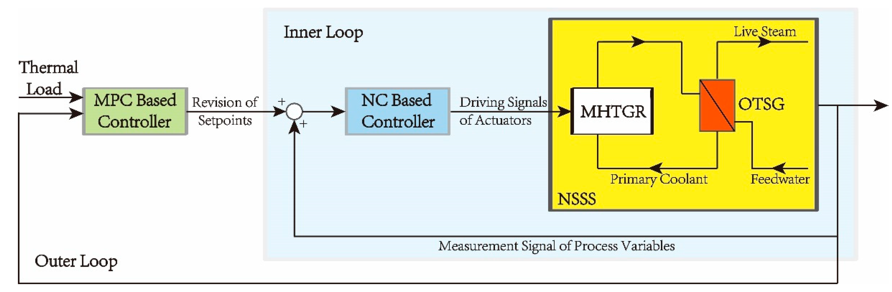
Model predictive control (MPC) belongs to a class of optimal control methods that generate a sequence of control inputs based on an explicit mathematical model for a finite future and has made a significant impact on energy control systems [11,12]. The main advantage of MPC is its ability to improve the operational efficiency while explicitly taking physical constraints into controller design. The first MPC design in the nuclear reactor control field was the work proposed by Na et al. [13], and, since then, the application of MPCs in power-level control of NPPs were deeply studied [14,15,16,17]. However, to guarantee the robustness and closed-loop stability of MPC, more constraints must be involved, which may lead to numerical issues and hence impede the industrial practice [18]. Based on the above analysis, a natural and attractive way to take both optimization and stability into consideration, is to combine the MPC-based optimizer and NC-based stabilizer together forming the cascade control structure shown in Figure 2. However, the existing MPCs [13,14,15,16,17] directly take the process variables (control rod, pump, etc.) as the manipulated variables, which implies that these MPCs have to play the role of both optimizer and stabilizer, and hence cannot be utilized for the cascaded control with NC. Therefore, the investigation of an optimization-oriented MPC with cascade connection to NC-based stabilizers, is promising.
Furthermore, an accurate mathematical model with reasonable modeling cost is the prerequisite for successful MPC application. Because of the model complexity, parameterized models, including nonlinear model derived by first principles, local linearization of a nonlinear physical model and controlled autoregressive and integrated moving average (CARIMA) model, etc., are widely utilized in different kinds of MPCs design for NSSS power control [13,16,17]. However, due to the strong uncertainty, nonlinearity and complexity, an MPC-oriented parameterized model of MHTGR-based NSSS is very difficult to develop. To get an efficient mathematical model, the data-based modeling approach, which gives mathematical models based on operational data, are investigated extensively [3,19]. One widely used nonparametric model in the field of MPC is step-response model and the corresponding MPC is the so-called dynamic matrix control (DMC). The data for building the step response model are very easy to access and the coding of DMC algorithm is relatively simple to be implemented by computer and has been applied to many industrial processes [20,21]. Many commercial software packages have been developed based on step-response model including RMPCT, DMC+, HIECON and SMC [22]. However, there are still few DMC reports of NSSS power control, thus it is meaningful to generate the step-response model from the operational data for the DMC design.
According to the cascade structure shown in Figure 2, the NC proposed in Reference [9] is considered as stabilizer in the inner loop. Although the wide range closed-loop stability can then be achieved by regulating the temperatures of both main steam and helium as well as neutron flux, by means of adjusting the control rod speed, rotation-rate of feed water pump and helium blowers, the thermal power is controlled in the open loop manner. Since the thermal power response represents the energy balance between the turbine and NSSS, it is significant to ensure a desirable thermal power transience. Motivated by this, for the outer loop, a DMC is newly designed for MHTGR-based NSSS thermal power control. This scheme has the following three features. First, a DMC is design over the existing NC. Second, the thermal power response by this cascade control is insensitive to the parameter data of NSSS step-response model. Third, both the zero offset and the short settling time of thermal power are realized. The results of numerical simulation under both wide range power ramp conditions show the improved thermal power response of this newly-built DMC cascade control scheme.
2. MHTGR-Based NSSS
2.1. System Description
Figure 1 shows the diagram of one MHTGR-based NSSS module designed by Institute of Nuclear and New Energy Technology in Tsinghua University [23] and has been extensively analyzed and referred to in many studies [2,3,8,9]. The MHTGR-based NSSS module mainly consists of coherently connected submodules, which are described by neutron kinetic, heat transfer, and hydrodynamic equations. Therefore, the overall MHTGR-based NSSS is extremely complicated and is modeled in the MATLAB environment.
The MHTGR utilizes helium as primary loop coolant and graphite as both the moderator and structural material. As shown in Figure 1, cold helium is pressurized in the blower, which is installed on the top of OTSG, and then the pressurized helium leaves the OTSG to enter the MHTGR through the cold gas pipeline. The cold helium rises along the channel inside the reflector from the bottom to the top to cool down the reflector, and then falls vertically through the pebble bed. During this process, the enormous amounts of thermal energy from fission is absorbed by the helium, which is heated to a very high temperature. The hot helium reaches the chamber in the bottom of reflector and then flows into the primary side of OTSG, where it is cooled down by transferring heat to the secondary steam stream and flows toward the blower as cold helium again. The main design parameters of the MHTGR-based NSSS are listed in Table 1.
2.2. Inner Loop Control Scheme
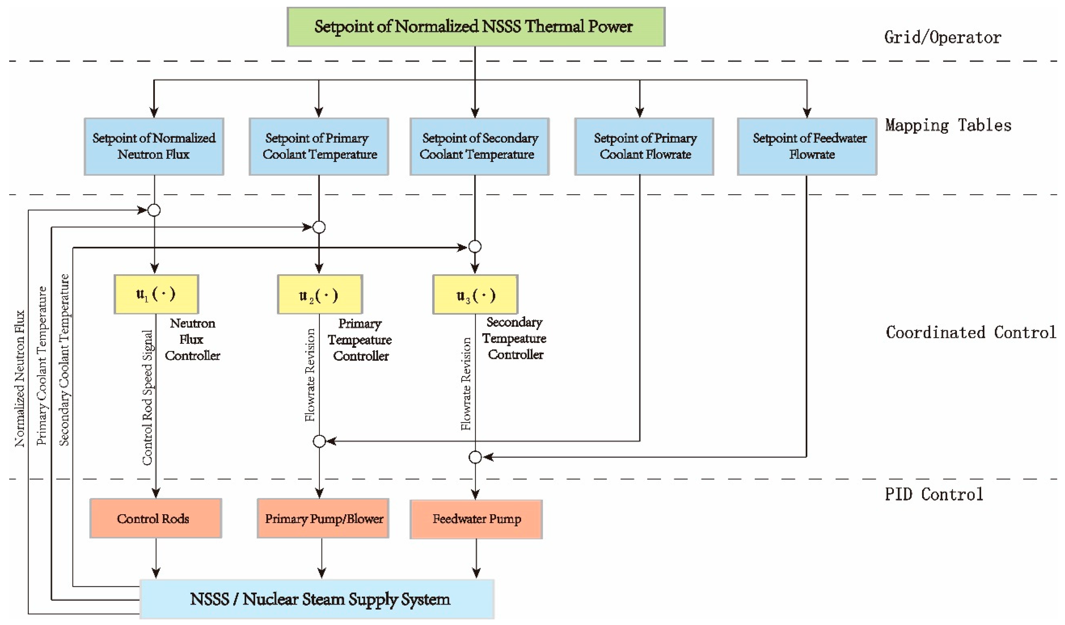
The MHTGR-based NSSS is a tightly coupled system with multiple inputs and multiple outputs. To guarantee the closed-loop stability, a coordinated control scheme is shown in Figure 3 [9] with the control input and output listed in Table 2.
The set-point of NSSS thermal power is given by the load demand which is determined by manual setting from operator, load frequency control or the peak adjustment from the power grid. In Figure 3, the neutron flux controller adjusts the rod speed to follow the nuclear power set-point by changing the reactivity in the core. The primary temperature controller utilizes the deviation of both primary and secondary temperature from their set-points to compute the revision of helium flowrate. The secondary temperature controller determines the revision of feedwater flowrate and forms a cascade structure with connection to the inner loop feedwater flowrate controller.
The mapping tables is a static mapping from the set-point of thermal power to the set-points of flowrates, neutron flux and temperatures. Moreover, the mapping tables depends on the thermal-hydraulic and physical design and is implemented online through a look-up table. Thus, the set-point trajectories fed to the coordinated control in Figure 3 are just generated by simple linking of the steady values of flowrates, neutron flux and temperatures and obviously can only reflect the balance between the nuclear power and thermal power of NSSS in the steady-state.
2.3. Problem Formulation
The satisfactory closed-loop stability of both neutron flux and temperatures can be guaranteed by the control scheme shown in Figure 3. However, the thermal power is controlled in the open loop manner, as shown in Figure 4. The heat capacities of submodules such as reflector, pebble bed, and OTSG have significant difference. Thus, eliminating the errors of flowrates, neutron flux and temperatures from their set-point given by mapping tables may not produce a desirable thermal power response.
3. Dynamic Matrix Control for Thermal Power
Due to the characteristics of zero offset property, small computation burden and strong robustness, DMC is considered as optimization-oriented controller in the outer loop. The standard method is adopted in the design of DMC [20,21], namely the step response model, optimization, and estimator.
3.1. Cascade Control Scheme
The proposed cascade control scheme is shown in Figure 5, where , , , and are unit delay block, thermal load, its derivative and derivative revision of the thermal load, respectively. Obviously, compared with the coordinated control law shown in Figure 3, DMC is added in the outer loop to form a cascade structure, which is explained in the following subsections. The aim of DMC is, at every sampling instant, to inject a first derivative revision signal to the first derivative of thermal load.
Remark 2.
The first derivative signal of thermal load instead of its step signal, which is a more common choice in MPC industrial application area, is considered in Figure 5 and is explained below. The principle for designing the DMC is not to change the original controller structure, which means the DMC should give the revision signaland superposes with original thermal load signal. Thus, the thermal load signalfed to the mapping tables is chosen to be,
A potential constraint from Equation (2) is thatandshould be fed to mapping tables at the same sampling rate. However, sinceis given by DMC, the sampling rate is usually one or two orders of magnitude slower than, whose sampling rate is usually the same as PID, in millisecond range. Hence, by choosing first derivative signal, DMC can work efficiently cascaded with PID at different sampling rate, and give a relatively smooth thermal load signal [24].
3.2. Step Response Model
3.2.1. Step Signal Test
To build the step response model of thermal power, a step signal is applied to the first derivative of thermal load, as shown in Figure 6, and the resultant thermal power response data are then stored. At the steady state of 50% reactor full power (RFP), the derivative of thermal load is increased by 1%FP/min and the step responses of thermal power are shown in Figure 7.
When the reference derivative signal is increased by 1%FP/min at 𝑡 = 90,000 s, thermal power is increased to track the ramp controlled by the inner loop controller, and gradually reaches a “stable state” for about 200 s. From the perspective of modeling cost, step response model can be easily built based on the existing control system and the implementation of DMC is relatively simple. The thermal power step response is sampled at every sampling instant and is stored in step response coefficient matrix
where is the amplitude of thermal power step response at the th sampling step and is the sampling number.
Remark 3.
In Figure 7, the “stable state” after about 200 s transient implies that the future thermal power can be approximate fitting by a linear affine function. Thus, it is reasonable to truncate the step response when thermal power response has reached the “stable state”.
3.2.2. State Space Model
By the observation of Figure 7, suppose the dynamic response of thermal power enters the “steady state” after sampling time under a step input. Then, as discussed in Remark 3,
where is thermal power and is sampling instant. To obtain a state space model, define the state at th sampling instant as,
where and are the derivative revision signal and derivative variation of thermal load , respectively. Thus, the free thermal power response is,
where
Based on the coefficient matrix , the state space model can then be represented by,
where .
3.3. Optimization
The goal of the optimization (see Figure 5) is to calculate a sequence of derivative revision signals such that the prediction of thermal power tracks the thermal load in a desirable manner under the inequality constraints on the thermal power rate. The desirable sequence of derivative revisions is obtained by minimizing a cost function, appropriately defined over a finite future as follows:
subject to the following.
Initial State:
Prediction Equations:
Constrains on Input:
The objective function takes the following quadratic form:
where represents the numerical value of the variable obtained at the sampling instant , based on current measurements and information at instant . , , and are prediction horizon, control horizon, maximum and minimum value of thermal power rate, respectively. is the estimation of the system state derived from an estimator, which is given in next subsection.
By solving the optimization problem in Equation (9), although more than one optimal derivative revision signal is obtained, only the first portion is implemented. At the next sampling instant, when the new system state is ready, the above optimization is then repeated.
Remark 4.
The constrained optimization problem in Equation (9), with objective function given by Equation (10) can boil down to a quadratic program (QP) and is available to be solved efficiently by commercial software [25].
3.4. Estimator
Since only the first portion of can be measured, it is necessary to estimate the state of the model in Equation (8). As shown in Figure 5, the estimator is given as,
where is the gain of the estimator.
Remark 5.
The controllability and observability of the model in Equation (8) can be easily validated by checking the following algebraic expression,
Remark 6.
In general, the error dynamics of the estimator is,
whereis the model mismatch between the step response coefficient matrix stored in Equation (3) and the true thermal power dynamic. Thus, theshould be chosen to makenominal asymptotically stable.
3.5. Tuning of the DMC
Theoretically, large prediction and control horizon together with small sampling time are preferred, which increases the online computational burden for solving QP (Equation (9)). Usually, the sampling time of discrete control should be no more than 10% of the minimum time constant and the prediction horizon should be long enough to cover the whole thermal power dynamic response. In Figure 7, the sampling time is chosen to be 5 s for the DMC design.
The two terms in the cost function in Equation (10) are expressed as and , which indicate the error for thermal power and the change in the derivative revision signal, respectively. The goal is to find that is small (if possible) and makes the residual small. Then, a positive parameter is added in the objective function in Equation (10) to minimize the weighted sum of squared norms. In the DMC, a large value of should be selected due to the following considerations:
- large value adds the cost of using large values of the derivative revision signal, to the cost of missing a small amount of the thermal power tracking. Since the step response coefficient matrix is sampled around a specified operating point, the inevitable model error makes it meaningless to tune the parameter aggressively by solving the QP.
- By solving Equation (9), small value of may result in a large . From Equation (13), a large causes large variation in estimator error, and hence should be avoided.
4. Application to NSSS Thermal Power Control
In this section, the designed DMC consisting of Equations (9) and (11) is applied for the thermal power control of a MHTGR-based NSSS module. The numerical simulation results of power ramping between 100% and 50% RFP are shown, and necessary discussions are also provided.
4.1. Implementation of DMC
Figure 5 shows the proposed DMC for optimizing the thermal power of the MHTGR-based NSSS module, which has a classical cascade control structure with DMC in the outer loop for optimization and the PID in the inner loop for stabilization. The input and output of the DMC are the thermal power measurements with its reference and the derivative revision signal to the set-point of thermal power, respectively. The gain of the estimator is based on the duality principle, and a linear quadratic regulator (LQR) feedback gain for system is chosen. In the DMC, the QP is solved using the MATLAB function “quadprog” at each sampling instant. Although the numerical simulation is performed on a personal computer, the computation speed is very fast and negligible compared with the sampling time. Thus, the proposed DMC can be easily implemented in real-time without any further code optimization.
4.2. Simulation Setting and Results
This simulation and the step test in Figure 7 are executed on the MATLAB/Simulink environment, and the simulation program is the same as that given in Reference [9], which consists of the dynamic modules of the OTSG, MHTGR and secondary loop fluid network [26]. The parameters of the PID controller are the same with those given in Reference [9]. The parameters of the DMC are given as , , , FP/Min, and FP/Min.
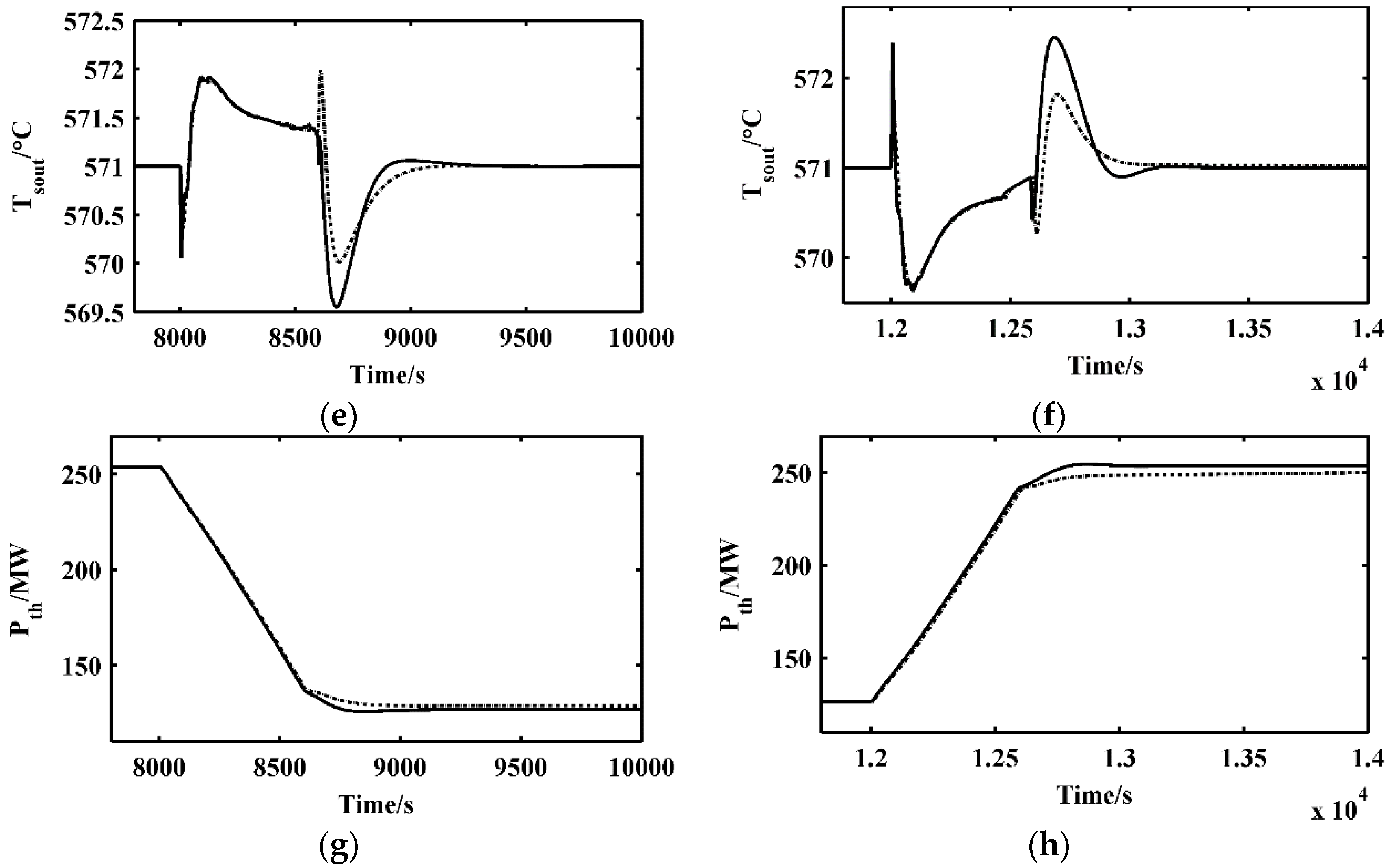
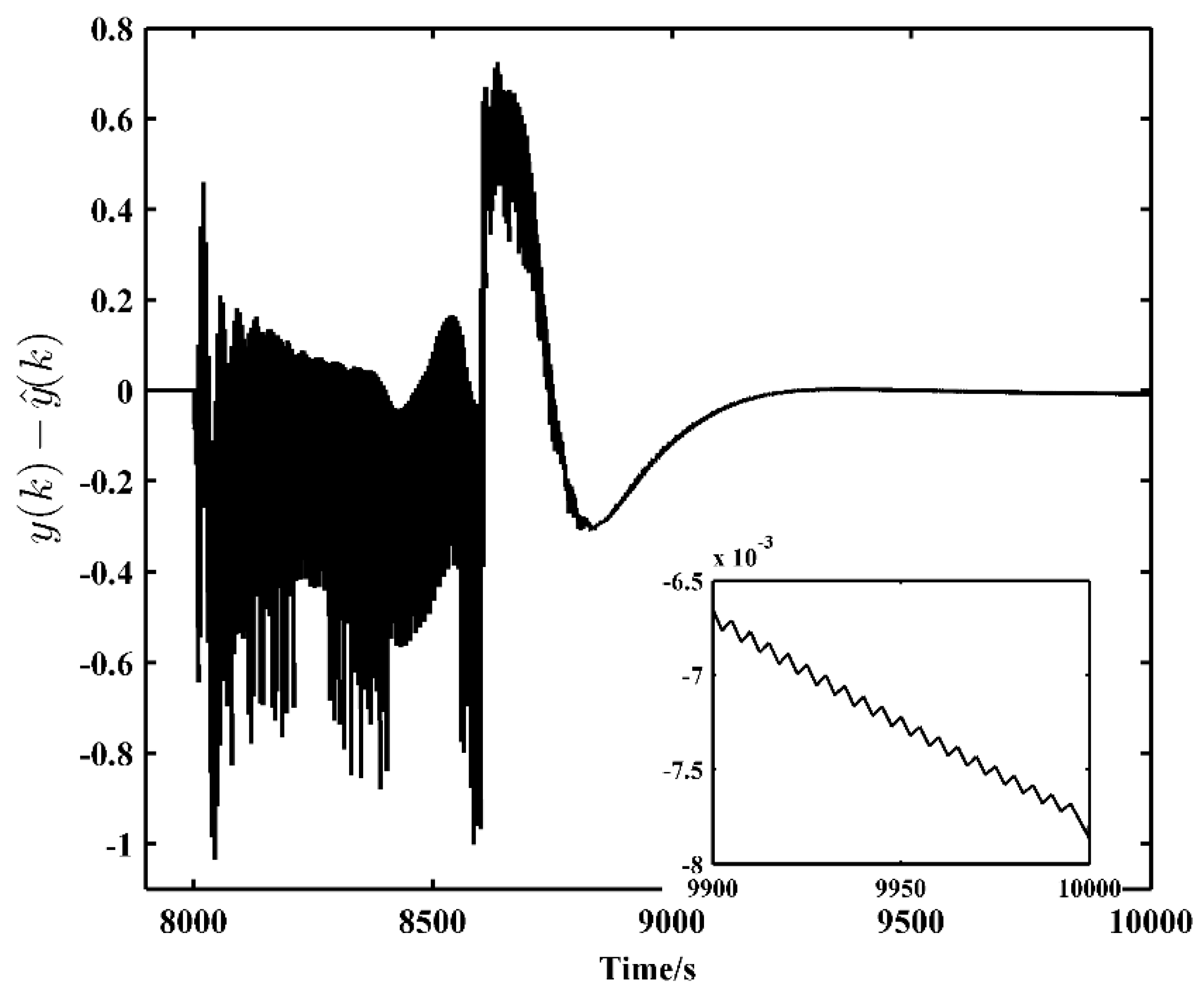
The simulation results of power ramping between 100% and 50% RFP are shown here. Initially, the MHTGR-based NSSS module operates at RFP. The thermal power set-point begin to ramp down from 100% to 50% RFP with the rate of 5% RFP/min manually set by operator at 8000 s, and then ramp up to 100% RFP also with the same rate at 12,000 s. The dynamic responses of the normalized nuclear power, the temperatures of both reactor outlet helium and OTSG steam, and the thermal power with and without DMC are shown in Figure 8. The dynamic responses of control rod speed, the flowrates of helium and feedwater with and without the DMC as well as revision of thermal power derivative revision signal are shown in Figure 9. The error dynamic of the estimator between true state and estimated state is shown in Figure 10.
4.3. Discussion
In the thermal power ramping simulation of NSSS module, the change in the set-point of thermal power directly causes the change in the set-points of flowrates, neutron flux and temperatures. The errors between actual values and their set-points are then enlarged. Immediately, proper set-points of the flowrates and the control rod speed are generated by the inner loop PID controller to suppress these errors. Obviously, the NSSS thermal power is not directly controlled by the PID, which is important to improve to keep the energy balance between the second loop and NSSS. To improve the transient performance of thermal power, the DMC shown in Figure 5 is implemented in the outer loop, whose input and output are, respectively, the tracking error of thermal power and the derivative revision to the set-point of thermal power. In Figure 8 and Figure 9, by adding the DMC in the outer loop, a slight overshoot can be observed in helium and feedwater flowrate, thermal power, helium temperature and neutron flux. The zeros offset and the short settling time of thermal power are realized while the closed-loop stability is well maintained.
The reasons for the different thermal responses with and without DMC are analyzed as follows. In the case without DMC, when the set-point of thermal power reaches the reference, then the set-points of neutron flux, temperature and flowrate remain unchanged. With these key variables approaching the set-points, input errors of PID gradually decreases, and thus the function of the PID is gradually diminished. Due to the great inertia delay between nuclear power and thermal power, the dynamic characteristics of thermal power is very slow to approach its reference, as shown in Figure 8. Here, the DMC in the outer loop is responsible for computing thermal power derivative revision signal at every sampling instant. Then, the set-points of nuclear flux, temperature and flowrate is revised by thermal power measurement in real time setting, thus better power balance between nuclear power and thermal power can be obtained.
Only one linear model (Equation (8)), developed at 50% RFP, is utilized to predict the thermal power within the prediction horizon. Then, QP is solved online to optimize the error between the predicted thermal power trajectory and thermal power setpoint while keeping the derivative revision signal relatively small. According to Equation (13), a bias between true state and estimated state is seen in Figure 10. The robustness of the DMC is validated by the simulation results and is enhanced by updating the estimated state given by Equation (11), at every sampling time so that the modeling error is partially compensated.
5. Conclusions
In this paper, DMC is proposed to improve the thermal power response of MHTGR based NSSS. From the viewpoint of the modeling cost, DMC is very simple and easy to develop. Moreover, this DMC can be implemented by leaving the current PID controller in the inner loop and optimizing the thermal power in the outer loop. Wide range power maneuverings were performed with large-scale Simulink models. The proposed method outperformed existing PID, which is designed mainly for stabilizing the NSSS system, and show the satisfactory improvement in the thermal power response. The thermal performance was only mildly affected by nonparametric model mismatch. This cascade control structure inherits the advantages of both PID and DMC, by which the zeros offset and the short settling time of thermal power are realized.
Author Contributions
Conceptualization, Z.D.; Formal analysis, D.J.; Funding acquisition, Z.D.; Methodology, D.J.; Project administration, Z.D. and X.H.; Software, M.L.; Validation, D.J. and M.L.
Funding
This work was jointly supported by Natural Science Foundation of China (NSFC) (Grant No. 61773228) and National S&T Major Project of China (Grant Nos. ZX06902 and ZX06906).
Conflicts of Interest
The author declares no conflict of interest. The founding sponsors had no role in the design of the study; in the collection, analyses, or interpretation of data; in the writing of the manuscript, and in the decision to publish the results.
References
- Lanning, D.D. Modularized high-temperature gas-cooled reactor systems. Nucl. Technol. 1989, 88, 139–156. [Google Scholar] [CrossRef]
- Wu, Z.; Lin, D.; Zhong, D. The design features of the HTR-10. Nucl. Eng. Des. 2002, 218, 25–32. [Google Scholar] [CrossRef]
- Dong, Z.; Zhang, Z.; Dong, Y.; Huang, X. Multi-layer perception based model predictive control for the thermal power of nuclear superheated-steam supply systems. Energy 2018, 151, 116–125. [Google Scholar] [CrossRef]
- Shtessel, Y.B. Enhanced Sliding mode control of the space nuclear reactor system. IEEE Trans. Aero. Electron. Syst. 1998, 34, 579–589. [Google Scholar] [CrossRef]
- Huang, Z.; Edwards, R.M.; Lee, K.Y. Fuzzy-adapted recursive sliding-mode controller design for a nuclear power plant control. IEEE Trans. Nucl. Sci. 2004, 51, 256–266. [Google Scholar] [CrossRef]
- Qaiser, S.H.; Bhatti, A.I.; Iqbal, M.; Samar, R.; Qadir, J. Model validation and higher order sliding mode controller design for a research reactor. Ann. Nucl. Energy 2009, 36, 37–45. [Google Scholar] [CrossRef]
- Ansarifar, G.R.; Rafiei, M. Higher order sliding mode controller design for a research nuclear reactor considering the effect of xenon concentration during load following operation. Ann. Nucl. Energy 2015, 75, 728–735. [Google Scholar] [CrossRef]
- Dong, Z. Physically-based power-level control for modular high temperature gas-cooled reactors. IEEE Trans. Nucl. Sci. 2012, 59, 2531–2549. [Google Scholar] [CrossRef]
- Dong, Z.; Pan, Y.; Zhang, Z.; Dong, Y.; Huang, X. Model-free adaptive control for nuclear superheated-steam supply systems. Energy 2017, 135, 53–67. [Google Scholar] [CrossRef]
- Eom, M.; Chwa, D.; Baang, D. Robust disturbance observer-based feedback linearization control for a research reactor considering a power change rate constraint. IEEE Trans. Nucl. Sci. 2015, 62, 1301–1312. [Google Scholar] [CrossRef]
- Han, S.; Sun, L.; Shen, J.; Pan, L.; Lee, K.Y. Optimal Load-Tracking Operation of Grid-Connected Solid Oxide Fuel Cells through Set Point Scheduling and Combined L1-MPC Control. Energies 2018, 11, 801. [Google Scholar] [CrossRef]
- Kong, X.B.; Liu, X.J.; Lee, Y.K. Nonlinear multivariable hierarchical model predictive control for boiler-turbine system. Energy 2015, 93, 309–322. [Google Scholar] [CrossRef]
- Na, M.G.; Shin, S.H.; Kim, W.C. A model predictive controller for nuclear reactor power. Nucl. Eng. Technol. 2003, 35, 399–411. [Google Scholar] [CrossRef]
- Na, M.G.; Upadhyaya, B.R. Application of model predictive control strategy based on fuzzy identification to an SP-100 space reactor. Ann. Nucl. Energy 2006, 33, 1467–1478. [Google Scholar] [CrossRef]
- Na, M.G.; Hwang, I.J.; Lee, Y.J. Design of a fuzzy model predictive power controller for pressurized water reactors. IEEE Trans. Nucl. Sci. 2006, 53, 1504–1514. [Google Scholar] [CrossRef]
- Etchepareborda, A.; Lolich, J. Research reactor power controller design using an output feedback nonlinear receding horizon control method. Nucl. Eng. Des. 2007, 237, 268–276. [Google Scholar] [CrossRef]
- Eliasi, H.; Menhaj, M.B.; Davilu, H. Robust nonlinear model predictive control for a PWR nuclear power plant. Prog. Nucl. Energy 2012, 54, 177–185. [Google Scholar] [CrossRef]
- Mayne, D.Q.; Rawlings, J.B.; Rao, C.V.; Scokaert, P.O.M. Constrained model predictive control: Stability and optimality. Automatica 2000, 36, 789–814. [Google Scholar] [CrossRef]
- Vajpayee, V.; Mukhopadhyay, S.; Tiwari, A.P. Data-Driven Subspace Predictive Control of a Nuclear Reactor. IEEE Trans. Nucl. Sci. 2018, 65, 666–679. [Google Scholar] [CrossRef]
- Moon, U.C.; Lee, K. Step-response model development for dynamic matrix control of a drum-type boiler-turbine system. IEEE Trans. Energy Convers. 2009, 24, 423–430. [Google Scholar] [CrossRef]
- Moon, U.C.; Lee, Y.; Lee, K.Y. Practical dynamic matrix control for thermal power plant coordinated control. Control Eng. Pract. 2018, 71, 154–163. [Google Scholar] [CrossRef]
- Qin, S.; Badgwell, T. A survey of industrial model predictive control technology. Control Eng. Pract. 2003, 11, 733–764. [Google Scholar] [CrossRef] [Green Version]
- Zhang, Z.; Wu, Z.; Wang, D.; Xu, Y.; Sun, Y.; Li, F.; Dong, Y. Current status and technical description of Chinese 2 × 250 MWth HTR-PM demonstration plant. Nucl. Eng. Des. 2009, 239, 2265–2274. [Google Scholar] [CrossRef]
- Mercorelli, P. Trajectory tracking using MPC and a velocity observer for flat actuator systems in automotive applications. In Proceedings of the 2008 IEEE International Symposium on Industrial Electronics, Cambridge, UK, 30 June–2 July 2008; pp. 1138–1143. [Google Scholar]
- Morari, M.; Ricker, N.L. Model Predictive Control Toolbox—For Use with MATLAB, 2nd ed.; The MathWorks, Inc.: Natick, MA, USA, 1995. [Google Scholar]
- Dong, Z.; Pan, Y.; Zhang, Z.; Dong, Y.; Huang, X. Dynamical modeling and simulation of the six-modular high temperature gas-cooled reactor plant HTR-PM600. Energy 2016, 155, 971–991. [Google Scholar] [CrossRef]
Figure 1.
Schematic view of a MHTGR-based NSSS module.

Figure 2.
Schematic diagram of NSSS cascade control system (Inner loop: NC-based controller; Outer loop: MPC-based optimizer).
Figure 2.
Schematic diagram of NSSS cascade control system (Inner loop: NC-based controller; Outer loop: MPC-based optimizer).

Figure 3.
Diagram of the inner loop MHTGR-based NSSS control scheme.

Figure 4.
Open loop control of NSSS thermal power by the coordinated control law in [9].
Figure 4.
Open loop control of NSSS thermal power by the coordinated control law in [9].

Figure 5.
The diagram of DMC and PID cascade control structure.

Figure 6.
The diagram of step signal test of NSSS with inner loop controller.

Figure 7.
The diagram of step signal test of NSSS with inner loop controller.

Figure 8.
Responses of key process variables of NSSS module: (a,b) normalized nuclear power; (c,d) reactor outlet helium temperature; (e,f) live steam temperature; and (g,h) NSSS thermal power. The solid line is DMC with PID in Figure 5 and the dashed line is only PID in [9].


Figure 9.
Responses of key process variables of NSSS module: (a,b) control rod speed; (c,d) primary helium flowrate; (e,f) OTSG feedwater flowrate; and (g,h) derivative revision to the setpoint of normalized thermal power. The solid line is DMC in Figure 5 and the dashed line is PID in [9].


Figure 10.
The error dynamic of the estimator between true state and estimated state.


Table 1.
Main design parameters (at rated condition) of MHTGR-based NSSS module.
| Parameters | Unit | Value |
|---|---|---|
| Thermal power of reactor module | MWth | 250 |
| Core power density | MW/m3 | 3.22 |
| Electricity efficiency | % | 42 |
| Core diameter/height | m | 3/11 |
| Helium pressure | MPa | 7 |
| Helium temperature at reactor inlet/outlet | °C | 250/750 |
| Helium flowrate | kg/s | 96 |
| Steam pressure | MPa | 13.24 |
| Steam temperature | °C | 576 |
| Steam flowrate | kg/s | 96 |
Table 2.
Control input and output of MHTGR-based NSSS module.
| Module | Input | Output |
|---|---|---|
| MHTGR | Rod speed | Neutron flux |
| OTSG | Helium flowrate | Helium temperature |
| Feedwater flow | Live steam temperature |
© 2018 by the authors. Licensee MDPI, Basel, Switzerland. This article is an open access article distributed under the terms and conditions of the Creative Commons Attribution (CC BY) license (http://creativecommons.org/licenses/by/4.0/).
Share and Cite
MDPI and ACS Style
Jiang, D.; Dong, Z.; Liu, M.; Huang, X. Dynamic Matrix Control for the Thermal Power of MHTGR-Based Nuclear Steam Supply System. Energies 2018, 11, 2651. https://doi.org/10.3390/en11102651
AMA Style
Jiang D, Dong Z, Liu M, Huang X. Dynamic Matrix Control for the Thermal Power of MHTGR-Based Nuclear Steam Supply System. Energies. 2018; 11(10):2651. https://doi.org/10.3390/en11102651
Chicago/Turabian StyleJiang, Di, Zhe Dong, Miao Liu, and Xiaojin Huang. 2018. "Dynamic Matrix Control for the Thermal Power of MHTGR-Based Nuclear Steam Supply System" Energies 11, no. 10: 2651. https://doi.org/10.3390/en11102651
Note that from the first issue of 2016, this journal uses article numbers instead of page numbers. See further details here.