A Robust Control of Two-Stage Grid-Tied PV Systems Employing Integral Sliding Mode Theory


Abstract
1. Introduction
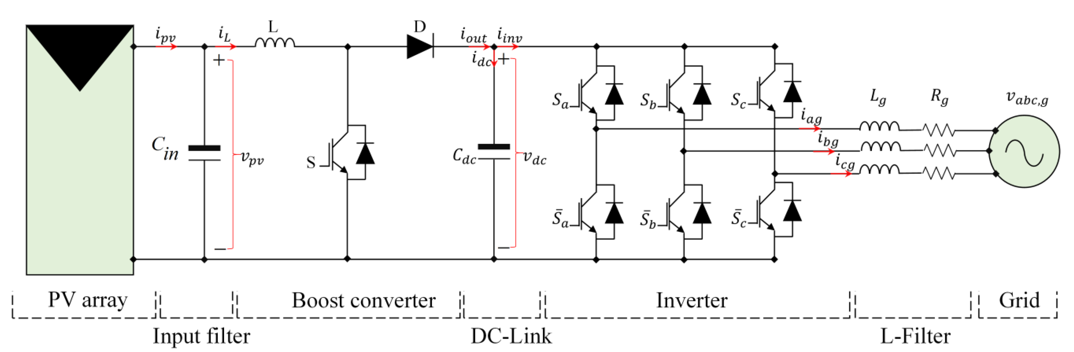
2. Overall System Configuration
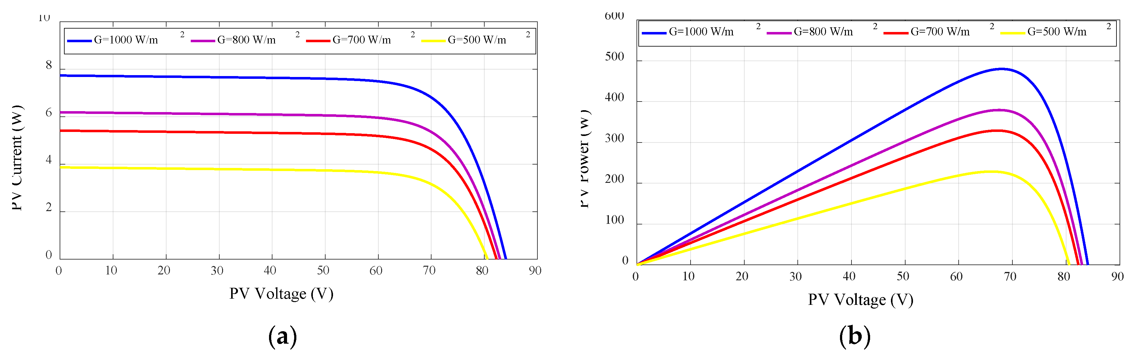
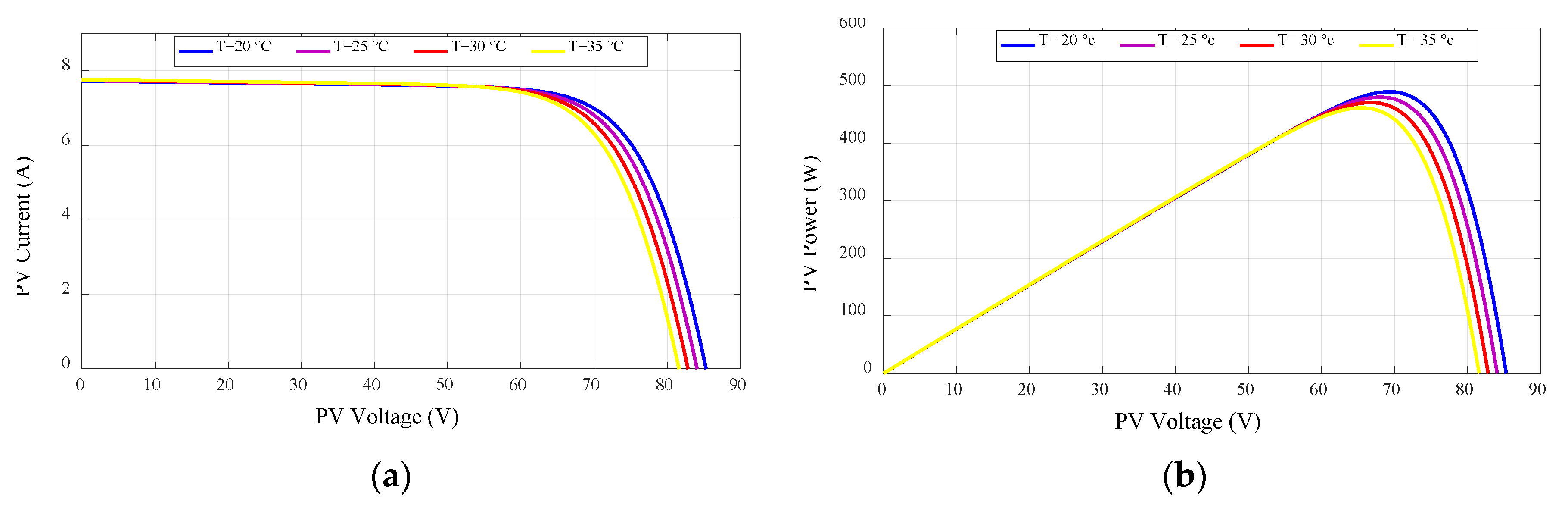
2.1. PV Array Model
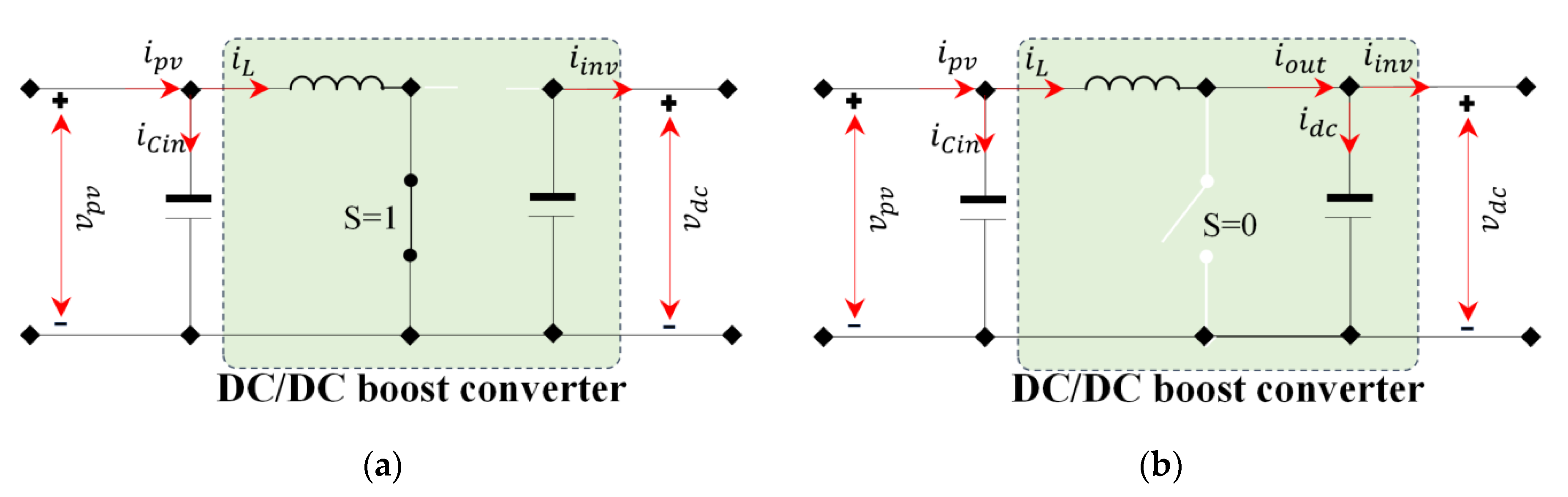
2.2. Boost Converter Modeling
2.3. Inverter Model
3. Proposed Control Scheme
- VO-MPPT based on ISMC, to enhance the PV energy conversion efficiency under any irradiation changes.
- DC-Link voltage controller based on ISMC, to maintain the DC-Link voltage close to its reference under any irradiation changes.
- VOC based on the modified ISMC and SVM, to control the injection of the produced PV power into the grid.
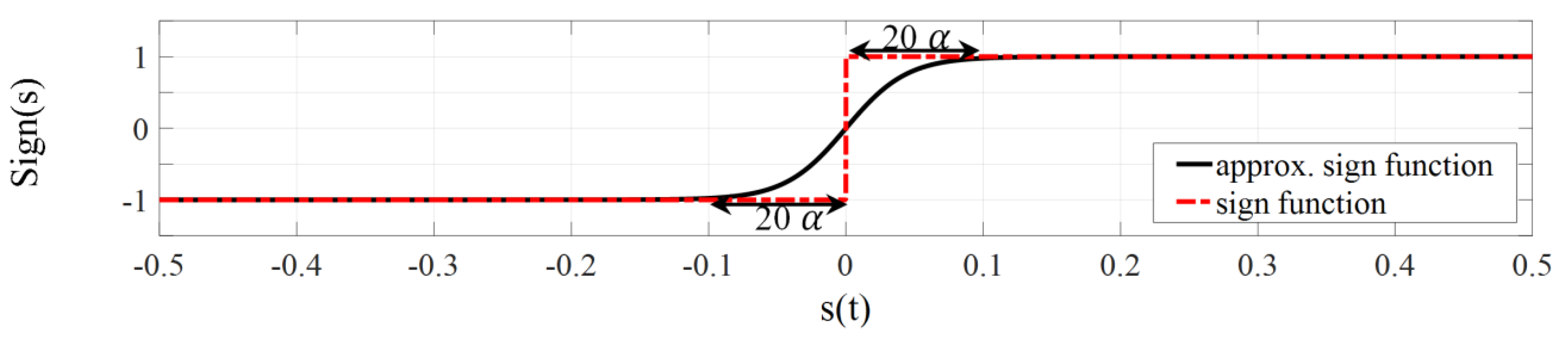
3.1. ISMC Theory
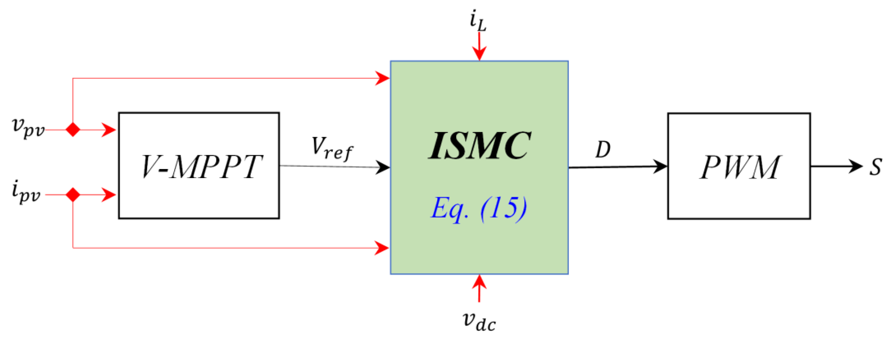
3.2. MPPT Control
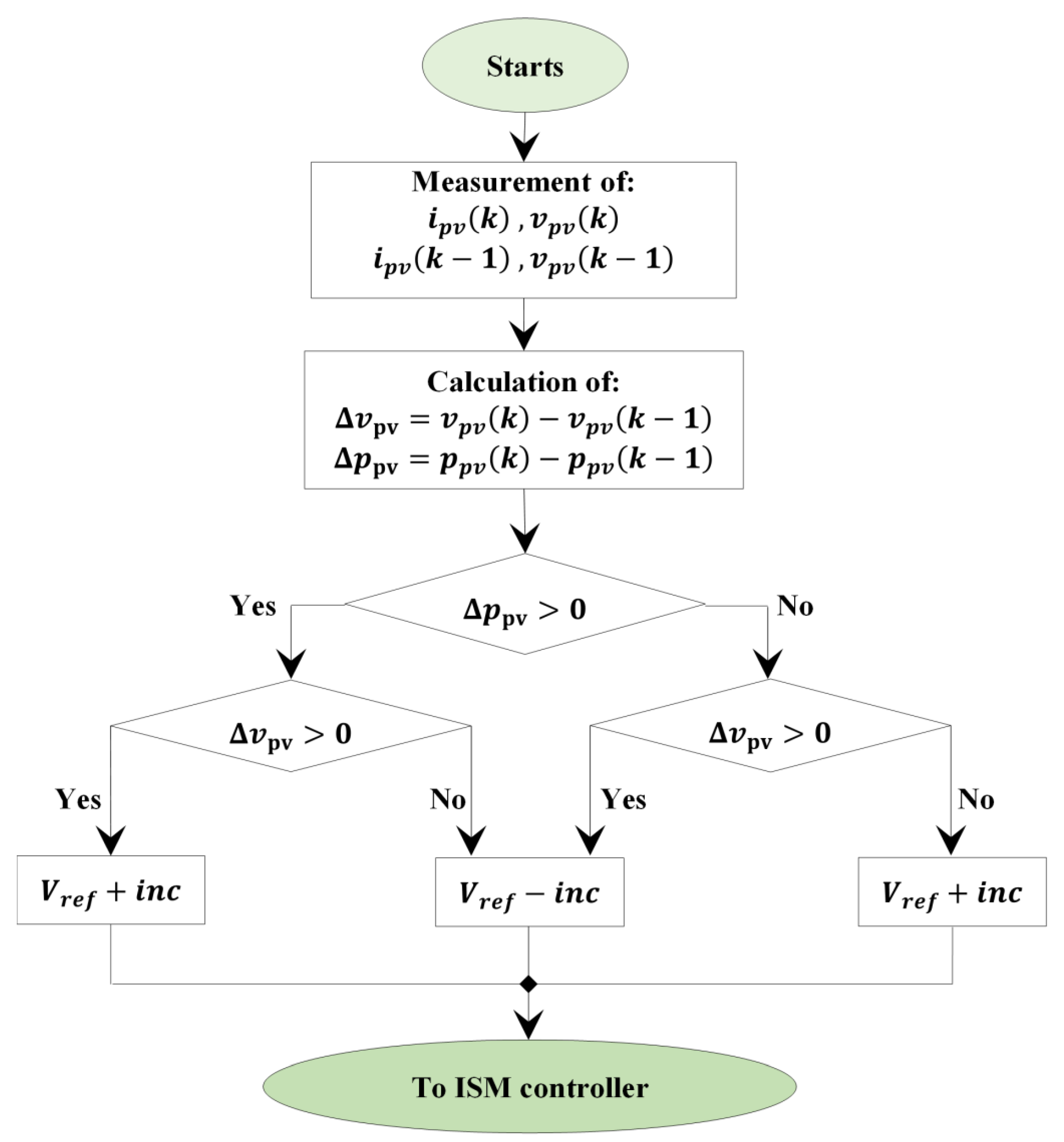
3.2.1. P&O-Based V-MPPT
3.2.2. ISM Controller Design
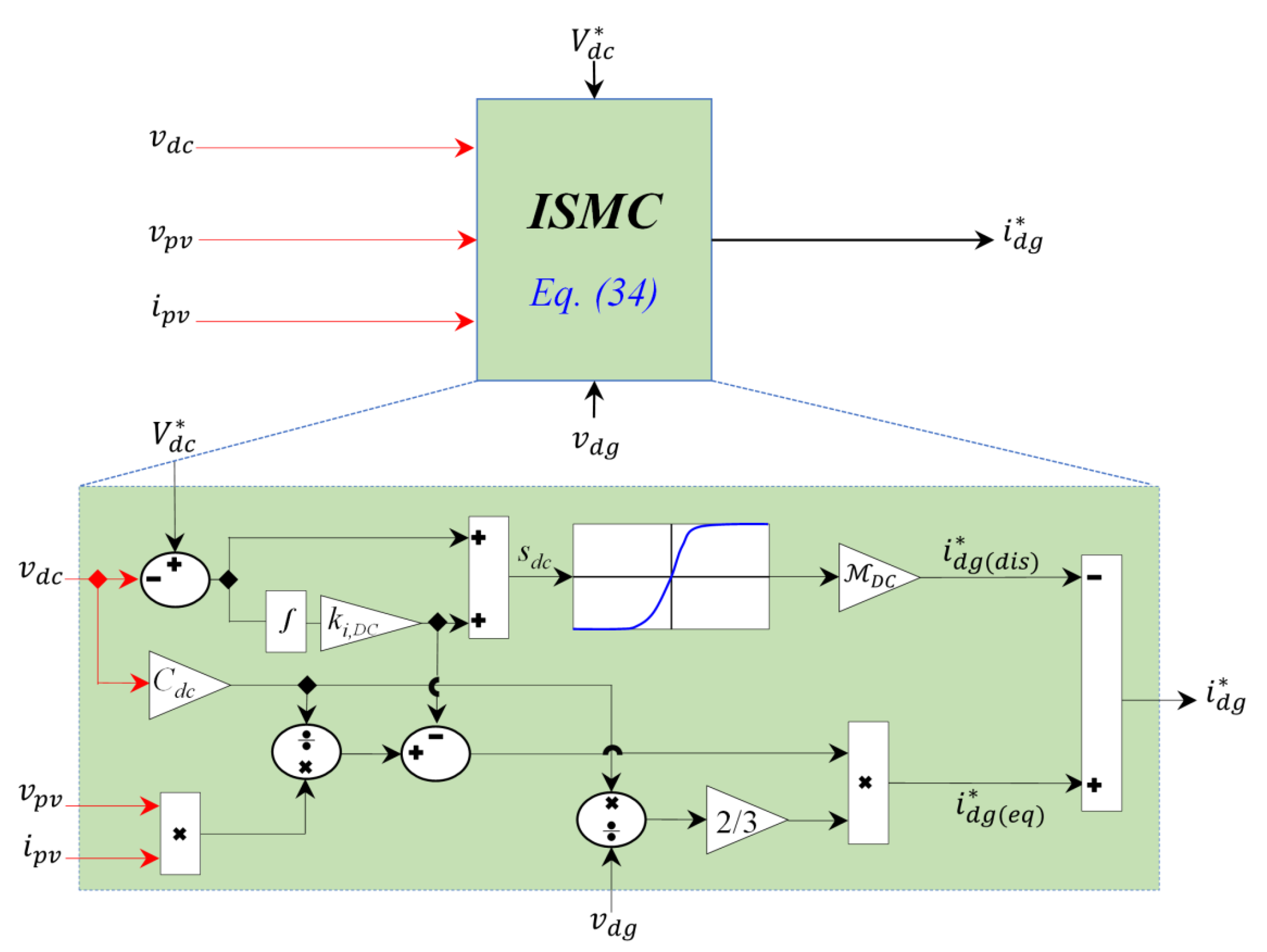
3.3. Design of DC-Link Voltage Controller
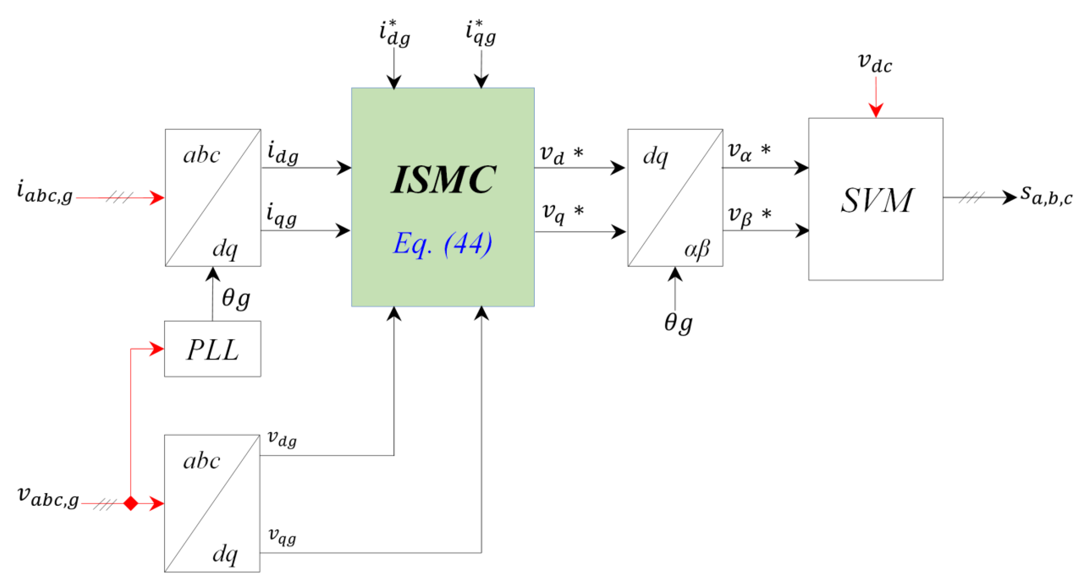
3.4. VOC Based ISMC
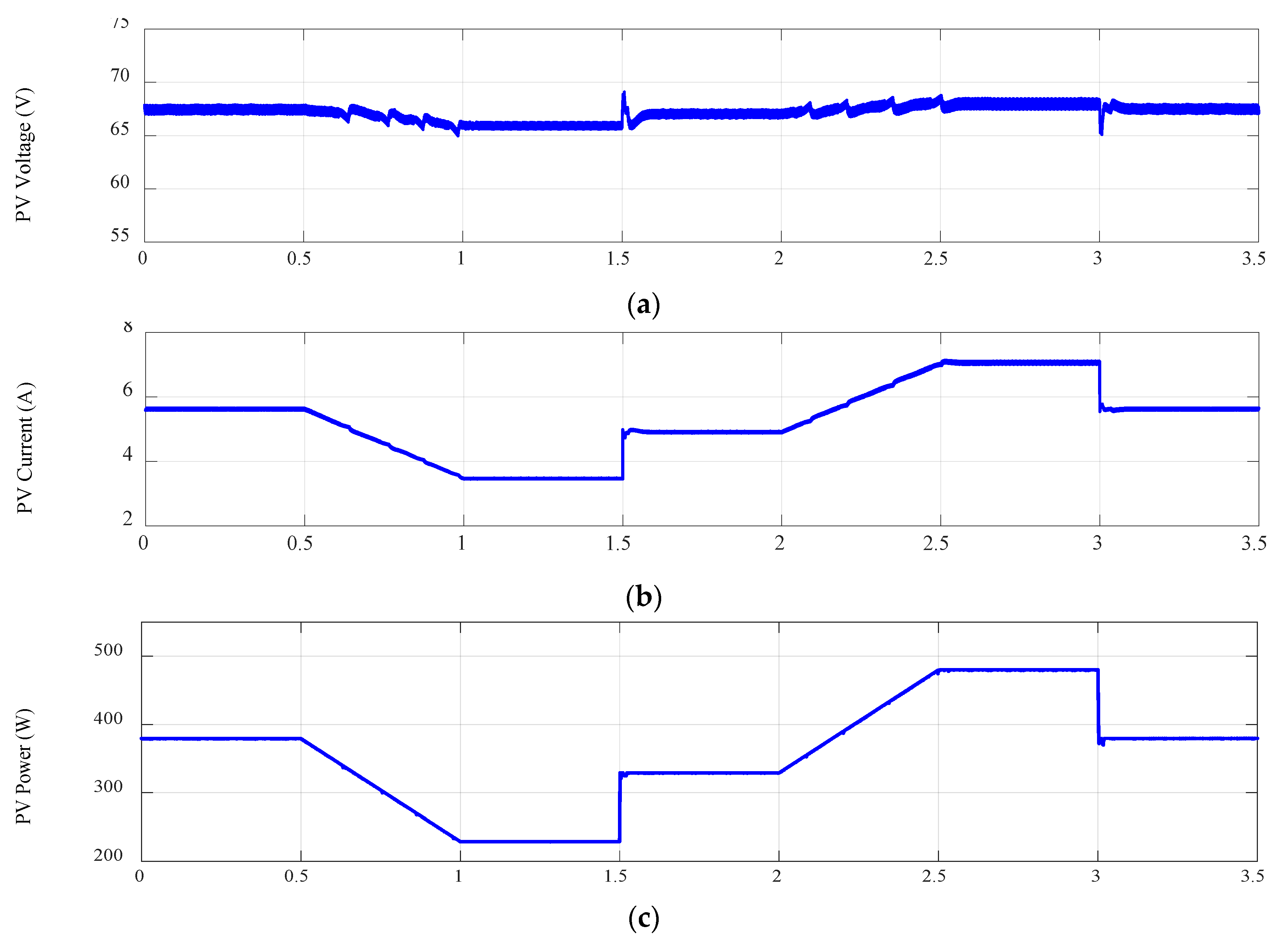
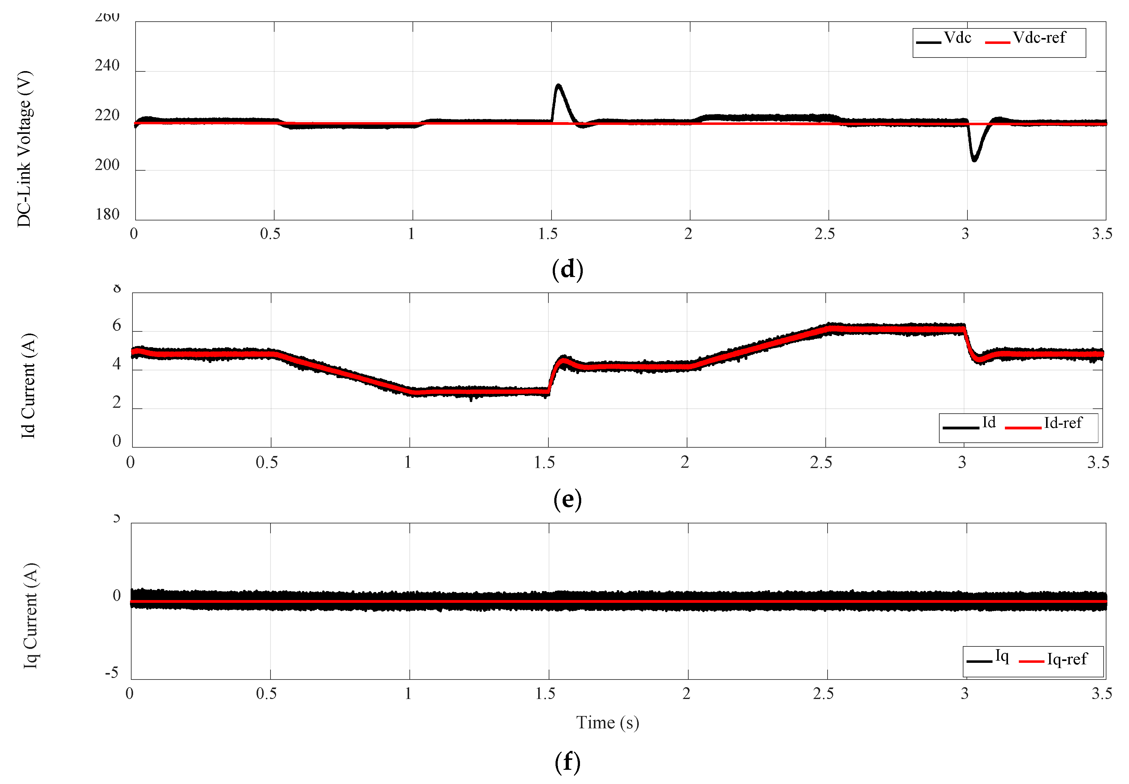
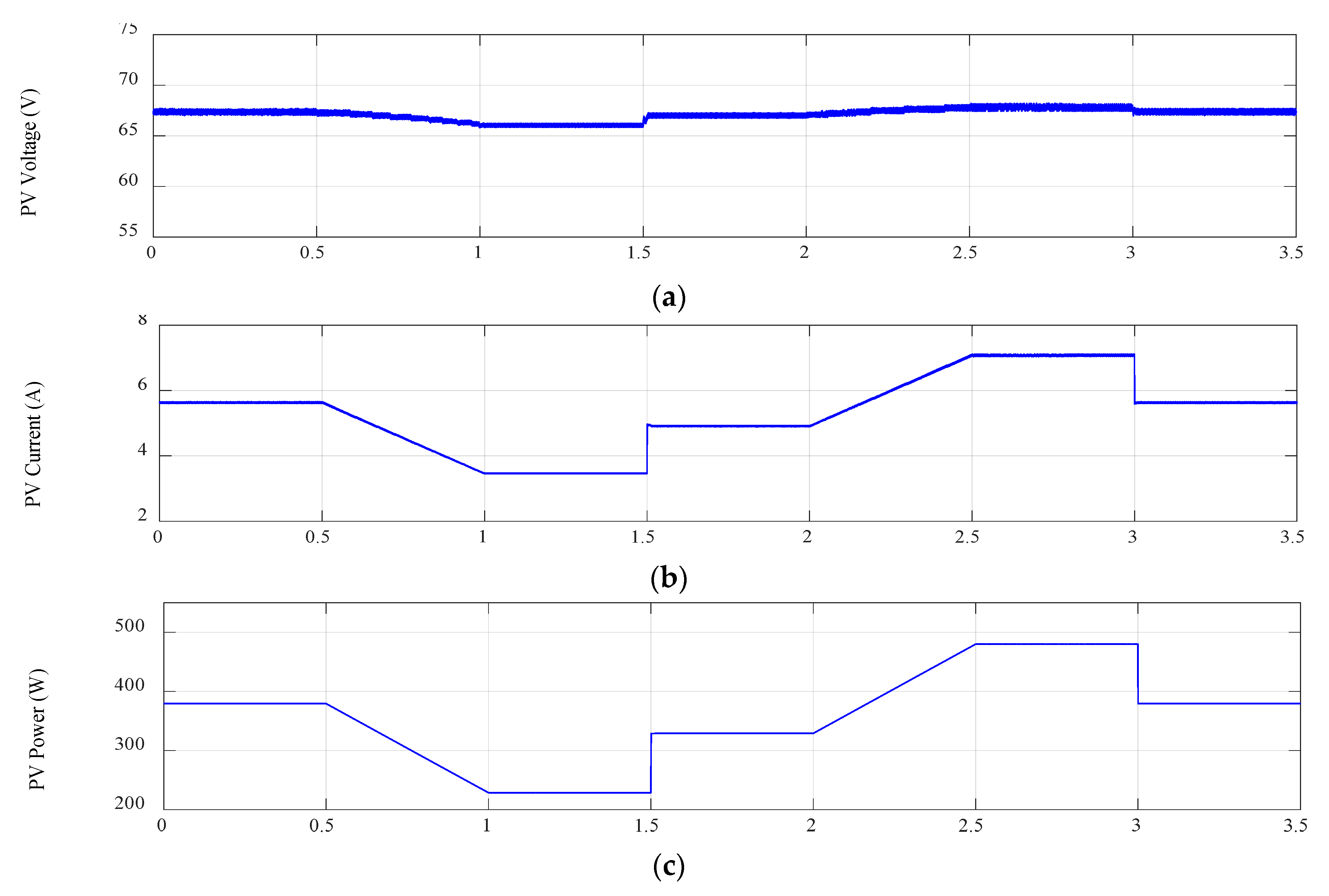
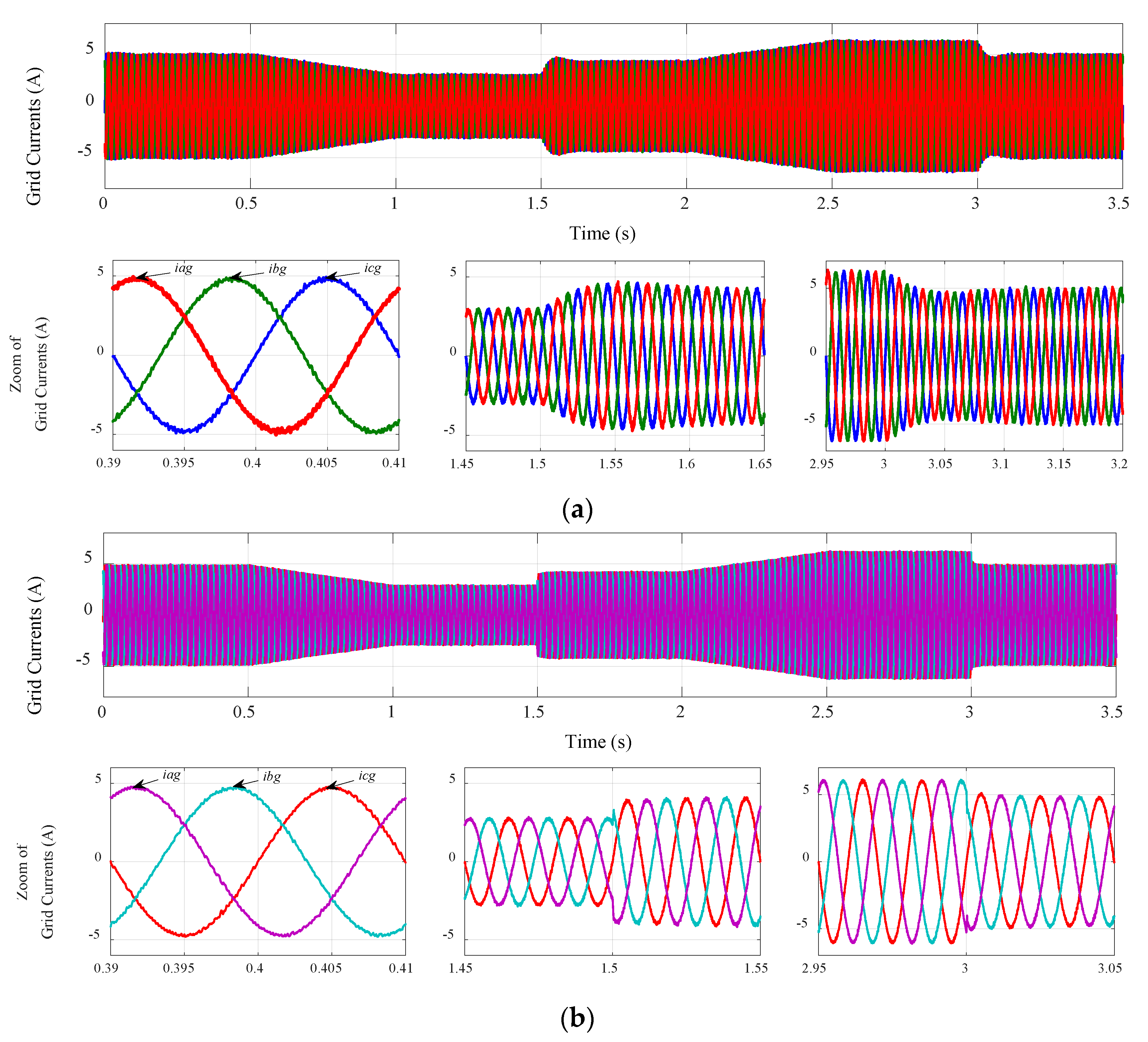
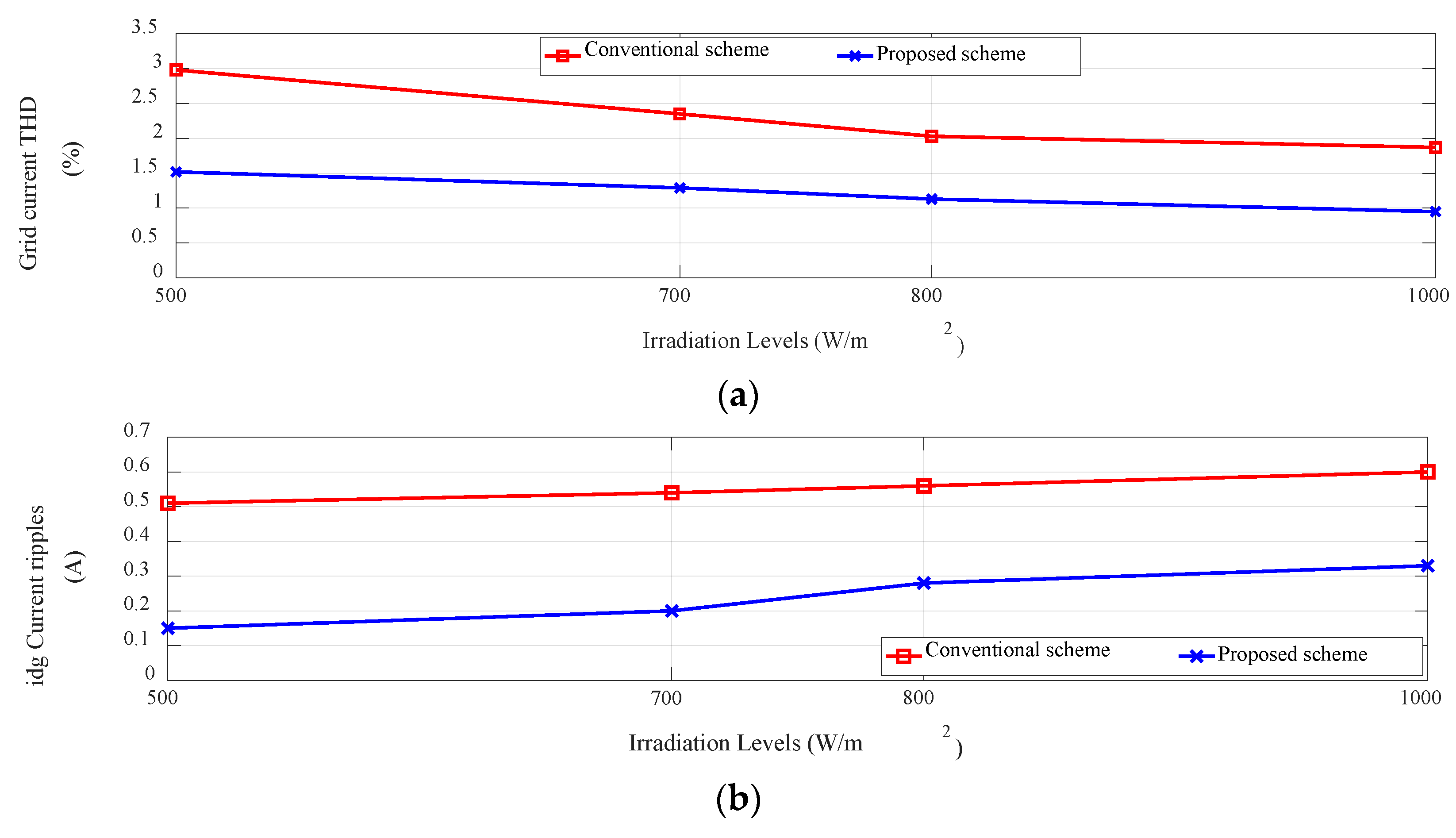
4. Simulation Results and Discussion
5. Conclusions
Author Contributions
Funding
Conflicts of Interest
Appendix A

| GPV | Nominal Values |
| Open circuit voltage | 42.1 [V] |
| Optimum operating voltage | 33.7 [V] |
| Short circuit current | 3.87 [A] |
| Optimum operating current | 3.56 [A] |
| Maximum power | 120 [W] |
| Number of cells connected in series | 72 |
| Number of cells connected in parallel | 1 |
| Number of panels connected in series | 2 |
| Number of panels connected in parallel | 2 |
| Boost converter | Values |
| Inductance | 1 [mH] |
| Input capacitor | 470 [µF] |
| output capacitor | 200 [µF] |
| Electrical parameters of grid-tied | Values |
| Output filter inductance | 10 [mH] |
| Line resistance | 0.1 [Ω] |
| Nominal grid frequency | 50 [Hz] |
| Nominal line voltage of the 3-phase grid | 100 [V] |
| Simulation parameters | Values |
| V-MPPT sampling frequency | 1 [kHz] |
| PWM switching frequency | 5 [kHz] |
| SVM switching frequency | 25 [kHz] |
References
- Dincer, F. The analysis on photovoltaic electricity generation status, potential and policies of the leading countries in solar energy. Renew. Sustain. Energy Rev. 2011, 15, 713–720. [Google Scholar] [CrossRef]
- Shayestehfard, A.; Mekhilef, S.; Mokhlis, H. IZDPWM based feed forward controller for grid connected inverters under unbalanced and distorted conditions. IEEE Trans. Ind. Electron. 2017, 64, 14–21. [Google Scholar] [CrossRef]
- Xiao, W.; Edwin, F.F.; Spagnuolo, G.; Jatskevich, J. Efficient approaches for modeling and simulating photovoltaic power systems. IEEE J. Photovolt. 2013, 3, 500–508. [Google Scholar] [CrossRef]
- Kanaan, H.; Caron, M.; Al-Haddad, K. Design and implementation of a two-stage grid-connected high efficiency power load emulator. IEEE Trans. Power Electron. 2014, 29, 3997–4006. [Google Scholar] [CrossRef]
- Debnath, D.; Chatterjee, K. Two-stage solar photovoltaic-based stand-alone scheme having battery as energy storage element for rural deployment. IEEE Trans. Ind. Electron. 2015, 62, 4148–4157. [Google Scholar] [CrossRef]
- Femia, N.; Petrone, G.; Spagnuolo, G.; Vitelli, M. Power Electronics and Control Techniques for Maximum Energy Harvesting in Photovoltaic Systems; CRC Press: Boca Raton, FL, USA, 2012. [Google Scholar]
- Ahmed, J.; Salam, Z. An improved perturb and observe (P&O) maximum power point tracktwotwing (MPPT) algorithm for higher efficiency. Appl. Energy 2015, 150, 97–108. [Google Scholar]
- De Brito, M.A.G.; Galotto, L.; Sampaio, L.P.; Melo, G.D.A.; Canesin, C.A. Evaluation of the main MPPT techniques for photovoltaic applications. IEEE Trans. Ind. Electron. 2013, 60, 1156–1167. [Google Scholar] [CrossRef]
- Safari, A.; Mekhilef, S. Simulation and hardware implementation of incremental conductance MPPT with direct control method using cuk converter. IEEE Trans. Ind. Electron. 2011, 58, 1154–1161. [Google Scholar] [CrossRef]
- Belkaid, A.; Colak, I.; Isik, O. Photovoltaic maximum power point tracking under fast varying of solar radiation. Appl. Energy 2016, 179, 523–530. [Google Scholar] [CrossRef]
- Rizzo, S.A.; Scelba, G. ANN based MPPT method for rapidly variable shading conditions. Appl. Energy 2013, 145, 124–132. [Google Scholar] [CrossRef]
- Karatepe, E.; Hiyama, T. Artificial neural network-polar coordinated fuzzy controller based maximum power point tracking control under partially shaded conditions. IET Renew. Power Gener. 2009, 3, 239–253. [Google Scholar]
- Zainuri, M.A.A.M.; Radzi, M.A.M.; Soh, A.C.; Abd Rahim, N. Development of adaptive perturb and observe-fuzzy control maximum power point tracking for photovoltaic boost dc–dc converter. IET Renew. Power Gener. 2014, 8, 183–194. [Google Scholar] [CrossRef]
- Bendib, B.; Belmili, H.; Krim, F. A survey of the most used MPPT methods: Conventional and advanced algorithms applied for photovoltaic systems. Renew. Sustain. Energy Rev. 2015, 45, 637–648. [Google Scholar] [CrossRef]
- Talbi, B.; Krim, F.; Rekioua, T.; Laib, A.; Feroura, H. Design and hardware validation of modified P&O algorithm by fuzzy logic approach based on model predictive control for MPPT of PV systems. J. Renew. Sustain. Energy 2017, 9, 043503. [Google Scholar]
- Shaiek, Y.; Smida, M.B.; Sakly, A.; Mimouni, M.F. Comparison between conventional methods and GA approach for maximum power point tracking of shaded solar PV generators. Sol. Energy 2013, 90, 107–122. [Google Scholar] [CrossRef]
- Ishaque, K.; Salam, Z.; Amjad, M.; Mekhilef, S. An improved particle swarm optimization (PSO)–based MPPT for PV with reduced steady-state oscillation. IEEE Trans. Power Electron. 2012, 27, 3627–3638. [Google Scholar] [CrossRef]
- Mohanty, S.; Subudhi, B.; Ray, P.K. A new MPPT design using grey wolf optimization technique for photovoltaic system under partial shading conditions. IEEE Trans. Sustain. Energy 2016, 7, 181–188. [Google Scholar] [CrossRef]
- Bianconi, E.; Calvente, J.; Giral, R.; Mamarelis, E.; Petrone, G.; Ramos-Paja, C.A.; Spagnuolo, G.; Vitelli, M. A fast current-based MPPT technique employing sliding mode control. IEEE Trans. Ind. Electron. 2013, 60, 1168–1178. [Google Scholar] [CrossRef]
- Kakosimos, P.E.; Kladas, A.G.; Manias, S.N. Fast photovoltaic-system voltage-or current- oriented MPPT employing a predictive digital current-controlled converter. IEEE Trans. Ind. Electron. 2013, 60, 5673–5685. [Google Scholar] [CrossRef]
- Elgendy, M.A.; Zahawi, B.; Atkinson, D.J. Assessment of perturb and observe MPPT algorithm implementation techniques for PV pumping applications. IEEE Trans. Sustain. Energy 2012, 3, 21–33. [Google Scholar] [CrossRef]
- Pradhan, R.; Subudhi, B. Double integral sliding mode MPPT control of a photovoltaic system. IEEE Trans. Cont. Syst. Technol. 2016, 24, 285–292. [Google Scholar] [CrossRef]
- Farhat, M.; Barambones, O.; Sbita, L. A new maximum power point method based on a sliding mode approach for solar energy harvesting. Appl. Energy 2017, 185, 1185–1198. [Google Scholar] [CrossRef]
- Talbi, B.; Krim, F.; Rekioua, T.; Mekhilef, S.; Laib, A.; Belaout, A. A high-performance control scheme for photovoltaic pumping system under sudden irradiance and load changes. Sol. Energy 2018, 159, 353–368. [Google Scholar] [CrossRef]
- Menadi, A.; Abdeddaim, S.; Ghamri, A.; Betka, A. Implementation of fuzzy-sliding mode based control of a grid connected photovoltaic system. ISA Trans. 2015, 58, 586–594. [Google Scholar] [CrossRef] [PubMed]
- Vitorino, M.A.; de Rossiter, C.M.B.; Jacobina, C.B.; Lima, A.M.N. An effective induction motor control for photovoltaic pumping. IEEE Trans. Ind. Electron. 2011, 58, 1162–1170. [Google Scholar] [CrossRef]
- Achour, A.; Rekioua, D.; Mohammedi, A.; Mokrani, Z.; Rekioua, T.; Bacha, S. Application of direct torque control to a photovoltaic pumping system with sliding-mode control optimization. Electr. Power Compon. Syst. 2016, 44, 172–184. [Google Scholar] [CrossRef]
- Hu, J.; Zhu, Z.Q. Investigation on switching patterns of direct power control strategies for grid-connected DC–AC converters based on power variation rates. IEEE Trans. Power Electron. 2011, 26, 3582–3598. [Google Scholar] [CrossRef]
- Malinowski, M.; Kazmierkowski, M.P.; Hansen, S.; Blaabjerg, F.; Marques, G.D. Virtual-flux-based direct power control of three-phase PWM rectifiers. IEEE Trans. Ind. Appl. 2001, 37, 1019–1027. [Google Scholar] [CrossRef]
- Jain, C.; Singh, B. A three-phase grid tied SPV system with adaptive DC link voltage for CPI voltage variations. IEEE Trans. Sustain. Energy 2016, 7, 337–344. [Google Scholar] [CrossRef]
- Rodriguez, J.; Pontt, J.; Silva, C.A.; Correa, P.; Lezana, P.; Cortés, P.; Ammann, U. Predictive current control of a voltage source inverter. IEEE Trans. Ind. Electron. 2007, 54, 495–503. [Google Scholar] [CrossRef]
- Teodorescu, R.; Liserre, M.; Rodriguez, P. Grid Converters for Photovoltaic and Wind Power Systems; John Wiley & Sons: Hoboken, NJ, USA, 2011. [Google Scholar]
- Utkin, V.I. Sliding mode control design principles and applications to electric drives. IEEE Trans. Ind. Electron. 1993, 40, 23–36. [Google Scholar] [CrossRef]
- Edwards, C.; Spurgeon, S. Sliding Mode Control: Theory and Applications; CRC Press: Boca Raton, FL, USA, 1998. [Google Scholar]
- Tan, S.C.; Lai, Y.M.; Tse, C.K. Sliding Mode Control of Switching Power Converters: Techniques and Implementation; CRC Press: Boca Raton, FL, USA, 2011. [Google Scholar]
- Sebaaly, F.; Vahedi, H.; Kanaan, H.Y.; Moubayed, N.; Al-Haddad, K. Sliding mode fixed frequency current controller design for grid-connected NPC inverter. IEEE J. Emerg. Slect. Top. Power Electron. 2016, 4, 1397–1405. [Google Scholar] [CrossRef]
- Van Dijk, E.; Spruijt, J.N.; O’sullivan, D.M.; Klaassens, J.B. PWM-switch modeling of DC-DC converters. IEEE Trans. Power Electron. 1995, 10, 659–665. [Google Scholar] [CrossRef]
- Utkin, V.; Guldner, J.; Shi, J. Sliding Mode Control in Electro-Mechanical Systems; CRC Press: Boca Raton, FL, USA, 2009. [Google Scholar]
- Hamayun, M.T.; Edwards, C.; Alwi, H. Fault Tolerant Control Schemes Using Integral Sliding Modes; Springer International Publishing: Berlin, Germany, 2016. [Google Scholar]
- Yaramasu, V.; Wu, B.; Chen, J. Model-predictive control of grid-tied four-level diode-clamped inverters for high-power wind energy conversion systems. IEEE Trans. Power Electron. 2014, 29, 2861–2873. [Google Scholar] [CrossRef]


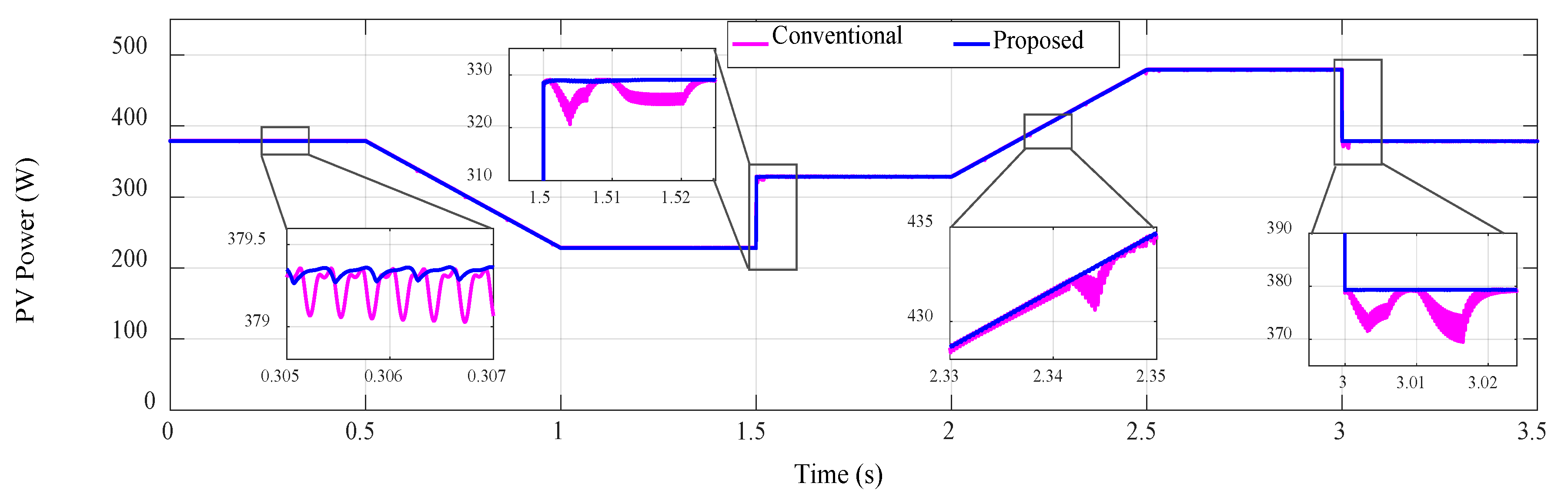
| MPPT Technique | Step Change in Irradiation 500→700 W/m² | Step Change in Irradiation 1000→800 W/m² | Linear Changes in Irradiation 800→500 W/m² and 700→1000 W/m² | ||
|---|---|---|---|---|---|
| Power Oscillation (W) | Response Time (s) | Power Oscillation (W) | Response Time (s) | Tracking Accuracy | |
| Conventional VO-MPPT | 0.17 | 0.022 | 0.23 | 0.02 | low |
| Proposed VO-MPPT | Less than 0.03 | 0.0085 | 0.051 | 0.0061 | Very good |
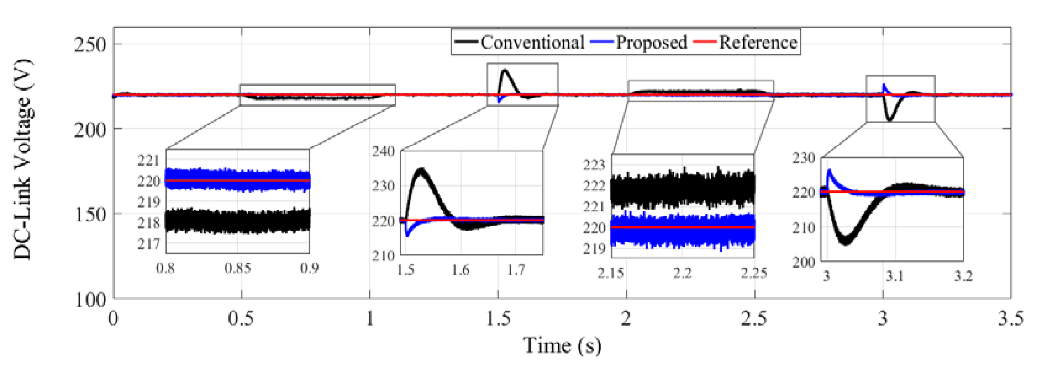
| Control Scheme | Linear Change in Irradiance 800→500 W/m² | Step Change in Irradiance 500→700 W/m² | Linear Change in Irradiance 700→1000 W/m² | Step Change in Irradiance 1000→800 W/m² | ||
|---|---|---|---|---|---|---|
| Static Error Average (%) | Overshoot (%) | Settling Time (s) | Static error Average (%) | Overshoot (%) | Settling Time (s) | |
| Conventional PI | 1.512 | 6.95 | 0.175 | 1.478 | 7.47 | 0.179 |
| Proposed scheme | 0.051 | 2.2 | 0.035 | 0.057 | 2.98 | 0.08 |
© 2018 by the authors. Licensee MDPI, Basel, Switzerland. This article is an open access article distributed under the terms and conditions of the Creative Commons Attribution (CC BY) license (http://creativecommons.org/licenses/by/4.0/).
Share and Cite
Kihal, A.; Krim, F.; Talbi, B.; Laib, A.; Sahli, A. A Robust Control of Two-Stage Grid-Tied PV Systems Employing Integral Sliding Mode Theory. Energies 2018, 11, 2791. https://doi.org/10.3390/en11102791
Kihal A, Krim F, Talbi B, Laib A, Sahli A. A Robust Control of Two-Stage Grid-Tied PV Systems Employing Integral Sliding Mode Theory. Energies. 2018; 11(10):2791. https://doi.org/10.3390/en11102791
Chicago/Turabian StyleKihal, Abbes, Fateh Krim, Billel Talbi, Abdelbaset Laib, and Abdeslem Sahli. 2018. "A Robust Control of Two-Stage Grid-Tied PV Systems Employing Integral Sliding Mode Theory" Energies 11, no. 10: 2791. https://doi.org/10.3390/en11102791
APA StyleKihal, A., Krim, F., Talbi, B., Laib, A., & Sahli, A. (2018). A Robust Control of Two-Stage Grid-Tied PV Systems Employing Integral Sliding Mode Theory. Energies, 11(10), 2791. https://doi.org/10.3390/en11102791