Dual Frequency Regulation in Pumping Mode in a Wind–Hydro Isolated System
by
 , and
, and
José Ignacio Sarasúa
1, 
Guillermo Martínez-Lucas
1,
Carlos A. Platero
2 and
and
José Ángel Sánchez-Fernández
1,* 1
Department of Hydraulic, Energy and Environmental Engineering, Universidad Politécnica de Madrid, C/Profesor Aranguren 3, 28040 Madrid, Spain
2
Department of Electrical Engineering, E.T.S.I. Industriales, Universidad Politécnica de Madrid, C/José Gutierrez Abascal 2, 28006 Madrid, Spain
*
Author to whom correspondence should be addressed.
Energies 2018, 11(11), 2865; https://doi.org/10.3390/en11112865
Submission received: 4 October 2018
/
Revised: 19 October 2018
/
Accepted: 20 October 2018
/
Published: 23 October 2018
(This article belongs to the Special Issue 10 Years Energies - Horizon 2028)
Abstract
:Frequency control is one of the most critical tasks in isolated power systems, especially in high renewable penetration scenarios. This paper presents a new hydropower pumped-storage dual control strategy that combines variable-speed-driven pumps and fixed-speed-driven pumps. A possible case for implementation of such a control scheme is described based on El Hierro Island’s power system. This isolated power system consists of a hybrid wind pumped-storage hydropower plant and diesel generators. The pumped-storage power plant is divided into a hydropower plant equipped with four Pelton turbines and a pump station equipped with both fixed- and variable-speed pumps. According to the proposed control scheme, frequency regulation will be provided by a dual controller: a continuous controller for the variable-speed pumps and a discrete controller for the fixed-speed pumps. The Pelton units, which operate as synchronous condensers, also supply the power system inertia. Therefore, diesel units may be disconnected, decreasing generation costs and greenhouse gas emissions. Owing to the combination of both controllers and the inertia of the Pelton units, an acceptable frequency regulation can be achieved. This technique has been validated through computer simulations.
1. Introduction
One of the known methods of increasing renewable energy integration in power systems is by means of pumped-storage hydropower plants (PSHPs) [1]. In case of large interconnected power systems, their role mainly involves leveling the daily or weekly power demand curve [2,3,4]. Traditionally, fixed-speed PSHPs contribute continuously to frequency regulation in turbine operation mode and to starting and stopping units in pump operation mode [5]. However, due to advances in power electronics, variable-speed PSHPs can nowadays contribute continuously to frequency regulation in both modes [5,6,7].
Frequency regulation is the most expensive ancillary service [8]. For island power systems, this is more challenging than in large interconnected power systems due to the lower inertia inherent to island power systems [9]. For this reason, specific grid codes for island power systems have been developed [10]. In these systems, there are several contributions that enhance turbine mode operation of PSHPs [11,12,13,14].
Variable-speed pumping can get remarkable energy savings [15]. In fact, there are several studies on the economic gains attainable through variable-speed operation of PSHPs [16,17]. In addition, the contribution of variable-speed PSHPs to frequency regulation has been explored. In Reference [18], a PSHP equipped with doubly fed adjustable-speed units was modeled in both operation modes—generating and pumping—connected to a high-inertia power system. Simulations were compared with real data from Okawachi Pumped-Storage Power Plant. Results showed that the converter response was virtually instantaneous compared to rotor speed deviations or wicket gate movements so that the response to the power command signal was improved. These results were confirmed in Reference [19], where the dynamic response of a PSHP providing primary regulation in pumping mode was simulated. In Reference [20], an isolated power system that included a wind farm, a thermal power plant, and a variable-speed PSHP was modeled. Simulation results confirmed that variable-speed units operating in pumping mode reduced frequency deviations caused by wind speed fluctuations. However, frequency converters supplying the rotor of variable-speed machines induced harmonics on active power. In Reference [21], the main part of the power system on Faroe Islands was modeled, including a diesel group, a conventional hydropower plant, a wind farm and a PSHP. Several control strategies for the pumped-storage power plant in pumping mode were studied to include their contribution to primary regulation. Simulation results demonstrated that variable-speed units in pumping mode in this isolated power system could compensate fluctuations in the power generated by the wind farm.
El Hierro is an island in the Canary island archipelago. Historically, electric generation has been based on diesel generators. However, the island aims to become entirely free from carbon dioxide emissions [22]. In order to contribute to the achievement of this objective, a hybrid wind pumped-storage hydropower plant (W-PSHP) was committed in June 2014 to minimize utilization of fossil fuels [23]. The PSHP is divided into a hydropower plant equipped with four Pelton turbines and a pump station. As mentioned above, in the case of small autonomous power systems with reduced short-circuit power, using variable-speed pumps (VSPs)—and consequently frequency converters—may cause severe power quality problems due to converter-caused harmonics. As fixed-speed pumps (FSPs) do not produce harmonics, the pump station is equipped with both FSPs and VSPs.
The most challenging situation for this system takes place when there is high wind power production and not enough power demand to absorb the total amount of wind energy. Therefore, the pump station must consume the difference between the wind power supplied and the power consumed. Usually in this scenario, some diesel units are connected so they can provide primary reserve and inertia, both enough for maintaining frequency under safe values. This paper presents a new PSHP control strategy that combines variable-speed-driven pumps and fixed-speed-driven pumps in the described scenario. Here, frequency regulation is only provided by a dual controller: a continuous speed regulator for the VSPs and a discrete controller for the FSPs. The inertia is supplied by Pelton units, which operate as synchronous condensers [24]. In this manner, diesel units may be disconnected, decreasing generation costs and greenhouse gas emissions. Owing to the combination of both controllers and the inertia of the Pelton units, an acceptable frequency regulation can be achieved. This technique has been validated through computer simulations.
The remaining paper is organized as follows: Section 2 presents the main characteristics of the power system. Section 3 describes the simulation model used. Section 4 describes the proposed control of the pump station. Section 5 presents and discusses the simulations made. Finally, Section 6 draws the conclusions.
2. Wind–Hydro Power Plant and Power System Description
El Hierro is an island belonging to the Canary Islands archipelago, which was declared as a biosphere reserve by the UNESCO. The island aims to become 100% free of greenhouse gas emissions [22]. The maximum peak demand in 2016 was 7.7 MW, whereas the minimum was approximately 4 MW [25]. The electrical capacity of the island is 37.8 MW, mainly distributed by diesel generators of 15 MW and a W-PSHP of 22.8 MW. Table 1 lists the energy supplied by the different technologies during 2016.
In Figure 1, the simplified scheme of the W-PSHP is shown, describing the water and energy flow according to the operation mode of the turbine and the pump. The wind farm, at a power rate of 11.5 MW, is equipped with five variable-speed wind turbines (VSWTs) ENERCON-E70, while the four Pelton turbines provide the remaining power of 4 × 2.8 MW [23]. The PSHP includes a pump station that is able to consume 6 MW. The pump station is equipped with 6 × 0.5 MW FSPs and 2 × 1.5 MW VSPs.
As stated above, in this paper, a new dual frequency control provided only by the pumping station is proposed when there is high wind power production. Diesel units are not connected to the grid. The four generators driven by the Pelton turbines, as shown in Figure 2, operate as synchronous condensers and not in no-flow mode [24]. Therefore, they provide voltage regulation and inertia. Figure 2 shows a simplified one-line diagram of El Hierro power system in this scenario.
3. Model Description
A dynamic model of the power system has been developed in Matlab Simulink to obtain the system dynamic response and check the effectiveness of the new controller. The main elements of this model are the power system, the pump station, and VSWTs. Due to the reduced size of the power system, the power lines have not been modeled. All the parameters used in the model are presented in Appendix A.
3.1. Power System
The frequency deviation of the power system has been modeled by means of an aggregate inertial model [26]. This approximation has been experimentally validated in Reference [27] for the isolated system of Ireland’s power system. Equation (1) models frequency deviations produced by the imbalance between power generated by the wind turbines and the power consumed by the pump station and consumer loads. Demand sensitivity to frequency variations is included through Dnet [28].
As previously explained, the hydroelectric units are connected to the net as synchronous condensers. Therefore, system inertia, Tm, corresponds to the mechanical starting time of the Pelton units.
3.2. Pump Station
The frequency controller for the pump station will maintain frequency under safe conditions by means of varying electrical power consumed by VSPs and shutting off or starting FSP. Therefore, a proper model of the pumps and the pump station hydraulic circuit must be developed. In this way, the hydraulic phenomena associated with the start-up or disconnection of the pumps or variations in their rotational speed are taken into account.
3.2.1. Conduits
The hydraulic circuit between the head pond and the lower reservoir is composed of the penstock, manifold, eight pipes that join the manifold, and the pumps and pipes that connect each pump with the lower reservoir. The dynamics of these last pipes can be neglected because of their short length.
The pump station and hydropower plant both share the upper and lower reservoirs, but there are two different penstocks for each hydraulic circuit. Because of the length of the pump station penstock, a water elastic model is required for modeling its dynamic response. In this paper, a lumped parameters approach [29] has been used in order to convert mass and momentum conservation equations into ordinary differential expressions—Equations (2) and (3).
Tw represents the penstock water starting time, as defined in Equation (4):
Equations (2) and (3) can be represented as a series of Γ-shaped consecutive elements of length Le. The orientation and configuration of the elements are adapted according to the upstream and downstream boundary conditions of the pipe. In this case, upstream condition is the total flow pumped by all the groups, qp, and downstream condition is the water level in the higher reservoir, hhr. A scheme of the model can be seen in Figure 3.
The pipes from all pumps join in the manifold. It is assumed that the confluence of all pipes takes place in the same point. Therefore, the pressure in the end point of each pipe is the same, hm. Figure 4 shows a hydraulic scheme of the pump station.
Due to its short length, the pipes between the pumps and the manifold have been modeled assuming a rigid water column approach, including water inertia and head losses. When the pump i is connected, pipe dynamics is given in Equation (5). When the pump number i is not operating, qi is equal to zero, and the pressure upstream the corresponding pipe hp,i is equal to the manifold one, hm. Therefore, in this case, pressure is constant along the pipe.
Twp,i represents the water starting time of the pipe between the pump i and manifold, as defined in Equation (6):
The total flow in the lower point of the penstock, qp, is obtained from the sum of the flows from the eight pipes, qp,i, Equation (7):
The pressure downstream the pumps is obtained from the net head in the pumps, hni, and the water level in the lower reservoir, hlr (8):
3.2.2. Hydraulic Machines
As internal dynamics in the hydraulic machines is neglected [30], the flow, qp,i, in the pipes between the pumps and the manifold is considered equal to pumped flow by each pump, qi. The net head in each pump is calculated from Equation (9), and the mechanical power needed by the hydraulic machine to elevate the flow is obtained from Equation (10). Both expressions have been formulated through the two different pump operation curves—FSP and VSP—corresponding to their nominal rotational speed. Hydraulic similarity has been used to infer net head and mechanical power corresponding to other rotational speeds.
3.2.3. Electric Machines
Equation (11) is used to evaluate speed deviations of each electrical machine, np,i, as a function of the unbalance between the mechanical and the electrical torques. This expression is used for both FSP and VSP, varying the inertia constant Ji.
The electrical power consumed by the fixed-speed asynchronous machines is obtained using Equation (12):
Although the eight electrical machines are asynchronous, units 1 and 8 are equipped with a full converter. Therefore, they can modify the power consumed. In these units, a proportional-integral (PI) governor determines the electrical power absorbed from the grid. The VSP converter dynamics are much faster than the dynamics of other components of the model [18]. Therefore, the VSP converter dynamics are neglected and the power reference, pref,i, from the PI governor will be the same as the electrical power consumed by the motor, pe,i, in units 1 and 8.
3.3. Variable-Speed Wind Turbines
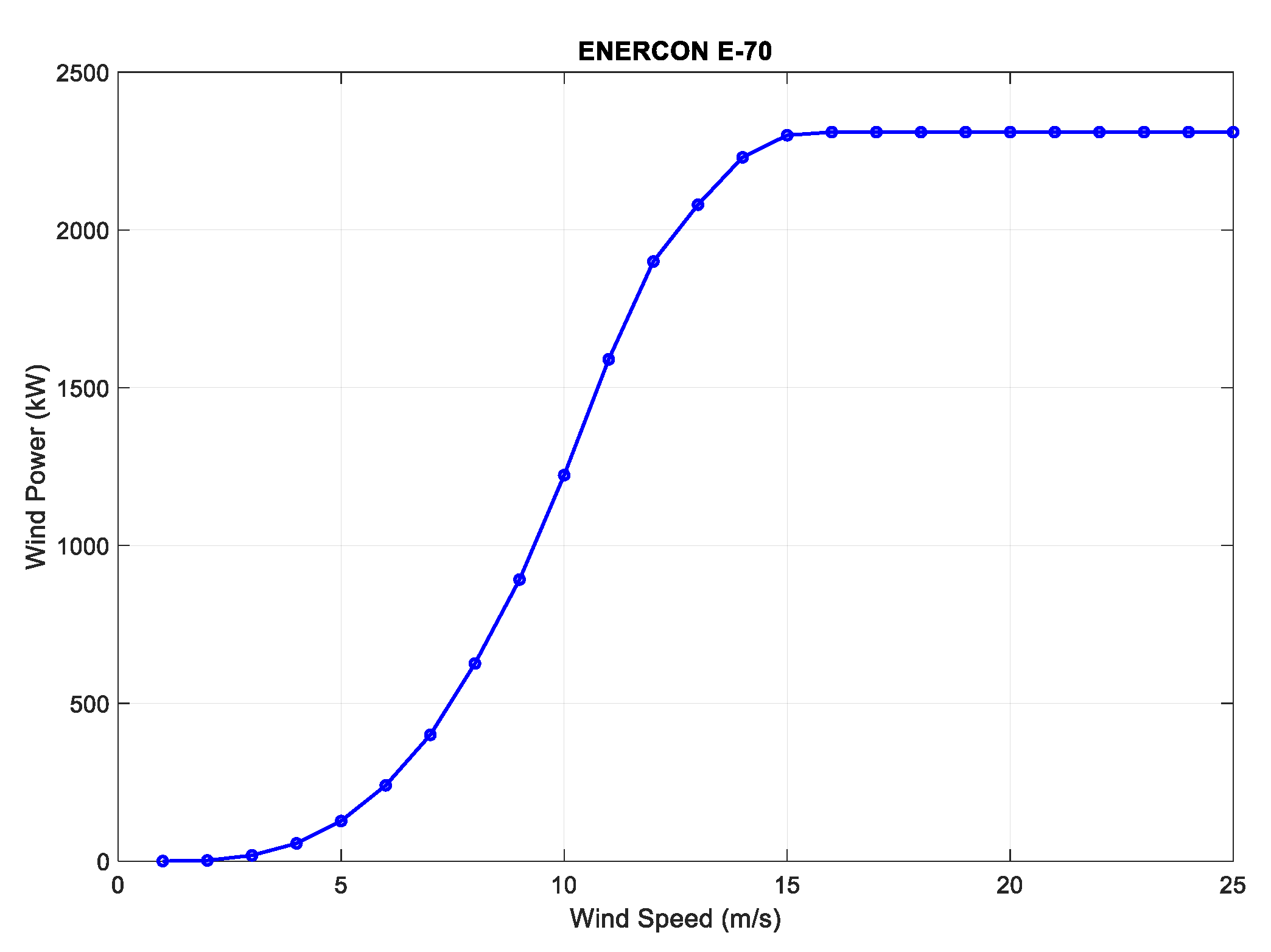
As described above, the wind farm is equipped with five VSWTs ENERCON E-70 (2.3 MW rated power). These VSWTs are designed for high average wind speeds, which are characteristic of Canary Islands [31]. This wind speed range corresponds to class I in the wind turbine generator classes (IEC/NVN) [32]. As these VSWTs do not provide frequency regulation, their blade pitch dynamics have not been taken into account. The power extracted from the wind has been modeled using the VSWT power curve provided by the manufacturer [32]. Figure 5 shows this curve.
The dynamics of VSWTs is introduced in the model through a transfer function, Equation (13), i.e., the first order delay. According to Reference [12], the time constant, Ti, has been obtained from an iterative process.
4. Pump Station Control System
In the scenario considered, VSWTs do not provide frequency regulation, Pelton units operate as synchronous condensers, and diesel units are disabled. Therefore, frequency regulation is only provided by the pump station. The power consumed by the two VSPs (Pumps 1 and 8) should be modified as well as the number of FSPs in operation (Pumps 2, 3, 4, 5, 6, and 7) to maintain the power system frequency, Figure 6.
4.1. Variable-Speed Pump Control
Frequency disturbances will initially be mitigated by means of a frequency controller that modifies the power consumed by the pumps. Frequency deviations are corrected through an adjustment of the power reference tracked by the converter (see Figure 6) according to the PI control, Equation (14):
Power converters, according to the modification in power reference, change electric power demanded by VSPs, thus reducing frequency deviation. Consequently, according to Equation (11), rotor speed, np, and mechanical power from the hydraulic machines, pp, will adapt to the new electrical power.
The normal operation power range of each VSP is delimited by the maximum (1.5 MW) and minimum allowable power (900 kW). Therefore, the regulating capacity is limited to 2 × (1.5 − 0.9) = 1.2 MW. For this reason, an anti-windup scheme has been introduced in the controller. These power limits are related to the maximum rotational speed Nbmax (2970 rpm) and minimum rotational speed Nbmin (2775 rpm), as recommended by the manufacturer. Operating points out of these limits produce pressure and torque pulsations that may be propagated, both along the power plant conduits and to the electrical grid [33]. Therefore, the regulating capacity provided by the VSPs is not enough to control possible variances in the power consumed in the system or in the power supplied by the wind turbines. Thus, a second level control for the FSPs is also needed.
4.2. Fixed-Speed Pump Control
A FSP comprises an asynchronous motor and a pump. The rated power of each pump is 500 kW, and the consumed power cannot be regulated. Therefore, the power consumed by the six FSPs can only be modified by changing the number of FSPs in operation.
As shown in Figure 7, the “Discrete Controller Fixed-Speed Pumps” determine the number of FSPs in operation. The input of this controller is the rotational speed of both VSPs.
If the rotational speed signal of one VSP is larger than the maximum rotational speed Nbmax threshold during a certain time, an additional FSP will start. In this situation, the VSPs are at maximum load; however, after the connection of a new pump, the VSPs will decrease its power into the normal operation power range. Therefore, the VSPs would have a band of power available for new variations in generation. This process is performed by Part 1 of the “Discrete Controller Fixed-Speed Pumps” presented in Figure 7 and, for this purpose, a relay, a delay, a pulse generator, and a counter are used. The relay block evaluates if the VSPs rotational speed is outside the operating range. In this case, the relay block introduces a unitary positive signal. To transmit the ON order, it is necessary that this positive signal is maintained during a few seconds, which is evaluated by the ON delay blocks. These continuous signals will be converted into discrete signals by the edge detectors blocks in order to be counted in the counter block.
On the other hand, if the rotational speed of one VSP is below the minimum rotational speed, Nbmin, threshold during a certain time, a FSP should be disconnected. In this situation, the VSPs are at minimum load; however, after the disconnection of one FSP, the VSPs will increase its power into the normal operation range. The control process is analogous to the ON detection case.
Part 2 of “Discrete Controller Fixed-Speed Pumps” represents the ON-OFF activation logic. This part takes into account the number of FSPs, which are operating to activate the FSP that are disabled (i.e., to start up the FSP 4, it is necessary that FSP 2 and FSP 3 are operating. Analogously, to shutdown FSP 4, it is necessary that FSP 7, FSP 6, and FSP 5 are disabled).
5. Simulations and Results
In order to analyze the operation of the proposed control system for pump stations equipped with both FSPs and VSPs, time domain simulations have been performed. The main requirement for this pump station is modifying its operating point to balance the consumed power to the nonmanageable power supplied, thus maintaining the frequency within the power quality limits according to regulation [34]. The ranges of frequency variations are for noninterconnected supply systems: 50 Hz ± 2% for 95% of a week and 50 Hz ± 15% for 100% of a week. Two different simulations have been carried out according to Reference [35]. On the one hand, an event that may occur frequently has been modeled (normal operating conditions), and on the other hand, an unlikely event has been simulated (abnormal operating conditions).
5.1. Normal Operating Conditions
A common event in isolated systems with high wind penetration is produced by fluctuations in the power supplied by wind turbines due to variations in wind speed [20]. Therefore, a wind signal, extracted from Reference [12], is introduced in the dynamic model (see Figure 8). In this case, all VSWTs are connected, and power demand will be kept constant during complete simulation and equal to 6.0 MW. The power station consumes 5.5 MW: 2 × 1.25 MW by two VSPs and 6 × 0.5 MW by six FSPs.
When the wind speed is equal to or higher than the rated wind speed of VSWTs, their output power is constant and the frequency does not suffer deviations. However, when the wind speed is under 15 m/s, the power supplied by the wind farm produces variations in the system frequency. Therefore, VSPs PI controllers change the power consumed by the pumps. The VSPs rotational speed is consequently modified (Figure 9) and sometimes reaches values lower than Nb,min or higher than Nb,max. Then, the FSPs controller acts to start or disconnect pumps. The result is that the frequency deviations almost never overtakes 1%, which is very far from the European regulation standards for isolated systems (50 Hz ± 2% for 95% of a week and 50 Hz ± 15% for 100% of a week) [34]. Obviously, frequency deviations using the proposed dual controller are higher than those obtained by the authors in References [12] and [14] with the same wind speed signal. In these cases, only one VSWT was connected jointly with the Pelton units. The proposed dual controller allows all VSWTs to operate together, so wind power variations are amplified and therefore the frequency deviations too.
At the beginning of the simulation, all FSPs are connected, as shown in Figure 10. According to FSPs controller, pump 7 disconnects the first. During the simulation, pumps 6 and 5 switch off as well. Pumps 2, 3, and 4 are operating all the time but they are sensitive to frequency deviation, changing their rotational speed (Figure 9) and power (Figure 10). Obviously, the hierarchical sequence used to start or disconnect FSPs by controller should be changed properly (perhaps weekly or monthly) so that wear of the six machines are the same.
5.2. Abnormal Operating Conditions
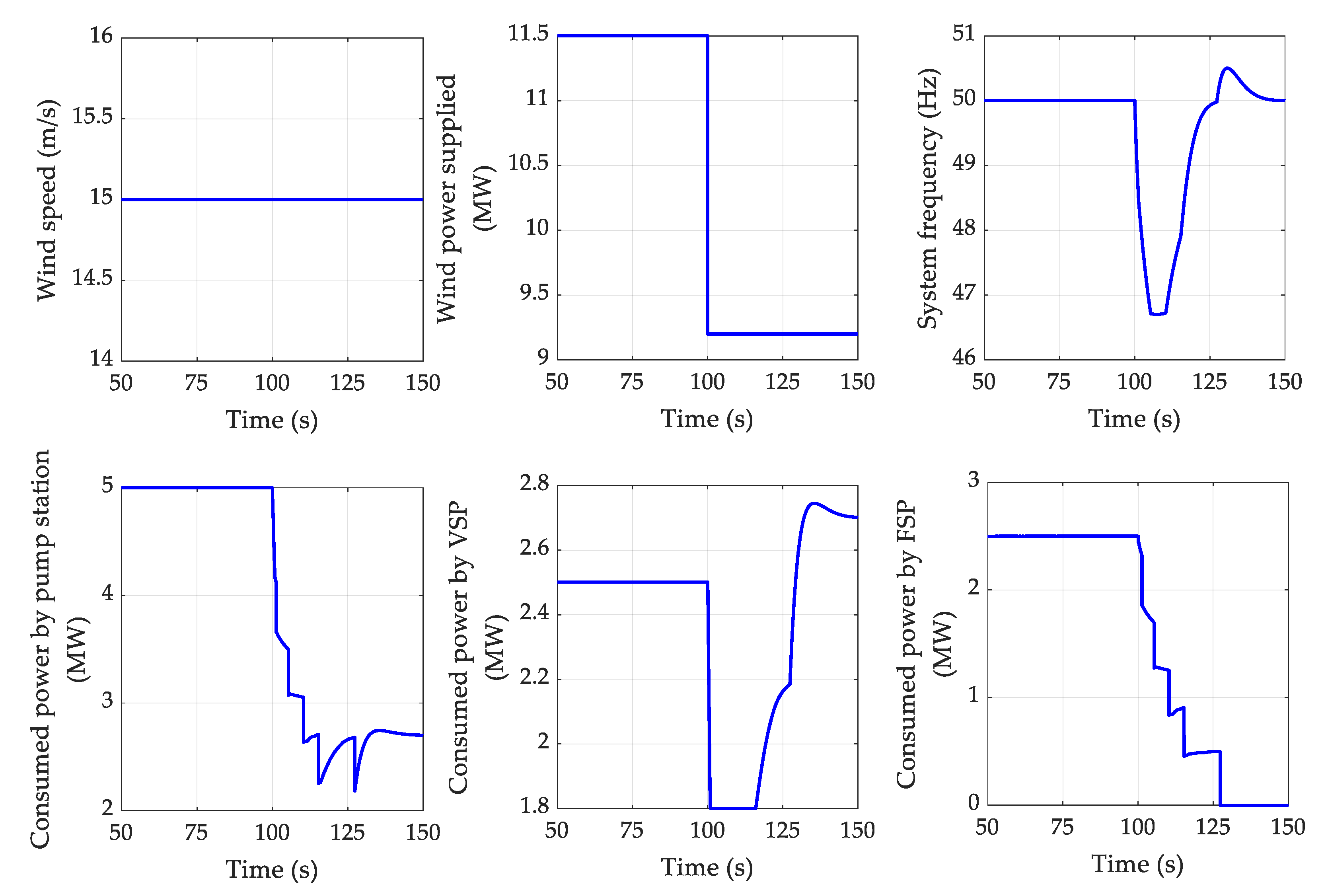
A sudden and unexpected disconnection of one of the five wind generators (2.3 MW)—the worst unexpected incident that may take place in the considered scenario—is considered as an abnormal situation in this power system [35]. For this simulation, the five VSWTs are connected supplying their rated power, the power demand is 6.5 MW and the power consumed by the power station is 5 MW: 2 × 1.25 MW by VSPs and 5 × 0.5 MW by FSPs. It is assumed that the wind generation does not participate in frequency regulation; thus, the pump station should decrease its consumed power to compensate the generation loss and recover the frequency.
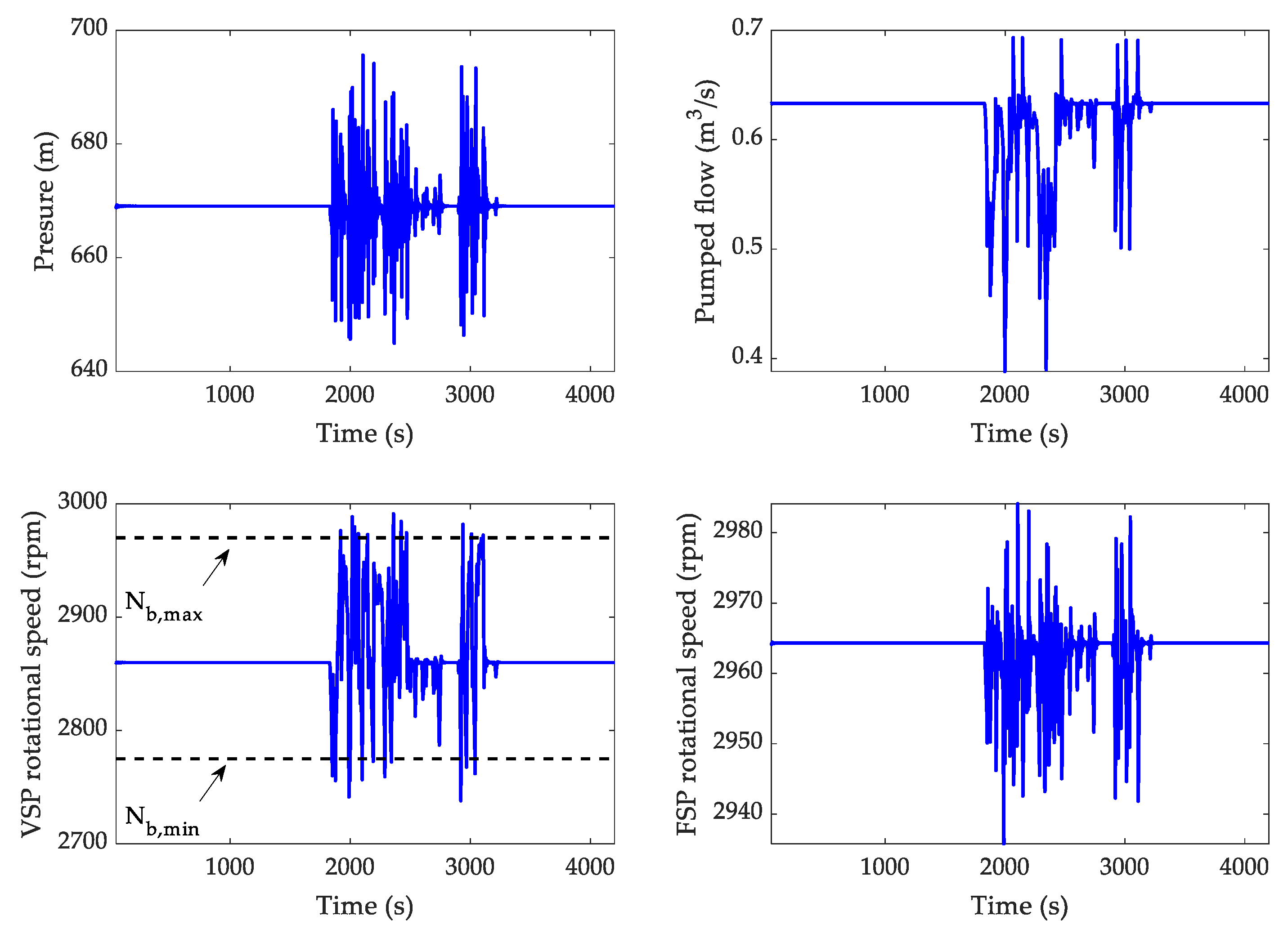
The VSWT disconnection produces a strong reduction of frequency, (see Figure 11). It can also be seen that the power absorbed by VSPs decreases extremely fast until their lower limit (900 kW) for trying to restore frequency. The rotational speed consequently decreases exceeding its minimum value. Therefore, according to the sharp frequency drop, all the FSPs initially connected are gradually switched off, as seen in Figure 12. Final nadir is 46.70 Hz, so this value complies with quality regulation requirements [34], provided that this event does not occur more than once a week.
The pressure and the flow in the penstock do not present extreme values (see Figure 12). A dynamic oscillation, corresponding to the water hammer elastic phenomena in the penstock, can be observed in the pressure representation.
6. Conclusions
This paper has studied the frequency control in an isolated system consisting of diesel units and a hybrid wind pumped-storage hydropower plant. The PSHP is divided into a hydropower plant equipped with four Pelton turbines and a pump station equipped with both fixed- and variable-speed pumps. The implementation of a new, dual frequency controller when the intensity of wind power is higher than the power demand has been analyzed so that the frequency regulation could be provided only by VSPs and FSPs. The lack of inertia in the system is solved by Pelton turbines, which operate as synchronous condensers. In this way, diesel units may be disconnected, decreasing generation costs and greenhouse gas emissions.
A dynamic model of the power system has been developed in Matlab Simulink to obtain the system dynamic response and check the effectiveness of the new controller. The main elements of this model are the power system, the pump station, and the VSWTs. The frequency deviation of the power system has been modeled by means of an aggregate inertial model. The pump station model includes—apart from the controller—hydraulic components (penstock, manifold, pipes, etc.), and different mechanical and electrical parts of the pumps. Finally, data from manufactures and a transfer function has been used to obtain the power provided by VSWTs from the wind speed.
The proposed controller has two different levels: variable-speed and fixed-speed control. Frequency deviations are initially corrected by means of a PI controller, which modifies the power consumed by the VSPs. Therefore, frequency fluctuations are corrected through an adjustment of the power reference tracked by the converter of the VSPs. VSPs regulating capacity is restricted because of their rotational speed limits. Thus, when the rotational speed of any VSP is near its limit, the FSPs controller acts by ordering to start up or switch off the necessary number of FSPs. In this manner, the VSPs will decrease or increase their power into the normal operation power range.
Two different simulations have been carried out in order to analyze the dynamic response of the system when the dual pump controller is introduced, paying special attention to the frequency. On the one hand, an event that may occur frequently has been modeled (normal operating conditions), i.e., fluctuations in the power supplied by wind turbines due to variations in wind speed. On the other hand, an unlikely event has been simulated (abnormal operating conditions), i.e., a sudden and unexpected disconnection of one of the five wind generators.
Simulation results have shown that in both cases, the frequency never exceeds the regulation limits and that all the hydraulic and mechanical variables present normal values. It is noticeable that the hierarchical sequence used to start or disconnect the FSPs by the controller should be changed properly so that wear of the six machines are the same. Therefore, as a general conclusion, the proposed controller could reduce the necessity of diesel units when there is high wind power production. It would be interesting, as a future line of work, to economically and environmentally measure the implications of introducing the proposed controller in El Hierro Island.
It is important to highlight that nowadays, according to the current Spanish legislation, this control strategy cannot be implemented because consumers, such as pump stations, are not allowed to provide ancillary regulation services.
Author Contributions
The authors have contributed to the completion of this paper according to the following list of tasks: conceptualization, C.A.P.; methodology, J.I.S.; software, G.M.-L.; validation, J.I.S. and G.M.-L.; resources, J.I.S. and C.A.P.; writing—original draft preparation, J.I.S., G.M.-L., C.A.P., and J.A.S.-F.; writing—review and editing, J.I.S., G.M.-L., C.A.P., and J.A.S.-F.; supervision, J.A.S.-F.
Funding
This research was funded by Ministerio de Economía, Industria y Competitividad, Gobierno de España under the project “Value of pumped-hydro energy storage in isolated power systems with high wind power penetration” of the National Plan for Scientific and Technical Research and Innovation 2013–2016 (Ref. ENE2016–77951–R).
Acknowledgments
The authors would like to thank Rafael Gómez Sánchez-Girón for the preliminary analyses that he did as part of the end-of-degree assignments.
Conflicts of Interest
The authors declare no conflict of interest.
Nomenclature
| a | [m/s] | Wave speed |
| ch,i,bh,i,ah,i | Coefficients of pump characteristic function | |
| cp,i,bp,i,ap,i | Coefficients of pump characteristic function | |
| Dnet | [p.u.] | System damping |
| f | [p.u.] | System frequency |
| fref | [p.u.] | Reference system frequency (50Hz) |
| g | [m/s2] | Gravity acceleration |
| Hb | [m] | Base head |
| hhr | [p.u.] | Higher reservoir water lever |
| hi | [p.u.] | Head at the end of the i-th Γ element of the penstock |
| hlr | [p.u.] | Lower reservoir water lever |
| hm | [p.u.] | Manifold pressure |
| hn,i | [p.u.] | Pumped head by each pump |
| hp,i | [p.u.] | Water pressure downstream each pump |
| Hwt | [s] | VSWT inertia time |
| i | Pump number | |
| j | VSWT number | |
| Ji | [s] | Rotor pump inertia |
| Ki | Integral gain | |
| Kp | Proportional gain | |
| L | [m] | Penstock length |
| Lp,i | [m] | Length of the conduit between manifold and each pump |
| Nb | [rpm] | Base rotational speed |
| Nbmax | [rpm] | VSP maximum rotational speed |
| Nbmin | [rpm] | VSP minimum rotational speed |
| Nnom,i | [rpm] | Nominal rotational speed of each pump |
| nnom,i | [p.u.] | Nominal rotational speed of each pump |
| np,i | [p.u.] | Rotational speed of each pump |
| Nsyn | [rpm] | Synchronous speed |
| nt | Number of segments of the penstock | |
| Pb | [MW] | Base power |
| pd | [p.u.] | Power demanded |
| pe,i | [p.u.] | Power consumed by each pump |
| pe,i0 | [p.u.] | Initial power consumed by each pump |
| Pnom,i | [MW] | Nominal power of each pump |
| pp,i | [p.u.] | Mechanical power of each pump |
| pref,i | [p.u.] | Reference power of each VSP |
| pw,j | [p.u.] | Wind power |
| Pw | [MW] | VSWT rated power |
| Qb | [m3/s] | Base flow in the penstock |
| Qb,i | [m3/s] | Base flow of each pump |
| qi | [p.u.] | Flow at the end of the i-th Γ element of the penstock |
| Qnom,i | [m3/s] | Nominal flow of each pump |
| qp,i | [p.u.] | Flow pumped by each pump |
| qt | [p.u.] | Flow at the manifold |
| r/2 | [p.u.] | Continuous head losses coefficient in the penstock |
| rp,i/2 | [p.u.] | Continuous head losses coefficient in each conduit between pump and manifold |
| S | [m2] | Penstock section |
| snom | Electrical machine slip | |
| Sp,i | [m2] | Section of the conduit between manifold and each pump |
| Te | [s] | Elastic time (=L/a) |
| Ti | [s] | VSWT transfer function constant time |
| Tm | [s] | Hydraulic unit mechanical starting time |
| Tw | [s] | Penstock water starting time |
| Twp,i | [s] | Conduit between manifold and each pump water starting time |
Appendix A. Model Numerical Values

Table A1.
Power system and variable-speed wind turbine (VSWT) parameters.
| Power System | VSWT | ||
|---|---|---|---|
| Pb | 11.5 MW | Pw | 2.3 MW |
| Dnet | 0.5 p.u. | Ti | 0.4 s |
| Tm | 5.91 s | Hwt | 1.971 s |
Table A2.
Hydraulic system parameters.
| Qb | Tw | 0.644 s | 0.030 p.u. | ||
|---|---|---|---|---|---|
| Hb | 665 m | Twp,i (i = 1, 8) | 0.017 s | (i = 1, 8) | 0.002 p.u. |
| Te | 2.53 s | Twp,i (i [2, 7]) | 0.032 s | (i [2, 7]) | 0.006 p.u. |
Table A3.
Fixed-speed pump (FSP) and variable-speed pump (VSP) parameters.
| FSP (i [2, 7]) | VSP (i = 1, 8) | ||||||||||
|---|---|---|---|---|---|---|---|---|---|---|---|
| Pnom,i | 0.5 MW | ah,i | 1.244 | ap | 0.553 | Pnom,i | 1.5 MW | ah,i | 1.169 | ap | 0.524 |
| Nnom,i | 2965 rpm | bh,i | 0.500 | bp | 0.638 | Nnom,i | 2973 rpm | bh,i | 0.173 | bp | 0.397 |
| Qnom,i | 0.056 | ch,i | −0.737 | cp | −0.190 | Qnom,i | 0.183 | ch,i | −0.333 | cp | 0.080 |
| Nsyn | 3.000 rpm | Ji | 0.35 s | Nb | 3.000 rpm | Nsyn | 3.000 rpm | Ji | 0.27 s | Nb | 3.000 rpm |
Table A4.
VSP controller gains.
| Kp | 10 1 | Ki | 2 1 |
1 These controller gains have been obtained applying the Ziegler–Nichols method.
References
- Pérez-Díaz, J.I.; Chazarra, M.; García-González, J.; Cavazzini, G.; Stoppato, A. Trends and challenges in the operation of pumped-storage hydropower plants. Renew. Sustain. Energy Rev. 2015, 44, 767–784. [Google Scholar] [CrossRef]
- Dursun, B.; Alboyaci, B.; Gokcol, C. Optimal wind-hydro solution for the Marmara region of Turkey to meet electricity demand. Energy 2011, 36, 864–872. [Google Scholar] [CrossRef]
- Ursat, X.; Jacquet-Francillon, H.; Rafai, I. Expérience d’EDF dans l’exploitation des STEP françaises. La Houille Blanche 2012, 3, 32–36. [Google Scholar] [CrossRef]
- Destro, N.; Korpas, M.; Sauterleute, J. Smoothing of offshore wind power variations with Norwegian pumped hydro: Case study. Energy Procedia 2016, 87, 61–68. [Google Scholar] [CrossRef] [Green Version]
- Singh, R.; Chelliah, T.; Agarwal, P. Power electronics in hydro electric energy systems—A review. Renew. Sustain. Energy Rev. 2014, 32, 944–959. [Google Scholar] [CrossRef]
- Valavi, M.; Nysveen, A. Variable-Speed Operation of Hydropower Plants: A Look at the Past, Present, and Future. IEEE Ind. Appl. Mag. 2018, 24, 18–27. [Google Scholar] [CrossRef]
- Bessa, R.; Moreira, C.; Silva, B.; Filipe, J.; Fulgencio, N. Role of pump hydro in electric power systems. J. Phys. Conf. Ser. 2017, 813, 012002. [Google Scholar] [CrossRef] [Green Version]
- Kirby, B. Frequency Regulation Basics and Trends; Oak Ridge National Laboratory: Oak Ridge, TN, USA, 2004.
- Vasconcelos, H.; Moreira, C.; Madureira, A.; Pecas Lopes, J.; Miranda, V. Advanced Control Solutions for Operating Isolated Power Systems: Examining the Portuguese islands. IEEE Electrif. Mag. 2015, 3, 25–35. [Google Scholar] [CrossRef]
- Rodrigues, E.; Osório, G.; Godina, R.; Bizuayehu, A.; Lujano-Rojas, J.; Catalão, J. Grid code reinforcements for deeper renewable generation in insular energy systems. Renew. Sustain. Energy Rev. 2016, 53, 163–177. [Google Scholar] [CrossRef]
- Martinez-Lucas, G.; Sarasúa, J.I.; Sánchez-Fernández, J.Á.; Wilhelmi, J.R. Frequency control support of a wind-solar isolated system by a hydropower plant with long tail-race tunnel. Renew. Energy 2016, 90, 362–376. [Google Scholar] [CrossRef] [Green Version]
- Martínez-Lucas, G.; Sarasúa, J.I.; Sánchez-Fernández, J.Á. Frequency Regulation of a Hybrid Wind–Hydro Power Plant in an Isolated Power System. Energies 2018, 11, 239. [Google Scholar] [CrossRef]
- Beires, P.; Vasconcelos, M.; Moreira, C.; Peças Lopes, J. Stability of autonomous power systems with reversible hydro powerplants. A study case for large scale renewables integration. Electr. Power Syst. Res. 2018, 158, 1–14. [Google Scholar] [CrossRef]
- Martínez-Lucas, G.; Sarasúa, J.I.; Sánchez-Fernández, J.Á. Eigen analysis of wind–hydro joint frequency regulation in an isolated power system. Electr. Power Energy Syst. 2018, 103, 511–524. [Google Scholar] [CrossRef]
- Shankar, V.K.A.; Umashankar, S.; Paramasivam, S.; Hanigovszki, N. A comprehensive review on energy efficiency enhancement initiatives in centrifugal pumping system. Appl. Energy 2016, 181, 495–513. [Google Scholar] [CrossRef]
- Filipe, J.; Bessa, R.; Moreira, C.; Silva, B. On the Profitability of Variable Speed Pump-Storage-Power in Frequency Restoration Reserve. J. Phys. Conf. Ser. 2017, 813, 012010. [Google Scholar] [CrossRef] [Green Version]
- Chazarra, M.; Pérez-Díaz, J.; García-González, J. Optimal Joint Energy and Secondary Regulation Reserve Hourly Scheduling of Variable Speed Pumped Storage Hydropower Plants. IEEE Trans. Power Syst. 2018, 33, 103–115. [Google Scholar] [CrossRef]
- Lung, J.-K.; Lu, Y.; Hung, W.-L.; Kao, W.-S. Modeling and Dynamic Simulations of Doubly Fed Adjustable-Speed Pumped Storage Units. IEEE Trans. Energy Convers. 2007, 22, 250–258. [Google Scholar] [CrossRef]
- Mercier, T.; Oliver, M.; Dejaeger, E. Operation ranges and dynamic capabilities of variable-speed pumped-storage hydropower. J. Phys. Conf. Ser. 2017, 813, 012004. [Google Scholar] [CrossRef] [Green Version]
- Nicolet, C.; Pannatier, Y.; Kawkabani, B.; Schwery, A.; Avellan, F.; Simond, J.-J. Benefits of Variable Speed Pumped Storage Units in Mixed Islanded Power Network during Transient Operation. In Proceedings of the 16th Annual Hydro Conference, Lyon, France, 26–28 October 2009. [Google Scholar]
- Suul, J.A.; Uhlen, K.; Undeland, T. Wind power integration in isolated grids enabled by variable speed pumped storage hydropower plant. In Proceedings of the 2008 IEEE International Conference on Sustainable Energy Technologies (ICSET), Singapore, 24–27 November 2008. [Google Scholar]
- Iglesias, G.; Carballo, R. Wave resource in El Hierro—An island towards energy self-sufficiency. Renew. Energy 2011, 36, 689–698. [Google Scholar] [CrossRef]
- Pezic, M.; Cedrés, V.M. Unit commitment in fully renewable, hydro-wind energy systems. In Proceedings of the 2013 10th International Conference on the European Energy Market (EEM), Stockholm, Sweden, 27–31 May 2013. [Google Scholar]
- Platero, C.; Nicolet, C.; Sánchez, J.; Kawkabani, B. Increasing wind power penetration in autonomous power systems through no-flow operation of Pelton turbines. Renew. Energy 2014, 68, 515–523. [Google Scholar] [CrossRef] [Green Version]
- Canary Government. Anuario Energético de Canarias 2016; Consejería de Economía, Industria, Comercio y Conocimiento: Santa Cruz de Tenerife, Spain, 2017.
- Mansoor, S.; Jones, D.; Bradley, F.; Jones, G. Reproducing oscillatory behaviour of a hydroelectric power station by computer simulation. Control Eng. Pract. 2000, 8, 1261–1272. [Google Scholar] [CrossRef]
- O’Sullivan, J.; Power, M.; Flynn, M.; O’Malley, M. Modelling of frequency control in an island system. In Proceedings of the IEEE Power Engineering Society 1999 Winter Meeting, New York, NY, USA, 31 January–4 February 1999. [Google Scholar]
- Pérez-Díaz, J.I.; Sarasúa, J.I.; Wilhelmi, J.R. Contribution of a hydraulic short-circuit pumped-storage power plant to the load–frequency regulation of an isolated power system. Electr. Power Energy Syst. 2014, 62, 199–211. [Google Scholar] [CrossRef]
- Souza, O.H.; Barberi, N.; Santos, A.H.M. Study of hydraulic transients in hydropower plants through simulation of nonlinear model of penstock and hydraulic turbine model. IEEE Trans. Power Syst. 1999, 14, 1269–1272. [Google Scholar] [CrossRef]
- Chaudhry, M. Applied Hydraulic Transients, 2nd ed.; Van Nostrand: New York, NY, USA, 1987. [Google Scholar]
- Andrews, R. An Independent Evaluation of the El Hierro Wind & Pumped Hydro System. 23 February 2017. Available online: http://euanmearns.com/an-independent-evaluation-of-the-el-hierro-wind-pumped-hydro-system/ (accessed on 25 September 2018).
- ENERCON GmbH. ENERCON Product Overview; Technical Report for ENERCON: Bremen, Germany, 2016. [Google Scholar]
- Martínez-Lucas, G.; Pérez-Díaz, J.I.; Chazarra, M.; Sarasúa, J.I.; Cavazzini, G.; Pavesi, G.; Ardizzon, G. Risk of penstock fatigue in pumped-storage power plants operating with variable speed in pumping mode. Renew. Energy 2018, 133, 636–646. [Google Scholar] [CrossRef]
- European Standards EN 50160, Voltage Characteristics of Electricity Supplied by Public Distribution Networks; CEN-CENELEC: Brussels, Belgium, 2007.
- Martínez-Lucas, G.; Sarasúa, J.I.; Sánchez, J.Á.; Wilhemi, J.R. Power-frequency control of hydropower plants with long penstocks in isolated systems with wind generation. Renew. Energy 2015, 83, 245–255. [Google Scholar] [CrossRef] [Green Version]
Figure 1.
El Hierro hybrid wind pumped-storage hydropower plant (W-PSHP) system.

Figure 2.
El Hierro power system, simplified one-line diagram.

Figure 3.
Scheme of the penstock model.

Figure 4.
Pump station hydraulic scheme.

Figure 5.
Variable-speed wind turbine power curve.

Figure 6.
Variable-speed and fixed-speed control system layout.

Figure 7.
“Discrete Controller Fixed-Speed Pumps” layout.

Figure 8.
System frequency and power supplied and demanded when a wind speed fluctuation is simulated.
Figure 8.
System frequency and power supplied and demanded when a wind speed fluctuation is simulated.

Figure 9.
Pressure and flow in the penstock and pumps rotational speed when a wind speed fluctuation is simulated.
Figure 9.
Pressure and flow in the penstock and pumps rotational speed when a wind speed fluctuation is simulated.

Figure 10.
Power consumed by the pumps when a wind speed fluctuation is simulated.

Figure 11.
System frequency, power supplied and demanded when a variable-speed wind turbine (VSWT) disconnection takes place.
Figure 11.
System frequency, power supplied and demanded when a variable-speed wind turbine (VSWT) disconnection takes place.

Figure 12.
Pressure and flow in the penstock, pumps rotational speed, and power consumed when a VSWT disconnection takes place.
Figure 12.
Pressure and flow in the penstock, pumps rotational speed, and power consumed when a VSWT disconnection takes place.

Table 1.
Energy supplied by each generation technology during 2016 [25].
Table 1.
Energy supplied by each generation technology during 2016 [25].
| Demand | Energy Supplied | ||
|---|---|---|---|
| Hydropower Plant | VSWTs | Diesel Generators | |
| 58.58 MWh | 2.13 MWh | 28.88 MWh | 27.58 MWh |
| 100% | 3.63% | 49.29% | 47.07% |
© 2018 by the authors. Licensee MDPI, Basel, Switzerland. This article is an open access article distributed under the terms and conditions of the Creative Commons Attribution (CC BY) license (http://creativecommons.org/licenses/by/4.0/).
Share and Cite
MDPI and ACS Style
Sarasúa, J.I.; Martínez-Lucas, G.; Platero, C.A.; Sánchez-Fernández, J.Á. Dual Frequency Regulation in Pumping Mode in a Wind–Hydro Isolated System. Energies 2018, 11, 2865. https://doi.org/10.3390/en11112865
AMA Style
Sarasúa JI, Martínez-Lucas G, Platero CA, Sánchez-Fernández JÁ. Dual Frequency Regulation in Pumping Mode in a Wind–Hydro Isolated System. Energies. 2018; 11(11):2865. https://doi.org/10.3390/en11112865
Chicago/Turabian StyleSarasúa, José Ignacio, Guillermo Martínez-Lucas, Carlos A. Platero, and José Ángel Sánchez-Fernández. 2018. "Dual Frequency Regulation in Pumping Mode in a Wind–Hydro Isolated System" Energies 11, no. 11: 2865. https://doi.org/10.3390/en11112865
Note that from the first issue of 2016, this journal uses article numbers instead of page numbers. See further details here.