Urban and Extra-Urban Hybrid Vehicles: A Technological Review


Department of Mechanical and Aerospace Engineering, University of Roma “Sapienza”, 00184 Roma, Italy
Energies 2018, 11(11), 2924; https://doi.org/10.3390/en11112924
Submission received: 12 September 2018
/
Revised: 10 October 2018
/
Accepted: 17 October 2018
/
Published: 26 October 2018
(This article belongs to the Special Issue 10 Years Energies - Horizon 2028)
Abstract
:Pollution derived from transportation systems is a worldwide, timelier issue than ever. The abatement actions of harmful substances in the air are on the agenda and they are necessary today to safeguard our welfare and that of the planet. Environmental pollution in large cities is approximately 20% due to the transportation system. In addition, private traffic contributes greatly to city pollution. Further, “vehicle operating life” is most often exceeded and vehicle emissions do not comply with European antipollution standards. It becomes mandatory to find a solution that respects the environment and, realize an appropriate transportation service to the customers. New technologies related to hybrid–electric engines are making great strides in reducing emissions, and the funds allocated by public authorities should be addressed. In addition, the use (implementation) of new technologies is also convenient from an economic point of view. In fact, by implementing the use of hybrid vehicles, fuel consumption can be reduced. The different hybrid configurations presented refer to such a series architecture, developed by the researchers and Research and Development groups. Regarding energy flows, different strategy logic or vehicle management units have been illustrated. Various configurations and vehicles were studied by simulating different driving cycles, both European approval and homologation and customer ones (typically municipal and university). The simulations have provided guidance on the optimal proposed configuration and information on the component to be used.
Keywords:
hybrid electric vehicle; series and parallel configuration; energy management; control strategies; electronic controller unit; braking energy regeneration; hybridization degree; powertrain configurations; battery package; ultracapacitor; electric motors; thermal engines; ultra-micro gas turbine; driving cycles simulations; hybrid vehicle feasibility1. Introduction
Public and private transport play a key role in the economic and social development of each country. An efficient transport system allows the possibility to reach new markets and strengthen existing ones. Consequently, it allows and promotes a strong economic growth which is globally productive and competitive. An inefficient or low-efficient system produces an increase in traffic congestion, economic and social losses, and loss of working hours, productivity, and social relations. World Transportation absorbs 1975 million tons of oil equivalent (Mtoe) [1] per year, that is, 26% of energy consumption. However, if average energy consumption for transport is 0.32 toe/inhabitant (tons of oil equivalent per capita), consumption varies considerably from one continent to another: A European citizen consumes 0.88, a North American an average of about 2.21, and an African one 0.07 toe. Now, motorized mobility, as it is practiced in “developed” countries, is becoming increasingly unsustainable. Indiscriminate use of motorized transport has three main consequences:
- It is dangerous. In 2014, the World Health Organization (WHO) defined transport as “a first class medical drama” that causes over 3000 deaths per day and affects 90% of the world’s poorest countries (those with a lower degree of motorized transport);
- Motorized transport excludes other modes of transport. It has difficulties tolerating pedestrians, cyclists, and public transport and forces them to protect themselves (construction of sidewalks, bike paths, green areas) or to retreat underground (subway).
- Motorized transport model space in favor of sparsely populated cities is very scattered. The most obvious example is that of West Coast American cities (with a population density lower than 25 people per hectare and a consumption for transport which is more than 1.5 toe/inhabitant). On the other extreme are Asian cities, exemplified by Hong Kong (with a density of almost 350 inhabitants per hectare and a consumption of 0.1 toe/inhabitant).
In addition, the greenhouse gas emissions of motorized transport are estimated at 6301 MtCO2, or 26% of global CO2 emissions [1]. Transportation systems are the biggest polluters in the world due to the use of fossil fuel in public and private vehicles. For this reason, after Kyoto, the EU is promoting more and more innovative transport systems with limited environmental impact. There is currently a new momentum in the study and implementation of efficient vehicles, such as electric vehicles, hybrids, and gas. In medium/long term, global trends will lead to a further increase in demand for transport, which will exceed the current capacity of existing systems. It can be remembered that pollution is concentrated mainly in large urban areas, where the high presence of population and related activities cause a high concentration and emission in the air. The main causes are the increasing territory anthropization with an increasing demand for energy sources, mobility, and industrial development. Secondly, system emissions consist of carbon monoxide CO, carbon dioxide CO2, nitrogen oxide NOx, and other compounds, such as lead Pb, benzene C6H6, and particulate matter (PM). Pollution not only damages the environment, but also damages human health. For these reasons, in recent years, the EU, through a series of regulations, has gradually limited concentrations of pollutants (particulate matter, SO2, Pb, NOx, CO, and benzene). Across Europe, these substances are released by several factors. In detail [1], for PM10:
- Transport 36% (2/3 due to wheeled transportation);
- Industry 26%;
- Civil industry 17%;
- Agriculture 11%.
As can be noticed, transport is the main factor “responsible” for air pollution, especially in large urban areas, where population density and transportation reach high levels, causing 70% of total emissions. There is a growing demand for vehicles by the world’s population (2.8% average per year), but fortunately there is no longer a high content of benzene and lead in fuel. Most deliveries of goods are done by truck (61.5%), whereas 21.7% are done by rail and 11.5% by ships. Finally, thin particles and, in particular, ozone continue to present serious health risks: Safety limits for these substances are regularly exceeded because in many regions and cities, EU air quality objectives and regulations are not met. The poor air quality has a high impact on the quality of life, as well as causing asthma and respiratory problems. To control vehicle emissions, the EU has created regulations which classify vehicles (Table 1) according to their production of pollutants. Let us consider a briefly economic survey—for example, the case of the city of Rome. From an economic point of view, the traffic, produced by the intensive use of private vehicles and the high offer of parking (76,048 paid parking and 18,204 free parking spots, with a limit of 3 h for non-residents), generates congestion levels that are expressed through 135 million hours lost per year, for daily transportation.
In economic terms, this is a loss of about €1.5 billion/year. Added to this value should be the social costs for road accidents (approximately 1.3 billion euros per year) and the environment [2]. According to UN (United Nations) reports, the current global scenario is characterized by the following situation:
- Transport inefficiencies costing, globally, between 1 and 2 trillion $ per year;
- That congestion is responsible for, approximately, 1% (100 billion) of GDP in developed economies.
2. Electric Vehicles (EVs) & Hybrid Vehicles (HVs) Definition
First of all, a distinction is needed between “traction” and “propulsion”. Traction is supplied by the electric motor, while propulsion can be electrical or thermal, or by coupling the two engines. If the electric motor receives the required energy from a battery package, the vehicle is considered all-electric vehicle [2,3,4]. This vehicle needs recharging stations, consistent with the operational battery package autonomy, which affect the vehicle range. If the electric motor is fed by the battery package and by a thermal engine, the vehicle is called “hybrid”. In fact, this vehicle is a thermal–electric vehicle. Despite the fact that electric vehicles (EVs), either all-electric or hybrid, represent an effective solution for reducing “local” emissions (city, extra urban agglomerations), they cannot affirm the same concepts, considering the whole production chain. A compromise solution has to be found.
2.1. Briefly Electric Vehicle Description
In an electric vehicle, the engine that supplies power to the wheels is an electric motor powered by a battery pack. The battery package is rechargeable and a vehicle management unit (VMU) manages and distributes the energy flows to and from the electric motor. The electric motor can be an AC or DC one. The DC motor is cheaper and easier to maintain/build. These motors can also work, for a limited time, under “overdrive” conditions, absorbing more energy than the rated one. This aspect is very beneficial during acceleration. The use of the overdrive is limited by the risk of overheating. The AC motor (typical three-phase) is more expensive. In addition, a kinetic energy recover system (KERS) is expected to be present on a vehicle. This device is able to recover 15% regenerative braking [5]. The last important aspect is the battery package. For eliminating lead acid batteries, which are pollutant, bulky, heavy, expensive, and characterized by an excessive charge time, researchers’ attention has settled on lithium-ion batteries (Li-ion) or nickel (NiMH). This latter type of batteries has a long service life. However, the cost of these battery packs is very high. Finally, there is the charging system, which is necessary for a vehicle’s operation. In all the aforementioned aspects, electric vehicle technology is constantly evolving, responding to continuous and variable market demand. A comparison between Electric Vehicle and Hybrid Vehicle is reported in Table 2.
2.2. Hybrid Vehicles
A hybrid vehicle, more properly a hybrid powered vehicle, is a vehicle equipped with a propulsion system composed of two or more components, such as an electric motor with a thermal engine, which work in synergy with each other [6,7,8,9,10,11,12]. It must not to be confused with bimodal vehicles, which are vehicles that can operate with energy supplied from the outside or with a battery on board, such as trolleybuses with batteries. There are three possible configurations:
- 1
- Series
- 2
- Parallel
- 3
- Combined
2.2.1. Series Hybrid
This technology, also called a “range extender” (Figure 1a), is very similar to that used in diesel–electric locomotives. The internal combustion engine (ICE) is not directly connected to the wheels, and has two functions:
- (a)
- Generate the electricity to power the electric motor;
- (b)
- Recharge the batteries.
In some configurations, it is possible that the heat engine carries out both functions. If a large amount of energy is required, it is drawn from both the heat engine and the battery package. Because electric motors are able to operate on a wide range of engine speeds, this structure allows to remove or simplify the mechanical transmission device. The efficiency of ICE changes with speed control, so the heat engine rpms (revolution per minute) in a series hybrid system are set to get maximum efficiency (the engine does not suffer either acceleration or deceleration). Thanks to this condition, it can use a heat engine (generator), which has a very narrow range of exploitation/operation compared to common heat engines, with a higher efficiency in that “limited” range. In some prototypes, small electric motors can be installed for each wheel (Electric Motor-wheel). The advantage of this arrangement is that the power delivered to each wheel can be controlled and managed separately. On the other hand, a complex vehicle management (that has to operate as a mechanical differential) is required. The drawback of series hybrid vehicles is the reduction of efficiency in conditions of high and constant speed (typically on the highway, with a “constant” speed of 130 km/h). In this configuration, part of the energy is lost, which does not happen in classical vehicle configuration. Series hybrid [10,12,13] is the most recommended configuration for vehicles that require continuous braking and restarts, such as for buses and taxis and some heavy operating ones. In Table 3 the main HV characteristics.
2.2.2. Parallel Hybrid
Parallel hybrid (Figure 1b) is the most widely used architecture [6,7,8,9,10,11,12,13,14,15]. Both motors (electric and thermal) provide power to the wheels. The ICE is also used to recharge the battery package, when required. The position of the mechanical coupling within the system identifies three possibilities: (a) A pre-transmission (the electric motor is upstream the gearbox), (b) post-transmission (the electric motor is downstream), and (c) post-wheels (wheels have two independent motors).
There is a further classification, connected to the relationship between the rated powers. In most cases, the ICE is dominant, and the electric motor provides (when requested) a surplus of power. Often, the electric motor and the electric generator are combined into a single device. This allows to eliminate the “low gears”, characterized by higher fuel consumption. In addition, the ICE displacement can be lower, as the electric motor provides the surplus. This makes these vehicles suitable for urban driving cycles rather than extra urban cycles (Table 4).
2.2.3. Combined Hybrid
These hybrid vehicles are characterized by a mechanical coupling (typical for parallel hybrid) and hybrid electrical connections (typical series hybrid). Two electric motors are used. A relatively simple example is provided by the architecture of the Toyota Prius. The mechanical coupling between the internal combustion engine and the final drive shaft has been realized through the combination of a planetary gear train and a gearbox.
2.2.4. Hybrid Electric Vehicles: Passenger Sedans, Sports Cars, City Cars
There are actually several commercial hybrid vehicles available on the market. In the following paragraph, several models are reported, with a brief description. It is only a “picture” of the existing vehicles and possible future research and applications:
1. Toyota Prius (parallel hybrid)
The Toyota Prius was the first commercially mass-produced and marketed HEV. The Lexus model RX400h and RX450h, also produced by Toyota, have been characterized by a planetary gear technology with a third motor added to the rear wheel to increase the vehicle’s performance. In 2014, about nine million hybrid electric vehicles have been sold. Seven million of these are Toyota/Lexus models [16].
2. Honda Civic (parallel hybrid)
In the Honda Civic hybrid the electric motor is located between the ICE and the transmission. A 12-kW PM motor either provides assistance to the engine in high vehicle power demand or splits the power of the engine during low vehicle power demand. The hybrid vehicle report a 66% and 34% fuel economy, respectively.
3. Ford Escape (combined)
This was the first hybrid SUV. The model, as well as the Lexus ones, adopts the planetary gear concept as power splitting device. With significantly reduced engine dimensions, the hybrid SUV can be compared with standard combustion engine ones, in terms of performance. The continuous research and development has generated a second generation hybrid SUV: the Mercury Mariner, with improved power that allows to achieve an exceptional drivability and dynamic performance. Ford Motor Company reported sales of over o 375,000 hybrid vehicles in the US in 2015 [17].
4. Honda FCX (parallel)
This commercially available HEV uses fuel cell technology, thanks to the continuous improvement of this technology. In 2002, Honda’s FCX was certified by the US Environmental Protection Agency (EPA) and the California Air Resources Board (CARB). It was the only fuel cell car to be approved for commercial use. CARB and the EPA have also certified the FCX as a Zero-Emission Vehicle (ZEV), Tier-2 Bin 1 [6].
5. Saturn VUE
The Saturn VUE is a very simple and “on the field” solution. A 4-kW electric motor has added, through a belt, to the existing power train. The small electric motor is powered by 36 V 10 kW. The motor is configured in generating operational mode, either from the engine during opportunity charging or from the vehicle KERS system. An interesting 20% fuel economy improvement justifies the small investment into the hybrid. The drawback is that due to the small size motor, the engine cannot shut off at low vehicle speed.
2.2.5. Electric/Hybrid Buses in the Public Transport
1. The UTAH STATE electric bus (Aggie Bus)
The electric bus stops at a sort of “pit-stop”, where a grid re-charges the vehicle batteries. The recharging system is wireless.
2. E-Bus BYD C9
The development of this bus is funded by the Malaysian and Australian governments. The BYD C9 is 12 meters long and can carry up to 47 people, traveling at an average highway speed, with a range of 305 km. It is a 100% electric bus.
3. Terra Volt XR Extended Range bus
The Terra Volt XR has a 131 kWh battery package. In road tests the vehicle has shown a range of 1126 km, travelled in 24 h.
4. The CCS Byberg & Nordin Bus
The re-charging module is called Heliox CCS and it precisely meets the EU standard protocol for recharging with direct current (DC).
5. Staples & Siemens Fuel-cells bus
This is a thermo-electric vehicle with electric traction. The fuel cell is a device where hydrogen and oxygen chemically react producing electricity. If the fuel cell is mounted on a vehicle equipped with an electric motor (or motors), the hydrogen becomes a fuel that can replace fossil fuels.
At present, several programs are under development in some countries, such as Switzerland, England, the United States, Italy and others, to improve and realize an electric bus [18]. A first analysis of the various systems highlights a common criticism. At the present, all the prototypes are strongly affected by the “limited” operational range of batteries or battery packages, and require long recharge times. In some projects, to mitigate this aspect, the manufacturers have “oversized” the battery packages (see BYD systems and Terra Volt that use battery packages of 100 and 130 kWh respectively). This “oversizing” has, inevitably, an impact on the installation, operation and maintenance costs.
2.2.6. Other Hybrid Electric Vehicles
1. Trucks
In 2003, GM presented a hybrid diesel-electric military (light) truck, equipped with an AC combination of a diesel electric and a fuel cell auxiliary power unit. In 2004 other light trucks were presented by Mercedes Benz (Sprinter) and Micro-Vett SPA (Daily Bimodal). In 2005 the Isuzu Company realized the Elf Diesel Hybrid Truck for the Japanese Market. The company claimed sales of 300 vehicles [19,20]. Regarding the vehicles’ specific issues, two braking torque control strategies for the parallel power trains of hybrid duty trucks have been introduced [21]. Other research groups have presented a heavy duty truck equipped with two similar electric drive trains acting in parallel mode [22]. About the VMU, several groups [23,24] have studied and analyzed the optimal control strategies, especially for hybrid electric trucks and the control strategy and energy fluxes management have been presented [25].
2. Hybrid trains
Railroad transportation is a possible candidate for the implementation of hybrid systems. In some previous work, different configurations are presented. An Italian research group presented a gas turbine hybrid configuration (series hybrid) as a range extender for a passenger train [26]. Other researchers have presented a fuel cell hybrid locomotive [27,28]. In the different configurations presented, in one a fuel cell is the energy source, in the other a diesel engine is the power source. Other teams have investigated the advantages and drawbacks of the electric energy storage systems, using a combination of batteries and ultracapacitors [29,30].
3. Aircraft and UAVs
The Boeing concept is a manned full electrical aircraft that has a PEM fuel cell for cruising and a Li-ion battery for take-off and climbing [31]. Two different configurations are presented, unregulated and regulated. The unregulated architecture realizes a natural balance between energy/power sources. The regulated architecture controls the power supplied by each source. The converter output voltage is levered by a control loop that maximizes the fuel cell power. Several research groups have investigated the technical differences between More Electric Aircraft (MEA) and Hybrid Electric Vehicles (HEVs) [32]. The same previous Italian group has presented a UAV, in hybrid configuration [33]. The series hybrid is used, and the thermal source is again a gas turbine device. In this case the GT device acts as a “range extender”.
4. Electric boats
The electrification of ships is important for the reduction of oil use and pollution. In some papers the required design criteria and procedures were presented [34]. Actually the main configuration foresees a fuel cell stack (proton exchange membrane—PEM) and battery packages. The attention is focused on passenger boats. Finally, a plug-in boat (PHEB) was presented [35].
5. Helicopters
Following research on wheeled vehicles, helicopters have also been considered for implementing a hybrid power pack. In this vehicle, the minimization of the mass, the fuel consumption and the fulfilling of the instantaneous load power demand are mandatory. Secondary electric sources can be added to avoid over-sizing the main source and to optimize the management of the transient energy. a model based on Energetic Macroscopic Representation (EMR) has been used to realize a control structure [36].
6. Scooters (motorcycles)
for farm works and an Internal Combustion Engine Tractor (ICET) for European Undoubtedly, the development of hybrid electric motorcycles has much feasibility. A new hybrid motorcycle, that meets the EU standards, has been designed [37]. Researchers have then investigated the possibility of inserting a low cost KERS [38]. In this case, the energy storage is provided by ultra-capacitors. The configuration is parallel hybrid, where the innovative drive train is coupled with a conventional ICE [39,40].
7. Tractors
A research group has presented the life cycle analysis of a solar PV-based electric vehicle standards [41]. The lifecycle assessment of a Solar Assist Plug-in Hybrid electric Tractor (SAPHT) and its comparison with an ICET has been presented and analyzed [42].
8. Military vehicles
The United States Army Manned Ground Vehicles of the Future Combat System is focused on the use of hybrid electric vehicles. The system consists of a diesel engine to generate electrical power for mobility and all other vehicle subsystems. Eventually, development of all FCS land vehicles has ceased, due to the funds being blocked by the US Government. Recently, the control scheme of a military vehicle has been presented. The vehicle configuration has been based on an inversion of energetic macroscopic representation (EMR) [43,44].
2.3. Degree of Hybridization
The power in an HV is typically supplied by one electric motor (EM). The choice of the EM is a direct function of the required performance. On the contrary, the installed electric power sources may depend on different considerations. It is possible to identify two opposite solutions: the first configuration is a “single electric” source, with an overdesigned battery package generating all required electric power [4,9,10,12,18]. Such a vehicle is named a “Full Hybrid Vehicle”.
The second solution is defined as “Minimal Electric” or “Minimal Hybrid” source. Here a battery package and TE simultaneously provide all electric power to the EM. If one of these power fluxes is missing, the vehicle performance is significantly compromised (without the battery package the vehicle does not have sufficient power for traction, and without the ICE the vehicle is not able to supply energy to complete the typical homologation mission).
There are many other possible solutions, like “Plug-in Hybrid” and “Mild” or “Micro Hybrid”. In the first configuration, a plug-in hybrid electric vehicle (PHEV) is a vehicle with a rechargeable battery package that can be recharged by connecting a plug to an external electric grid. A PHEV shows the characteristics of both previous solutions [4,9,10,45,46,47]. Regarding Mild Hybrids, normally, the power levels are within 3 to 5 kW, but can increase to 7 ÷ 12 kW. In the common solution, the EM is located in the vehicle transmission at the engine crankshaft [11,12,48]. Therefore, some researchers have proposed a formula to define the degree of hybridization. In fact, once the vehicle class has been identified, the maximum required electric power is fixed. Then, the ICE total power source (if any) and battery package nominal specification, are computed. Finally it evaluates the hybridization degree (HD—the design target), as the correct ratio between the ICE power (if any) and the total installed power:
HD = PTHERMAL ENGINE/(PTHERMAL ENGINE + BP)
3. Hybrid Vehicles: Operative Description
The adoption of separate motors which can be used separately or simultaneously in hybrid vehicles offers great flexibility of power management, apart from operational reliability, concerning the high currents generated and delivered, the key issue concerns the overall dimensions and electrical characteristics of battery package, subjected to frequent and rapid charging and discharging cycles [4,9,10,11,12,45,46,47,48]. Therefore, only by focusing on the study of performance and cost of the vehicle, as well as on the cost and the actual battery life, the market can be stimulated to welcome the introduction of hybrid vehicles. The most sensitive parameter is the cost, and in the short term, the most interesting solution is the thermal-electric configuration, which ensures the reduction of fuel consumption and emissions, and preserves the current infrastructure network for refueling, without an abrupt disruption of the existing distribution system, as would be necessary in the case of widespread introduction of pure electric vehicles. The high technological level reached in electronics makes presumably easy to complete a control logical unit for managing position signals of pedals, instantaneous power demand, wheel speed, engines speed, emissions, fuel flow, temperature, pressure, voltage, current and battery State of Charge (SOC). The vehicle and the control system shall exchange continuous information: the processor processes the signals according to an established schedule (“mission control”) and sends commands to the actuators, achieving a balance between performance, consumption, mechanical problems and driving comfort. The electronics are thus crucial for a hybrid vehicle; In light of the need to connect different components to set up an intelligent system, a hybrid vehicle has multiple functional units, such as batteries, electric motors, generating set and charging converters, which must be coordinated through “intelligent devices”, to monitor and process data simultaneously from various elements. To avoid a complex central control module, it can be convenient to utilize a modular system, which provides for each unit its own processor, all connected via a bus, for the information exchange and coordination, namely a Vehicle Management Unit (VMU). There are currently four possible configurations of hybrid propulsion, using different internal combustion heat engines, or gas turbine, and different electric motors, AC or DC, synchronous and asynchronous, with different solutions in relation to the mission for which is primarily designed [45]. The choice between the different existing configurations of hybrid system, i.e., dual power, series, parallel, parallel with the combustion engine in a fixed nominal point, with various types of thermal and electrical motors, depends on the requirements of the vehicle type: today the most common features are:
- A small heat engine that delivers a small power with low pollutant emissions, but delivers very uninteresting performance during extra-urban missions.
- A larger internal combustion engine suitable for extra-urban and highway missions, but certainly not economically advantageous in urban cycles, with high consumption and emissions.
3.1. HV Powertrain Control and Management
The most critical aspect in a HEV project is the flow control and energy conversion for the thruster. Therefore, the realization and the choice of the control logic of the HEV is the key point. In This section it will try to give an overview of the various strategies of control powertrain for HEV and review the latest methods of these strategies. It can be remembered that the aim of the control strategies is to meet a set of objectives/targets/constraints [7,49,50,51,52]:
- Fuel consumption minimization;
- Fuel economy;
- Emissions minimization;
- Good drivability;
- Minimum system cost.
To achieve these goals, hardware configurations and powertrain control strategies are usually designed together [32].
3.2. Energy Management
The electric motors are powered by battery packs throughout electronic devices. The battery is recharged by an on-board TE, in addition to regenerative braking. The range of electric drive mode is very limited according to battery package rated power. A more powerful battery package increases the range and improves the overall fuel economy. Considering the abovementioned recharging solution, it is important to highlight that the current systems are not able and sufficient to fully recharge the battery packages. The typical operation modes are illustrated in Figure 3. In electric drive mode, at start up, the electric motor is fed by the batteries. The available power is determined by the SOC. Depending on the configuration chosen, during cruising, the TE can be recharging the batteries or split its power between the power train and batteries. In accelerating/passing maneuvering, the thermal engine and the battery packages supply energy to the powertrain. Eventually, a KERS regenerative braking system is considered. It converts the braking energy into electricity and stores it in the battery package. Besides, when the vehicle is stopped, all motors are shut down, because no idling is considered. At same time, the battery continues to supply energy for all on-board auxiliary systems (air conditioning, check panel lights, audio, etc.). The operational modes are determined by the energy management strategies. They can divided into two main topics [5,9,10,11,12,53]:
- Rule-Based (RB)
- Optimization-Based (OB)
3.3. The Rule-Based Control Strategy
Its effectiveness in real time supervisory control of power flows in a hybrid powertrain is its main favorable characteristic. The rules are based on heuristics, intuition, human expertise and mathematical models (Figure 4). Generally, “a priori” knowledge of a predefined driving cycle is not required, for compiling the rules. These rule-based approaches can be classified into deterministic and fuzzy- based methods. The rule strategy is based on the concept of “load leveling” [9,10,11,12,53]. Such a rule is normally adopted in “IC-dominated hybrids”. The ICE operates close to a pre-determined value, during every instant of the mission drive. Depending on the strategy target, the ICE can operate close to an optimal efficiency point or an optimal fuel economy one, respectively. In this case, the HD is higher, the ICE dominates and the EM and BP is usually downsized with lower efficiency compared to the thermal engine. Besides, this concept can be used in Not-ICE dominated hybrids. In fact, the thermal engine can operate at a fixed point [48], recharging the batteries and supply extra power only in “critical situations”, depending on the SOC. In this case, the TE acts as a “range extender”. In this configuration, the battery package and the electric motors are dominant compared to the engine, that can be downsized.
3.3.1. Deterministic Approach
Heuristic rule-based approaches are usually used to analyze the power/energy fluxes in a hybrid power train. To design the rules, thermal engine efficiency, fuel consumption maps and emissions charts are used, as well as, the other components maps/charts (batteries, electric motor, etc.). In addition, human experience is utilized to implement the rules. The methods consist of “on/off” strategy [4,6,9,10,11,12,54], “load following” control strategy [48,55], “modified power follower” strategy [56] and “state machine”-based strategy [57].
3.3.2. Fuzzy Rule Method
The hybrid powertrain can be considered a non-linear and time varying system. Fuzzy logic can be a possible method to solve the problem. In fact, instead the deterministic rules, the decision making properties of fuzzy logic can be implemented to realize a real time and suboptimal power flux control. The advantages of this choice are:
- Robustness: the logic is tolerant of imprecise measurements and component variation
- Adaptation: since the fuzzy rules can be easily adjusted [53]
3.3.3. Optimization-Based Control Strategy
This strategy optimizes powertrain efficiency and minimizes the system losses [60]. The objective-cost function is generally represented by the fuel consumption or emissions. Consequently, all system components are designed minimizing the cost function. If this optimization is carried out over a pre-determined driving cycle, a global optimum solution can be found. In fact, the solution is non-casual. The strategy tries to find the minimum fuel consumption, once the power demand is knows. Actually this method can be considered the basis of designing rules for online implementation or comparison for other control strategies [53].
3.3.4. Global Optimization
A specific HV global optimization algorithm has been deigned on the basis of the Bellman optimality principle and applied to fuel cell HEVs. The aim of the strategy is to minimize the energy losses throughout the cycle [61]. The cost function represents the drive cycle efficiency and emissions, yielding to global optimal operating points. Global optimization control strategies are divided into linear programming [62], control theory approach [63], dynamic programming [64], stochastic DP [65], game theory [66] and genetic algorithm [67] approaches.
3.3.5. Real Time Optimization
The global optimization techniques cannot be directly applied in real time, considering that casual solutions are generated. To define an objective function for instantaneous optimization, in addition to fuel consumption, the stored electrical energy fluctuations could be considered, to guarantee electrical self-sustainability. Real time optimization strategies include real time control based on equivalent fuel consumption [68,69], decoupling control [70], robust control approach [71] and optimal predictive control [72].
3.4. Controller Units
The HV electronic controller units (Figure 5) are composed by a battery management unit (BMU), ultra-capacitor control unit (UCU), electronic vehicle control unit (EVCU), engine control unit (ECU), electronic braking system control unit (EBSCU/KERS) and drive system control unit (DSCU).
The battery package control is a fundamental and integral part of HVs. It protects the battery from damage, predicts battery life, range and controls the operational conditions. It carries out the tasks of controlling the charging/discharging operation, determining the SOC, monitoring and storing data [73]. The EVCU is usually installed in the engine compartment to reduce costs by decreasing the system complexity and reducing the noise effect on other electric equipment [74]. In HEVs, VCU control is achieved by computing the energy and power flows from accelerator, BMU, UCU and ECU.
The ECU is a system for controlling the coupling between the thermal engine (ICE or others) with an EVCU. The electronic module includes an electronic memory unit, a computing unit, an unit for signal acquisition and an energy storage device, for storing electrical energy and powering the electronic module during the operation of the engine. The electronic brake system for road vehicles uses a delocalized electronic device and only one central module. The central module includes a microprocessor [75]. The DSCU is an electric motor system for reducing drive wheel torque on a HV that uses an ICE/TE, an electric motor, a transmission and a controller. In the parallel configuration the TE is coupled to the electric motor.
Both the engine and motor are coupled to the transmission that uses the combined torque from both the engine and motor to generate the drive wheel torque on a drive wheel. The vehicle system controller is coupled to the electric motor and senses any traction control events. When a traction control event occurs, the controller reduces the drive wheel torque by reducing the electric motor torque [76].
3.5. Regenerative Braking Control Strategy
Regenerative braking is a method to extend the hybrid vehicle range, and becomes fundamental in urban cycles. In fact, the continuous “stop and go” are very favorable to the use of this device. Some authors [77] have developed a control strategy using the rear motor control strategy, through the use of fuzzy rules. Once the vehicle characteristics have been defined (motor/engine rated power, electric motor rated power, battery package capacity, dynamics characteristics of the vehicle, etc.), a block diagram of the braking system has been proposed [77]. Finally, through a mathematical model that analyzes and controls the distribution of braking forces, the energy performance of the device have been simulated. In detail, the fuzzy logic controls the distribution of the brake friction torque and the regenerative brake torque. The last step was the compliance with the government standards, using different driving cycles.
Other authors [78] have created a regenerative braking control system for the case of a vehicle with a 4-wheeled motor. In this case, the proposed model consists of various modules (engine, battery pack, tire model and vehicle dynamic model). The system calculates the brake torque, and distributes the braking energy between the four wheels. The safety aspect is mandatory and the brake torque module is the main module presented and studied. In the implementation of the control system, an MPC was designed. The control model is based on the dynamic characteristics of the vehicle (Figure 6). The function objective is the safety issue during braking and the optimization of energy fluxes. The constraints are represented by the maximum torque values applied to the wheels. Also in this case, the simulations have led to a positive validation of the control strategy. It is useful to remember that the study was focused on various aspects, namely maintaining the wheel-ground contact during braking, on the distribution of the loads on the four wheels, and on the optimization of the braking energy. In all described cases, such as energy reservoir, ultracapacitors were considered.
4. System Components
Regardless of the configuration used (series or parallel or combined) the various components that make up the system are reported and analyzed. A fairly detailed overview of the state of the art of the various components and of the various types used or studied is provided next.
4.1. Battery Packages
The most suitable batteries [79] for electric traction must have a high specific energy density, durability, speed, reliability, compactness, low maintenance and cost. Analyzing the data in Table 5, it can be noticed that LiFePO4 batteries present greater benefits than the others. Several experimental studies carried out by the Energy & Environment National Agency (ENEA) [80], suggest the use of the LiFePO4 batteries, as storage devices. The battery packages can be recharged:
- By the thermal engine;
- By a plug-in charging station;
- By KERS.
Experimental data is reported in Table 6.
To define the performance of the package the following formulae can be used [9,10,18,79,80,81,82,83]:
- The battery cell voltage:E = 3.2 + 0.3 SOC in chargingE = 3.2 + 0.3 SOC in charging
- Maximum current for battery package fast charging:(the manufacturers propose operating with a current equal to the battery capacity (C)).Imax,in = C1 (1 − SOC)
- Battery power.with:PBP,max,in = V·Imax,inso:V = ncell (3.2 + 0.3 SOC)PBP,max,in = ncell (3.2 + 0.3 SOC) C1 (1 − SOC)
Since Equation (7) shows that power is a function of SOC, manufacturers suggest limiting the range of SOC between 0.4 (to avoid deterioration) and 0.85 (for lengthening the battery life).
4.2. Ultracapacitors
The electrochemical double layer condenser (electrochemical double-layer capacitor, EDLC), better known as supercapacitor or ultracapacitor (UC), is predominantly used as a high energy density electric energy accumulator, compared with conventional capacitors. The difference is typically on the order of thousands of times higher than a high capacity electrolytic capacitor. For example, a common electrolytic capacitor has a capacity in the tens of mF, while an ultracapacitor of the same size may have a capacity of several F. Supercapacitors have very fast charging times, from 1 to 10 s. The devices are characterized by power and lifetimes up to 10 times higher than those of batteries (Table 7). They do not require maintenance and operate reliably even under extreme temperatures. They are toxic/poisonous chemicals free, unlike lead or NiCd batteries.
Their advantages are:
- High/low temperature utilization
- Long life
- Low weight
- PB free/ecofriendly
- Low recharge times
- Endless number of cycles
- Limited overall dimensions
They can be charged using different methods, including constant current, constant power, constant voltage or parallel to different sources (batteries, DC converters, etc.) If an ultracapacitor is configured in parallel with a battery, adding a low-value resistance in series, the charge current to the UC can be reduced and the battery package life increased. If a resistances series is used, the UC output voltage has to be directly connected to the application. Many battery systems show a component life decrease due to continuous charge/discharge cycles. The maximum recommended charging current I is: I = V/5R, where V is the charging voltage and R is the impedance of the capacitor.
A further development of ultracapacitors is their use in the battery hybridization process. In this manner, the characteristics of the two systems are exploited. In fact, the system divides the power demand into a low-frequency component (supplied by the batteries) and a high frequency, provided by the ultracapacitors. The sum of the two supplied powers is equal to the required power. The implemented control logic [83] is based on fuzzy logic. The computational cost is relatively low. A key feature is that the system behaves like a low pass filter, so the RMS current of the batteries is reduced and a high storage efficiency is expected. The low discharge rates, finally, increase the batteries’ lifetime.
Other authors [83] have presented a hybrid package, with batteries and ultracapacitors. The system, through two inverters, is connected to a DC motor. Three (3) different control strategies are considered. In the first strategy, at high loads, the battery is discharged first. When a threshold is reached, the ultracapacitors begin to discharge. Battery pack and ultracapacitors are recharged together. In the second, both systems provide the energy required simultaneously. The battery is recharged first and then the capacitors. In the third and last strategy, similar to the first one, the battery is recharged first. The various strategies all lead to positive effects, but the authors underline how the parameter set should be chosen from time to time with accuracy.
4.3. Flywheels
1. Mechanical Flywheels
A flywheel is a device for storing rotational energy. It tends to oppose any attempt to change its angular velocity, stabilizing the rotation of a shaft when a periodic motor torque is applied, as in ICEs, or when the applied load is intermittent, as in volumetric pumps. The flywheel is so used to accumulate the mechanical energy, produced by a low power motor during a long period, to release it at high power in a short period of time. The amount of energy stored in a flywheel is proportional to the square of its rotational speed, while the mass is linearly proportional. The adjustment is made by changing the rotational speed. They are used for:
- Adjusting the output power (as in ICEs)
- Accumulate energy
- Delivering energy (in the HV the braking energy can be collected by a flywheel, which uses it to recharge the battery package)
Flywheels are typically made of steel and require conventional bearings. This aspect limits their maximum velocity to a few thousand rpm. High energy density flywheels can be made of carbon fiber composites and use magnetic bearings, and can reach speeds of up to 60,000 rpm (Table 8).
2. Electric Flywheels
In terms of the exact technologies applied to hybrid systems, it is necessary to make some considerations. On the one hand, there are electric hybrid systems, of the type used on existing production hybrid passenger cars. In such a system, current generated by a motor under braking is used to charge a battery which, when discharged, flows current back through the motor, generating torque and adding to the performance of the powertrain. In the other side, there are mechanical systems, where energy ‘harvested’ under braking is stored as kinetic energy in a flywheel. Flywheel energy storage is not new, but flywheel hybrids have not yet reached production in passenger cars, although according to various press reports their introduction cannot be far away. There is a ‘middle way’ between the pure electric hybrid system and the pure mechanical systems, and this is the electro-mechanical hybrid, as proposed by Porsche in recent years. The basis of the system is a flywheel, similar in appearance and concept to those used in mechanical hybrid systems. The difference is that the flywheel in the electro-mechanical system is ‘loaded’ or ‘doped’ with magnetic particles that can be magnetized in certain directions, so a large conventional electric motor rotor is obtained, although one in which the magnets are not continuous solids but rather are dispersed within a composite matrix. This has higher inertia than a conventional magnetic rotor, but this part of the system does not act as a propulsion motor; it is merely an energy storage device, so its high inertia is an advantage. The housing of the flywheel also contains a fairly conventional electric motor stator. The magnetically doped composite is a filament-wound glass fiber ‘ring’, which is shrouded with a filament-wound carbon fiber composite. The carbon not only provides containment for the glass fiber, it ensures it remains in compression. It also provides a very useful degree of inertia. High-strength carbon is an ideal material for this owing to its strength. Conventional flywheel materials are not strong enough to prevent bursting at the speeds required to store sufficient energy. Rather than using a mechanical continuously variable transmission as a way to transfer power, the system uses conventional power electronics to transfer energy between the propulsion motor (mounted somewhere in the driveline) and the flywheel. This means the energy storage and propulsion motor can be mounted remotely from each other.
4.4. Fuel Cells
A fuel cell is similar to an electrochemical battery (Figure 7). In fact, both devices are able to directly convert chemical energy into electricity, combining a negative electrode, or anode (hydrogen in the fuel cell and lead into the accumulator), with a positive or cathode (oxygen in fuel cell and lead dioxide in the accumulator) in contact with an appropriate ion or electrolyte conduction (a series of proton or alkali systems in the fuel cell, sulphuric acid solution in the accumulator). There is, however, a difference between the two devices because, in that while a battery is a closed system that operates by consuming the active components to the electrodes, the fuel cell works thanks to a stream of gaseous reagents supplied from the outside. It follows that the battery is limited in its duration by the amount of reagents it has inside and requires a charging process to restore its initial conditions, while a fuel cell can guarantees a continuous operating life while it is supplied with gaseous reagents. Fuel cells are classified by the type of electrolyte used [84,85,86,87] (data are presented in Table 9):
1. Alkaline Fuel Cells (AFC)
This cell uses an electrolyte consisting of a concentrated solution of potassium hydroxide (KOH). One of the problems of this type of cell is related to the intolerance of the alkaline electrolyte to acidic impurities, like carbon dioxide (CO2), which in an alkaline system can form carbonates which precipitate in the pores of the electrodes, blocking their activity. For this reason, their correct functioning requires the use of high purity (hydrogen and oxygen) supply gases. The advantage of an AFC is the capacity to operate at low temperatures, with high potential and long operative life.
2. Phosphoric Acid Fuel Cells (PAFCs)
These are based on carbon electrodes with a high surface, with dispersed particles of Pt as a catalyst, held together by a PTFE-based binder in contact with an electrolytic solution of concentrated phosphoric acid. This solution is immobilized in a porous layer of silicon carbide placed between the electrodes. The global electrochemical process involves the reduction of oxygen at the cathode, the oxidation of hydrogen at the anode and the transport of H + ions through the electrolyte. The operating temperature is around 200 °C and the water is produced as steam. This ensures some advantages, such as operation with air at atmospheric pressure and a good tolerance to impurities, thus allowing the use as fuel of mixtures of natural gases obtained by the methane reforming process.
3. Proton Exchange Membrane Fuel Cells (PEM fuel cells, or PEMFCs)
The distinctive element is the electrolyte, that consists of a proton-conducing polymeric membrane. The most widely used membrane is a polymer of perfluoro sulfonic acid, and PEMFCs were initially developed for space programs. Due to the evolution of their structure and the consequent performance improvements, polymeric membrane cells are occupying a key role in the development of electric vehicles. In fact, PEMFCs offer the most suitable characteristics for applications in wheeled vehicles, such as a low operating temperature and the use of a chemically inert electrolyte.
4. Molten Carbonate Fuel Cells (MCFCs)
Modern MCFC technology uses porous anodes of Ni-10% Cr, porous NiO cathodes and a fused electrolyte mixture of Li2CO3-K2CO3 (or, alternatively, Li2CO3-Na2CO3) supported by a ceramic matrix of γ-LiAlO2. Hydrogen is produced by coal gasification. The anodic process generates CO2, while CO2 is always consumed at the cathode. It is therefore advisable to transfer carbon dioxide from the anode to the cathode in order to keep the electrolyte composition constant. The MCFC operation is influenced by pressure and temperature and its durability, especially in its module structure, is conditioned by the corrosion phenomena associated with the aggressive environment of the molten carbonate electrolyte.
5. Solid Oxide Fuel Cells (SOFCs)
These are solid-state devices that operate at high temperatures, i.e., around 1000 °C. The key element of a SOFC is the electrolyte consisting of a ceramic material based on zirconium oxide (ZrO2), doped with 8–10% yttrium oxide (Y2O3), indicated by the initials YSZ (for yttrium-stabilized-zirconia). Following doping, some Y3+ ions replace the Zr4+ ions in the fluorspar-type structure of zirconium oxide, generating a number of oxygen-vacant sites through which the O2− ions can move thus ensuring ionic transport.
The conductivity is low at room temperature and requires heating up to about 1000 °C to achieve acceptable values. One of the problems of the SOFC, linked to the high operating temperature, is found in the low compatibility of the components due to their different thermal expansion coefficients. Moreover, the high temperature influences the choice of the supporting materials, as well as the cell geometry. Finally, in Table 10, all storage systems specifications are presented.
4.5. Electric Motors
Electric motors are one of the most developed technologies during in the years for use in EVs and HVs. The use of these devices is facilitated by high torque at low speeds that develop during starting (Figure 8). The most used is the one-phase asynchronous (induction) motor because it has more benefits than DC motors. Among the advantages are the smaller size, increased operating temperature, the fact it does not require maintenance, lower moment of inertia, excellent mechanical strength, high speeds, no power limit, higher efficiency, etc. Usually, during the simulations, it is assumed that the electric motor has a constant efficiency, i.e., independent of the operating range.
The instant power that the electric motor must deliver is calculated using the formula:
where PWHEELS is the power to the wheels, having considered a transmission efficiency ηtransm = 0.9 and electric motor efficiency ηmot = 0.9. During deceleration, the motor acts as a brake, using a power of:
with braking recovery performance ηbrake = 0.8.
PMOT = Pwheels/ηtransmηmot
PMOT = Pwheels/ηtransmηmotηbrake
Precisely, the EMs used in HVs should be able to satisfy the following basic characteristic for efficient operation:
- high torque for starting operation;
- low speed hill climbing operation;
- high power density for acceleration;
- high speed cruising for highway;
- high efficiency over wide torque and speed range;
- suitability for regenerative braking;
- over load capability during certain period of time;
- controllability;
- high reliability;
- robustness;
- affordable costs;
- fault tolerant capability;
- minimum torque ripple;
- temperature management;
- low acoustic noise.
The choice of electric motor is the key factor in HEV design. An EM classification is given in Table 11.
The electric motors used for HVs include DC motors, induction motors, permanent magnet (PM) motors and switched reluctance (SR) motors. Cage rotor and PM motors could also be optimal suitable options. In recent times, SR motors have increased in popularity and become a reliable alternative for HV applications.
4.5.1. DC Motors
The DC motor is normally used for EVs due to its high starting torque and simple speed control. The DC torque-speed map shows good compliance for propulsion application. Its disadvantages are the bulky construction, low efficiency and the presence of mechanical commutators and brushes. Its use is limited to light, high speed and maintenance-free vehicle applications [60,61,62,63]. Thanks to the simplicity of speed control, DC motors are widely used in low power HEVs, such as city cars. Finally, the continuous improvements at the electronic level are leading manufacturers to replace these engines with PM and SR motors
4.5.2. Induction Motors
Induction motors (IMs) are, nowadays an interesting candidate for EVs. The interesting features of IMs are [88,89,90,91,92,93]:
- simplicity;
- high reliability;
- robustness;
- wide speed range;
- low maintenance;
- low torque ripple/noise;
- low cost;
- established power electronic converters;
- the ability to operate in hostile environments.
Induction motors can achieve the same performance and characteristics of DC motors, by means of a field-oriented control (UFC). This allows the decoupling of the torque control from the field control [94]. In addition, by applying a vector control or direct torque control (DTC) [95,96], performance increases. In the wide range of possibilities, it can be noticed how the high-speed operation and the constant power range are limited by its pull-out torque. Using an inverter, the initial torque can be modulated, keeping the starting current low. The disadvantages are [88,94]:
- high losses;
- poor power factor;
- low efficiency;
- low inverter usage;
- greater weight and volume.
Efforts are focused on resolving these issues at the design level or by proposing new control schemes and/or converter systems.
4.5.3. Permanent Magnet Motors
In recent times, PM motors have been widely used in HEVs. Such motors present numerous advantages [84,85,86,87,88,89]:
- highly efficient operation;
- compact packaging;
- reliability;
- maintenance free operation;
- effective heat dissipation.
The limitations of these motors are the short region of constant power due to the limited ability of field weakening. In addition, it should be added that high-speed control and management increases the engine size. This makes it necessary to study with accuracy the fault tolerance capability [91,97]. The speed range can be extended up to 3–4 times the base speed. The PM efficiency is improved by applying appropriate control algorithms [98]. The design considerations, using a PM motor, are:
- torque density;
- flux weakening capability;
- over load capability;
- stator iron losses;
- rotor eddy current losses;
- demagnetization withstanding capability.
PM motors are classified according to the magnet position. Normally, these are positioned on the rotor, internally or superficially. The solution with the magnets mounted on the rotor surface is the most used one (fewer magnets are needed). The internal motors (IPM) use more magnets and offer an air gap flux density with a higher degree of ruggedness [99,100]. Moreover, IPMs are preferred to others for their wide range of operating speeds and constant power operation. The compromise would be to find an engine with a low-speed torque capability and high-speed power capacity. For these reasons, hybrid PMs and the field excitation technique could be a reasonable solution [90,91,100]. This engine is a combination of PM motor and reluctance motor or inclusion of additional field winding, limiting air gap field. The hybrid PM motors’ characteristics are:
- overall operational efficiency
- wide speed,
- constant power operation.
On the other hand, their more complex structures and the availability, cost and supply of rare-earth PMs limit their wider application.
4.5.4. Switched Reluctance Motors
The SR motor presents interesting potential for vehicular applications [101,102]. The main technical specifications are [87,88,89,90,91,92,93,100,101]:
- no magnet rotor
- robust construction
- excellent torque–speed characteristics
- fault tolerant capability,
- constant power region can be extended up to 3–7 times,
- smooth operation mode
- hazard free operation.
Limitations:
- high acoustic noise,
- vibrations,
- high torque ripple,
- complex control mechanism
- requirement of special converter topology.
Different considerations have to be made on the cost, relatively high, but their mass production should make them more interesting as induction motors. Finally a comparison between different EMs is presented in Table 12. The suitability is rated on a scale of 1–5, where 5 points indicates the optimal suitability whereas 1 point means a poor response. The evaluation is based on the existing enterprises and literature data [100].
4.6. Thermal Engines
It should be remembered that in the various existing configurations, an HV can be operated completely or partially by the electric power system. The fundamental problem for TEs, and specifically, for ICEs, is their low efficiency (about 30%) and their emissions, that have a harmful impact on the environment. To minimize or overcome these drawbacks, EV and HVs have been studied and proposed. The next paragraphs will describe the possible thermal motors that could be used. For the diesel engine only a brief short description is provided, as such a motor is well known all around world.
4.6.1. ICE Engines
In hybrid vehicle applications, the diesel engine is the most used one. This is thanks to its high thermal efficiency, a function of the high expansion ratio and of the combustion (lean mixture). In addition, in this motor unburned fuel is not present at the valve overlap, so fuel leakage is avoided (the fuel does not migrate directly from the injector to the exhaust pipe). Low speed motors have higher efficiency, while those operating at medium speed (the HV case) have a good efficiency close to 35%. Just as a reminder, a typical engine diagram is provided in Figure 9.
4.6.2. GT Devices
Several studies [9,10,12,18,103] have verified the possibility of using a gas turbine group, getting a significantly reduction of the fuel consumption, with respect to standard configurations, and with a device cycle efficiency equal to 40% [104,105,106,107,108,109,110]. GT rotating parts are assembled on the same shaft, which is placed on innovative bearings. The power generator, mounted on the same shaft, is a three-phase induction motor with permanent magnets; the generator is cooled by air drawn in by a compressor, eliminating the usual liquid cooling system. Electric output is typical AC. Downstream of the device, an inverter will convert the AC into DC current, for battery package recharging and for the traction motor supply. A constructive scheme may adopt a Capstone turbines [111,112] or the one suggested in a previous paper by the research group [104,105,106,107,108,109,110], where the regenerator is separated from the main GT body, achieving a greater freedom in the arrangement of the components in the vehicle. It should be mentioned that in all simulations presented, it was assumed that the gas turbine provides power between 70% and 110% of its rated power, because in that range has no overall drastically performance drops. It is also assumed that the turbo-generator provides power only when the request falls within these operative conditions, while outside this range it is kept under conditions of self-sustenance (idling), without providing useful output. Gas ignition is handled by the control logic and in particular will be linked to the battery SOC. When the SOC decreases to a predetermined level (minimum), the generator is switched on. Note that the minimum value is equal to 40%, then, to ensure that the GT is switched on before descending below the minimum SOC, in the control logic, the command to ignite the GT is activated when the SOC is equal to 42%. It is also assumed that the GT operates at constant speed, so the inertial effects, related to the change in velocity of the rotating masses, can be neglected.
To compute the GT device sfc, it is possible to proceed as follows (Figure 10). It has been chosen to operate in off-design conditions [18,110], in an operative range between 70% and 110% of its nominal power. It was possible to obtain a function that links the variation of performance to the variation of power:
Methane (CH4), characterized by a lower heating value LHV (CH4) = 51,000 KJ/kg = 14.16 kWh/kg and density δCH4 = 0.585 kg/L, can be adopted as fuel. By establishing a GT efficiency ηGT= 0.4, the fuel consumption for a specific mission is calculated.
Thus:
then, all other specific values can be computed:
cs,nom = 1/(ηcycle · LHV)
- Specific consumption (Off-Design) [kg/kWh]:
- Instant ct consumption [kg/s]:
- Total consumption [kg/mission]:or in discrete form:
- Total consumption [kg/km]:
- Total consumption [km/L]:
- Total specific consumption [g/kWh]:with = total energy needed to complete the mission
5. Selection of the Optimal Configuration
For the selection, several simulations has to be carried out. Normally universities and corporate researchers both use a customer code (internally developed) and commercial tools (Advisor) [113,114]. Once the typical vehicle physical characteristics are known, the simulations start. Each vehicle configuration is identified by its specific parameters set, representing its “attributes.” Several representative missions (e.g., urban routes for a city car or bus, extra-urban for passenger sedans) are selected to serve as benchmarks. The numerical simulations provide instantaneous values of the overall vehicle energy demand, the energy recovered by the KERS, the energy supplied by the thermal engine and the battery SOC. The first step into the design the hybrid powertrain components is the definition of the force need for driving. This force is the thrust that the vehicle must generate to move. This force is higher (at last equal) to the sum of all the resistance forces. These forces depend on various factors and can be summarized in four general formulae:
1. Rolling Resistance.
This is the resistance that includes the forces acting on the wheel during rolling. It is opposite to the circumferential force Fu parallel to the road surface as shown in Figure 11. It is possible to define a rolling resistance coefficient CR:
The resistance force GR is obtained as the decomposition of the reaction to the weight force RT with respect to the road inclination. Finally:
2. Aerodynamic resistance.
This is the resistance due to the air flow around and through the vehicle in motion. The aerodynamic drag is proportional to the square of the flow rate, obtained as the sum of the vehicle speed and the longitudinal component of the wind speed. This last part is often negligible. Multiplying the square of the speed for the air density ηair and dividing by two, the dynamic pressure is so obtained. This pressure multiplied by the vehicle frontal area AF and by the drag coefficient CD supplies the RA
3. Inertial Resistance.
This is the resistance due to the inertial forces during acceleration and braking. Its value depends directly on the acceleration and the vehicle mass, including the rotating parts. To consider the rotating inertias, this resistance is multiplied by a proportionality coefficient, Ci, called rotational inertia coefficient (see Figure 12). The inertial resistance can then expressed by the following formula:
4. Gradient Resistance.
This is the resistance due to the road slope. It is defined as the product of the weight force times the sine of the road inclination (see Figure 11). For a flat straight path, this resistance is zero:
In the simulation, the instantaneous balance equation becomes:
The simulation codes calculate Equation (30) at 1 s intervals for the entire duration of an assigned mission. The calculation is repeated for different values of the thermal engine (if any) nominal power rating. The result is a diagram that displays the instantaneous values of each term in the energy balance as a function of time for the selected values of the installed GT power. By repeating this calculation for a predetermined set of missions, it is possible to select the battery package modules and the electric and thermal engine set. The codes calculate for any assigned mission and vehicle configuration, second by second, the power required for traction, the total recoverable from braking and that available to the KERS. The procedure evaluates first the power needed for acceleration, inertia, rolling resistance and aerodynamic resistance and that recoverable from deceleration. This operation is repeated for every different vehicle configuration and for all selected missions. Moreover, the calculation software simulates the vehicle behavior, calculating fuel consumption and emissions [19]. The output that the programs can provide are very different and depend on the type of simulated vehicle and on the necessary information to the analysis.
5.1. Simulation Details
Simulations are necessary to evaluate the interesting operative parameters. In fact, once the driving cycle and vehicle characteristics have been fixed, the simulations provide the necessary data. Thus for each vehicle, it is possible to know the battery package rated power/energy, the thermal engine rated power, the specific consumption and the consequent emission. The other aspect is the choice of the control logic. Once the “operating mode” is selected, the quasi-optimal configuration for the considered vehicle is provided as output. These data will then be used in the preliminary design of the various components.
5.2. Driving Cycles and Vehicle Characteristics
To be able to simulate the different vehicles and choose their optimal configuration, we need some information. First of all, you need to know the type of vehicle, i.e., its aerodynamic characteristics and dimensions. Then it is necessary to know the type of mission. Several types of missions were simulated, the European and US driving cycles for approval and homologation (ECE, EUDC, OCC, UDDS, SC03), and other available ones (WVU). These various missions were also combined, to assess more thoroughly the behavior of the vehicle. Here follow the vehicles’ suggested characteristics (Table 13). The aim, as repeated, is to identify the optimal components size and characteristics, to meet the mission requirements by choosing, i.e., the battery package, electric motors, the GT, and, finally, the logic to adopt, In the case of passenger sedans and city cars, several different simulations can be performed (ECE, UDDS, SC03 etc., simulated under different control logic protocols, each with two different battery recharge limits, BRLs).
It is important to note that the BRL does not exceed 2C. Higher values could be used, but the manufacturers report that this practice inevitably leads to a reduction of the battery package MTBF. Finally, the optimal configuration results from a comparison of all the configurations that guarantee the instantaneous coverage of the total power of the vehicle demand at any time “t”.
5.3. Simulations Results
Once the simulations have been carried, the outputs, provided by the program, are variable and depend on the simulated vehicle type and on the boundary conditions. The programs, usually based on a computer code that exploits the Matlab/Simulink environment, define the vehicle powertrain in every component and links between them. Once the components have selected, the program adds a script that represents the block diagram in Simulink representative of the whole system. In the program database various driving cycles are considered, for every type of vehicle (the input of the system). The program then does follow the path to the selected vehicle, point by point, generating the required outputs (see Figure 13). Some available researchers’ codes are based on equality to zero between the energy required by the wheels (for traction) and the energy supplied by the system [9,10,12,18]. The inputs are the aerodynamic and operating characteristics of the vehicle, path performed and the degree of hybridization. The program eventually provides guidance only on the configuration to adopt to achieve the driving cycles. The emissions calculation is always carried out using a commercial code.
5.4. Component Packaging
Once all simulations have been carried out, the subsequent design step covers the “component packaging”. For each studied or proposed vehicle, the available frames can be implemented in commercial codes, capable of studying the behavior of the vehicle and its balancing. Several different versions of the vehicles has to be studied, keeping the previous drive (front-wheel drive or rear wheel drive). To reduce/avoid the roll and yaw, the thermal motor (i.e., the GT) and all its rotating parts are positioned with a rotation axis parallel to the Y axis of the wheel. In addition, the effects of the resulting pitch can be cancelled by an appropriate suspension assessment. The arrangement of the various components must be carried out trying to maintain the center gravity on the vehicle plane centerline (Figure 14, Figure 15 and Figure 16). In the installation of the components must be considered also the various dimensions of the pipes and the air intakes. In the arrangement of the components, the safety issues are mandatory. For example, the battery package should be placed on the main chassis under the rear seats to meet the requirements of “crash protection” and be easily accessible for inspection, maintenance and replacement. The hybridization procedure is relatively simple. It does not substantially modify the conventional vehicle chassis. Several examples are provided in Figure 14, Figure 15 and Figure 16.
6. Final Remarks and Future Trends
Regarding HVs, they present several advantages and drawbacks. In details:
- Advantages
- Minimization of fuel consumption: thanks to its structure, in pure electro-traction mode the HV can be considered a “zero emission vehicle”. In the hybrid operation (both series and parallel) it significantly reduces the energy and fuel consumption.
- Financial benefits: Actually, in some countries, many incentives are promoted for the purchase of an EHV.
- KERS regenerative braking system: during vehicle braking, the KERS device helps to recharge the battery. An internal mechanism is capable of capturing the released energy and uses it to charge the battery. A significant aspect is the reduction of recharging time.
- Lighter materials: hybrid electric vehicles are made of lighter materials that means lower required energy. The engine/motor is also smaller, lighter, and cheaper.
- Drawbacks
- Lower Power: In the HV two engines are considered, and depending on the configuration, the thermal engine (which can be the prime mover in parallel hybrids or a range extender in series ones) is smaller than standard commercial ones. Sometimes, for the “city/urban driving”, the combined power available is lower than that of a commercial vehicle.
- Cost: at present, HVs cost is up to 15,000/18,000 €, more than a standard commercial version. However, in time that extra amount can be reduced with lower running cost and restrictions.
- Higher Maintenance Costs: the components used are high tech devices, consequently, expert and skilled “mechanics” and dedicated spare parts are required.
- Safety Issues: In case of a crash, the high voltage present inside the batteries can be dangerous or even lethal for the driver (as F1 driver Alonso can confirm).
Regarding the future trends, the prerogative of HV [44] is the reduction of emissions and fuel consumption. This is why all the various R&D groups have focused on optimizing the power electronics conversion. On the other hand, the integrated starter generator (ISG) provides low-cost, high efficiency and easy implementation. Another aspect concerns the energy storage. In fact, the hybrid vehicle is a set of more energy sources (such as fuel for the heat engine) and energy storage systems, etc. The development of the technology makes ultracapacitors very promising (they last about 10 years more than normal batteries, they have a power density about 100 times higher, but less energy density. Today’s design is focused on:
- Assisting batteries during transient hard states;
- Increasing battery life;
- Decreasing the size of the battery packs;
- Offering performance independent of battery status;
- Increasing the power availability, and, consequently, the autonomy of the vehicle;
- Improving the energy efficiency through regenerative braking.
In terms of capital costs, up to 2016 HVs are still much more expensive than conventional ICEs. However, according to some studies, capital costs could be significantly lower in 2030. However, the exact prediction of future costs is not possible. The ICE-based HV are affected by the cost of fuel per km (or miles), but have a lower consumption compared with both hydrogen and gasoline vehicles. As for a total cycle lasting over 100,000 miles, hybrid fuel cell vehicles (FCHEVs) appear to be slightly cheaper than common HVs with battery packs (BHVs) but present a great general sensitivity to combined (capital and running) costs, as well as a lower overall efficiency. Both ICEs and fuel cell vehicles (FCEVs) have much longer life-cycle costs than FCHVs and BHVs, about 1.5 times higher.
7. Conclusions
In this paper an overview of the state of art of HVs has been presented, analyzing the general hybrid configurations, energy management strategies, electronic control units, electric motors and thermal engine, for common typical ICE-based HV. Moreover, the different strategies and future trends have been critically discussed.
From the technical analysis of all the data collected, it is possible to affirm that hybrid vehicles represent a short/medium-term solution for the transport system. In fact, the reduced fuel consumption make them a very interesting solution. Considering the reduction of the European and government limits on pollutant emissions (a trend that will lead, perhaps, to a limitation or a reduction in diesel-engine manufacturing), the hybrid presents itself as an immediate applicable solution.
Implementing a hybrid vehicle does not distort/destroy, from an engineering point of view, any existing vehicle. In contrast, electronics will become increasingly important and delicate. All studies, regardless of the type of vehicle chosen, are directed, in the city, toward the realization of smart transportation grids, where vehicles can be remotely controlled which will involve cyber security issues.
However, returning to hybrid vehicles, the solution that can be suggested for the urban transport system is a series hybrid vehicle with regenerative braking, where the thermal engine operates as a range extender as well as the use of non-conventional fuels (CNG, LPG, methane). The control logic that can be adopted will depend on the design philosophy. Those presenting simplicity, immediate application and correspondence of the results are the deterministic logic, global optimization and real time optimization.
For the sub/extra-urban transportation system (<50 km from the city/town) it is possible to still consider the series hybrid vehicle, especially at the public/private transport level, due the possibility of driving at an almost constant speed, and the possible stops during the path.
Funding
This research received no external funding.
Conflicts of Interest
The author declares no conflict of interest.
Nomenclature
| AC | Alternate Current |
| AFC | Alkaline Fuel Cell |
| b | Vehicle width |
| BMU | Battery Management Unit |
| BP | Battery package |
| cx | Drag coefficient |
| C | Coefficient |
| C | Torque [N∙m] |
| DC | Direct Current |
| DSCU | Drive System Control Unit |
| DTC | Drive Torque Control |
| EBSCU | Electronic Braking System Control Unit |
| E | Energy [J] |
| ECE | European Cycle Evaluation |
| EDLC | Electrostatic Double Layer Capacitor |
| EM | Electric Motor |
| EMR | Energetic Macroscopic Representative |
| EUDC | Extra Urban Drive Cycle |
| EV | Electric Vehicle |
| EVCU | Electric Vehicle Control Unit |
| FCEV | Fuel Cell Electric Vehicle |
| FCV | Fuel Cell Vehicle |
| FOC | Field Orientated Control |
| GT | Gas Turbine set |
| GTHV | Gas Turbine Hybrid Vehicle |
| H | Vehicle height |
| HD | Hybridization Degree |
| HEV | Hybrid Electric Vehicle |
| HPP | Hybrid power pack |
| HV | Hybrid vehicle |
| ICE | Internal Combustion Engine |
| ISG | Integrated Starter Generator |
| KERS | Kinetic Energy Recover System |
| LHV | Low Heating Value [J/kg] |
| m | Mass [kg/s] |
| MCFC | Molten Carbonate Fuel Cell |
| MTBF | Mean Time Before Failure |
| OB | Optimization Based |
| P | Power [W] |
| Pb | Lead |
| PAFC | Phosphoric Acid Fuel Cell |
| PEM | Proton Exchange Membrane |
| PEMFC | Proton Exchange Membrane Fuel Cell |
| PHEB | Plug-in Hybrid Electric Boat |
| PHEV | Plug-in Hybrid Electric Vehicle |
| PM | Permanent Magnet |
| r | Radius [m] |
| R | Resistance |
| RB | Rule Based |
| R&D | Research and Development |
| SAPHT | Solar Assist Plug-in Hybrid Electric Tractor |
| SOC | State of Charge |
| SOFC | Solid Oxide Fuel Cell |
| T | Temperature [K] |
| UCU | Ultra capacitor Control Unit |
| UDDS | Urban Dynamometer Driving Schedule |
| V | Voltage [V] |
| VCU | Vehicle Control Unit |
| VMU | Vehicle Management Unit |
| WVU | West Virginia University |
| ZEV | Zero emission Electric Vehicle |
| Subscripts | |
| GT | Gas Turbine |
| nom | nominal |
| Greek Symbol | |
| α | area ratio |
| δ | density [kg/m3] |
| ω | angular velocity [rad/s] |
References
- EPA United States Environmental Protection Agency. Available online: https://www.epa.gov/ghgemissions/sources-greenhouse-gas-emissions (accessed on 5 June 2018).
- Banjac, T.; Trenc, F.; Katrasnik, T. Energy conversion efficiency of hybrid electric heavy-duty vehicles operating according to diverse drive cycles. Energy Convers. Manag. 2009, 50, 2865–2878. [Google Scholar] [CrossRef]
- Bradley, T.H.; Frank, A.A. Design, demonstrations and sustainability impact assessments for plug-in hybrid electric vehicles. Renew. Sustain. Rev. 2009, 13, 115–128. [Google Scholar] [CrossRef]
- Capata, R.; Coccia, A.; Lora, M. A proposal for the CO2 abatement in urban areas: The UDR1–Lethe© turbo-hybrid vehicle. Energies 2011, 4, 368–388. [Google Scholar] [CrossRef]
- Bayindir, K.C.; Gözüküçük, M.A.; Teke, A. A comprehensive overview of hybrid electric vehicle: Powertrain configurations, powertrain control techniques and electronic control units. Energy Convers. Manag. 2011, 52, 1305–1313. [Google Scholar] [CrossRef]
- Chan, C.C. The state of the art of electric, hybrid and fuel cell vehicles. Proc. IEEE 2007, 95, 704–718. [Google Scholar] [CrossRef]
- Offer, G.J.; Howey, D.; Contestabile, M.; Clague, R.; Brandon, N.P. Comparative analysis of battery electric, hydrogen fuel cell and hybrid vehicles in a future sustainable road transport system. Energy Policy 2010, 38, 24–29. [Google Scholar] [CrossRef] [Green Version]
- Amjad, S.; Neelakrishnan, S.; Rudramoorthy, R. Review of Design Considerations and Technological Challenges for Successful Development and Deployment of Plug-In Hybrid Electric Vehicles. Renew. Sustain. Rev. 2010, 14, 1104–1110. [Google Scholar] [CrossRef]
- Capata, R.; Sciubba, E. The LETHE (Low Emissions Turbo-Hybrid Engine) city car of the University of Roma 1: Final proposed configuration. Energy 2013, 58, 178–184. [Google Scholar] [CrossRef]
- Capata, R.; Sciubba, E. The Low Emission Turbogas Hybrid Vehicle Concept—Preliminary Simulation and Vehicle Packaging. J. Energy Resour. Technol. 2013, 135, 032203. [Google Scholar] [CrossRef]
- Tribioli, L.; Barbieri, M.; Capata, R.; Sciubba, E.; Jannelli, E.; Bella, G. A real time energy management strategy for plug-in hybrid electric vehicles based on optimal control theory. Energy Procedia 2014, 45, 949–958. [Google Scholar] [CrossRef]
- Cignini, F.; De Domenico, S.; Martellucci, L.; Capata, R. Hybrid Power Pack: Hybrid Powertrain for City Cars. J. Transp. Technol. 2014, 4, 315–326. [Google Scholar] [CrossRef]
- Kima, M.; Junga, D.; Mina, K. Hybrid thermostat strategy for enhancing fuel economy of series hybrid intra-city bus. IEEE Trans. Veh. Technol. 2013, 63, 3569–3579. [Google Scholar] [CrossRef]
- Momoh, O.D.; Omoigui, M.O. An Overview of Hybrid Electric Vehicle Technology. In Proceedings of the 5th IEEE Vehicle Power and Propulsion Conference, Dearborn, MI, USA, 7–11 September 2009; pp. 1286–1292. [Google Scholar]
- Yimin, G.; Ehsani, M.; Miller, J.M. Hybrid electric vehicle: Overview and state of the art industrial electronics. In Proceedings of the IEEE International Symposium on Industrial Electronics (ISIE 2005), Dubrovnik, Croatia, 20–23 June 2005; pp. 307–316. [Google Scholar]
- Voelcker, J. Toyota Racks up 7 Million Hybrids Sold Since 1997; Green Car Reports: Menlo Park, CA, USA, October 2014. [Google Scholar]
- Shah, Y.T. Energy and Fuel Integrations System. Available online: https://books.google.it/books?id=wHWmCwAAQBAJ&printsec=frontcover&dq=energy+and+fuel+integrations+system.&hl=it&sa=X&ved=0ahUKEwitrva_o5LeAhUElIsKHVTUDAcQ6AEIKjAA#v=onepage&q=energy%20and%20fuel%20integrations%20system.&f=false (accessed on 5 June 2018).
- Capata, R. Implementing a Hybrid Series Bus with Gas Turbine Device—A Preliminary Study. Int. J. Adv. Eng. Res. Sci. 2016, 3, 135–143. [Google Scholar]
- Green Car Congress 2009. Available online: http://www.greencarcongress.com/2009/10/fords-us-hybrid-sales-up-73-for-first-9-months-of-2009-total-us-hybrid-sales-down-14-for-same-period.html (accessed on 5 June 2018).
- Zou, Y.; Li, D.; Hu, X. Optimal sizing and control strategy design for heavy hybrid electric truck. Math. Probl. Eng. 2012, 2012. [Google Scholar] [CrossRef]
- Wang, C.; Shen, T.; Ji, H.; Hikiri, K. Braking torque control for parallel hybrid electric truck. Int. J. Powertrains 2014, 3, 173–196. [Google Scholar] [CrossRef]
- Hou, S.J.; Zou, Y.; Chen, R. Feed-forward model development of a hybrid electric truck for power management studies. In Proceedings of the 2nd International Conference on Intelligent Control and Information Processing, Harbin, China, 25–28 July 2011. [Google Scholar]
- Galvagno, E.; Velardocchia, M.; Vigliani, A. Drivability enhancement and transient emission reduction for a mild hybrid diesel-electric truck. Int. J. Powertrains 2013, 2, 262–291. [Google Scholar] [CrossRef]
- Lin, C.C.; Filipi, Z.; Louca, L.; Peng, H.; Assanis, D.; Stein, J. Modelling and control of a medium-duty hybrid electric truck. Int. J. Heavy Veh. Syst. 2004, 11, 349–371. [Google Scholar] [CrossRef]
- Pham, T.H.; Kessels, J.T.B.A.; Van den Bosch, P.P.J.; Huisman, R.G.M.; Nevels, R.M.P.A. On-line energy and battery thermal management for hybrid electric heavy-duty truck. In Proceedings of the American Control Conference (ACC 2013), Washington, DC, USA, 17–19 June 2013. [Google Scholar]
- Capata, R.; Sciubba, E. An Innovative Solution for Suburban Railroad Transportation: The Gas Turbine-Hybrid Train. Int. J. Thermodyn. 2005, 8, 55–66. [Google Scholar]
- Miller, A.R.; Hess, K.S.; Barness, D.L.; Erickson, T.L. System design of a large fuel cell hybride locomotive. J. Power Sources 2007, 173, 935–942. [Google Scholar] [CrossRef]
- Miller, A.R.; Peters, J.; Smith, B.E.; Velev, O.A. Analysis of fuel hybrid locomotives. J. Power Sources 2006, 157, 855–861. [Google Scholar] [CrossRef]
- Akli, C.R.; Sareni, B.; Roboam, X.; Jeunesse, A. Integrated optimal design of a hubrid locomotive with multiobjective genetic algorithms. Int. J. Appl. Electromagn. Mech. 2009, 30, 151–162. [Google Scholar]
- Jaafar, A.; Akli, C.R.; Sareni, B.; Roboam, X.; Jeuesse, A. Sizing and energy management of a hybrid locomotive based on flywheel and accumulators. IEEE Trans. Veh. Technol. 2009, 58, 3947–3957. [Google Scholar] [CrossRef] [Green Version]
- Planes, E.B.; Roy, N.L.; Mosquera, J.; Orti, F.; Oliver, J.A. Power balance of a hybrid power source in a power plant for a small propulsion aircraft. IEEE Trans. Power Electron. 2009, 24, 2856–2866. [Google Scholar] [CrossRef]
- Zhang, H.; Saudemont, C.; Robyns, B.M.; Petit, M. Comparison of technical features between a more electric aircraft and a hybrid electric vehicle. In Proceedings of the IEEE Vehicle Power and Propulsion Conference (VPPC 2008), Harbin, China, 3–5 September 2008. [Google Scholar]
- Capata, R.; Marino, L.; Sciubba, E. A hybrid propulsion system for a high-endurance UAV: Configuration selection, aerodynamic study, and gas turbine bench tests. J. Unmanned Veh. Syst. 2014, 2, 16–35. [Google Scholar] [CrossRef]
- Pizzo, A.D.; Polito, R.M.; Rizzo, R.; Tricoli, P. Design criteria of onboard propulsion for hybrid electric boats. In Proceedings of the International Conference on Electrical Machines (ICEM 2010), Rome, Italy, 6–8 September 2010. [Google Scholar]
- Minami, S.; Toki, T.; Yoshikawa, N.; Hanada, T.; Ashida, M.; Kitada, S.I.; Tsukuda, K. A newly developed plug-in hybrid electric boat. J. Asian Electr. Veh. 2010, 8, 1385–1392. [Google Scholar] [CrossRef]
- Bienaime, D.; Devillers, N.; Pera, M.C.; Gustin, F.; Berthon, A.; Hopdjanian, M.L. Energetic macroscopic representation of an electric network embedded in a helicopter. In Proceedings of the 2011 IEEE Vehicle Power and Propulsion Conference, Chicago, IL, USA, 6–9 September 2011. [Google Scholar]
- Tang, C.C.; Jwo, W.S. An assist-mode hybrid electric motorcycle. J. Power Sources 2007, 174, 61–68. [Google Scholar] [CrossRef]
- Andorinha, N.; Sousa, S.; Antunes, V. A new control method of an electric scooter with a hybrid ultracapacitor/battery energy storage topology. In Proceedings of the 2nd Experiment@ International Conference, Coimbra, Portugal, 18–20 September 2013. [Google Scholar]
- Ceraolo, M.; Caleo, A.; Capozzella, P.; Marcacci, M.; Carmignani, L.; Pallottini, A. A parallel-hybrid drive-train for propulsion of a small scooter. IEEE Trans. Power Electron. 2006, 21, 768–778. [Google Scholar] [CrossRef]
- Haoming, Z.; Yinghai, W. Application of synergic electric power supply in hybrid electric scooter. In Proceedings of the 32nd Chinese Control Conference, Xi’an, China, 26–28 July 2013; pp. 5672–5675. [Google Scholar]
- Dyer, J.A.; Desjardins, R.L. Carbon dioxide emissions associated with the manufacturing of tractors and farm machinery in Canada. Biosyst. Eng. 2006, 93, 107–118. [Google Scholar] [CrossRef]
- Mousazadeh, H.; Keyhani, A.; Javadi, A.; Molbi, H.; Abrinia, K.; Sharifi, A. Life-cycle assessment of a solar assist plug-in hybrid electric tractor in comparison with a conventional tractor. Energy Convers. Manag. 2011, 52, 1700–1710. [Google Scholar] [CrossRef]
- Boulon, L.; Bouscayrol, A.; Hissel, D. Inversion-based control of a highly redundant military HEV. IEEE Trans. Veh. Technol. 2013, 62, 500–510. [Google Scholar] [CrossRef]
- Kebriaei, M.; HalvaeiNiasar, A.; Asaei, B. Hybrid Electric Vehicles: An Overview. In Proceedings of the International Conference on Connected Vehicles and Expo (ICCVE 2015), Shenzhen, China, 19–23 October 2015; pp. 299–305. [Google Scholar]
- Chen, Z.; Mi, C.C.; Xiong, R.; Xu, J.; You, C. Energy management of a power-split plug-in hybrid electric vehicle based on genetic algorithm and quadratic programming. J. Power Sources 2014, 248, 416–426. [Google Scholar] [CrossRef] [Green Version]
- Zhou, W.; Zhang, C.; Li, J. Analysis of optimal power management strategy for series plug-in hybrid electric vehicles via dynamic programming. In Proceedings of the 2014 IEEE Conference and Expo Transportation Electrification Asia-Pacific (ITEC Asia-Pacific), Beijing, China, 31 August–3 September 2014. [Google Scholar]
- Clean Cities. Hybrid and Plug-in Electric Vehicles. Available online: https://www.afdc.energy.gov/uploads/publication/hybrid_plugin_ev.pdf (accessed on 8 June 2018).
- Capata, R.; Lora, M. The LETHE Gas Turbine Hybrid Prototype Vehicle of the University of Roma 1: Drive Cycle Analysis of Model Vehicle Management Unit. J. Energy Resour. Technol. 2007, 129, 107–116. [Google Scholar] [CrossRef]
- Shen, C.; Shan, P.; Gao, T. A Comprehensive Overview of Hybrid Electric Vehicles. Int. J. Veh. Technol. 2011, 2011. [Google Scholar] [CrossRef]
- Pisu, P.; Rizzoni, G. A comparative study of supervisory control strategies for hybrid electric vehicles. IEEE Trans. Control Syst. Technol. 2007, 15, 506–518. [Google Scholar] [CrossRef]
- Available online: https://www.pi-innovo.com/product/hybrid-and-electric-vehicle-control-strategies/ (accessed on 12 March 2018).
- Katsargyri, G.E.; Kolmanovsky, I.V.; Michelini, J.; Kuang, M.L.; Phillips, A.M.; Rinehart, M.; Dahleh, M.A. Optimally controlling hybrid electric vehicles using path forecasting. In Proceedings of the 2009 American Control Conference, St. Louis, MO, USA, 10–12 June 2009; pp. 4613–4617. [Google Scholar]
- Salmasi, F.R. Control strategies for hybrid electric vehicles: Evolution, classification, comparison and future trends vehicular technology. IEEE Trans. Veh. Technol. 2007, 56, 2393–2404. [Google Scholar] [CrossRef]
- Lee, H.D.; Sul, S.K. Fuzzy-logic-based torque control strategy for parallel-type hybrid electric vehicle. IEEE Trans. Ind. Electron. 1998, 45, 625–632. [Google Scholar]
- Rajagopalan, A.; Washington, G.; Rizzoni, G.; Guezennec, Y. Development of Fuzzy Logic Control and Advanced Emissions Modeling for Parallel Hybrid Vehicles; NREL report SR-540-32919; National Renewable Energy Laboratory: Golden, CO, USA, 2003.
- Sadegh, N.; Khan, B.; Meisel, J. Optimization of the fuel consumption of a parallel hybrid electric vehicle, advanced intelligent mechatronics. In Proceedings of the IEEE/ASME International Conference on Advanced Intelligent Mechatronics, Monterey, CA, USA, 24–28 July 2005; pp. 128–133. [Google Scholar]
- Gao, J.P.; Zhu, G.M.G.; Strangas, E.G.; Sun, F.C. Equivalent fuel consumption optimal control of a series hybrid electric vehicle. Proc. Inst. Mech. Eng. Part D J. Automob. Eng. 2009, 223. [Google Scholar] [CrossRef]
- Hajimiri, M.H.; Salmasi, F.R. A predictive and battery protective control strategy for series HEV. J. Asian Electr. Veh. 2008, 6, 1159–1165. [Google Scholar] [CrossRef]
- Phillips, A.M.; Jankovic, M.; Bailey, K.E. Vehicle system controller design for a hybrid electric vehicle control applications. In Proceedings of the 2000 IEEE International Conference on Control Applications, Anchorage, AK, USA, 25–27 September 2000; pp. 297–302. [Google Scholar]
- Amiri, M.; Esfahanian, M.; Hairi-Yazdi, M.R.; Esfahanian, V. Minimization of power losses in hybrid electric vehicles in view of the prolonging of battery life. J. Power Sources 2009, 190, 372–379. [Google Scholar] [CrossRef]
- Karbowski, D.; Rousseau, A.; Pagerit, S.; Sharer, P. Plug-in vehicle control strategy: From global optimization to real time application. In Proceedings of the 22nd International Electric Vehicle Symposium, Yokohama, Japan, 23–28 October 2006. [Google Scholar]
- Tate, E.D.; Boyd, S.P. Finding Ultimate Limits of Performance for Hybrid Electric Vehicles; No. 2000-01-3099; SAE Technical Paper: New York, NY, USA, 2000. [Google Scholar]
- Delpar, S.; Lauber, J.; Guerra, T.M.; Rimaux, J. Control of a parallel hybrid powertrain: Optimal control. IEEE Trans. Veh. Technol. 2004, 53, 872–881. [Google Scholar]
- Lin, C.C.; Peng, H.; Grizzle, J.W.; Kang, J.M. Power management strategy for a parallel hybrid electric truck. IEEE Trans. Control Syst. Technol. 2003, 11, 839–848. [Google Scholar]
- Lin, C.C.; Peng, H.; Grizzle, J.W. A stochastic control strategy for hybrid electric vehicles. In Proceedings of the American Control Conference, Boston, MA, USA, 30 June–2 July 2004; pp. 4710–4715. [Google Scholar]
- Gielniak, M.J.; Shen, Z.J. Power management strategy based on game theory for fuel cell hybrid electric vehicles. In Proceedings of the 60th IEEE Vehicular Technology Conference, Los Angeles, CA, USA, 26–29 September 2004; pp. 4422–4426. [Google Scholar]
- Piccolo, A.; Ippolito, L.; Galdi, V.; Vaccaro, A. Optimization of energy flow management in hybrid electric vehicles via genetic algorithms. In Proceedings of the 2001 IEEE/ASME International Conference on Advanced Intelligent Mechatronics, Como, Italy, 8–12 July 2001; pp. 434–439. [Google Scholar]
- Sciarretta, A.; Back, M.; Guzzella, L. Optimal control of parallel hybrid electric vehicles. IEEE Trans. Control Syst. Technol. 2004, 12, 352–363. [Google Scholar] [CrossRef]
- Xu, L.; Li, J.; Hua, J.; Li, X.; Ouyang, M. Optimal vehicle control strategy of a fuel cell/battery hybrid city bus. Int. J. Hydrol. Energy 2009, 34, 7323–7333. [Google Scholar] [CrossRef]
- Pisu, P.; Koprubasi, K.; Rizzoni, G. Energy management and drivability control problems for hybrid electric vehicles. In Proceedings of the 44th IEEE Conference on Decision Control, Seville, Spain, 15 December 2005; pp. 1824–1830. [Google Scholar]
- Pisu, P.; Rizzoni, G. Control for hybrid electric vehicles. In Proceedings of the 43rd IEEE Conference on Decision Control, Nassau, Bahamas, 14–17 December 2004; pp. 3497–3502. [Google Scholar]
- Salman, M.; Chang, M.F.; Chen, J.S. Predictive energy management strategies for hybrid vehicles. In Proceedings of the IEEE Vehicle Power and Propulsion Conference (VPPC 2005), Chicago, IL, USA, 7–9 September 2005; pp. 21–25. [Google Scholar]
- Pattipati, B.; Pattipati, K.; Christopherson, J.P.; Namburu, S.M.; Prokhorov, D.V.; Qiao, L. Automotive battery management systems. In Proceedings of the 2008 IEEE Autotestcon, Salt Lake City, UT, USA, 8–11 September 2008; pp. 581–586. [Google Scholar]
- Koike, T.; Ito, M. Electronic Vehicle Control Unit. U.S. Patent 6600653, 29 July 2003. [Google Scholar]
- Neuhaus, D.; Stehr, W. Electronic Brake System for Road Vehicles. U.S. Patent 5255962, 26 October 1993. [Google Scholar]
- Anthony, J.W.; Kuang, M.L. Traction Control System for A Hybrid Electric Vehicle. U.S. Patent 6263267, 17 July 2001. [Google Scholar]
- Lv, M.; Chen, Z.; Yang, Y.; Bi, J. Regenerative braking control strategy for hybrid electric vehicle with rear axle electric drive. In Proceedings of the 2017 Chinese Automation Congress (CAC), Jinan, China, 20–22 October 2017. [Google Scholar]
- Xu, W.; Zhao, H.; Ren, B.; Chen, H. A regenerative braking control strategy for electric vehicle with four in-wheel motors. In Proceedings of the 35th Chinese Control Conference, Chengdu, China, 27–29 July 2016. [Google Scholar]
- Burke, A.F. Cycle Life Considerations for Batteries in Electric and Hybrid Vehicles; No. 951951; SAE Technical Paper Series: New York, NY, USA, August 1995. [Google Scholar]
- ENEA. Technical Report. 2014. Available online: http://www.enea.it/it/Ricerca_sviluppo/lenergia/ricerca-di-sistema-elettrico (accessed on 17 October 2016).
- Garcia, F.S.; Ferreira, A.A.; Pomilio, J.A. Control Strategy for Battery-Ultracapacitor Hybrid Energy Storage System. In Proceedings of the 24th Annual IEEE Applied Power Electronics Conference and Exposition (APEC 2009), Washington, DC, USA, 15–19 February 2009. [Google Scholar]
- Zhang, Y.; Jiang, Z.; Yu, X. Control Strategies for Battery/Supercapacitor Hybrid Energy Storage Systems. In Proceedings of the IEEE Energy 2030 Conference, Atlanta, GA, USA, 17–18 November 2008. [Google Scholar]
- He, H.; Xiong, R.; Fan, J. Evaluation of lithium-ion battery equivalent circuit models for state of charge estimation by an experimental approach. Energies 2011, 4, 582–598. [Google Scholar] [CrossRef]
- Sorensen, B. Hydrogen and Fuel Cells: Emerging Technologies and Applications; Elsevier Academic Press: Oxford, UK, 2011. [Google Scholar]
- Andújar, J.M.; Segura, F. Fuel cells: History and updating. A walk along two centuries. Renew. Sustain. Energy Rev. 2009, 13, 2309–2322. [Google Scholar]
- Kirubakaran, A.; Jain, S.; Nema, R.K. A review on fuel cell technologies and power electronic interface. Renew. Sustain. Energy Rev. 2009, 13, 2430–2440. [Google Scholar] [CrossRef]
- Mekhilef, S.; Saidur, R.; Safari, A. Comparative study of different fuel cell technologies. Renew. Sustain. Energy Rev. 2012, 16, 981–989. [Google Scholar] [CrossRef]
- De Santiago, J.; Bernhoff, H.; Ekergård, B.; Eriksson, S.; Ferhatovic, S.; Waters, R.; Leijon, M. Electrical motor drivelines in commercial all-electric vehicles: A review. IEEE Trans. Veh. Technol. 2012, 61, 475–484. [Google Scholar] [CrossRef]
- Nanda, G.; Kar, N.C. A survey and comparison of characteristics of motor drives used in electric vehicles. In Proceedings of the Canadian Conference on Electrical and Computer Engineering (CCECE 2006), Ottawa, ON, Canada, 7–10 May 2006; pp. 811–814. [Google Scholar]
- Zhu, Z.Q.; Howe, D. Electrical machines and drives for electric, hybrid, and fuel cell vehicles. Proc. IEEE 2007, 95, 746–765. [Google Scholar] [CrossRef]
- Zeraoulia, M.; Benbouzid, M.E.H.; Diallo, D. Electric motor drive selection issues for HEV propulsion systems: A comparative study. IEEE Trans. Veh. Technol. 2006, 55, 1756–1764. [Google Scholar] [CrossRef] [Green Version]
- Zhu, Z.Q.; Chan, C.C. Electrical machine topologies and technologies for electric, hybrid, and fuel cell vehicles. In Proceedings of the IEEE Vehicle Power and Propulsion Conference, Harbin, China, 3–5 September 2008; pp. 1–6. [Google Scholar]
- West, J.G.W. DC, induction, reluctance and PM motors for electric vehicles. Power Eng. J. 1994, 8, 77–88. [Google Scholar] [CrossRef]
- Ehsani, M.; Gao, Y.; Miller, J.M. Hybrid electric vehicles: Architecture and motor drives. Proc. IEEE 2007, 95, 719–728. [Google Scholar] [CrossRef]
- Faiz, J.; Sharifian, M.B.B.; Keyhani, A.; Proca, A.B. Sensorless direct torque control of induction motors used in electric vehicle. IEEE Trans. Energy Convers. 2003, 18, 1–10. [Google Scholar] [CrossRef]
- Dorrell, D.G.; Knight, A.M.; Evans, L.; Popescu, M. Analysis and design techniques applied to hybrid vehicle drive machines—Assessment of alternative IPM and induction motor topologies. IEEE Trans. Ind. Electron. 2012, 59, 3690–3699. [Google Scholar] [CrossRef]
- Chau, K.T.; Chan, C.C.; Liu, C. Over view of permanent-magnet brushless drives for electric and hybrid electric vehicles. IEEE Trans. Ind. Electron. 2008, 55, 2246–2257. [Google Scholar] [CrossRef] [Green Version]
- Rahman, M.A. Recent status on IPM traction drives for plug-in and hybrid electric vehicles. In Proceedings of the IEEE Power and Energy Society General Meeting, Minneapolis, MN, USA, 25–29 July 2010; pp. 1–6. [Google Scholar]
- Pellegrino, G.; Vagati, A.; Guglielmi, P.; Boazzo, B. Performance comparison between surface-mounted and interior PM motor drives for electric vehicle application. IEEE Trans. Ind. Electron. 2012, 59, 803–811. [Google Scholar] [CrossRef]
- Kumar, L.; Jain, S. Electric propulsion system for electric vehicular technology: A review. Renew. Sustain. Energy Rev. 2014, 29, 924–940. [Google Scholar] [CrossRef]
- Rahman, K.M.; Fahimi, B.; Suresh, G.; Rajarathnam, A.V.; Ehsani, M. Advantages of switched reluctance motor applications to EV and HEV: Design and control issues. IEEE Trans. Ind. Appl. 2000, 36, 111–121. [Google Scholar] [CrossRef]
- Bilgin, B.; Emadi, A.; Krishnamurthy, M. Design considerations for switched reluctance machines with a higher number of rotor poles. IEEE Trans. Ind. Electron. 2012, 59, 3745–3756. [Google Scholar] [CrossRef]
- Gabrielsson, R.; Holmqvist, G. Progress on the European gas turbine program. In Proceedings of the ASME 1996 International Gas Turbine and Aeroengine Congress and Exhibition, Birmingham, UK, 10–13 June 1996. [Google Scholar]
- Capata, R.; Achille, M. Design and Optimization of Fuel Injection of a 50 kW Micro Turbogas. Designs 2018, 2, 14. [Google Scholar] [CrossRef]
- Capata, R.; Saracchini, M. Experimental Campaign Tests on Ultra Micro Gas Turbines, Fuel Supply Comparison and Optimization. Energies 2018, 11, 799. [Google Scholar] [CrossRef]
- Capata, R.; Kylykbashi, K.; Calabria, A.; Di Veroli, M. Experimental Tests on a Pre-Heated Combustion Chamber for Ultra Micro Gas Turbine Device: Air/Fuel Ratio Evaluation. Engineering 2016, 8, 789. [Google Scholar] [CrossRef]
- Capata, R.; Sciubba, E. Experimental Fitting of the Re-Scaled Balje Maps for Low-Reynolds Radial Turbomachinery. Energies 2015, 8, 7986–8000. [Google Scholar] [CrossRef] [Green Version]
- Capata, R. Experimental tests of the operating conditions of a micro gas turbine device. J. Energy Power Eng. 2015, 9, 326–333. [Google Scholar]
- Capata, R.; Calabria, A.; Di Veroli, M.; Pepe, G. Testing of the Ultra-Micro Gas Turbine Devices (1–10 kW) for Portable Power Generation at University of Roma 1: First Tests Results. Engineering 2013, 5, 481. [Google Scholar]
- Capata, R. Ultra Micro Gas Turbines Chapter book of Efficiency, Performance and Robustness of Gas Turbines. Available online: https://www.intechopen.com/books/efficiency-performance-and-robustness-of-gas-turbines/ultra-micro-gas-turbines (accessed on 23 September 2017).
- Available online: https://www.capstoneturbine.com/products/c65/ (accessed on 12 September 2017).
- Silva, C.; Ross, M.; Farias, T. Evaluation of energy consumption, emissions and cost of plug-in hybrid vehicles. Energy Convers. Manag. 2009, 50, 1635–1643. [Google Scholar] [CrossRef]
- Wipke, K.B.; Cuddy, M.R. Using an Advanced Vehicle Simulator (ADVISOR) to Guide Hybrid Vehicle Propulsion System Development; National Renewable Energy Laboratory: Golden, CO, USA, 2016. [Google Scholar]
- Kadijk, G.; Verbeek, R.P.; Smokers, R.T.M.; Spreen, J.S.; Patuleia, A.F.; van Ras, M.G. Supporting Analysis Regarding Test Procedure Flexibilities and Technology Deployment for Review of the Light Duty Vehicle CO2 Regulations; European Commission: Brussels, Belgium, 2012. [Google Scholar]
Figure 1.
(a) Series Hybrid Configuration; (b) Parallel Hybrid Configuration.

Figure 2.
Electric/hybrid Buses; (a) Aggie Bus of Utah State; (b) BYD C9 Bus; (c) Terra Volt Bus; (d) CCs Bus; (e) Siemens Fuel Cell Bus.
Figure 2.
Electric/hybrid Buses; (a) Aggie Bus of Utah State; (b) BYD C9 Bus; (c) Terra Volt Bus; (d) CCs Bus; (e) Siemens Fuel Cell Bus.

Figure 3.
Basic Operation Modes of Hybrid Vehicles: (a) starting and cruising; (b) acceleration; (c) cruising and battery recharging; (d) braking; (e) second braking recovery mode; (f) stop.
Figure 3.
Basic Operation Modes of Hybrid Vehicles: (a) starting and cruising; (b) acceleration; (c) cruising and battery recharging; (d) braking; (e) second braking recovery mode; (f) stop.

Figure 4.
Control Strategies in HVs.

Figure 5.
Controller Units in a HV.

Figure 6.
Example of a Regenerative Braking Control Strategy for In-wheel Electric Motors (Only One Wheel is Considered).
Figure 6.
Example of a Regenerative Braking Control Strategy for In-wheel Electric Motors (Only One Wheel is Considered).

Figure 7.
Typical Fuel Cell Operative Mode.
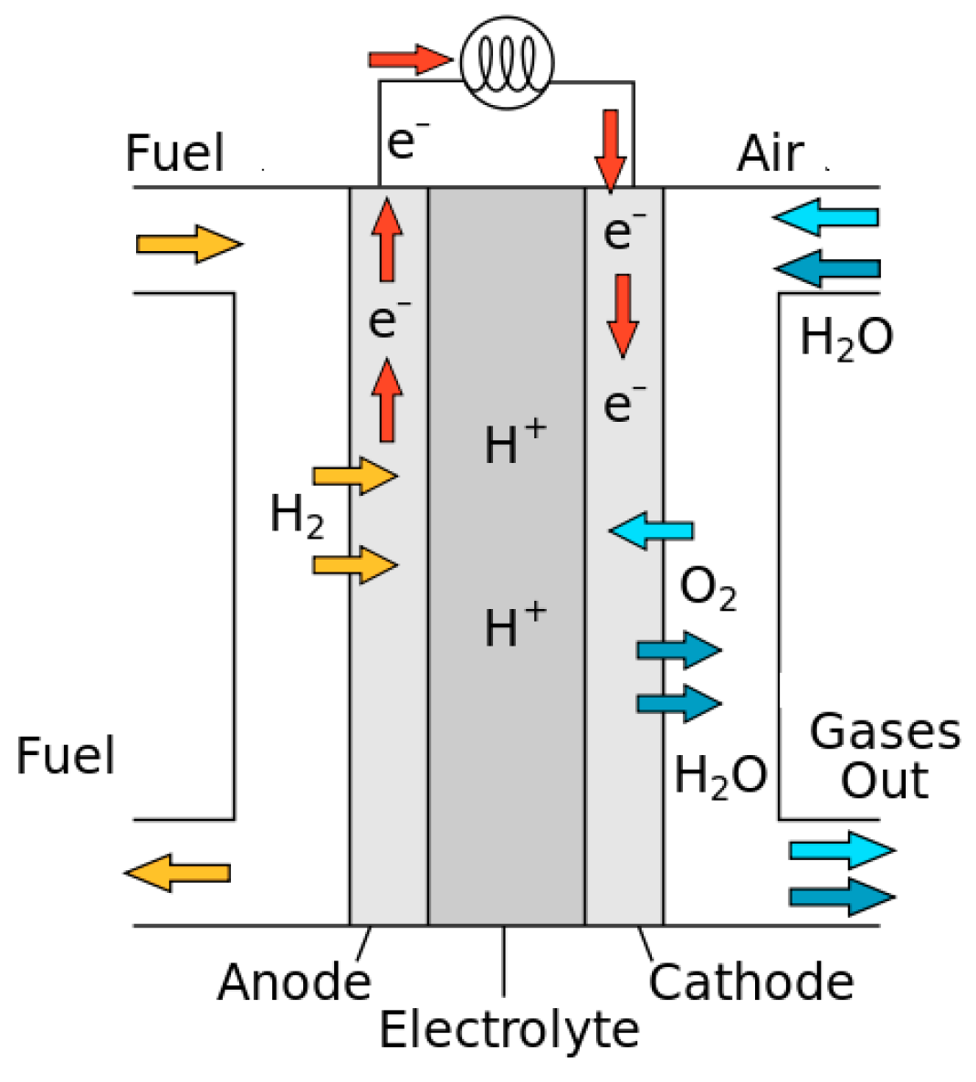
Figure 8.
EM Standard Torque/speed Characteristics.

Figure 9.
Typical Diesel Torque/Speed curve.

Figure 10.
Power Flows Through the Components.

Figure 11.
Forces and Torques Arrangement Due to the Contact Between Tire and Road.

Figure 12.
Behavior and Typical Values for the Rotational Inertia Coefficient, Ci [110].
Figure 12.
Behavior and Typical Values for the Rotational Inertia Coefficient, Ci [110].

Figure 13.
Example of Simulation Results Using Advisor. (a) simulations results; (b) vehicle input data.
Figure 13.
Example of Simulation Results Using Advisor. (a) simulations results; (b) vehicle input data.
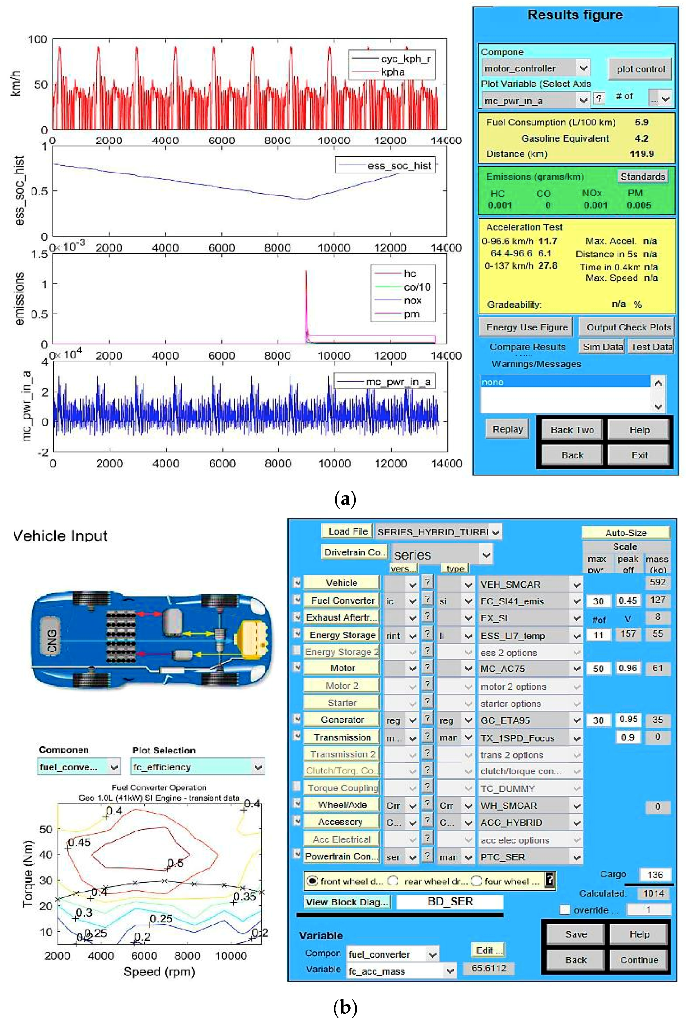
Figure 14.
Example of Components Packaging and Weight Distribution in a City Car.

Figure 15.
Example of Components Packaging and Weight Distribution for a Passenger Sedan.
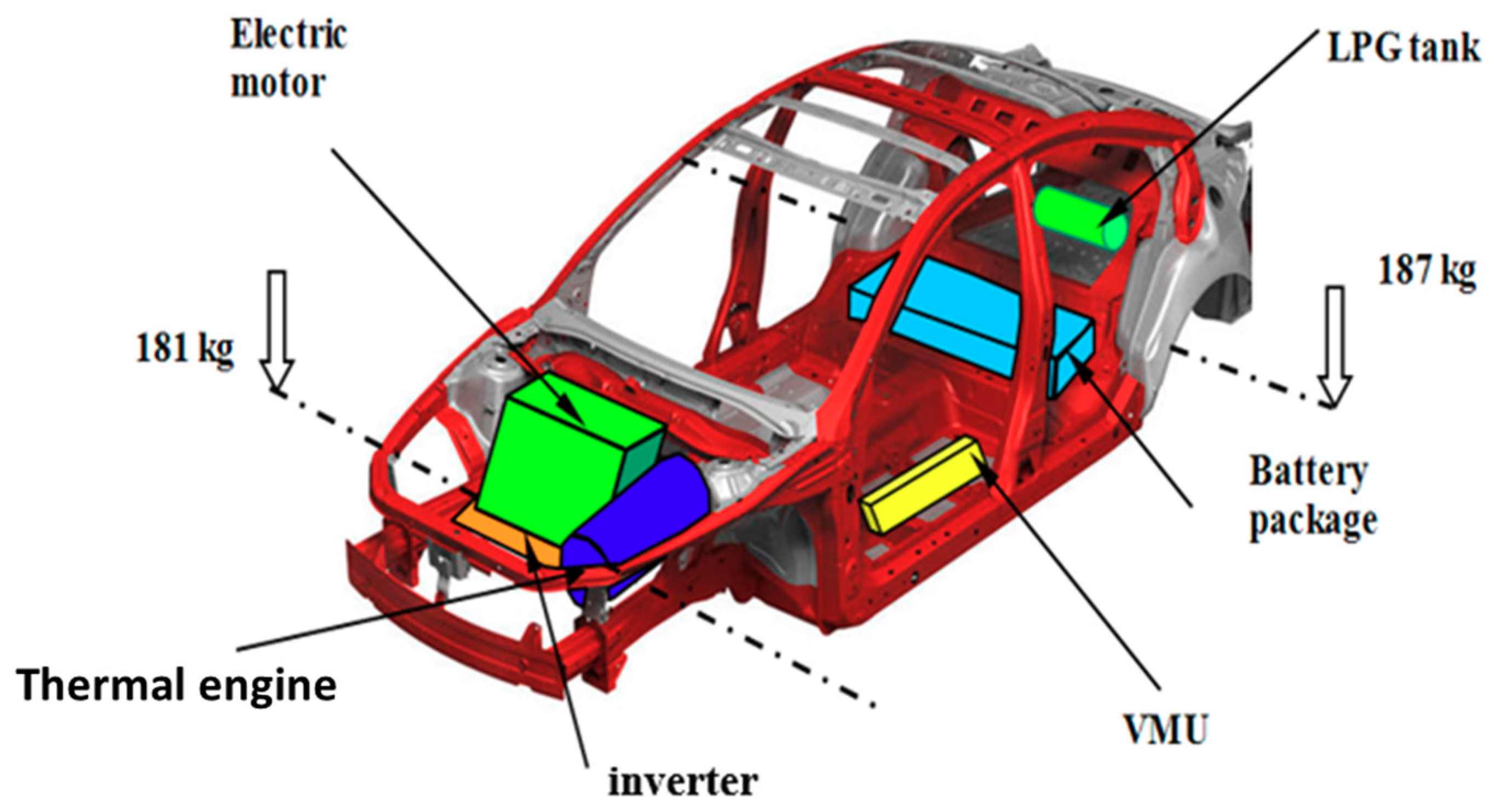
Figure 16.
Example of Components Packaging and Weight Distribution for an Extra-urban Bus.


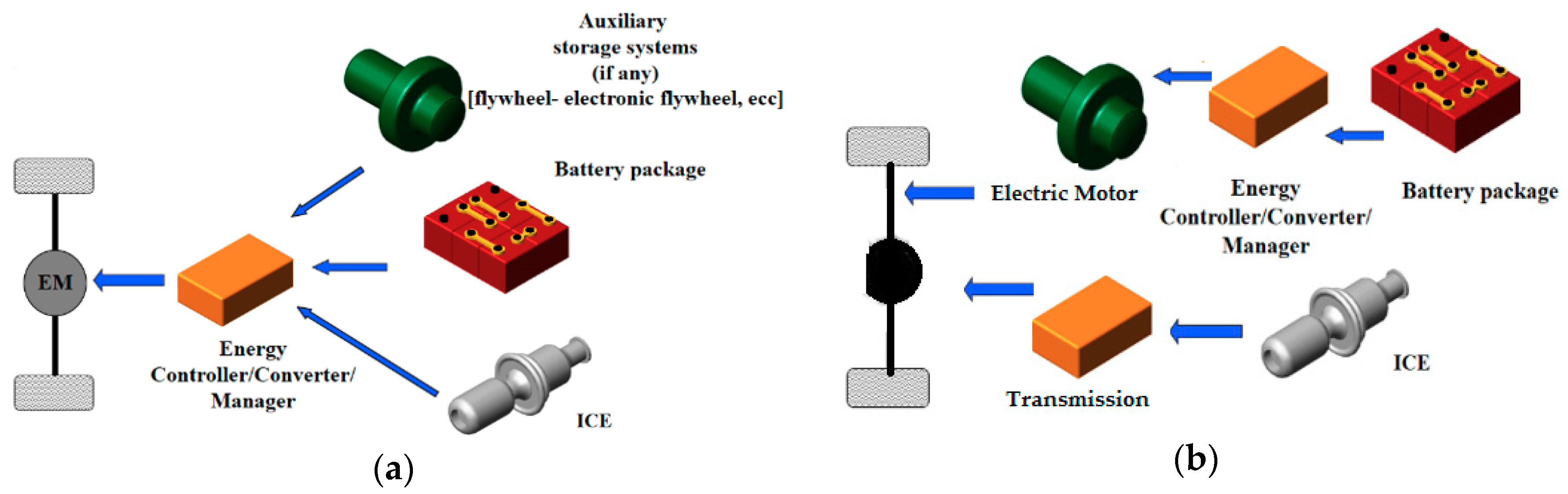
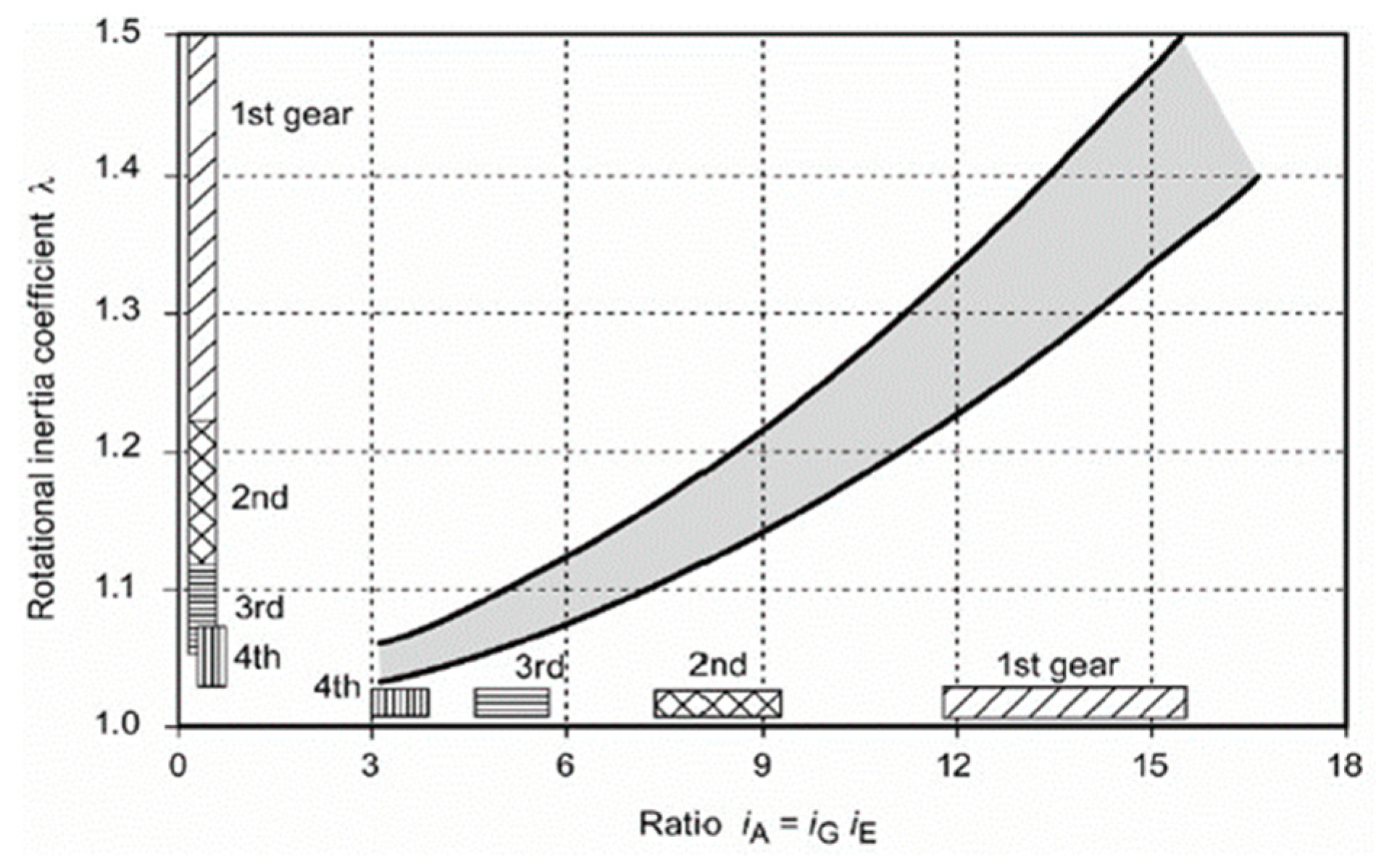
Table 1.
EURO Limit Percentages of Gaseous Emissions [g/km] [1].
Table 1.
EURO Limit Percentages of Gaseous Emissions [g/km] [1].
| Normative/Directive | Carbon Oxide CO | Hydrocarbons HC | Nitrogen Oxide NOx | Combined HC + NOx | Particulate Matter PM | ||||
|---|---|---|---|---|---|---|---|---|---|
| Gasoline | Diesel | Gasoline | Diesel | Gasoline | Diesel | Gasoline | Diesel | Diesel | |
| 91/441-1992 (EURO 1) | 2.72 | 2.72 | - | - | - | - | 0.97 | 0.97 | 0.14 |
| 94/12-1996 (EURO 2) | 2.20 | 1.00 | - | - | - | - | 0.50 | 0.70 | 0.08 |
| 98/69A-2000 (EURO 3) | 2.30 | 0.64 | 0.20 | - | 0.15 | 0.50 | - | 0.56 | 0.05 |
| 98/69B-2005 (EURO 4) | 1.00 | 0.50 | 0.10 | - | 0.8 | 0.25 | - | 0.30 | 0.025 |
| 715/2007-2011 (EURO 5) | 1.00 | 0.50 | 0.10 | - | 0.6 | 0.18 | - | 0.23 | 0.005 |
| 715/2007-2015 (EURO 6) | 1.00 | 0.50 | 0.10 | - | 0.6 | 08 | - | 0.17 | 0.005 |
| Systems Characteristics/Type of Vehicle | EV | HEV |
|---|---|---|
| Propulsion | Electric motors | Electric motor Thermal engine |
| Energy storage | Battery package Ultracapacitors | Battery package Ultracapacitors Fuel tank |
| Energy source infrastructure | Electric grid | Electric grid Commercial gas station |
| Characteristics | Zero emissions High efficiency Relatively short range Fuel independence High cost Commercial availability | Low emissions Relatively high fuel economy Extended range High cost Commercial availability Partial fossil fuel independence |
| Issues | Battery package overall dimensions and weight Battery MBTF Charging stationsCost | Battery package overall dimensions, weight, and management Energy fluxes control, management, and optimization |
| Features | Optimized power plant |
| Modular power plant possibilities | |
| Long operational life | |
| Excellent transient response | |
| Engine down sizing | |
| Advantageous packaging | |
| Possibility of Zero Emissions Operation Mode | |
| System complexity | |
| Drawbacks | Larger traction drive system |
| Multiple Energy conversions | |
| Optimized design of algorithms | |
| High investment cost | |
| Larger traction drive system | |
| Applications | City cars/passenger sedan/urban and extra urban bus |
| Features Drawbacks | Economic gain at high cost |
| Possibility of Zero Emissions Operation Mode | |
| System complexity | |
| Expensive system | |
| Complexity of control system | |
| Complex volume packaging | |
| Optimized design of algorithms | |
| High voltage required to improve efficiency | |
| Applications | Bus/heavy truck |
Table 5.
Battery Package Comparison [80].
Table 5.
Battery Package Comparison [80].
| Chemistry | Nominal Operative Voltage [V] N.O.V | Energy Density [Wh/kg] | Cycle Life | Self-Discharge Rate [%/Month] |
|---|---|---|---|---|
| Lead-Acid | 2 | 30–40 | 500–200 | 3–20 |
| Ni-Mh | 1.2 | 65–70 | 500–800 | 30 |
| Li-ion | 3.7 | 100–150 | 1000–1200 | 8 |
| LiPo | 3.7 | 130–200 | 800–1200 | 5 |
| LiFePO4 | 3.2 | 90–160 | 1500–3000 | <3 |
| LiTi | 2.3 | 70–100 | ≥4000 | <3 |
Table 6.
LiFePO4 Specifications [80].
Table 6.
LiFePO4 Specifications [80].
| Module Mass mmod | 19.1 kg |
| Module Voltage Vmod | 12.8 V |
| Cell Voltage Vcel | 3.2 V |
| Specific Power Psp | 201 W/kg |
| Specific Energy Esp | 67 Wh/kg |
| Battery Capacity C | 100 Ah |
| Maximum Current Cmax | 450 A |
Table 7.
Ultracapacitor Characteristics.
| Charging Time [s] | 0.3–30 |
| Discharging Time [s] | 0.3–30 |
| Energy Density [Wh/kg] | 1–10 |
| Power Density [W/kg] | <10,000 |
| MTBF | >500,000 |
| Efficiency [%] | 85–97 |
Table 8.
Flywheel Uses and Specifications [5].
Table 8.
Flywheel Uses and Specifications [5].
| Flywheel Purpose, Type | Geometric Shape Factor [k] | Mass [kg] | Diameter [m] | Angular Velocity [rpm] | Energy Store [MJ] | Energy Stored [kWh] | Energy Density [kWh/kg] |
|---|---|---|---|---|---|---|---|
| Small battery | 0.5 | 100 | 0.6 | 20,000 | 9.8 | 2.7 | 0.027 |
| Regenerative braking (trains) | 0.5 | 3000 | 0.5 | 8000 | 33 | 9.1 | 0.003 |
| Electric power backup | 0.5 | 600 | 0.5 | 30,000 | 92 | 26 | 0.043 |
Table 9.
Fuel Cell Specifications [84].
Table 9.
Fuel Cell Specifications [84].
| Characteristic | PEMFC | AFC | PAFC | MCFC | SOFC |
|---|---|---|---|---|---|
| Electrolyte | Perfluorosulfonic acid | Phosphoric acid | Phosphoric acid | Molten carbonate | Solid oxide |
| Design and structure | Simple | Simple | Simpler | Complex | Complex |
| Temperature range [°C] | 50 ÷ 100 | 80 ÷ 100 | 150 ÷ 200 | 600 ÷ 700 | 700 ÷ 1000 |
| Starting up time | Lower | Low | Low | High | Higher |
| Stack size [kW] | <1 ÷ 100 | 10 ÷ 100 | 100 ÷ 400 | 300 kW ÷ 3 MW <300 MW | 1 ÷ 2 MW |
| Sensitivity | More | Low | Low | Lower | Lower |
| Efficiency [%] | 40 ÷ 60 | 50 ÷ 60 | 40 ÷ 50 | 45 ÷ 60 | 50 ÷ 65 |
| Cell-life | 2 ÷ 10 μV/h | 0 ÷ 6 μV/h | 2 ÷ 4 μV/h | 5 μV/h | 0 ÷ 8 μV/h |
Table 10.
Energy Storage System Specifications.
| Characteristics | Battery | Ultracapacitor | Fuel Cell | Flywheel |
|---|---|---|---|---|
| Physics | Chemical | Electrostatic | Chemical | Mechanical |
| Technology | Proven | Promising | Promising | Proven |
| Energy density | High | Low | Very high | Low |
| Power density | Low | Very high | Medium | High |
| Charging time | Hours | Seconds | n.a. | Minutes |
| Discharging time | Hours | Seconds | n.a. | Minutes |
| MTBF | 3–5 years | > 10 years | 10,000–20,000 h | >20 years |
| Efficiency [%] | 75–85 | 85–95 | 40–60 | 80–90 |
| Environmental issue | Disposal | Low | Very low | Very low |
Table 11.
Electric Motors Classification.
| Commutator | No Commutator | ||
|---|---|---|---|
| Self ExcitedDC Motors | Separately Excited DC Motors | Induction Motors | Synchronous Motors |
| Series | PM excited | Cage rotor | PM motors |
| Shunt | Field excited | Wound rotor | SR motors |
Table 12.
EM Comparison.
| Characteristics | Commutator Motors | No Commutator Motors | ||
|---|---|---|---|---|
| Induction Motor | PM Motor | SR Motor | ||
| Controllability | 5 | 5 | 4 | 3 |
| Size and weight | 3 | 4 | 4.5 | 4 |
| Robustness | 3.5 | 5 | 4 | 4.5 |
| Reliability | 3 | 5 | 4 | 4.5 |
| Power density | 3 | 4 | 5 | 3.5 |
| Efficiency | 3 | 4 | 5 | 4.5 |
| Speed range | 2.5 | 4 | 5 | 5 |
| Life time | 3.5 | 5 | 4 | 4.5 |
| Torque density | 3 | 3.5 | 5 | 4 |
| Technical maturity | 5 | 4.5 | 4 | 3.5 |
| Cost | 3.5 | 5 | 3 | 4 |
| Over load capability | 3 | 4 | 4.5 | 4 |
| Torque ripple/noise | 3.5 | 4.5 | 4 | 3 |
| Manufacturability | 3 | 5 | 3 | 4 |
| Potential for improvements | 2.5 | 3 | 4.5 | 5 |
| City CAR Specifications | |
| Rolling radius | r = 0.25 m |
| Shape coefficient | f = 0.82 |
| Actual frontal section | Sf = 1.152 m2 |
| Drag coefficient | cx = 0.27 |
| Rolling coefficient | f = 0.015 |
| Vehicle mass | m = 980 kg |
| Equivalent vehicle mass | me = 1210 kg |
| Gravity | g = 9.81 m/s2 |
| Air density | ρ = 1.180 kg/m3 |
| Minimum SOC | 0.4 |
| Maximum SOC | 0.8 |
| SEDAN CAR Specifications | |
| Rolling radius | r = 0.25 m |
| Shape coefficient | f = 0.9 |
| Actual frontal section | Sf = 2.142 m2 |
| Drag coefficient | cx = 0.25 |
| Rolling coefficient | f = 0.015 |
| Vehicle mass | m = 1200 kg |
| Equivalent vehicle mass | me = 1240 kg |
| Gravity | g = 9.81 m/s2 |
| Air density | ρ = 1.180 kg/m3 |
| Minimum SOC | 0.6 (safety 0.4) |
| Maximum SOC | 0.8 |
| BUS Specifications | |
| Rolling radius | r = 0.46 m |
| Shape coefficient | f = 0.87 |
| Actual frontal section | Sf = 6.9 m2 |
| Drag coefficient | cx = 0.6 |
| Rolling coefficient | f = 0.018 |
| Vehicle mass | m = 7500 kg |
| Equivalent vehicle mass | me = 13300 kg |
| Gravity | g = 9.81 m/s2 |
| Air density | ρ = 1.180 kg/m3 |
| Minimum SOC | 0.42 |
| Maximum SOC | 0.8 |
© 2018 by the author. Licensee MDPI, Basel, Switzerland. This article is an open access article distributed under the terms and conditions of the Creative Commons Attribution (CC BY) license (http://creativecommons.org/licenses/by/4.0/).
Share and Cite
MDPI and ACS Style
Capata, R. Urban and Extra-Urban Hybrid Vehicles: A Technological Review. Energies 2018, 11, 2924. https://doi.org/10.3390/en11112924
AMA Style
Capata R. Urban and Extra-Urban Hybrid Vehicles: A Technological Review. Energies. 2018; 11(11):2924. https://doi.org/10.3390/en11112924
Chicago/Turabian StyleCapata, Roberto. 2018. "Urban and Extra-Urban Hybrid Vehicles: A Technological Review" Energies 11, no. 11: 2924. https://doi.org/10.3390/en11112924
Note that from the first issue of 2016, this journal uses article numbers instead of page numbers. See further details here.