Low-Voltage Ride-Through Operation of Grid-Connected Microgrid Using Consensus-Based Distributed Control


1
Department of Electrical Engineering, Incheon National University, Songdo-dong, 119 Academy-ro, Yeonsu-gu, Incheon 22012, Korea
2
Research Institute for Northeast Asian Super Grid, Incheon National University, 119 Academy-ro, Yeonsu-gu, Incheon 22012, Korea
*
Author to whom correspondence should be addressed.
Energies 2018, 11(11), 2867; https://doi.org/10.3390/en11112867
Submission received: 10 September 2018
/
Revised: 11 October 2018
/
Accepted: 19 October 2018
/
Published: 23 October 2018
(This article belongs to the Special Issue Control in Power Electronics)
Abstract
:Since the penetration of distributed energy resources (DERs) and energy storage systems (ESSs) into the microgrid (MG) system has increased significantly, the sudden disconnection of DERs and ESSs might affect the stability and reliability of the whole MG system. The low-voltage ride-through (LVRT) capability to maintain stable operation of the MG system should be considered. The main contribution of this study is to propose a distributed control, based on a dynamic consensus algorithm for LVRT operation of the MG system. The proposed control method is based on a hierarchical control that consists of primary and secondary layers. The primary layer is in charge of power regulation, while the secondary layer is responsible for the LVRT operation of the MG system. The droop controller is used in the primary layer to maintain power sharing among parallel-distributed generators in the MG system. The dynamic consensus algorithm is used in the secondary layer to control the accurate reactive power sharing and voltage restoration for LVRT operation. A comparison study on the proposed control method and centralized control method is presented in this study to show the effectiveness of the proposed controller. Different scenarios of communication failures are carried out to show the reliability of the proposed control method. The tested MG system and proposed controller are modeled in a MATLAB/Simulink environment to show the feasibility of the proposed control method.
1. Introduction
The AC microgrid (MG) system consists of inverter-based distributed generators (DGs), such as renewable energy resources and energy storage systems, which can operate in either islanded or grid-connected modes [1,2]. Although grid-connected operation of the MG system is the most economic operation, a disturbance from the utility grid such as fault or voltage sag might have a negative impact on the MG operation [3]. DGs could be disconnected from the MG system due to the disturbance from the utility grid. An additional reconnection process is required for these DGs after the disturbance. The sudden disconnection of DGs could affect to the stability and reliability of the MG system [4,5]. Low voltage ride through (LVRT) operation strategy of the MG system should be considered to improve the system stability and reliability [6,7,8,9].
Conventionally, external devices were installed in the MG system to improve the LVRT capability [10,11,12,13,14]. In [11], the distribution static synchronous compensator (DSTATCOM) is used for supplying additional reactive power to compensate for the voltage drop. The dynamic voltage restorer (DVR) is also used in the MG system to improve the LVRT capability [12]. In case of using DVR, the series transformer, converter, and energy storage system are usually required. In [13], a comparison of superconducting fault current limiter (SFCL) and DVR for LVRT improvement was presented. It was shown that the use of SFCL showed better control effects on power stabilization. In [14], the SFLC and superconducting magnetic energy storage (SMES) were combined to improve the system voltage during disturbance. However, these LVRT strategies are costly due to the installation of additional devices.
Since the use of inverter-based DGs in MG systems has increased significantly, the controllers of such DGs could be designed properly for the LVRT operation. An improved control scheme of virtual synchronous generator (VSG) was proposed in [15] for LVRT operation of the MG system. A DG controller with smooth switching between proportional-resonance (PR) current control and VSG was used to improve the LVRT operation of the MG system [16]. The fuzzy neural network controllers were proposed in [17,18] to control reactive power during voltage sag. However, these studies did not deal with the parallel operation of DGs during voltage sag. The accurate reactive power sharing among DGs during voltage sag was not mentioned. The DG controller with different droop gains was proposed for the islanded MG system [19]. Although reactive power sharing among parallel DGs was considered in this study, the grid-connected operation of the MG system is not considered. DGs controllers with the vector control technique based on sequence components of voltage have been proposed for LVRT operation. The positive/negative sequences current injection methods were proposed in [20,21] to limit overcurrent during LVRT operation. However, the control strategies based on sequence components are complex since they required the extraction of the negative and positive sequences. To overcome the problem, a centralized control method for LVRT operation was proposed in [22]. The voltages at point of common coupling (PCC) and grid are measured and sent to a central controller. The control actions generated from a central controller were delivered to each DG in the MG system. This centralized control scheme has low reliability since the controllers of all DGs rely on a central controller. Communication failure could have a significant impact on the control performance of the centralized controller. In addition, the performance of reactive power sharing during voltage sag was not mentioned in this study. In order to address the problem, this study proposes a distributed control method based on a dynamic consensus algorithm for LVRT operation of the MG system. The main contributions of this study are as follows:
- ▪
- The injected reactive power of DG during voltage sag should be proportional to the DG rating. Existing controllers for LVRT operation of the MG system focused only on the voltage restoration during voltage sag whereas the accurate reactive power sharing was not considered. This study proposes a distributed control, considering both voltage restoration and accurate reactive power sharing during voltage sag.
- ▪
- The reliability of the controller is an important aspect of the LVRT operation of the MG system. In the centralized control method, the reliability of the controller is significantly affected by the communication failure. The proposed controller could improve the reliability of the controller by the use of distributed control based on dynamic consensus algorithm.
The proposed control method is based on hierarchical control that consists of the primary layer with droop control for power sharing and the secondary layer with reactive power and voltage control. The dynamic consensus algorithm was used in the secondary control layer to find the average value of output reactive power and output voltage between DGs in the MG system. Reactive power required for voltage compensation during voltage sag was calculated from the secondary control layer. With the reactive and voltage control in the secondary layer, the proposed controller could maintain accurate reactive power sharing and restore the system voltage during voltage sag. A comparison study on the proposed distributed control and the centralized control in [22] is presented in this study to show the effectiveness of the proposed method. Several scenarios of communication failures were carried out to show the reliability of the proposed distributed control compared to the centralized control.
The rest of this paper is organized as follows: Section 2 discusses LVRT operation of the MG system. Section 3 presents a proposed LVRT control system with a two-level hierarchy consisting of primary and secondary controllers. Section 4 presents the simulation results and comparison. Finally, the main conclusions of this study are summarized in Section 5.
2. LVRT Operation of Microgrid System
Voltage sag during fault has an impact on transient performance of DGs and reliability of power supply. DGs might be enforced to trip off during fault for safety operation, which results in many adverse effects on system stability and reliability. Any sudden disconnection of DG or MG from utility grid should be avoided. Thus, the development of MG system should consider LVRT capability to improve their stability and reliability. To meet the requirement of LVRT, DGs should inject reactive power to improve the grid voltage during voltage sag.
For example, it was recommended in [23] that if the system voltage drops to no less than 0.3 pu for 0.5 s, and then if it gradually recovers to 90% of nominal grid voltage (Vg) within at most 1.5 s, that is, it stays above the red curve in Figure 1, then the DG should stay connected. DGs were allowed to disconnect if the grid voltage falls below the red curve. Otherwise, DGs should supply a certain amount of reactive power, as shown in Figure 2. If the grid voltage dropped to 20%, a 1% drop of the grid voltage required at least a k% increase of reactive power, where k is the slope constant. The slope constant k could be adjusted to determine the required reactive power according to the drop voltage, which depended on the grid codes of each country. For example, the slope constant k in Australia is 4, whereas it is 2 in Denmark and Germany [24]. In the MG system, it is recommended that the slope constant k should be greater than 6 [25,26,27]. If the grid voltage drops to higher than 50%, DGs should supply maximum reactive power (Qmax) and DGs should be disconnected if the reduction of grid voltage is higher than 70%.
3. Proposed Control Strategy
It was shown in Section 2 that DG should inject reactive power to recover system voltage during a voltage sag. In this paper, a distributed control of DG for LVRT operation of the MG system is proposed. An overall control diagram of DG is shown in Figure 3, which is based on hierarchical control scheme with primary and secondary layers. The primary control is in charge of power regulation while the secondary control is responsible for the voltage restoration. The droop control was used in the primary control layer to maintain power sharing among DGs. The dynamic consensus algorithm was used in the secondary control layer to control reactive power and system voltage.
In the proposed controller shown in Figure 3, voltage and current measurements (vc and io) were used to calculate the active and reactive power for the power control loop. The active and reactive power references (Pref and Qref) were used for the droop controller in the primary control loop. The secondary control loop uses the average value of voltage and reactive power (Vavg and Qavg) to calculate the required reactive power (Qadj) to recover the grid voltage during disturbance. An output filter with an inductor (Lf) and capacitor (Cf) was used in the converter.
3.1. Primary Control
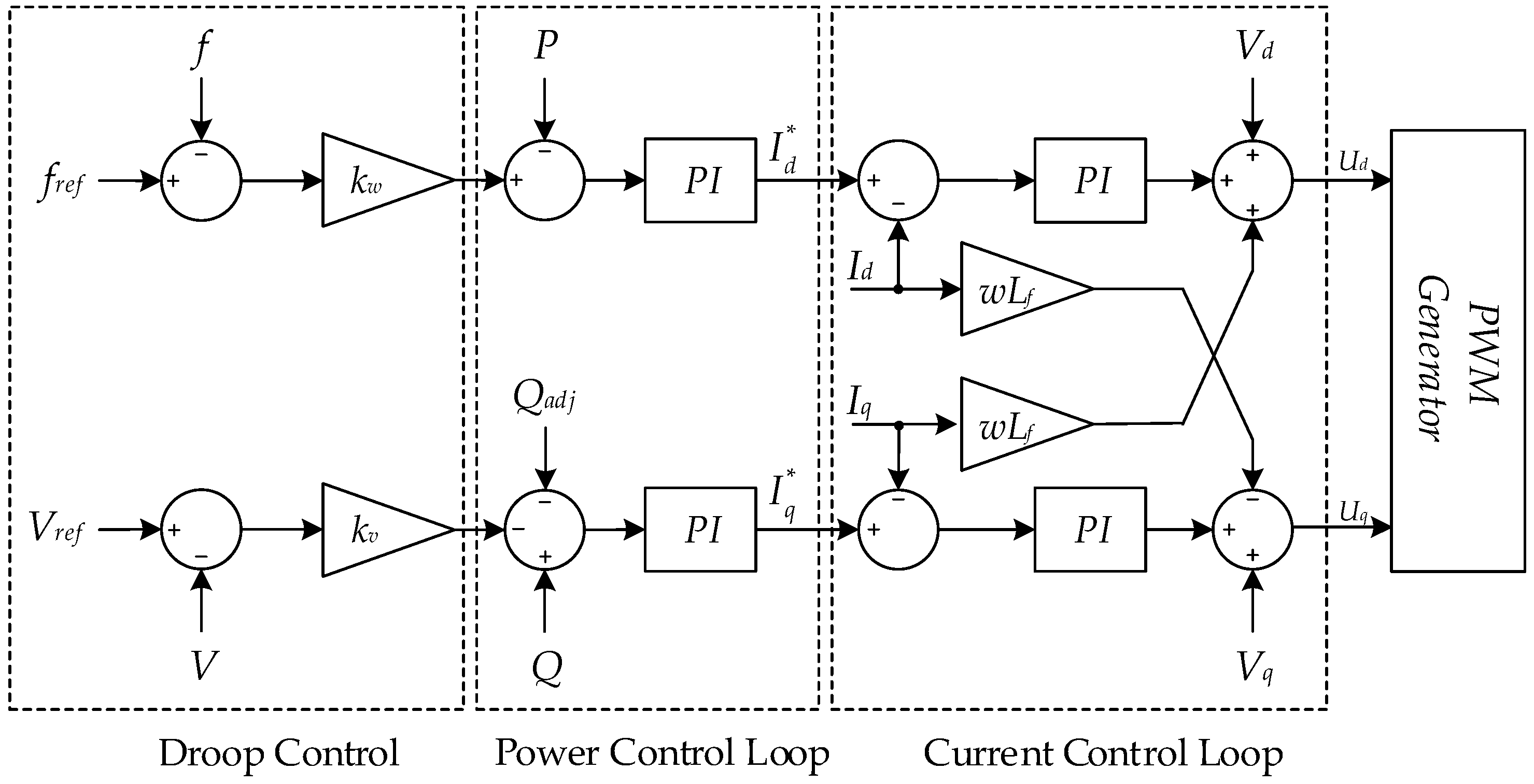
The voltage-source-converter (VSC) with the current control mode was used in this study. The VSC controller is implemented in rotating dq reference frames with the proportional-integral (PI) control technique. The primary control layer consists of power and current control loops. The active power/frequency and reactive power/voltage droop control were used to maintain active and reactive power sharing among parallel DGs. The control diagram of the power and current control loops is shown in Figure 4.
The current control loop was based on the decoupling control method, in which the current references ( and ) were generated from the power control loop, as shown in Equations (1) and (2):
where and represent the proportional and integral coefficient of power control; P and Q are the measured active and reactive powers, respectively; fref and Vref represent the reference frequency and voltage, respectively; f and V are the measured frequency and voltage, respectively; kw and kv represent the frequency and voltage droop coefficients, respectively.
The reference currents are sent to the current loop to generate the reference voltage (Ud, Uq), as shown in Equations (3) and (4):
where and represent the proportional and integral gains of current control loop; Vd and Vq are the dq components of the measured voltage; Id and Iq are the dq components of the measured current; ω is the measured angular frequency of the MG system.
3.2. Secondary LVRT Control
The dynamic consensus algorithm was used in the secondary control layer to achieve accurate reactive power sharing and voltage restoration during voltage sag. The control diagram of the secondary control layer is shown in Figure 5. The communication network was used to exchange information among DGs. The dynamic consensus algorithm was used to find the average values of reactive power and voltage among DGs. The PI regulators were used to control reactive power and voltage with the references obtained from the dynamic consensus algorithm.
In Figure 5, QC and QL are the reactive power injections from the consensus algorithm and the requirement of voltage support. The reactive power QL was determined according to the requirements of voltage support graph in Figure 2; it can be expressed as follows:
where Vg0 and Vg are grid voltages before and after sag, respectively, and Qmax is the converter maximum power capacity.
The injected reactive power QL was calculated by Equation (5). When the grid voltage (Vg) dropped to higher than 0.5 pu, the maximum reactive power Qmax was injected to compensate for voltage drop. If the grid voltage Vg was in the dead band (from 0.8 pu to 1.1 pu), the injected reactive power QL was equal zero. Otherwise, reactive power QL was determined by the multiply of k gain and the drop voltage [25,26,27].
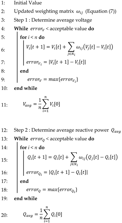
The reactive power QC was used to maintain accurate reactive power sharing and restore system voltage, which was calculated by the dynamic consensus algorithm. The consensus algorithm was used to compute the average values of reactive power and voltage among DGs. Each DG can be considered as one node in the communication network. Each node carries out its updates at each step based on local state and communication with the neighbors [28]. Network topology of DG is represented using undirected connected graph with nodes set and edge . The neighbors of i-DG are denoted by . The linear iterative algorithm for updating information in all n DG is as follows:
where t is the discrete time index; is information to be exchanged with each DGi such as Qi and Vi; is the information of the adjacent nodes; j is the index of adjacent DG of node i; is weight of consensus algorithm; Ni is the set of nodes that connects to node i; n is the total number of nodes.
The weight matrix depends on the network topology. In this study, the ring connection was used for communication network and the design of the weight matrix was based on the metropolis method. It is suitable for distributed control by flexibly responding to system changes [29]. The design of the weighting matrix is based on metropolis method, as given by (7):
where and is the elements of the Laplacian matrix L.
Final output of consensus algorithm is found by repeating the calculation of Equation (6) with t = ∞, as shown in (8):
The metropolis method requires the degree of the i and j DG when the weight matrix updates. Since the weight matrix was recalculated according to the change of network topology, it can be continuously controlled, even if communication between DG fails. Therefore, in the secondary controller, the injected reactive power was generated through PI controller by receiving the average voltage and reactive power from the communication block. The injected reactive power QC is given by:
where and represent proportional and integral coefficients of secondary controller; Vavg and Qavg are the average values of voltage and reactive power, which are calculated from the consensus algorithm; Vref is the reference voltage.
Required reactive power Qadj shown in (10) consists of two terms: compensated reactive power for accurate reactive power sharing (QC) and required reactive power to compensate for the voltage sag. As a result, the proposed controller can restore the system voltage while maintaining accurate reactive power sharing during voltage sag.
4. Simulation Results
The tested MG system shown in Figure 6 was used to validate the proposed controller. Four DGs based on the current source inverter supply power to the local load. The droop controller was used in the primary control level to share power among four DGs. The secondary controller was based on proposed distributed control for LVRT operation of the MG system. Network communication with ring topology is used in this study. The Laplacian matrix of communication network is as follows:
Substituting Laplacian matrix from Equation (11) in Equations (7), the weighting matrix can be determined as follows:
The communication rate was considered as 5 ms, which was modeled by a block of “zero-order hold” in Simulink. Popular communication protocol such as transmission control protocol/internet protocol (TCP/IP) could be used for the proposed controller. Since this study mainly focuses on the control algorithm for the LVRT operation of the MG system, detailed modeling of communication protocol of the secondary controller was neglected for the sake of simplicity.
The system parameters are shown in Table 1. The tested MG system and proposed controller was modeled in a MATLAB/Simulink (R2011b, MathWorks, Natick, MA, USA) environment. The consensus algorithm shown in Algorithm 1 was implemented by the user-defined function in MATLAB/Simulink. In order to verify the proposed distributed LVRT method, three cases considering communication failure were studied.
| Algorithm 1: Consensus algorithm |
 |
4.1. LVRT Operation of the MG System
This section shows the effect of the proposed control on the LVRT operation of the MG system. A comparison study on the proposed controller and the centralized control in [20] is presented. In case of a centralized controller, a central controller measures the voltage at point of common coupling (PCC) then the control actions are delivered to each DG. It is assumed that the voltage sag with 30% drop occurs from 3 s to 4 s due to the sudden inductive load change in the utility grid.
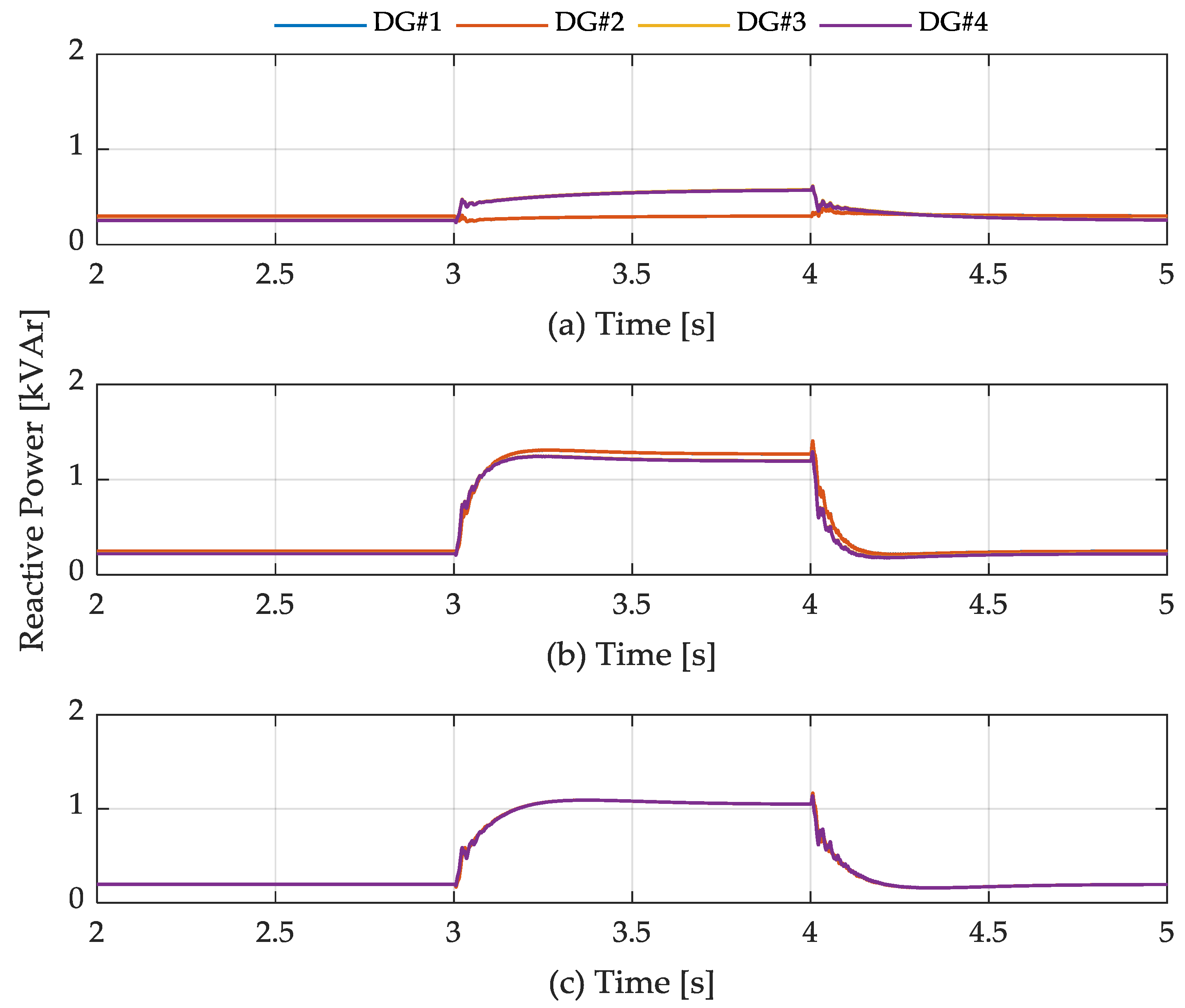
Figure 7 shows the output voltage of four DGs during voltage sag. Without the LVRT function shown in Figure 7a, the output voltages of DGs dropped to 0.7 pu during the grid voltage sag. With the LVRT function, the reactive power was injected by four DGs to compensate for the voltage drop, as shown in Figure 8. The system voltage recovered to the nominal values with the LVRT function, as shown in Figure 7b,c. The terminal voltage of each DG was the same due to the controllers. In the centralized control method, the output voltage of each DG was controlled to follow the PCC voltage. By comparison, in the proposed controller, the output DG voltage was controlled to follow the average voltage of all DGs. It can be seen that for both proposed control and centralized control, the reactive power was injected to recover the system voltage. However, while the injected reactive power of four DGs was slight different with the centralized control, the proposed control could maintain equal reactive power sharing among four DGs.
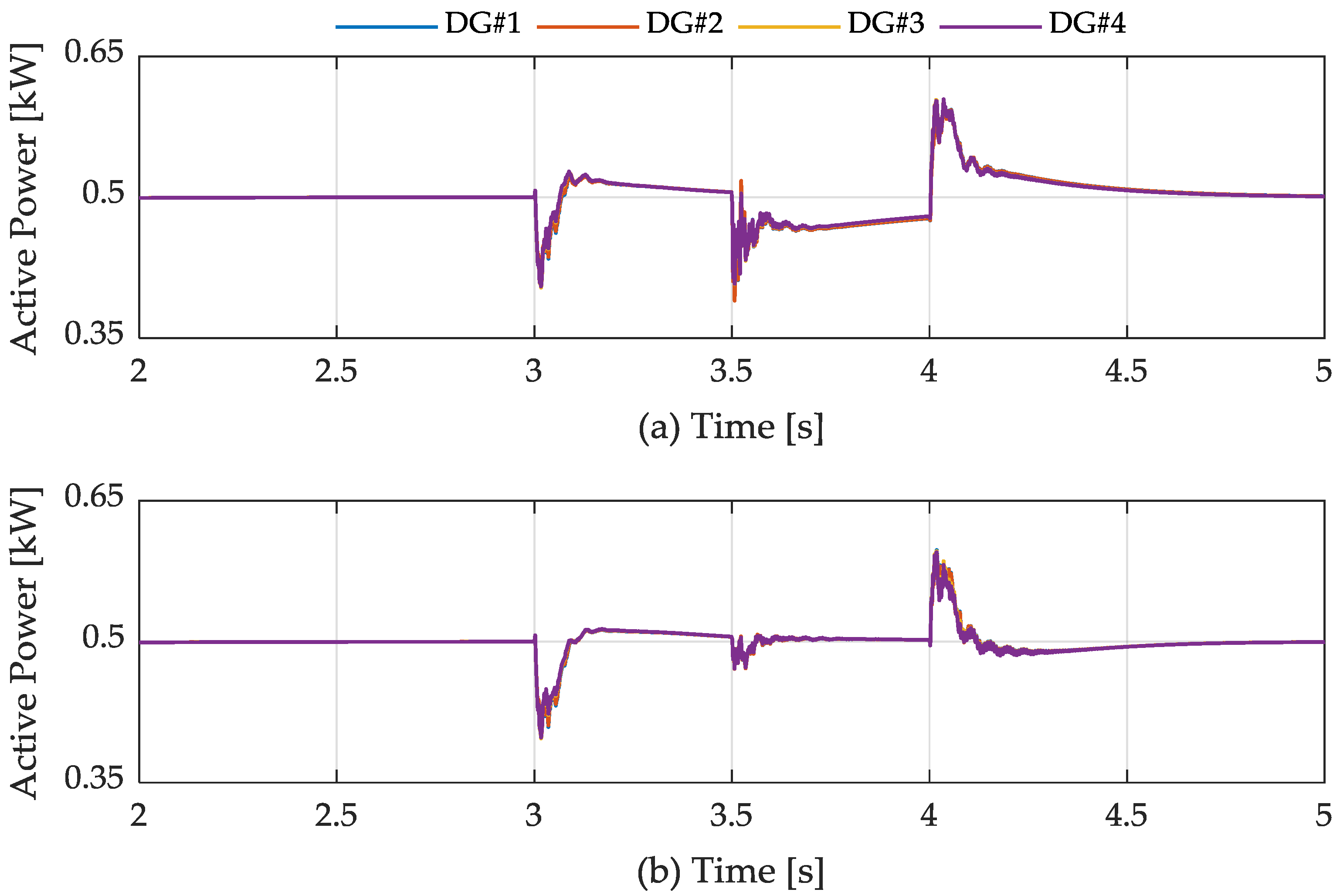
Figure 9 shows the output currents of four DGs. In case of proposed control, the rising current due to reactive power injection was less than twice the rated current. However, with the centralized controller, the injected current during voltage sag was twice as high compared to rated current. Figure 10 shows the active power output of four DGs. It can be observed that the active power outputs of the four DGs were shared equally, even though the voltage sag occurs.
4.2. Communication Failure from DG
In this section, the effectiveness of the distributed control over the centralized control is presented. It is assumed that the communication link between the centralized controller and the DG1 failed in the centralized control method. With the proposed controller, the communication link between DG1 and DG2 was assumed to have failed. The communication topology of the proposed method has been changed from the ring topology to the line topology. The dynamic consensus algorithm was adjusted according to the communication topology of the proposed method. The three-phase grid voltage sag started from 3 s to 4 s; the communication failed at 3.5 s.
Figure 11 shows the output voltage of four DGs in case of centralized and proposed methods. Compared to the proposed control method, it can be seen that the communication failure had a significant impact to the centralized controller. The control signal from the central controller cannot deliver to DG2, which causes the transient in the output voltage of four DGs, as shown in Figure 11a. By comparison, with the proposed method based on distributed control in Figure 11b, the dynamic consensus algorithm was adjusted accordingly to find the agreement between four DGs even though the communication between DG1 and DG2 was disconnected.
Figure 12 shows the reactive power sharing among four DGs during the voltage sag. In case of centralized controller, when the communication failure occurs, the reactive power output of DG2 reduces significantly while the reactive power output of other DGs increases. It can be seen the inaccurate reactive power sharing among four DGs when the centralized controller was used for the LVRT operation. The problem of inaccurate reactive power sharing is solved by using the proposed method. Although the communication failure between two DGs occurs, four DGs share reactive power equally.
Figure 13 shows the output current of four DGs with the centralized and proposed control methods. In case of centralized control, the reduction of output current in DG2 results in the increase of output current of other DGs, which might cause the stress on the power semiconductor. By comparison, the proposed control still maintains output current of four DGs equally, as shown in Figure 13b. Figure 14 shows the active power sharing among four DGs. It can be seen that the proposed method showed a superior performance compared to the centralized control.
4.3. Communication Failure from the PCC Voltage Measurement
For LVRT operation of the centralized method, the PCC voltage was measured and used for generating reactive power. Therefore, communication failure from the PCC voltage measurement has a negative impact on control performance of the MG system. This section examines the effect of communication failure from the PCC voltage measurement on the control performance of proposed method and centralized method. The three-phase grid voltage sag started from 3 s to 4 s and the communication failed at 3.5 s at the PCC stage.
Figure 15 shows the comparison of output voltage of four DGs with proposed method and centralized method. It can be observed that the communication failure from the PCC voltage measurement had a significant impact on the control performance of the centralized method. Four DGs loss the PCC voltage information, which results in the significant drop of output voltage as shown in Figure 15a. By comparison, the proposed method still maintains the system voltage at the nominal value although the communication failure from the PCC voltage measurement occurs.
The injected reactive power of four DGs during communication failure is shown in Figure 16. With the centralized controller, four DGs reduced reactive power output when the communication failure occurred, which resulted in the drop of system voltage shown in Figure 16a. By comparison, the proposed control can stably inject reactive power during communication failure to compensate for the voltage sag. In addition, the reactive power of the four DGs is still shared equally, although the communication failure occurs.
Figure 17 shows the output currents of four DGs and Figure 18 shows the output active power of four DGs. With the centralized method, the output current and power of four DGs were reduced. However, the proposed method can maintain output power and current of four DGs. It can be observed that the proposed control method showed a superior performance over the centralized control method.
5. Conclusions
This paper proposed a distributed control of DG based on dynamic consensus algorithm to improve the LVRT capability of the MG system. The proposed control method was based on a hierarchical control that consisted of a primary layer with droop control and a secondary layer with the LVRT function. Based on the dynamic consensus algorithm, the secondary controller calculated the injected reactive power to recover the output DG voltage during voltage sag while maintaining the accurate reactive power sharing. A comparison study on the proposed control method and the centralized method was presented in this study to show the effectiveness of the proposed control. In the centralized method, the main function of the centralized controller was to recover the terminal voltage of each DG according to the PCC voltage. Thus, although the reactive power sharing among DGs was equal in normal operation, it was not equal when the system voltage was restored during the voltage sag. The problem was improved by using the proposed control method that could restore the system voltage to the nominal value and maintain accurate reactive power sharing. The simulation results showed that the communication failures had a significant impact on the LVRT operation of the MG system with the centralized method. DG with the loss of communication link could not support the reactive power to recover the voltage during the voltage sag. Especially in the case of communication failure from the PCC voltage measurement, all DGs failed to recover the terminal voltage of each DG during voltage sag. With the proposed method based on distributed control, the communication failures had a slight impact on the LVRT operation of the MG system. Although the communication failures occur in either the DG side or PCC, all DGs maintained stable reactive power support to recover the terminal voltage of each DG during voltage sag. The reliability of the control system with the proposed distributed control for LVRT operation was improved. It was observed that the proposed distributed control method showed better performance than the centralized method through several case studies.
Author Contributions
Theoretical analysis, modeling, and manuscript preparation, W.-G.L.; Simulation, T.-T.N.; Verified the analytical methods, H.-J.Y.; Manuscript revision, H.-M.K.
Funding
This work was supported by the Korea Institute of Energy Technology Evaluation and Planning (KETEP) and the Ministry of Trade, Industry & Energy (MOTIE) of the Republic of Korea (No. 20168530050030).
Acknowledgments
This work was supported by the Korea Institute of Energy Technology Evaluation and Planning (KETEP) and the Ministry of Trade, Industry & Energy (MOTIE) of the Republic of Korea (No. 20168530050030).
Conflicts of Interest
The authors declare no conflict of interest.
References
- Hossain, M.A.; Pota, H.R.; Hossain, M.J. Overview of AC Microgrid Controls with Inverter-Interfaced Generations. Energies 2017, 10, 1300. [Google Scholar] [CrossRef]
- Ates, Y.; Boynuegri, A.R.; Uzunoglu, M.; Nadar, A.; Yumurtaci, R.; Erdinc, O.; Paterakis, N.G.; Catalao, J.P.S. Adaptive Protection Scheme for a Distribution System Considering Grid-Connected and Islanded Modes of Operation. Energies 2016, 9, 378. [Google Scholar] [CrossRef]
- Zhang, W.; Rocabert, J.; Candela, J.I.; Rodriguez, P. Synchronous Power Control of Grid-Connected Power Converters under Asymmetrical Grid Fault. Energies 2017, 10, 950. [Google Scholar] [CrossRef]
- Duong, M.Q.; Leva, S.; Mussetta, M.; Le, K.H. A Comparative Study on Controller for Improving Transient Stability of DFIG Wind Turbines during Large Disturbances. Energies 2018, 11, 480. [Google Scholar] [CrossRef]
- Lu, X.; Wang, J.; Guerrero, J.M.; Zhao, D. Virtual-Impedance-Based Fault Current Limiters for Inverter Dominated AC Microgrids. IEEE Trans. Smart Grid 2018, 9, 1599–1612. [Google Scholar] [CrossRef] [Green Version]
- Tsili, M.; Papathanassiou, S. A Review of Grid Code Technical Requirements for Wind Farms. IET Renew. Power Gener. 2009, 3, 308–332. [Google Scholar] [CrossRef]
- Jaalam, N.; Rahim, N.A.; Bakar, A.H.B.A.; Mouneir, B. Strategy to Enhance the Low-Voltage Ride- through in Photovoltaic System During Multi-Mode Transition. Sol. Energy 2017, 154, 744–754. [Google Scholar] [CrossRef]
- Akhlaghi, S.; Sarailoo, M.; Akhlaghi, A.; Ghadimi, A.A. A Novel Hybrid Approach Using SMS and ROCOF for Islanding Detection of Inverter-based DGs. In Proceedings of the IEEE Power and Energy Conference at Illinois (PECI), Champaign, IL, USA, 23–24 February 2017. [Google Scholar]
- Akhlaghi, S.; Ghadimi, A.A.; Akhlaghi, A. A Novel Hybrid Islanding Detection Method Combination of SMS and Q-f for Islanding Detection of Inverter-based DG. In Proceedings of the Power and Energy Conference at Illinois (PECI), Champaign, IL, USA, 28 February–1 March 2014. [Google Scholar]
- Dehnavi, S.D.; Shayani, E. Compensation of Voltage Disturbances in Hybrid AC/DC Microgrids Using Series Converter. Ciênc. Nat. 2015, 37, 349–356. [Google Scholar] [CrossRef]
- Jayawardena, A.V.; Meegahapola, L.G.; Robinson, D.A.; Perera, S. Low-voltage ride-through characteristics of microgrids with distribution static synchronous compensator (DSTATCOM). In Proceedings of the Australasian Universities Power Engineering Conference (AUPEC), Wollongong, Australia, 27–30 September 2015. [Google Scholar]
- Omar, R.; Rahim, N.A. Power Quality Improvement in Low Voltage Distribution System Using Dynamic Voltage Restorer (DVR). In Proceedings of the 5th IEEE Conference on Industrial Electronics and Applications, Taichung, Taiwan, 15–17 June 2010. [Google Scholar]
- Chen, L.; Chen, H.; Yang, J.; Zhu, L.; Tang, Y.; Koh, L.H.; Xu, Y.; Zhang, C.; Liao, Y.; Ren, L. Comparison of Superconducting Fault Current Limiter and Dynamic Voltage Restorer for LVRT Improvement of High Penetration Microgrid. IEEE Trans. Appl. Supercond. 2017, 27, 1–7. [Google Scholar] [CrossRef]
- Chen, L.; He, H.; Zhu, L.; Guo, F.; Shu, Z.; Shi, X.; Yang, J. Coordinated Control of SFCL and SMES for Transient Performance Improvement of Microgrid with Multiple DG Units. Can. J. Electr. Comput. Eng. 2016, 37, 158–167. [Google Scholar] [CrossRef]
- Aplipoor, J.; Miura, Y.; Ise, T. Voltage sag ride-through Performance of Virtual Synchronous Generator. In Proceedings of the International Power Electronics Conference (IPEC), Hiroshima, Japan, 18–21 May 2014. [Google Scholar]
- Shi, K.; Song, W.; Xu, P.; Liu, R.; Fang, Z.; Ji, Y. Low-Voltage Ride-Through Control Strategy for a Virtual Synchronous Generator Based on Smooth Switching. IEEE Access 2017, 6, 2703–2711. [Google Scholar] [CrossRef]
- Lin, F.J.; Lu, K.C.; Yang, B.H. Recurrent Fuzzy Cerebellar Model Articulation Neural Network Based Power Control of a Single-Stage Three-Phase Grid-connected Photovoltaic System during Grid Faults. IEEE Trans. Ind. Electron. 2017, 64, 1258–1268. [Google Scholar] [CrossRef]
- Lin, F.J.; Lu, K.C.; Ke, T.H. Probabilistic Wavelet Fuzzy Neural Network based reactive power control for grid-connected three-phase PV system during grid faults. Renew. Energy 2016, 92, 437–449. [Google Scholar] [CrossRef]
- Rajamand, S.; Ketabi, A.; Zahedi, A. A New LVRT Strategy for DGs with Different Droop Gains in Islanded Microgrid with Various Loads. EPE J. 2018, 28, 1–12. [Google Scholar] [CrossRef]
- Lee, C.T.; Hsu, C.W.; Cheng, P.T. A Low-Voltage Ride-Through Technique for Grid-Connected Converters of Distributed Energy Resources. IEEE Trans. Ind. Appl. 2011, 47, 1821–1832. [Google Scholar] [CrossRef]
- Zhao, X.; Guerrero, J.M.; Savaghebi, M.; Vasquez, J.C.; Wu, X.; Sun, K. Low-Voltage Ride-Through Operation of Power Converters in Grid-Interactive Microgrids by Using Negative-Sequence Droop Control. IEEE Trans. Power Electron. 2016, 31, 3128–3142. [Google Scholar] [CrossRef]
- Sadeghkhani, I.; Golshan, M.E.H.; Sani, A.M.; Guerrero, J.M. Low-voltage ride-through of a Droop-based Three-phase Four-wire Grid-connected Microgrid. IET Gener. Trans. Distrib. 2018, 12, 1906–1914. [Google Scholar] [CrossRef]
- Liu, X.; Xu, Z.; Wong, K.P. Recent Advancement on Technical Requirements for Grid Integration of Wind Power. Mod. Power Syst. Clean Energy 2013, 1, 216–222. [Google Scholar] [CrossRef]
- Mohseni, M.; Islam, S.M. Review of International Grid Codes for Wind Power Integration: Diversity, technology and a case for global standard. Renew. Sustain. Energy Rev. 2012, 16, 3876–3890. [Google Scholar] [CrossRef]
- Kish, G.J.; Lehn, P.W. Microgrid Design Considerations for Next Generation Grid Codes. In Proceedings of the IEEE Power and Energy Society General Meeting, San Diego, CA, USA, 22–26 July 2012. [Google Scholar]
- Erlich, I.; Bachmann, U. Grid Code Requirements Concerning Connection and Operation of Wind Turbines in Germany. In Proceedings of the IEEE Power Engineering Society General Meeting, San Francisco, CA, USA, 16 June 2005. [Google Scholar]
- Ruitenbeek, E.V.; Boemer, J.C.; Skaloumpakas, K.; Torres, J.L.R.; Gibescu, M.; Mart, A.M.M.; Meijden, M.A.M.M. A Proposal for New Requirements for the Fault Behaviour of Distributed Generation Connected to Low Voltage Networks. In Proceedings of the 4th Solar Integration Workshop, Berlin, Germany, 10–11 November 2014. [Google Scholar]
- Zhou, J.; Kim, S.; Zhang, H.; Sun, Q.; Han, R. Consensus-Based Distributed Control for Accurate Reactive, Harmonic, and Imbalance Power Sharing in Microgrids. IEEE Trans. Smart Grid 2018, 9, 2453–2467. [Google Scholar] [CrossRef] [Green Version]
- Liu, W.; Gu, W.; Sheng, W.; Meng, X.; Wu, Z.; Chen, W. Decentralized Multi-Agent System-Based Cooperative Frequency Control for Autonomous Microgrids with Communication Constraints. IEEE Trans. Sustain. Energy 2014, 5, 446–456. [Google Scholar] [CrossRef]
Figure 1.
Requirements for low-voltage ride-through (LVRT) capability.

Figure 2.
Reactive power support capability.
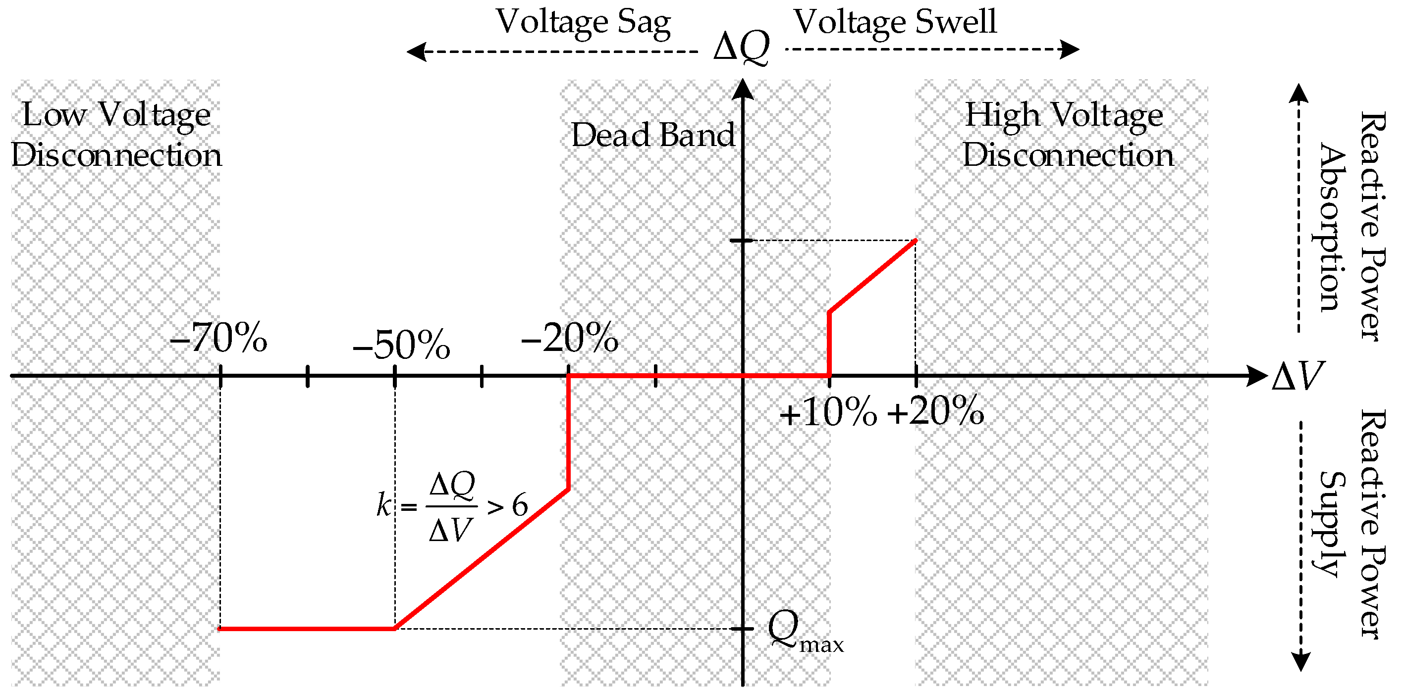
Figure 3.
Distributed control for LVRT operation.
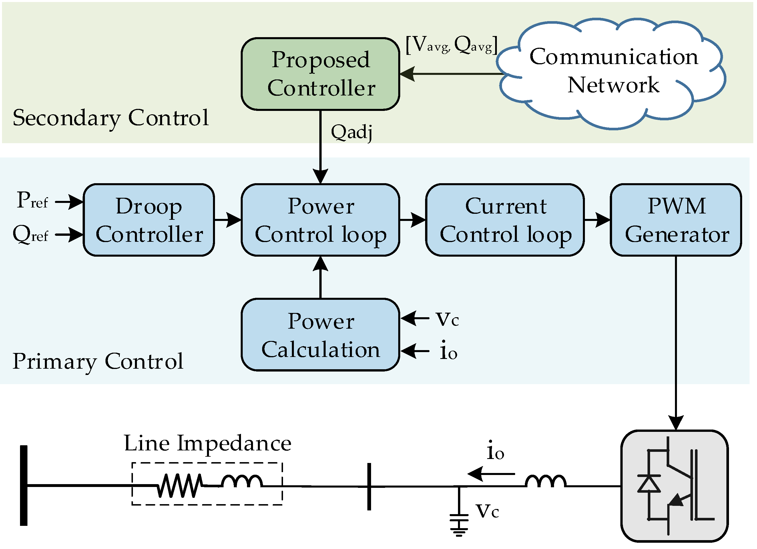
Figure 4.
Control diagram of power and current control loops.

Figure 5.
Control diagram of the secondary control layer.
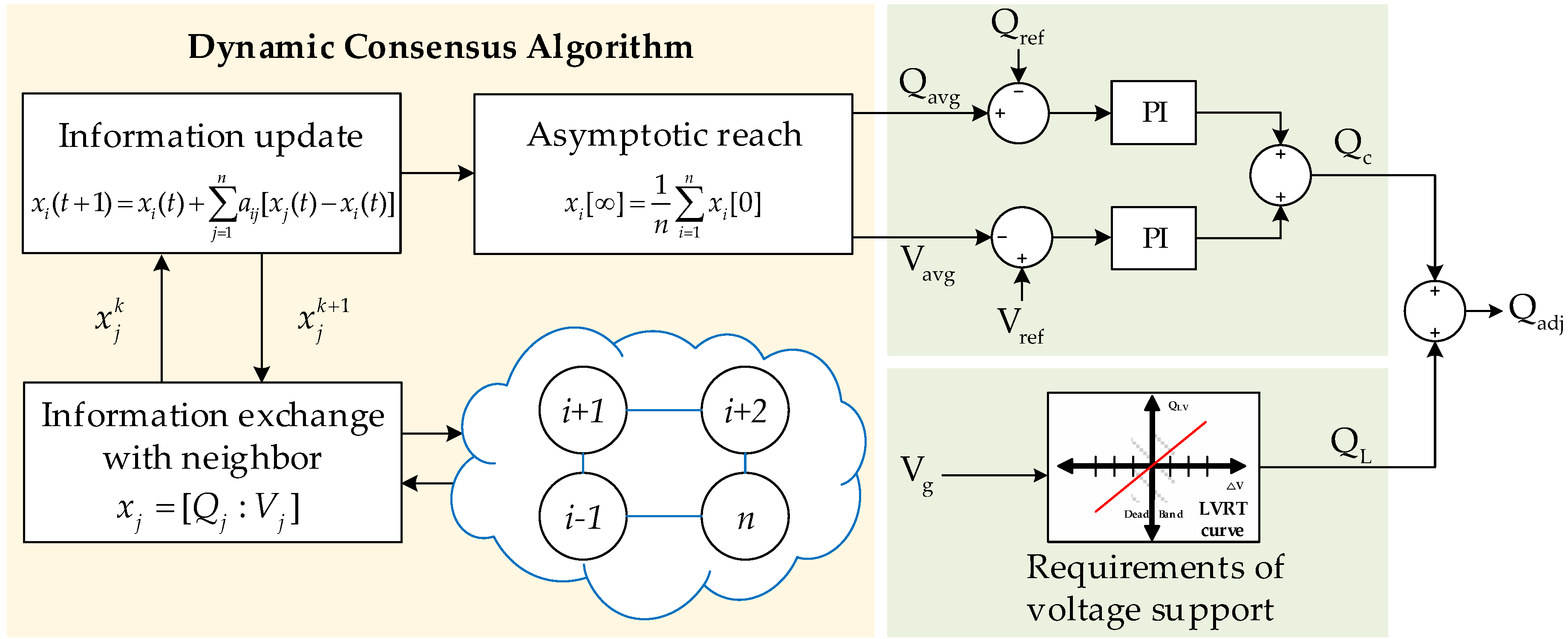
Figure 6.
Configuration of the tested microgrid (MG) system.
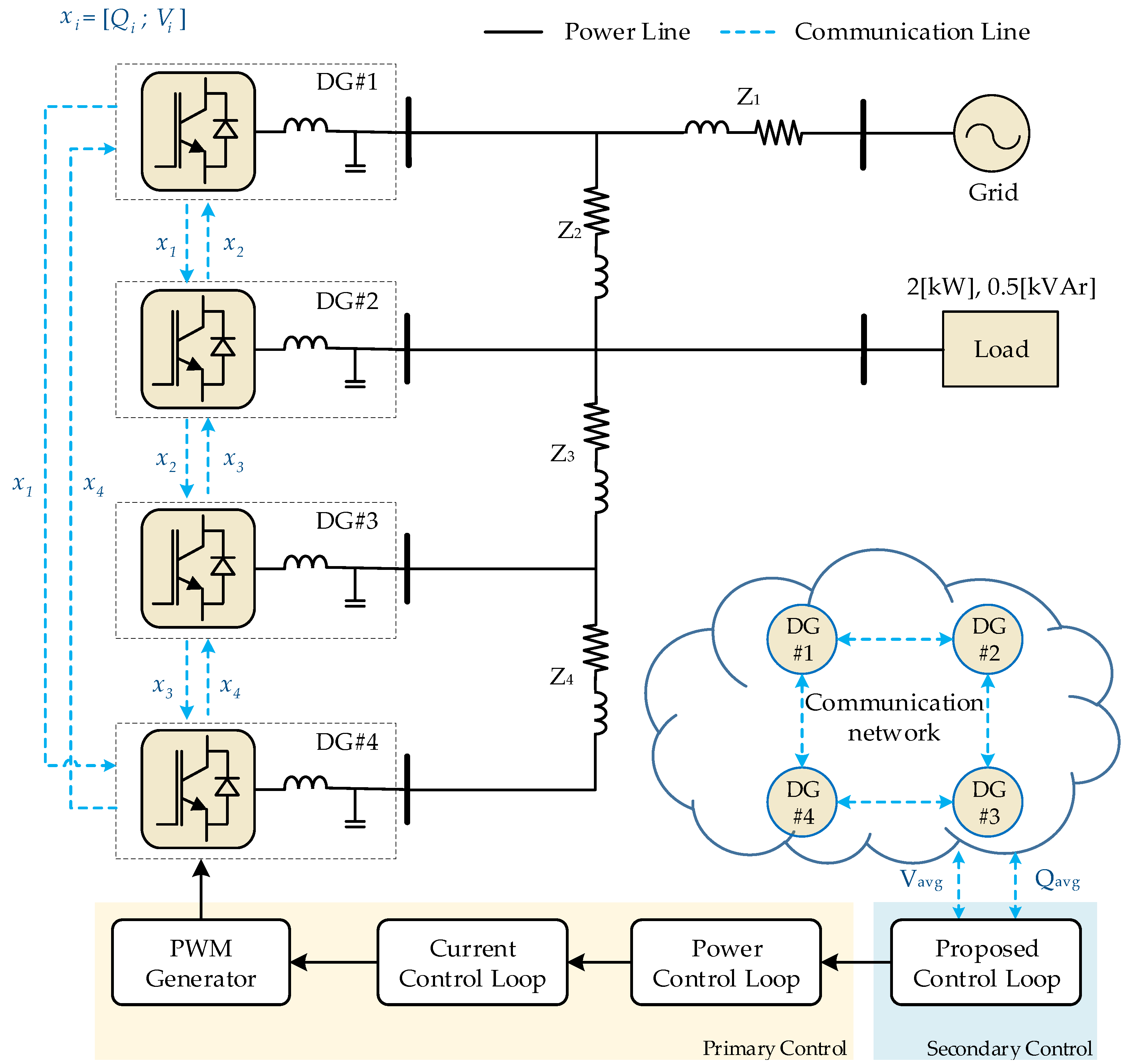
Figure 7.
Output voltage of each distributed generators (DG): (a) without LVRT; (b) centralized method; (c) proposed method.
Figure 7.
Output voltage of each distributed generators (DG): (a) without LVRT; (b) centralized method; (c) proposed method.
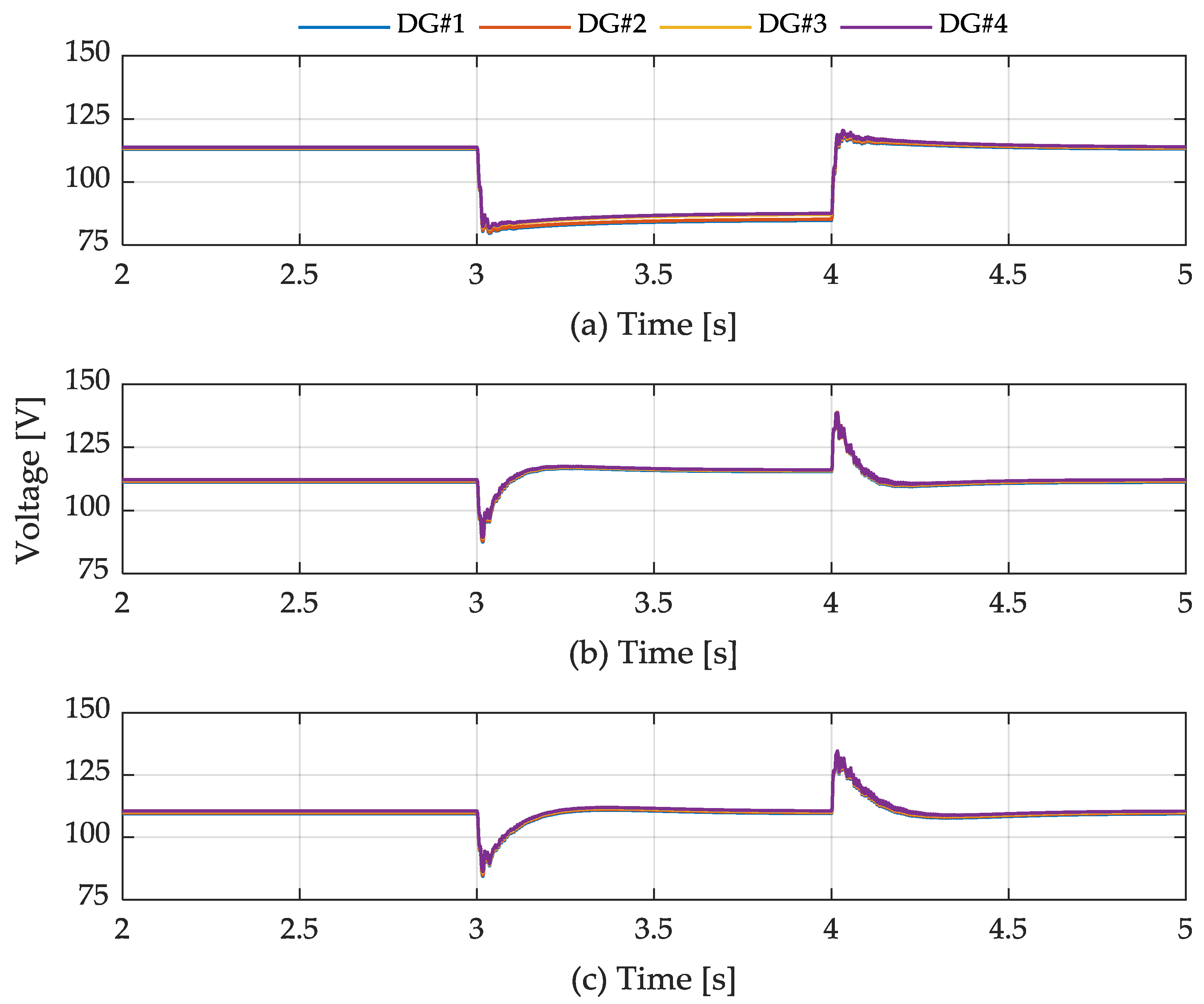
Figure 8.
Output reactive power of each DG: (a) without LVRT; (b) centralized method; (c) proposed method.
Figure 8.
Output reactive power of each DG: (a) without LVRT; (b) centralized method; (c) proposed method.

Figure 9.
Output current of each DG: (a) without LVRT; (b) centralized method; (c) proposed method.

Figure 10.
Output active power of each DG: (a) without LVRT; (b) centralized method; (c) proposed method.
Figure 10.
Output active power of each DG: (a) without LVRT; (b) centralized method; (c) proposed method.

Figure 11.
Output voltage of each DG: (a) centralized method; (b) proposed method.
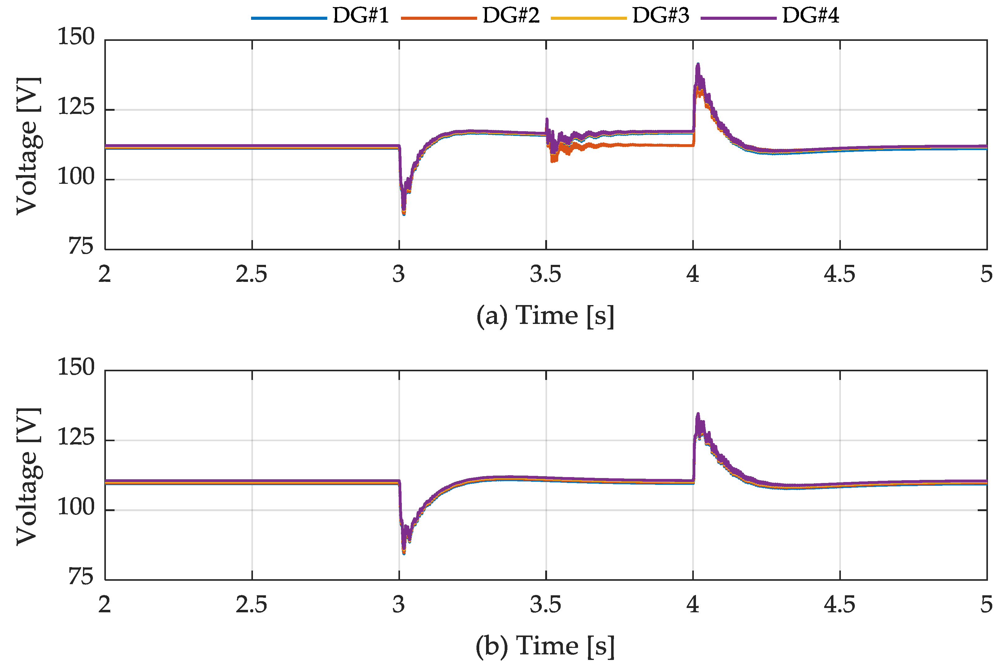
Figure 12.
Output reactive power of each DG: (a) centralized method; (b) proposed method.

Figure 13.
Output current of each DG: (a) centralized method; (b) proposed method.
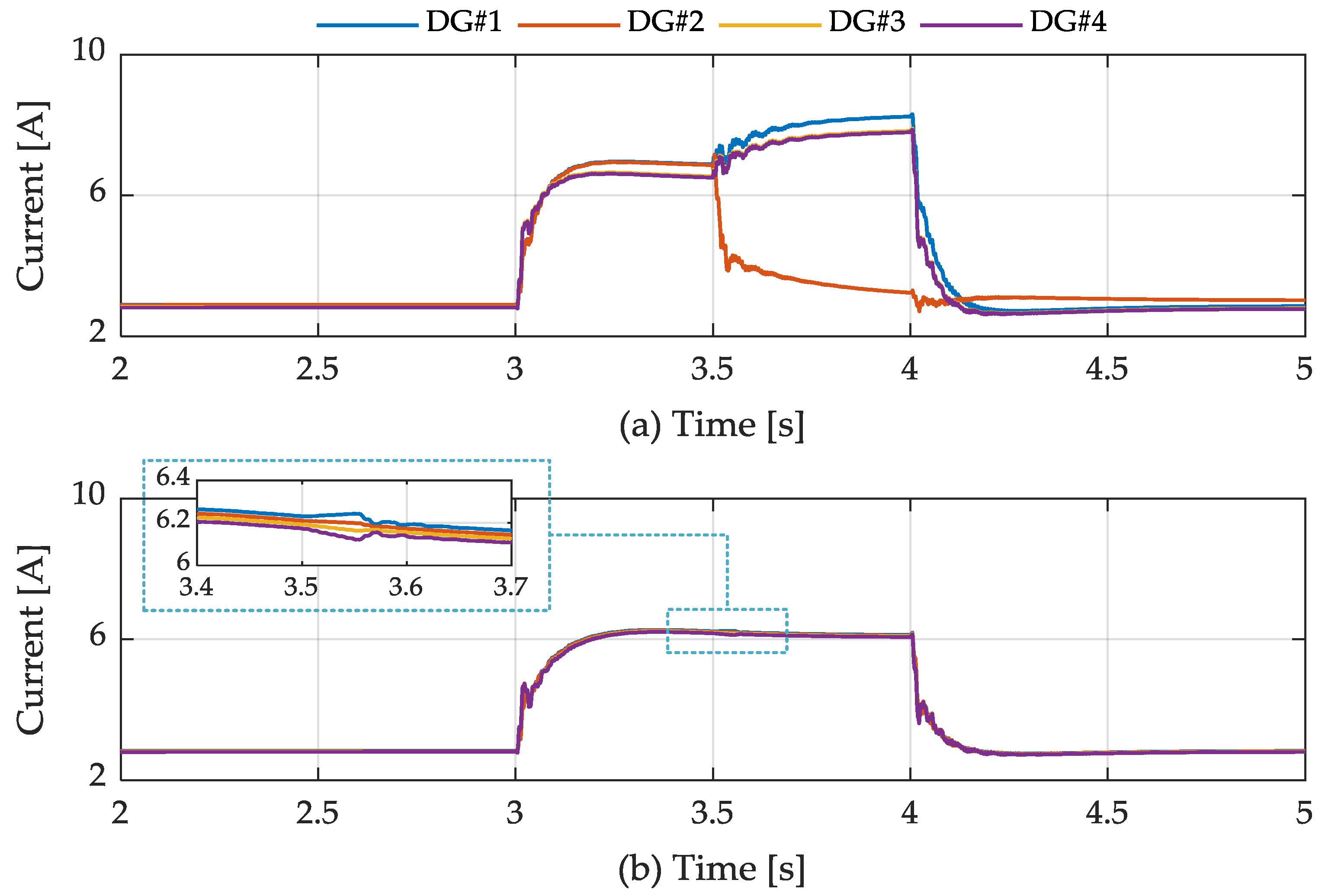
Figure 14.
Output active power of each DG: (a) centralized method; (b) proposed method.
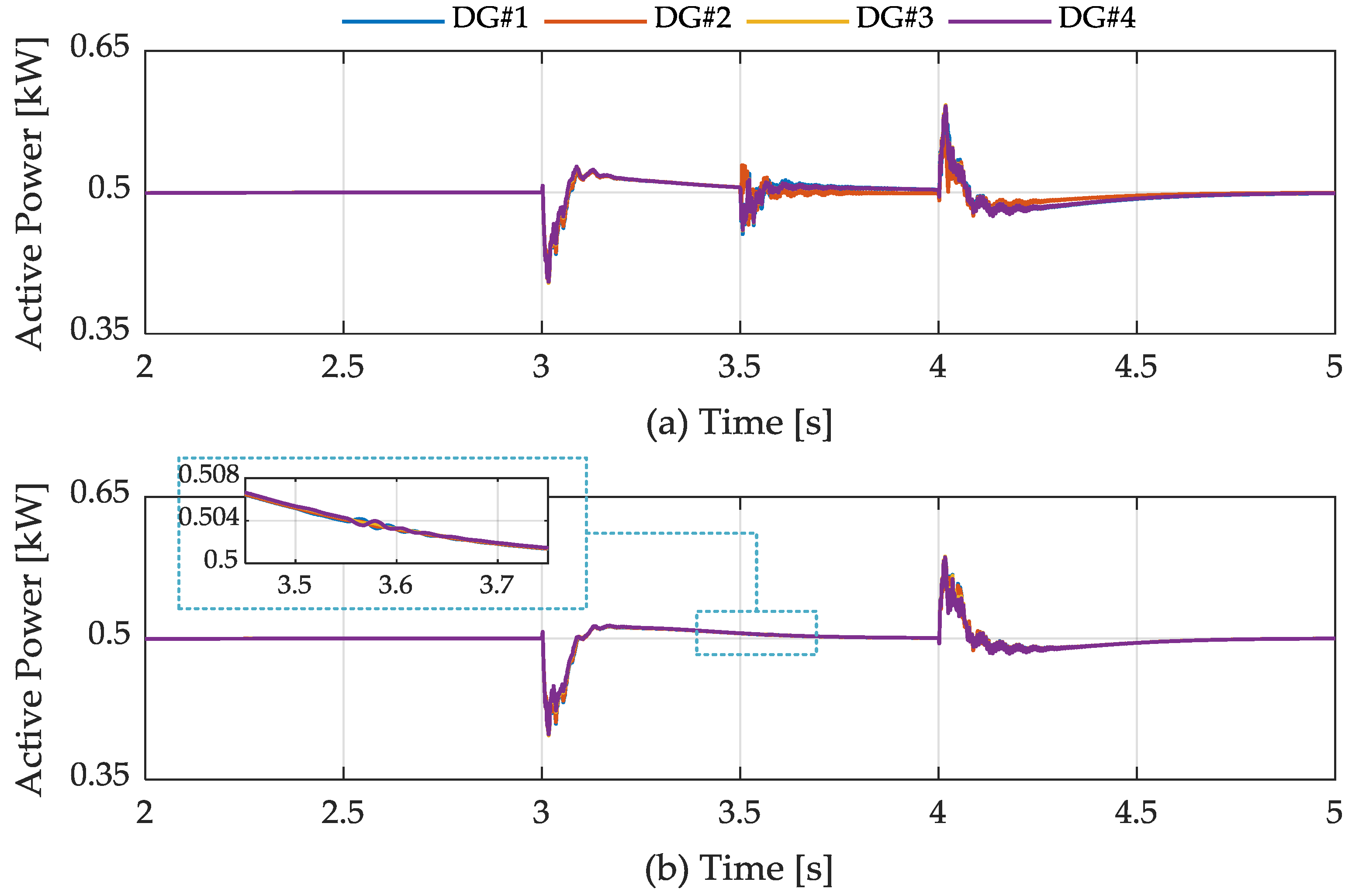
Figure 15.
Output voltage of each DG: (a) centralized method; (b) proposed method.
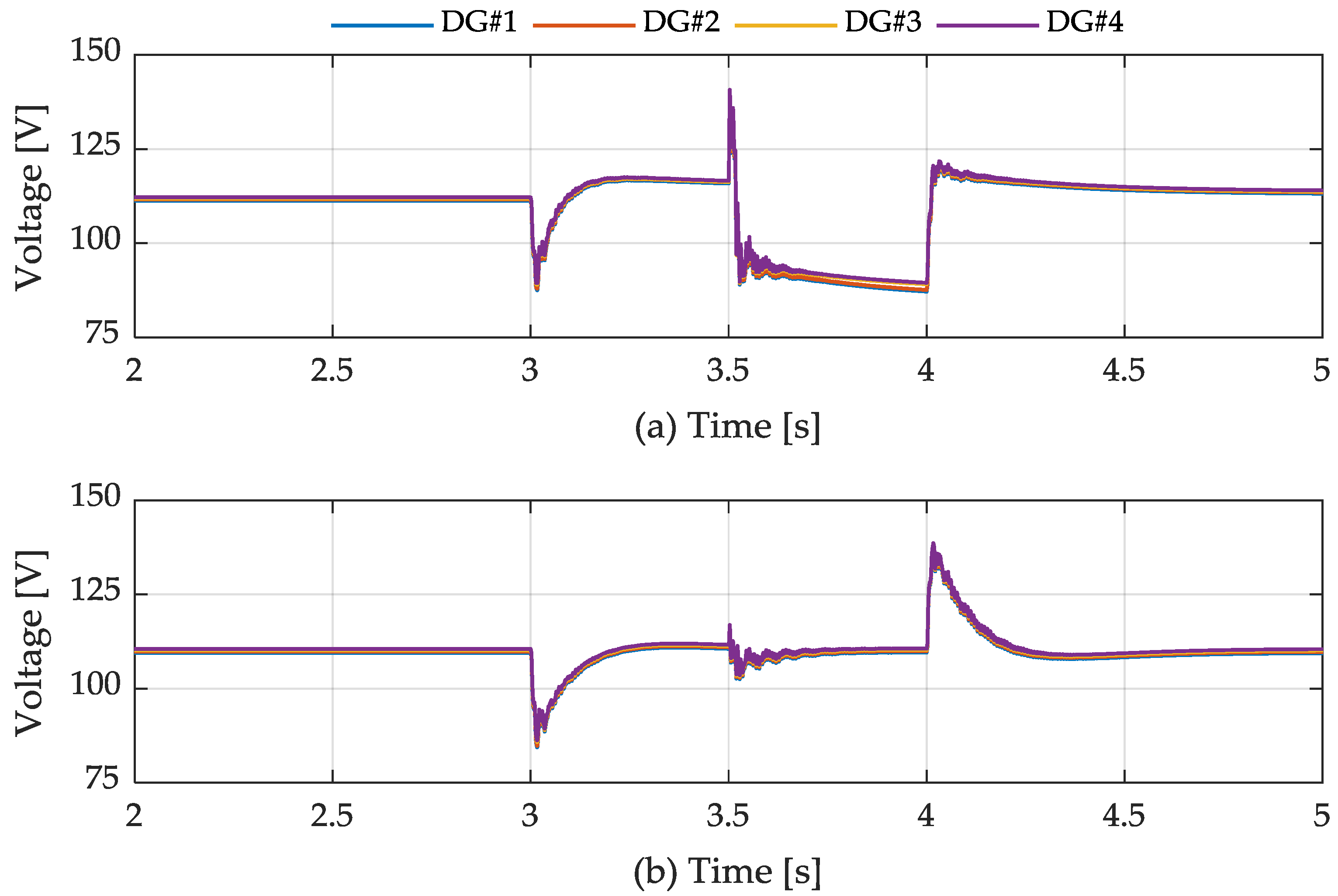
Figure 16.
Output reactive power of each DG: (a) centralized method; (b) proposed method.
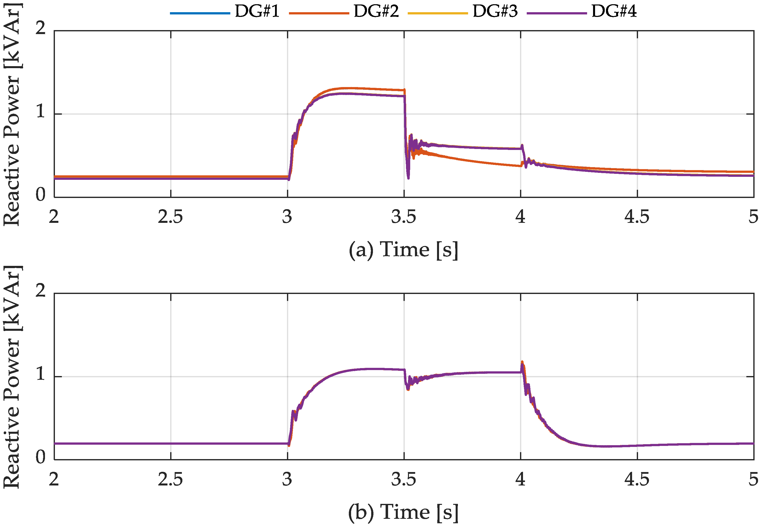
Figure 17.
Output current of each DG: (a) centralized method; (b) proposed method.
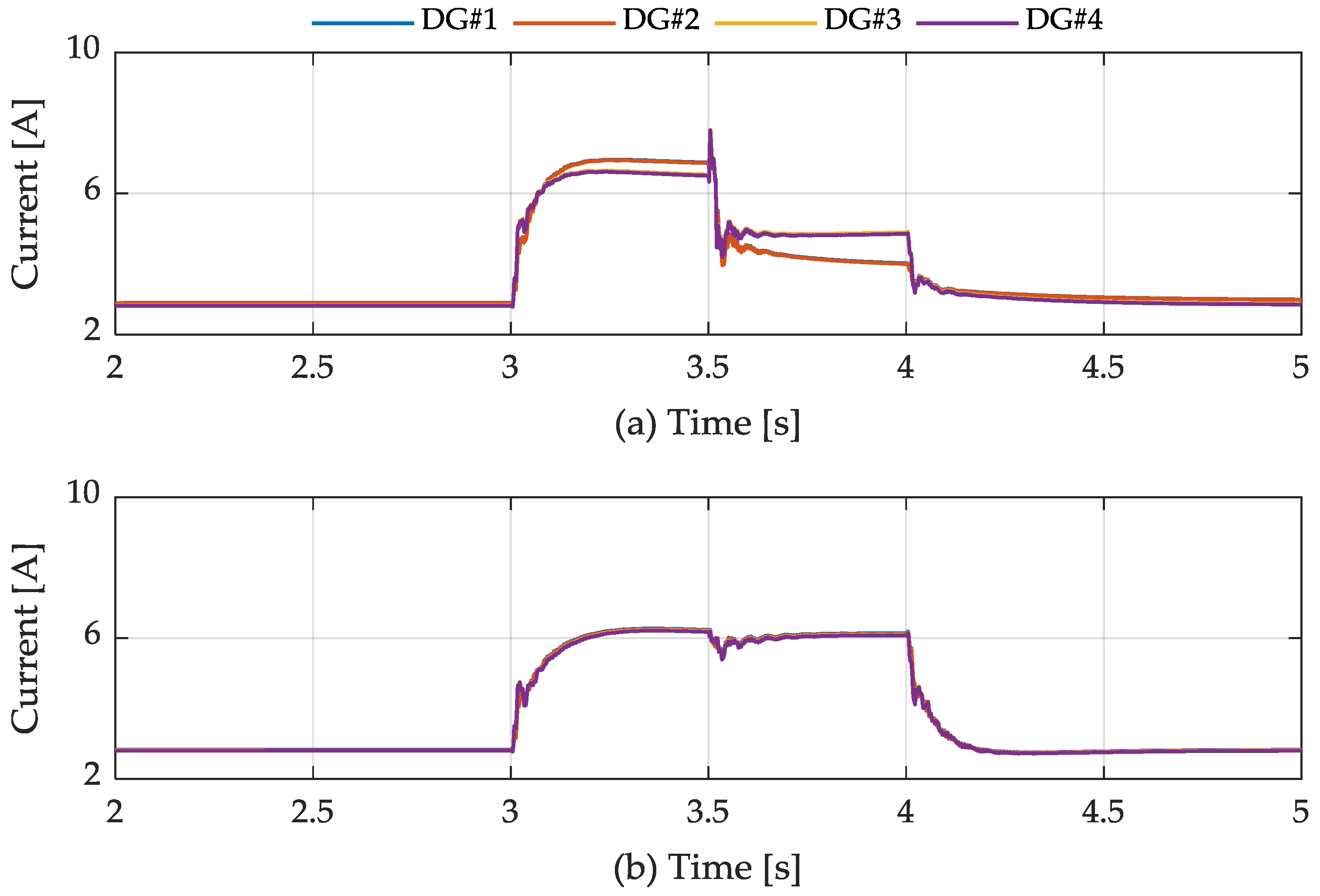
Figure 18.
Output active power of each DG: (a) centralized method; (b) proposed method.

Table 1.
System parameters.
| Symbol | Parameters | Value | Unit |
|---|---|---|---|
| Rated RMS voltage | V | ||
| Rated voltage frequency | Hz | ||
| Switching frequency | kHz | ||
| Filter inductance | mH | ||
| Filter capacitance | |||
| Primary power controller proportional coefficient | - | ||
| Primary power controller integral coefficient | - | ||
| Primary current controller proportional coefficient | - | ||
| Primary current controller integral coefficient | - | ||
| Secondary reactive power controller proportional coefficient | 0.5 | - | |
| Secondary reactive power controller integral coefficient | 300 | - | |
| Secondary voltage controller proportional coefficient | 0.8 | - | |
| Secondary voltage controller integral coefficient | 200 | - | |
| Line impdance#1 | 0.08 + j0.94 | Ω | |
| Line impdance#2 | 0.04 + j0.46 | Ω | |
| Line impdance#3 | 0.06 + j0.62 | Ω | |
| Line impdance#4 | 0.06 + j0.62 | Ω |
© 2018 by the authors. Licensee MDPI, Basel, Switzerland. This article is an open access article distributed under the terms and conditions of the Creative Commons Attribution (CC BY) license (http://creativecommons.org/licenses/by/4.0/).
Share and Cite
MDPI and ACS Style
Lee, W.-G.; Nguyen, T.-T.; Yoo, H.-J.; Kim, H.-M. Low-Voltage Ride-Through Operation of Grid-Connected Microgrid Using Consensus-Based Distributed Control. Energies 2018, 11, 2867. https://doi.org/10.3390/en11112867
AMA Style
Lee W-G, Nguyen T-T, Yoo H-J, Kim H-M. Low-Voltage Ride-Through Operation of Grid-Connected Microgrid Using Consensus-Based Distributed Control. Energies. 2018; 11(11):2867. https://doi.org/10.3390/en11112867
Chicago/Turabian StyleLee, Woon-Gyu, Thai-Thanh Nguyen, Hyeong-Jun Yoo, and Hak-Man Kim. 2018. "Low-Voltage Ride-Through Operation of Grid-Connected Microgrid Using Consensus-Based Distributed Control" Energies 11, no. 11: 2867. https://doi.org/10.3390/en11112867
Note that from the first issue of 2016, this journal uses article numbers instead of page numbers. See further details here.