Study of the Circular Flat Spiral Coil Structure Effect on Wireless Power Transfer System Performance


1
Jiangsu Province Laboratory of Mining Electric and Automation, China University of Mining and Technology, Xuzhou 221008, China
2
Electrical Energy Management Research Group, University of Bristol, Bristol BS8 1TH, UK
*
Author to whom correspondence should be addressed.
Energies 2018, 11(11), 2875; https://doi.org/10.3390/en11112875
Submission received: 19 September 2018
/
Revised: 18 October 2018
/
Accepted: 18 October 2018
/
Published: 23 October 2018
(This article belongs to the Special Issue Wireless Power Transfer 2018)
Abstract
:This paper analyses the relationship between the coil design parameters and the system performance, including power transfer efficiency and amount, when circular flat spiral coils are adopted in a wireless power transfer (WPT) system. Coil design variables including outer radius, inner radius, channel width and coil turns are thoroughly studied to improve the system performance with a limited maximum outer radius for practical purposes. A two-coil WPT system has been built to verify the analysis, and the experimental results show good consistency with the theoretical calculations and simulation results, which show that the coil design parameters have a significant impact on the system performance, even with the same coil size. In the experiments, the coil-to-coil distance is 150 mm, the maximum coil outer radius is limited in 300 mm, and the DC input voltage and the load resistance are 100 V and 5 Ω, respectively. When the coils are tightly-wound in the most traditional way to maximize the coil size, the coil-system efficiency is 62.6% with only 4.5 W load power. In contrast, the efficiency optimized coil can improve the coil-system efficiency to 91.2% with the outer radius stayed the same. Besides, when the power transfer efficiency and amount are considered simultaneously, the system can achieve 1279 W load power with 85.94% coil-system efficiency.
1. Introduction
Generally, WPT systems utilize the magnetic field to transfer energy from a power source to isolated loads across a large air gap without direct electrical contacts which can be used for powering up any electric equipment. A WPT system is at least composed of two coils which are known as transmit and receive coils and thus can be named a two-coil WPT system [1,2,3]. Usually, these two coils are separated with an air gap and tuned to resonate by the compensation circuit at the same natural frequency which is known as resonant wireless power transfer (RWPT). Due to the elimination of physical electric contacts, the WPT system greatly enhances the flexibility and safety of electric equipment and attracts more and more attention recently. However, as the energy is wirelessly transferred through the mutual inductance between the transmit and receive coils, the leakage inductance does not have a direct contribution to the active power transfer, and the large gap between the transmit and receive coils will lead to a very small coupling coefficient between the two coils. This feature leads to a WPT system with a large leakage inductance but a small mutual inductance. Hence, different coil structures have been derived to counteract the effect of low coupling coefficient to improve the performance of the WPT system [4,5,6] as the coupling coefficient is not only dependent on the coil-to-coil relative position, but also depends on the structure of the coils [7]. Besides the self-inductance, mutual inductance and parasitic resistance of the coils are all impacted by the structure of the coils, which are also the crucial impact factors on the power transfer efficiency and amount. Therefore, the study on the design of the coils is crucial in the research about the WPT systems.
Concerning the study on the coil structure, circular flat spiral coils are widely adopted in the WPT studies as this structure has been widely adopted to help improve power transfer performance and gain higher tolerance to misalignment compared to other coil structures [8]. In [9], the author eliminated the frequency splitting phenomenon and improved the efficiency of the system by enlarging the coils. While in practice, for mounting the coils in the restricted space limited by the electrical equipment, the size of the coils should be limited in a certain range and cannot be enlarged optionally. In [10], the author studied the impacts of the circular flat spiral coil structure regarding the mutual inductance based on a compact model. However, the power transfer efficiency and power transfer capacity are not concerned in this study, which practically are crucial and intuitive factors for the designers. Besides, not only the mutual inductance will have impacts on the system performance, but the self-inductance and the parasitic resistance of the coils also have serious influence on the system performance. In [11], the authors discussed the optimization of geometric design based on tightly-wound circular spiral coils by using the reflected impedance method in a SP compensated WPT system. It is found out that the coil outer/inner radius can be optimized to maximize the coupling coefficient according to the power transfer distance, therefore, the power transfer efficiency can be accordingly maximized. The coils studied in this paper are tightly wound, while it is found out in our work that optimizing the channel width of the coil can further improve the power transfer efficiency. Besides, the power transfer amount and the maximum outer radius should also be considered in the design of a WPT system for practical purpose, which is also lacked in this paper. Reference [12] studied the effects of coil turns and outer radius on the coil quality factor and the power transfer efficiency and it is shown that the larger the coil is, the higher system efficiency will be. Additionally, tight-wound coils can also contribute to improving the system efficiency, but for different coil designs, other system parameters didn’t remain constant in the experiments, i.e., coil-to-coil distance, load resistance, and the power transfer capacity was also not considered in the analysis. Most of the studies about the circuit analyses on the WPT system are based on coupled circuit model in terms of the basic physical parameters of the coil-system (self-inductance, mutual inductance and parasitic resistance). Adopting the quality factor (Q-factor) of the coils as the optimization factor to improve the performance of the WPT system is another choice. For a two-port WPT system, the maximum achieved power transfer efficiency can be expressed in terms of the coupling coefficient between the transmit and receive coils and the Q-factor of the coils [13], which is very helpful to improve the power transfer efficiency by optimizing the coil design as only the Q-factor of the coils and the coupling coefficient between the transmit and receive coils need to be considered in the design. It has also been proven that high Q-factor resonators enable efficient energy transfer at lower coupling rates, i.e., at greater distances and/or with more positional freedom than is otherwise possible [14]. However, coupled circuit model in terms of the basic physical parameters of the coil is more clear and accessible for the readers to understand the impact factors caused by the coils on the electrical performance of the WPT system including the power transfer efficiency and amount simultaneous, therefore, it is adopted in this work. Regarding the wires used for winding the coils, in [15], the diameter of the wire as a design variable is studied concerning the current destiny. In [16], the influence of skin effect and proximity effect of Litz wires are studied. Besides, an iterative method to find the optimum inductor trace width for any coil-turns is presented in [17] which can help to optimize the inductor layout to reach the maximum Q-factor at a given frequency. Reference [18] studied the relationship between the winding trace thickness and the Q-factor of the coil, and an air-core spiral inductor with winding trace thicknesses decreasing towards the centre is demonstrated, which achieved Q-factor improvement over a wide frequency range compared to uniform thickness inductors. These papers can help designers to choose suitable wire radius with specific requirements.
In our work, it has been found that too many coil turns will lead to excessive coil parasitic resistance, which will have a dominant impact on the system efficiency rather than the mutual inductance and decrease the overall system efficiency. In terms of the power transfer capacity, there always exists a maximum point corresponding to the relationship between the coil-system physical characteristic (self-inductance, mutual inductance and parasitic resistance) and the load resistance according to the maximum output power theorem. Besides, tightly-wound coils will seriously limit the power transfer amount with other system electrical parameters fixed as the self-inductance will rapidly increase due to too tight coils or too many coil-turns. Therefore, wireless power transfer efficiency and capacity should be concerned at the same time regarding the optimization in the coil design.
To summarize, in the existing literatures, the impacts of coil structure concerning the power transfer efficiency and capacity are not comprehensively investigated. Besides, the size of the coils is not considered as a constraint in most studies, which is a critical problem for practical use. And most of the coils in these literatures are tightly-wound type without considering the parasitic resistance of the coils. Therefore, further investigation on the coil structure optimization is meaningful.
This paper focuses on circular flat spiral coils with a limited outer radius since this structure can help to enhance system performance and the limited outer radius is more meaningful for practical purposes. Even though this paper only focus on the circular flat spiral coils, the analysis concept is also suitable for optimizing any other coil structures such as square flat spiral coils or double D pads. Besides, it is assumed that the transmit coil has the same size and structure with the receive coil, because a symmetry design can not only simplify the analysis and experiment but also can be used for the research in bi-directional WPT systems. The performance of the WPT system is studied based on a two-coil stationary system, which is more stable and has a better coupling coefficient of the coils [19]. The primary objective of the coil optimization is the coil-system efficiency but the power transferred capacity is also considered in this paper.
2. Theoretical Analysis
2.1. Two-Coil WPT System Circuit Model
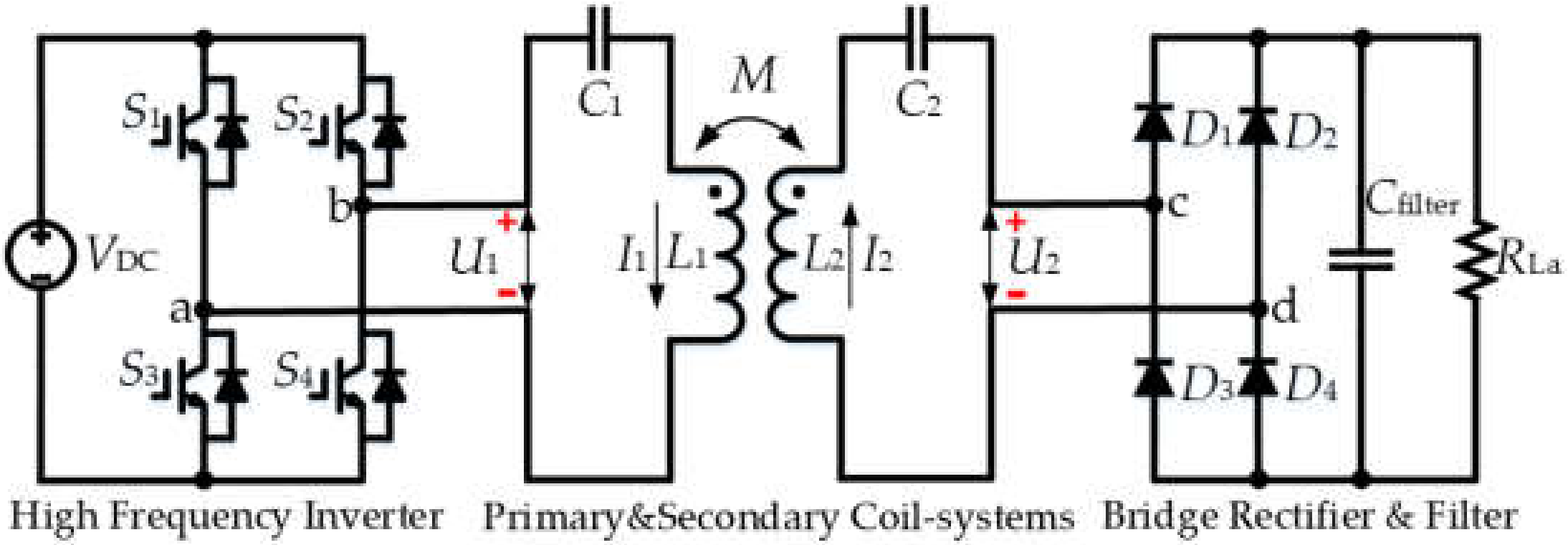
The laboratory two-coil WPT system circuit schematic diagram is shown in Figure 1 which adopts the series-series (SS) compensation topology and the whole system can be separated into the primary side and the secondary side. The primary side coil-system consists of the transmit coil L1 and its series connected compensation capacitor C1. It is driven by a voltage source high frequency inverter that applies a square-wave voltage to the L1C1 resonant circuit. The primary side coil-system is made resonant to reduce the Voltage-Ampere (VA) required to set up the required primary current. The circuit is purely resistive at the fundamental resonant frequency, but has a high inductive reactance to harmonics; as a result, the current flowing through the L1C1 resonant circuit is a sinusoidal current at the fundamental frequency. This current generates a magnetic field around the transmit coil, which induces a voltage in the receive coil by mutual inductance; the induced voltage can be rectified to provide DC power to a load. The compensation capacitor on the secondary side coil-system C2 cancels out the inductive reactance of the receive coil, which would otherwise seriously limit the load current. In this way transfer of electric energy through the air from the transmit coil to the receive coil is achieved [20,21].
In order to build up the mathematic model of the WPT system, the circuit schematic diagram shown in Figure 1 can be simplified to the equivalent simplified model as shown in Figure 2, where U1 is the output voltage phasor of the high frequency inverter applied to the primary coil-system; U2 is the output voltage phasor of the secondary coil-system and the input voltage to the H-bridge rectifier. The H-bridge rectifier, filter capacitor and the actual load are treated as an equivalent resistance RL. In this simplified model, R1 and R2 are the parasitic resistance in the primary and secondary sides respectively, consisting of the resistance of the coils and the compensation capacitors. I1 and I2 are the current phasors for the primary side and the secondary side, respectively.
To the system load including the rectifier and filtering capacitor, the secondary-side series resonant circuit forces a sinusoidal current through the rectifier, which results in a square-wave voltage at the rectifier input. A capacitor Cfilter at the rectifier output bypasses ripple current at switching frequency from the load, therefore, the voltage across the output capacitance Cfilter and the load is nearly constant, with a small ripple and the root-mean-square (RMS) value of the fundamental component of the square voltage waveform is of its peak value. Because power transfer is the product of the RMS value of the sinusoidal current and the RMS value of the fundamental of the square voltage waveform, assuming 100% power efficiency, according to the law of energy conservation, then the relationship between the actual and the equivalent loads can be expressed as Equation (1):
For a resonant WPT system, the compensation capacitance is chosen to resonate with the self-inductance of the coil at a specific resonant angular frequency (ωr) as Equations (2) and (3):
With the lumped-element circuit shown in Figure 2, the WPT system can be expressed in the matrix form according to Kirchhoff voltage law (KVL) as follows:
where ) is the impedance of the primary side; is the impedance of the secondary side; and is the driving angular frequency.
Therefore, the current phasor in the primary and secondary sides can be derived from Equation (4):
When the WPT system operates under resonant conditions, that is, when the driving frequency equals the resonant frequency (), the impendence of the primary and secondary sides Z1 and Z2 are both pure resistant, which means that the currents flowing in the primary side I1 is in phase with the output voltage of the DC-AC inverter U1, and the currents flowing in the secondary side I2 is in phase with the input voltage of the AC-DC rectifier U2. Besides, it has been analysed that the coil currents in the primary-side and the secondary-side are both sinusoidal, therefore, according to the fundamental harmonics approximation (FHA), the power transferred from the primary side (inverter output power), the power received by the secondary side (rectifier input power) and the coil-system efficiency (rectifier input power divided by inverter output power) can be expressed as Equations (7)–(9), respectively, under resonant conditions:
Considering the coil-system efficiency, it is clear that the larger the mutual inductance M is, the higher the coil-system efficiency will be; and the larger the coils’ parasitic resistance is, the lower the coil-system efficiency will be. Obviously, the wireless power transfer efficiency can be effectively improved by increasing the mutual inductance with the same coils, decreasing coil parasitic resistance or increasing the self-inductance while keep the same coupling coefficient, which can be achieved by optimizing the design of the transmitter and receiver coils as those coil-system physical parameters are closely related to the structure of the coils. Meanwhile, the impacts caused by the changes in the coil-system parameters on the power transferred to the secondary side can also not be neglected for practical purpose. From Equations (7) and (8) it can be found out that the transmitted power in the primary side and the received power in the secondary are both decided by the coil-system physical parameters (self-inductance, mutual inductance, parasitic resistance) particularly by the mutual inductance when the coil parasitic resistance is relatively small compared to the load resistance, and the larger the mutual inductance is, the smaller the produced power will be. Concerning the received power in the secondary side, there will always a maximum point regarding to the mutual inductance according the impendence matching theory.
2.2. Circular Flat Spiral Coil Model
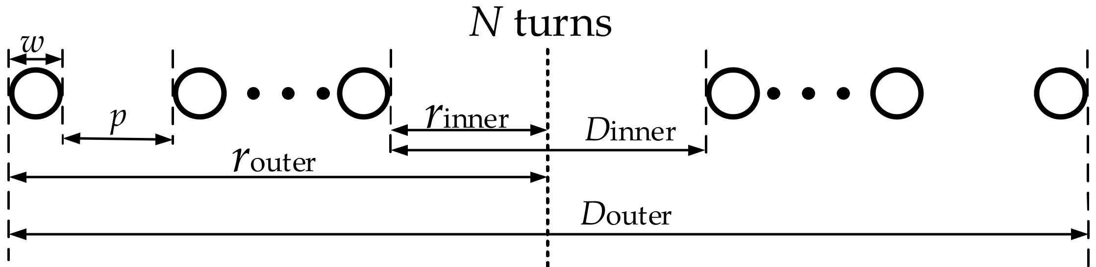
When the WPT technology is used for practical electric equipment, the size of the coils is limited usually within a certain space. Therefore, in order to optimize the design of the coil to improve the WPT system performance, it is necessary to figure out the impacts on the coil-system physical parameters caused by the coil design parameters. The section views of a circular flat spiral coil used as the transmit/receive coils is shown in Figure 3, where N is the number of turns of the circular flat spiral coil, rinner and router are the inner radius and the outer radius of the coil respectively, w is the diameter of the wires used for winding the coils, and p is the channel width between two adjacent wires.
The self-inductance of the circular flat spiral coil can be derived from a modified Wheeler’s formula [22,23] for a single-layer helical coil, while accounting for the conversion from inches to meters (39.37 inch/m) and µH to H (10−6) as in Equation (10). This expression has been valid accurate in [24,25] with a wide variety of coils for most geometries except when the coil has very few turns or when the channel width is very large compared to the wire diameter (p >> w) [26]. From Equation (10), it can be found that the coil self-inductance is correlated with the coil turns, wire width, channel width and the outer radius of the coil:
Power loss in a circular flat spiral coil consists of radiation and conduction losses. Typically, the size of WPT coils are relatively small compared to the operating wavelength, thus, conduction loss is the dominate loss mechanism, and the radiation loss is normally negligible. Conduction loss is dependent on the skin effect (12) and proximity effect (13). Both effects confine current flow to smaller cross-section areas through the conductor, which increases the effective resistance of the conductor [27].
For tightly-wound spiral coils, the parameter that contributes most to RAC is the channel width because of the proximity effect. Additionally, RAC is nonlinear and inversely proportional to the channel width p. Therefore, the tighter of the coil is, the larger of RAC will be. However, it can be found out from Equations (5) and (6) that, the currents flowing in the primary and secondary sides are both affected by the parasitic resistance of transmit and receive coils, and according Equations (11)–(16), the current in turn affect the parasitic resistance of transmit and receive coils. Therefore, it is difficult to accurately calculate the parasitic resistance of the tightly-wound spiral coils in a WPT system [16].
where is the length of the wire used for the circular flat spiral coil, is the permeability of free space, and is the conductivity of the conductor, r0 and w is the radius and diameter of the wire respectively, I0 is the current flowing in the wires, and H stands for the H-field and the detailed calculation process can be found in [28].
For loosely-wound coils, proximity effect is negligible [26], so RAC is mostly influenced by skin effect. RAC can be approximately derived from the high frequency model of AC resistance by Kaiser [26] as a simpler expression shown below:
It can be found from Equations (11)–(17) that no matter whether the circular flat spiral coil is tightly or loosely wound, the structure of the coil will always affect its parasitic resistance.
Since the energy is transferred through the mutual inductance between transmit and receive coils, the calculation of the mutual inductance is crucial. The vertical view of the circular flat spiral coil and the relative location of two coils are shown in Figure 4.
The full expression of the mutual inductance between the two parallel single-turn coils with a loop radius of a and b is shown in Equation (18) [29,30,31], where d and m are the coil-to-coil vertical distance and lateral misalignment, and are the Bessel functions of zero and first order respectively, and x is the integral variable and it ranges from zero to infinity:
This expression does not contain the radius of the coil’s wire w/2. The ratios of the wire radius to the outer radius of the coils are assumed to be sufficiently small.
As stated in previous, the performance of the WPT system will be studied based on a two-coil stationary system, therefore, perfect alignment between the two coils (m = 0) can be easily realized by technologies of mechanical automation, and then the mutual inductance between the two perfectly aligned coils can be simplified as Equations (19)–(24) [25]:
where KS and ES are the complete elliptic integrals of the first and second kind, respectively; ai and bj are the i-th and j-th radius of the transmit and the receive coils respectively; is the mutual inductance between the i-th circular wire in primary coil and j-th circular wire in secondary coil.
From the mutual inductance calculation Equations (19)–(24), it can be found that the design parameters of the circular flat spiral coil will also have impacts on the mutual inductance.
To summarize, the design parameters of the circular flat spiral coil have a significant impact on its physical parameters including the self-inductance, the parasitic resistance and the mutual inductance. With the coil-system physical model, the self-inductance and the mutual inductance can be respectively calculated by Equations (10) and (18), but in order to calculate the AC resistance of the tightly-wound coils, the current flowing in the coils should be obtained according Equation (16), while the self-inductance, mutual inductance and AC resistance will all affect the current, therefore, it is difficult to predict the AC resistance accurately with calculation method. For more precise calculation and prediction, finite element analysis software (Q3D) will also be adopted for simulating the coil system parameters to provide more theoretical foundations before the experiment is carried out and make sure the experimental safety.
3. Impacts of Coil Structure on the WPT System Performance
For practical purpose, the size of the receive coils is usually restricted to the size of the electric equipment, to simplify the analysis and adopt the WPT system in a bi-directional power transfer system, the size of the receive coil is the same as that of the transmit coil. From Section 2.2, it is clear that all the coil design parameters will influence the coil-system physical parameters. In this work, for guaranteeing current density for high power wireless power transfer, 6 mm (diameter) Litz wires are used for fabricating the circular flat spiral coils instead of a 6 mm single strand cooper wire, as all the coils are wound by the same Litz wires, the changing trends of the AC resistance of the coils with the changing of the coil designs will not be affected too much compared to the coils wound by single strand cooper wires, so it will not affect the accuracy of the analysis in this work. Besides, the Litz wire is manufactured in-house and composed of 60 × 0.55 mm-diameter enamelled copper wire conductors to provide an external diameter around 6 mm. As the Litz wire doesn’t contain too many strands, it will not decrease the AC resistance of the coil too much compared to a single cooper wire due to the proximity effect, but can help to wind the coils more easily and save the total cost. And it has been analysed in previous that the AC resistance of the coil will be affected by the coil-design parameters, but it is too complicated to be accurately calculated, therefore, finite element analysis software (Q3D) will be also adopted to simulate the AC resistance of the coils to provide more theoretical foundations before the experiment is carried out and ensure the safe operation of the experiments. The minimum inner radius of the coil is set to be 30 mm for fabricating circular flat spiral coils with 6 mm wires in practical. The maximum size of the coil in this work is restricted in 300 mm which means the maximum outer radius of the coil is 300 mm and this value is 1/3 of a modern cars’ width. The minimum channel width of adjacent wires is zero when the coil is tight-wound. The coil-to-coil vertical distance is set to be 150 mm which is a typical vehicle chassis height.
For the WPT system electrical settings, the system resonant frequency is select to be 85 kHz which is required by SAE J2954 [32] for wireless charging EV batteries. The load resistance is set to be a small value as 5 Ω to reveal the effects caused by the coil parasitic resistance. It should be noticed that the power transfer efficiency can be further improved by adjusting the load resistance according to specific coil-system physical parameters. And the DC voltage is set to be 100 V for decreasing the resonance voltage on the compensation capacitor to decrease the size of the capacitor tank because the film capacitors’ AC rating voltage will decline rapidly with the frequency increasing to tens of kilohertz [33]. Even though the output power may not reach the requirement for charging EVs in all cases, the DC input voltage can be increased to improve the output power easily without affecting the coil-system efficiency according to Equations (8) and (9).
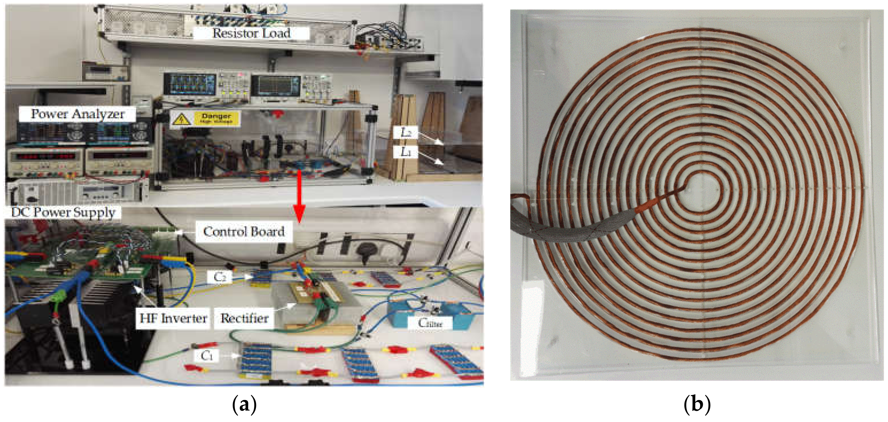
The experimental setup shown in Figure 5 is built up to verify the analysis in this work. EA-PS 81000-30 DC Power supply is used to supply power to the whole system. The primary-side coil system obtains the desired high frequency excitation power from the H-Bridge inverter which is composed by four SiC power MOSFETs S1-S4 (CREE. C2M0040120D), and then the power will be transmitted to the secondary side of the WPT system. At last, the power will be delivered to the load resistors after rectified by an H-bridge rectifier which is also made by four SiC diodes to reduce losses (C4D20120) and a filter capacitor. Two NOORMA 4000 Power analysers are used to measure the DC power supply, inverter output power, rectifier input power and the load power. 100 MHz oscilloscope is used to collect the voltages and currents. The coil self-inductance and parasitic resistance is measured by impedance analyzer (WAYNE KERRR, 6500B).
In the experiments, the input power, output power and coil-system efficiency will be theoretical calculated based on the simulation results of coil-system physical parameters and the mathematical model of the WPT system, and then the experiments can be conducted, which can help to guarantee the safety of the experiments. That is because in this work, the DC input voltage is set to be 100 V, and the rated current of the SiC MOSFET (C2M0040120D) is 60 A at 25 °C (40 A at 100 °C), the half value of the rated current (30 A) is taken as the maximum input current of the DC-AC inverter in the experiments for safety, therefore, the input power of the system should be below 3 kW.
From matrix (4), the mutual inductance can be calculated by Equation (25) when the load resistance, parasitic resistance, driving frequency, coil inductance, primary voltage and current are known in the experiments. When measuring the mutual inductance, the current sense resistors (MP9100-10.0-1%, 10 Ω, 100 W) are adopted instead of the rectifier and power resistors to provide a more accurate secondary side impedance as the impacts caused by the rectifier can be avoided:
3.1. Tightly-Wound: Effects of Outer Radius and Coil Turns
With limited maximum outer radius, a circular flat spiral coil can achieve maximum coil-turns and effective area when it is tightly wound, therefore, tightly wound coils will be firstly studied in this part which means the channel width of adjacent wires, p, equals to zero; and the minimum inner radius of the coil is set to be 30 mm to wind the coil in practical, which leads to the outer radius increase from 30 mm to 300 mm with the turn increase from 1 turn to 45 turns. In the simulation, the channel width is set to be 0.01 mm in order to make the simulation run properly which will cause very small errors. Figure 6a,b describe the scaled schematic diagrams for 5 turns coil and 15 turns coil respectively in this case, it is obviously that the more turn of the coil is, the larger of the coil size will be.
The impacts on the coil-system physical characteristic including self-inductance, mutual inductance and parasitic resistance and the WPT system performance in terms of coil-system efficiency and output power (rectifier input power) are studied regarding to the coil turns in this case. To simplify the experiments and guarantee the safety of the experiments, the practical coil turns are set from 20 turns to 45 turns with 5 turn steps. With the coil-system physical model, the impedance analyser and the assistance of finite element analysis software (Q3D), the relationship between the coil-turns and the coil physical characteristic in this case can be calculated, simulated and measured. As stated in Section 2.2, the AC resistance is difficult to be calculated when the coil is tightly wound, therefore, in this subsection, only the self-inductance and the mutual inductance are analysed by three different methods, the AC resistance is only simulated and measured.
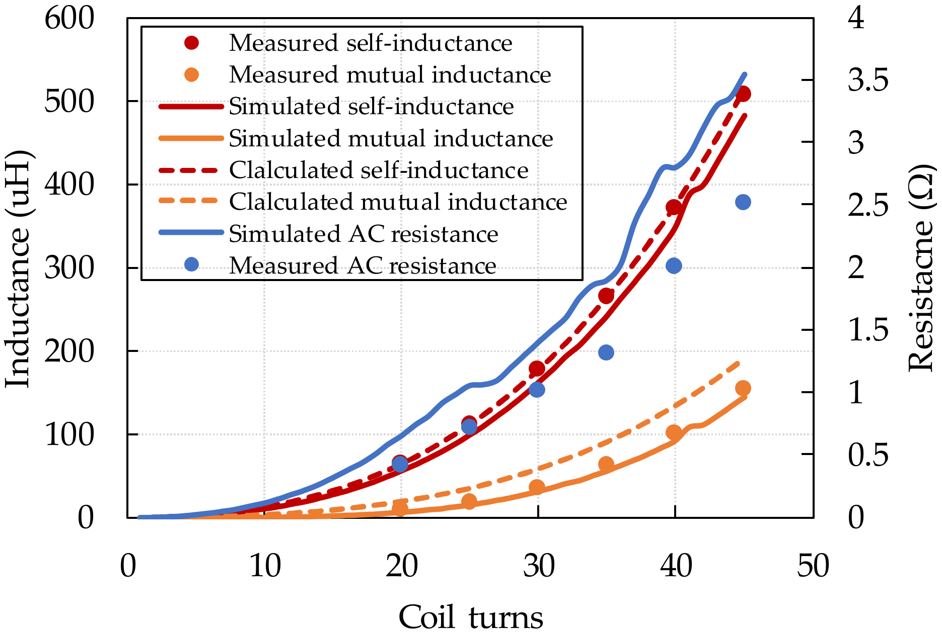
As shown in Figure 7 and in the later analyses about the relationship between the coil-system physical characteristic and the coil design, the dotted lines stand for the calculated results, the solid curves stand for the simulation results, and the scatters are the measured values. It can be found out from Figure 7 that, for the self-inductance, the calculated results, the simulation results and the experimental measured values match very well with slight errors; for the mutual inductance, simulation method can give a more accurate prediction compared to the calculation method; regards to the AC resistance, because in the simulation, the coil is modelled by single strand solid copper, while in practical, the coils is fabricated by Litz wire, so the practical AC resistance is slightly smaller than the simulated results. But all of the calculation, simulation and measured results have the same changing trends with the coil turns. Additionally, it can be found out in this study that with fixed inner radius, the self-inductance, the mutual inductance and the AC resistance of the coils all increase with the coils turns increasing (outer radius increasing). It has been analysed in Section 2 that the larger the mutual inductance and the smaller the parasitic of the coil are, the higher the coil-system efficiency will be. Therefore, the relationship between the coil turns and the coil-system efficiency will be determined by the relative increasing rate of the mutual inductance over the AC resistance. As the simulated coil-system physical is closer to the measured values, the simulated results will be used in the calculation of the WPT system performance to get more accurate predictions.
Figure 8 describes the relationship between the coil turns/outer radius and the WPT system performance. From the calculation results, it can be seen that the output power will increase firstly and then decrease with the coil turns increasing, and then the system output power will be seriously limited when the coil-turns is too much because of the overlarge self-inductance (Figure 7). It has been analysed that the maximum input power of the WPT system is 3 kW. In this case, when the coil-turns is 19, the theoretical output power is 2311 W with 65% efficiency, which means that the input power will be high to 3555 W, and that may lead to device failure. Meanwhile, it can be found out from the theoretical results that the less of the coil-turns is, the higher of the input power will be. For example, when the coil-turns is 15, the theoretical input power is 13,336 W, when the coil-turns is 5, the theoretical input power is 19,200 W. Therefore, the minimal coil-turns is set to be 20 in this case, and the theoretical input power is 2582 W, which is in the safety range. Even though it is difficult to do all the possible coil turns experiments in this case, the changing trends of the experimental output power and the experimental coil-system efficiency with the coil turns both show consistence with the calculation results. Regards to the coil-system efficiency, with the increase in the coil turns, the coil-system efficiency will increases firstly benefit by the increased mutual inductance, and then decreases because the AC resistance of the coil will dominant the coil-system efficiency.
In the calculation, the maximum coil-system efficiency can be achieved is 75.2% at 27 turns with 192 mm outer radius, and the output power is 245 W; while the fully tight-wound coil system (45 turns) can only achieve 53% coil-system efficiency with 5.5 W output power. In the experiments, when the coil-turns is 30, the coil-system efficiency reach to the maximum value at 70.07% with 80 W output power (85 W output power and 72% coil-system efficiency in the calculation), and when the coil-turns is 45, the coil-system efficiency decreases to 62.6% with 4.5 W output power. The errors are caused by the parasitic parameters in the practical system including the stray resistance of the compensation capacitors, the leads and connection nodes in the system, particularly caused by the errors of the coils’ AC resistance under certain operating conditions because the current flowing in the coils will affect its proximity effect, but the influence on the veracity of trend analysis can be neglected.
Obviously, with fixed inner radius, increase the tightly-wound coil turns can effectively improve the coil-system efficiency; within limits, more coil turns can achieve higher coil-system efficiency, but the output power will be limited and too many coil turns will lead to too large parasitic resistance in the coils which will have negative effects on the coil-system efficiency.
3.2. Tightly-Wound: Effects of Inner Radius and Coil Turns
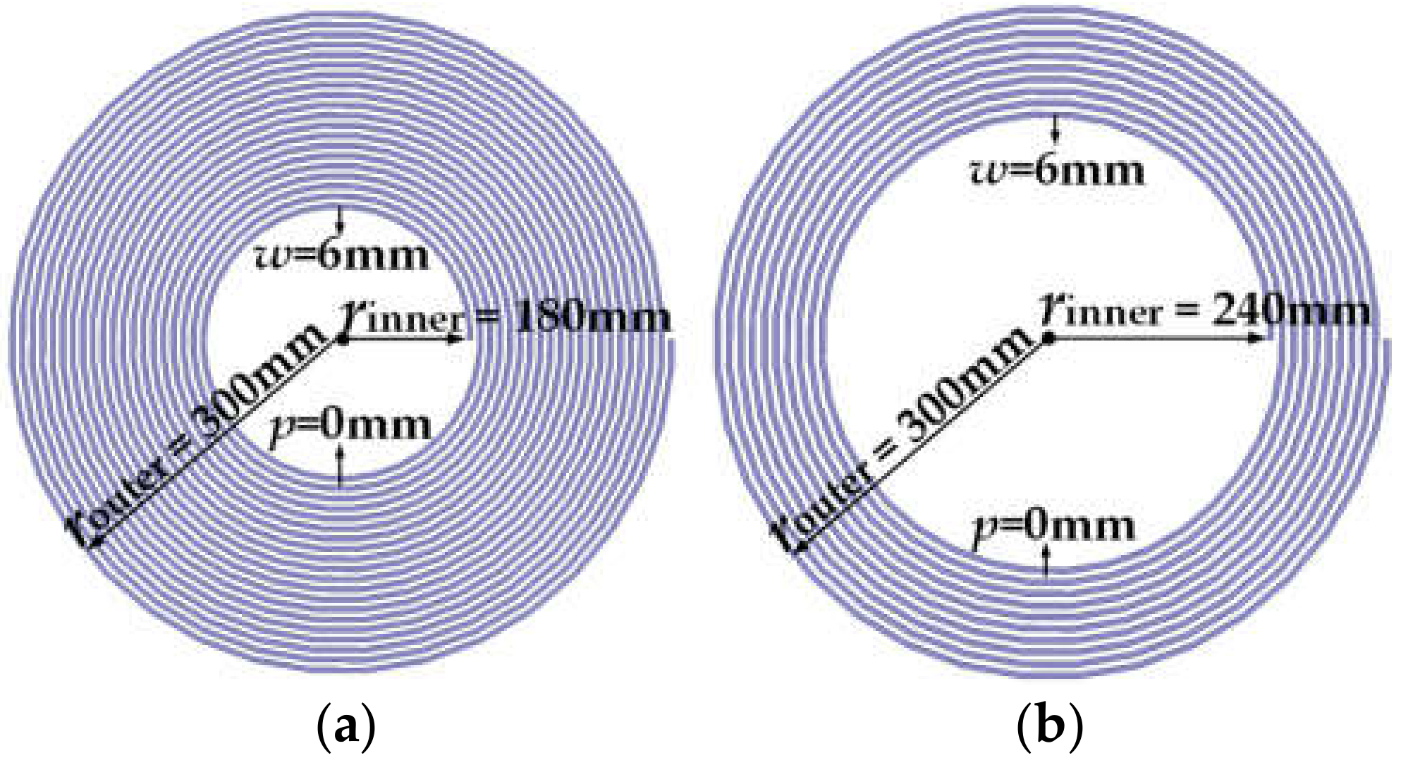
To study the impact caused by the inner radius of the coil with fixed outer radius (300 mm), in this case, the coils are still tightly wound, with the inner radius increase from 30 mm to 300 mm, the coil-turns will decrease from 45 to 1 and the coil-turns will also be used for response various inner radius. For experiment convenience, the turns of the coil are set from 5 turns to 45 turns with 5 turns step. Figure 9a,b describe a 20 turns coil and a 10 turns coil, respectively, in this case. It can be seen that the more the coil-turns are, the more intensive and effective area of the coil will be.
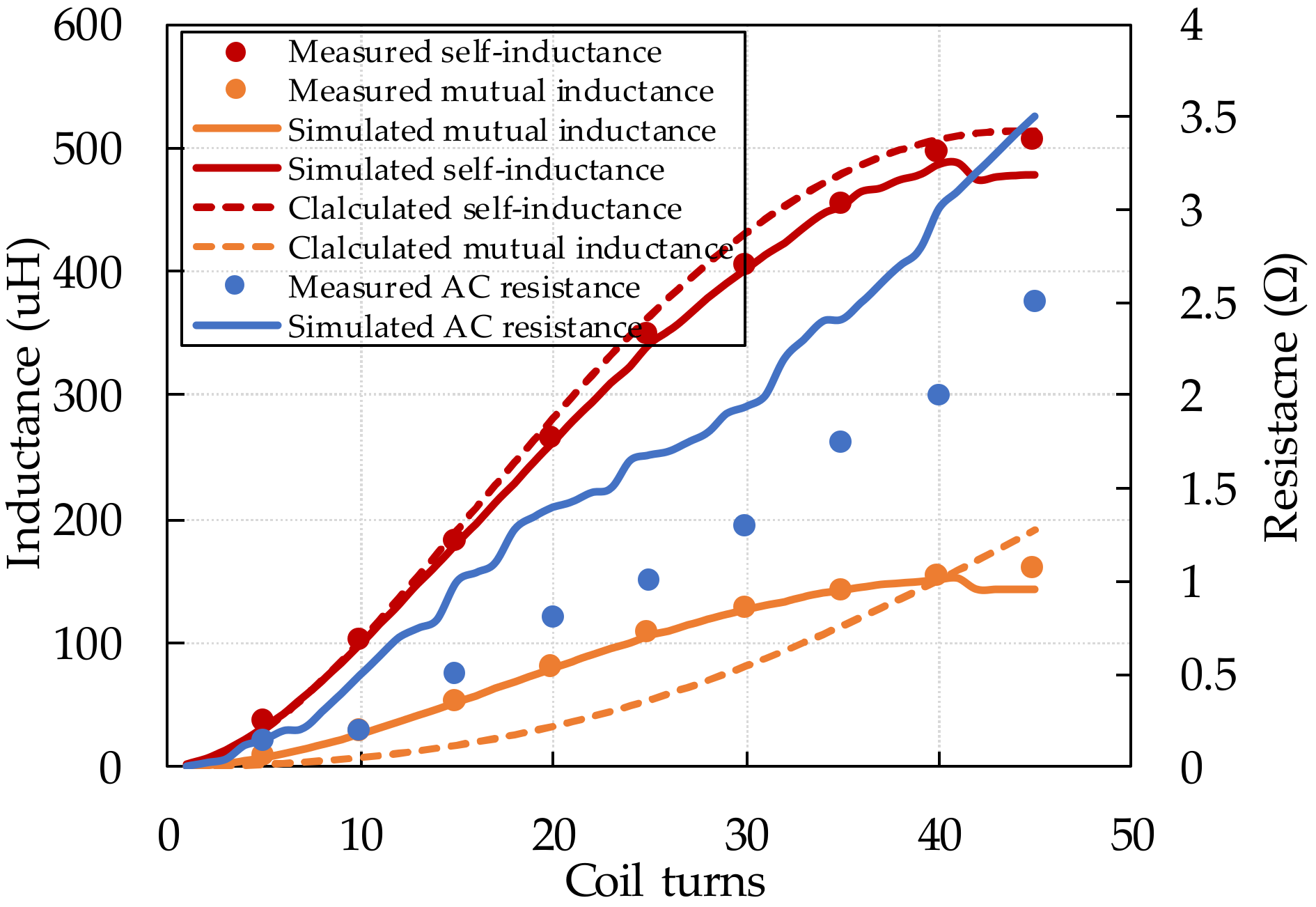
Similar to the analysis in effects of the coil outer radius, it can be found out from Figure 10 that when the outer radius of the coil is fixed, with the coil-turns increasing (inner radius decreasing), the self-inductance, mutual inductance and AC resistance of the coil will all increase.
The relationship between the coil turns/inner radius and the system performance in this case is shown in Figure 11. The calculated and measured system performance trends are consistency to each other. The output power reaches a peak value when the coil-turns is around 2 turns, and the maximum output power will be high to 7344 W in the calculation. From 2 turns onwards, the more coil-turns is, the less transferred power will be. The blue curve and scatters describe the coil-system efficiency changing trends with coils turns increasing. From Figure 11, it can be found that with the coil-turns increasing, the coil-system efficiency will increase firstly and then decrease because the coil-system efficiency is dominated by the mutual inductance and then the AC resistance. The maximum achievable coil-system efficiency occurs at around 7 coil turns in the calculation with 88% efficiency and 845 W output power. In the experiments, the coil-system efficiency can be improved from 62.6% with fully tight-wound coils to 82.6% by decreasing the coil turns to 10 and now the inner radius is 240 mm, and the output power can be increased to 130 W. In the experiments, it can be found a relative balance coil-turns (5 turns) which can achieve relative high coil-system efficiency (78.6%) and output power (1100 W).
Besides, it can also be found out that when the outer radius of the circular flat spiral coil is fixed, the maximum coil-system efficiency can be achieved (88%) is much higher than the maximum achievable coil-system efficiency with inner radius fixed coils (75.2%) even with less coil turns, 7 turns and 27 turns, respectively. And over a certain coil-turns, the more turns of the coil are, the poor performance of the WPT system will be.
3.3. Loosely-Wound: Effects of Channel Width and Coil Turns
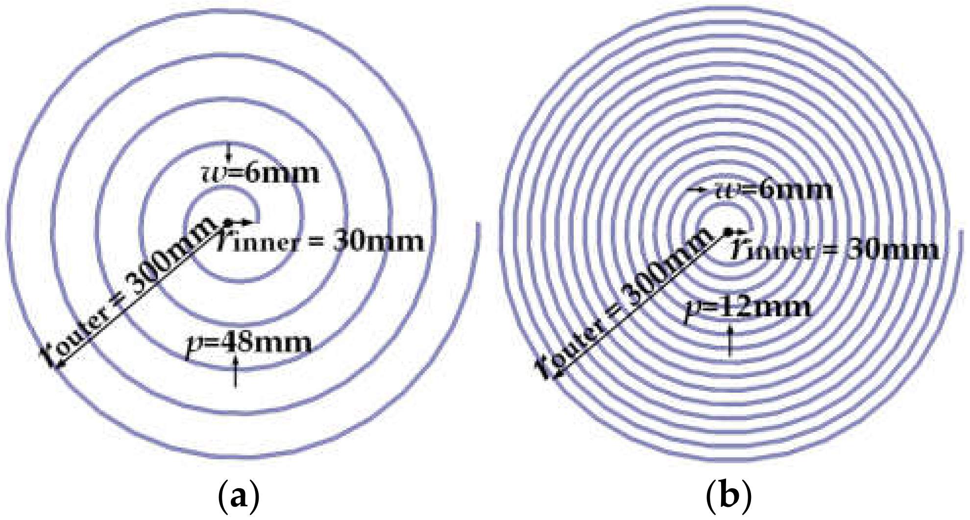
It has been derived from Section 3.1 and Section 3.2 that for fixed inner or outer radius coils, increasing the coil turns can effectively improve the coil-system efficiency in a two-coil WPT system, while too many coil-turns will in turn seriously affect the coil-system efficiency because of the rapidly increased AC resistance of the coils. As the previous analyses in Section 3.1 and Section 3.2 are both based on tightly-wound coils, while the loosely-wound coil is another option, which can help to reduce the AC resistance of the circular flat spiral coils. Therefore, in the followed two Subsections, the effects of the channel width will be studied. In this case, the inner radius and outer radius of the coil are both fixed, the channel width will be adjusted by tuning the coil-turns, therefore, coil-turns can still be used to reflect channel width changing, the coil-system physical characteristic and the WPT system performance. With fixed inner and outer radius, the channel width will increase from zero to 300 mm and this will lead the turns of the coil decrease from 45 to 1. In the experiments, coil turns will increase from 5 turns to 45 turns with 5 turns step to simplify the experiments. Figure 12a,b describe 5 turns coil and 15 turns coil respectively in this case, obviously, the more coil-turns is, the more intensive and heavy of the coil will be.
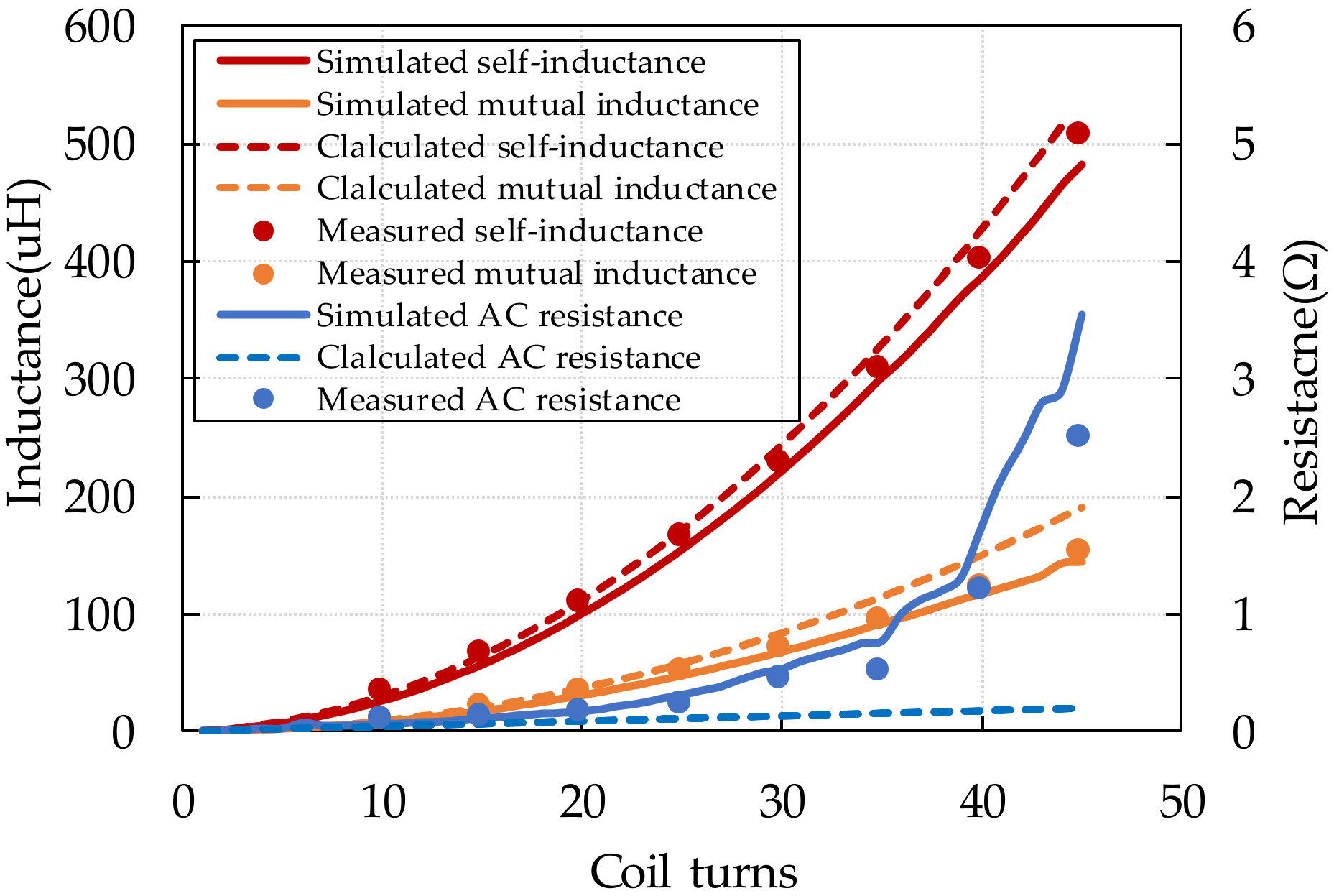
As analysed in Section 2.2, when the coil is loosely-wound, the AC resistance can be approximately calculated by the by Kaiser as Equation (17), therefore, the calculated AC resistance will be added in the later analyses to validate the completed coil-system physical model. The relationship between the coil-turns and the coil physical parameters is shown in Figure 13. It can be derived that in this case, with the coil turns increasing (channel width decreasing), the self-inductance, the AC resistance and the mutual inductance will all increase because the coil is becoming more and more concentrated. Besides, when the coil-turns is less than 20 turns, the calculated AC resistance is close to the measured values but with the coil-turns continues increasing, the proximity effect will seriously affect the coils’ AC resistance, it can also be found out that when the coil-turns is less than 35 turns, the increasing rate of the mutual inductance and the AC resistance is close to each other, but when the coil-turns is more than 35 turns the AC resistance will increase rapidly caused by the proximity effect.
The relationship between the coil turns/channel width and the system performance in this case is shown in Figure 14. From the calculation results, it can be seen that to the power transfer amount, there is still a peak value corresponding to the coil turns at around 5 turns, after 5 turns, the transferred power will be smaller and smaller with fixed other system parameters. The blue curve and scatters stand for the coil-system efficiency changing trends with coils turns increasing, with the coil turns increasing (channel width decreasing), the coil-system efficiency will increase firstly and then decrease, it can also be seen that after 20 coil-turns, because of the obviously increased AC resistance, the coil-system efficiency starts to decrease, and it will decrease sharply after 35 coil-turns because the AC resistance is rapidly increased after 35 coil turns (Figure 13), which gives more evidently explanation that the relative increasing rates of the mutual inductance and AC resistance will seriously affect the coil system efficiency.
Besides, the maximum achievable coil-system efficiency occurs at 17 coil-turns in the calculation is 91.4% with 290 W output power. In the experiments, the coil-system efficiency can be improved from 62.6% with fully tight-wound coil system to 87.76% by loose-wound coil while the channel width is 7.5 mm with 20 turns. In the experiments, the maximum achieved power transfer amount is 962 W when the coil is 10 turns and the coil-system is also a relative high value at 84%.
Therefore, when the outer radius and inner radius of the coil are fixed, by adjusting the channel width of the coil, the WPT system performance can be effectively improved. And when the channel width of the coils is less than a certain value (7.5 mm in this study), the more concentrated the coil is, the worse performance of the WPT system will be.
3.4. Loosely-Wound: Effects of Channel Width and Inner Radius
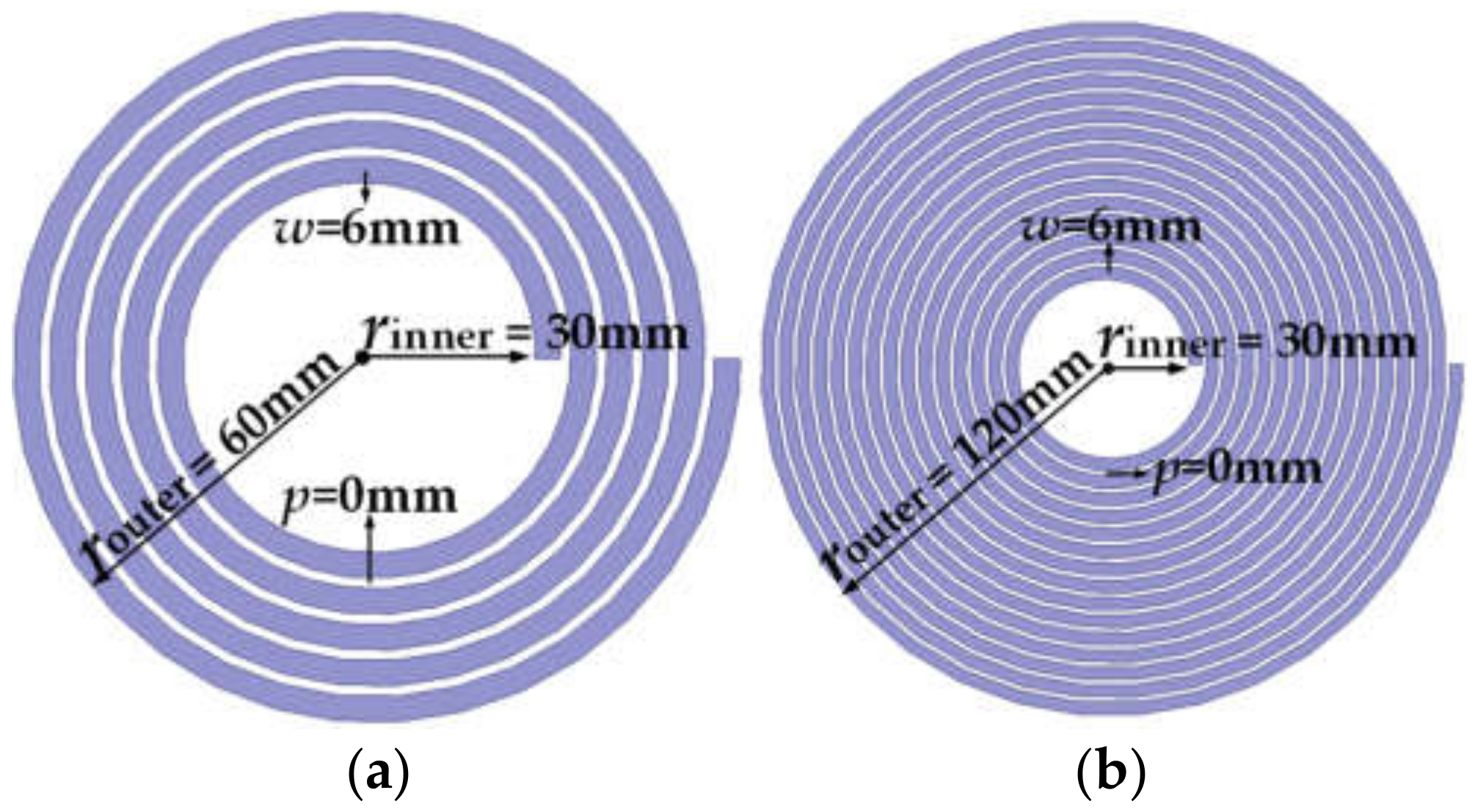
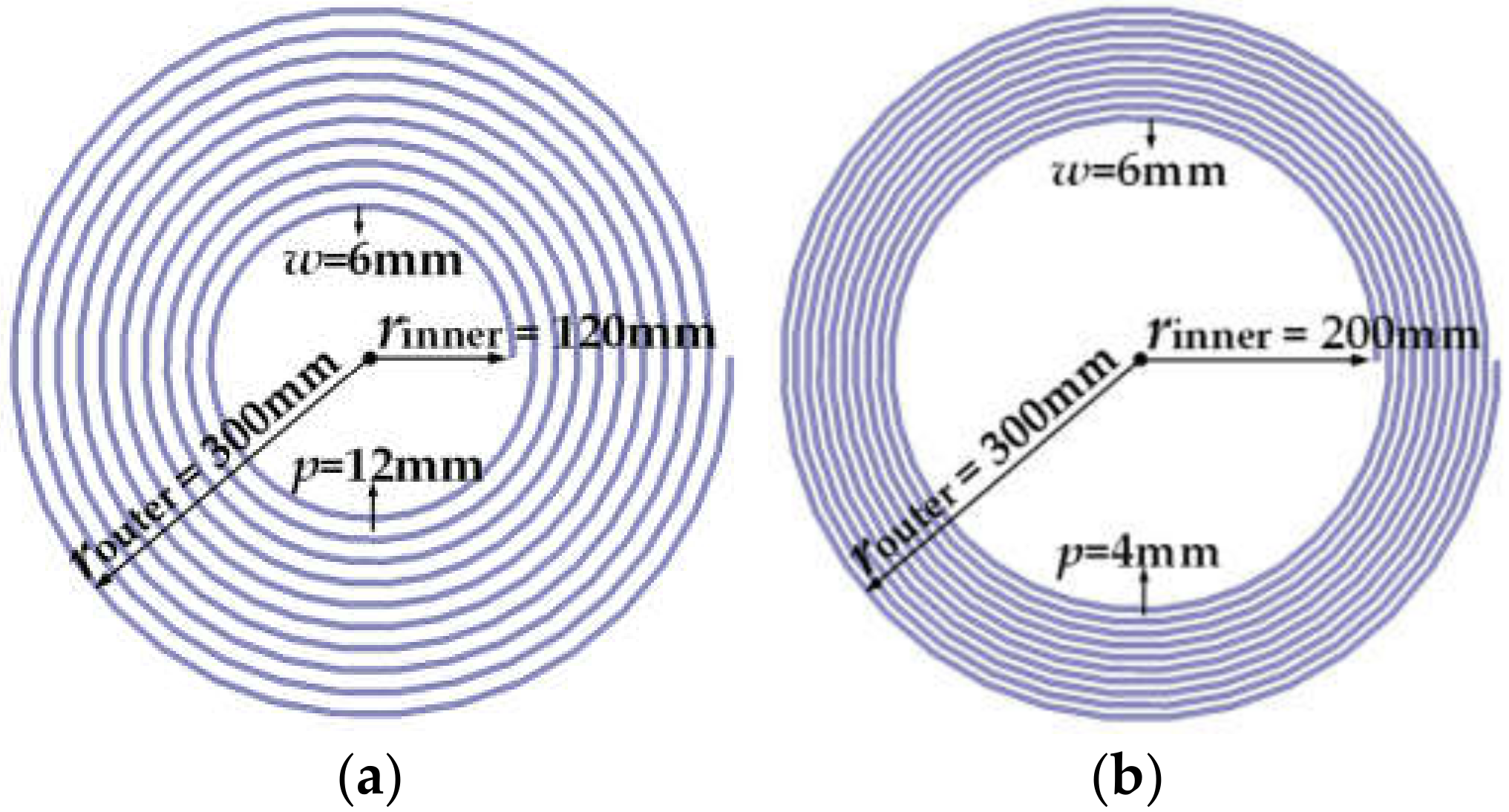
While all the previous analyses are based on turn number changeable coils, when the number of coil-turns is fixed, the structure of the coil can be also changed by adjusting the relative relationship between the channel width and inner radius to keep a constant outer radius of the coil. From previous analysis, it can be found that when the coil-turn is around 10 turns, the coil-system efficiency could be a relative high value with fixed outer radius. Therefore, in this case, the outer radius of the coil is set to be 300 mm with 10 coil turns. And the inner radius will increase from 30 mm to 240 mm with the channel width decrease from 21 mm to zero. To simplify the experiments, the inner radius of the coil will increase with 40 mm step from 40 mm to 240 mm in the experiments.
Figure 15a,b describe 120 mm inner radius coil and 200 mm inner radius coil respectively in this case. It is obviously that the larger of the inner radius is, the intensive of the coil will be and the smaller of the inner radius is, the larger of the effective area will be.
The impacts caused by the inner radius on the coil-system physical parameters and the system performance in this case can be derived as shown in Figure 16 and Figure 17 respectively. From Figure 16, it can be seen that for the self-inductance and the mutual inductance, the calculated results, the simulated results and the measured values matched well with each other, which is similar to the previous three cases, but to the AC resistance, only when the channel width is relatively large, the calculated AC resistance is close to the simulated and measured results. That is because the smaller the inner radius is, the larger the channel width will be, which will result in weaker proximity effect. As the mathematical calculation of the AC resistance of the coils used in this case is based on Kaiser Function (Equation (17)), the weaker the proximity effect is, the closer the calculated results and the measured results will be. Besides, it can also be found that with the inner radius increasing (channel width decreasing), to the coil-system physical parameters, the self-inductance, mutual inductance and AC resistance of the coil system will all increase, but the mutual inductance only increases slightly because with the increase of the inner radius, the inner hole of the coil will be larger and larger and the effective area of the coil will be smaller and smaller. And it should also be noted that the unit of the AC resistance of the coil is milliohm, therefore the AC resistance also change slightly in value.
For the system performance shown in Figure 17, the coil-system efficiency can nearly keep constant because the mutual inductance and AC resistance only changes slightly in this case. This is because the coil-system efficiency is only affected by the mutual inductance and the parasitic resistance of the coil-system when the resonant frequency and load resistance hold constant (Equation (9)), therefore, in this case, the coil-system efficiency can nearly keep constant benefiting from the slightly changed mutual inductance and AC resistance. Regarding the amount of power transferred, it will continue to decrease because of the rapidly and obviously increased coil self-inductance. In the experiments, the coil-system efficiency can be improved to 91.2% by loosely-wound coil while the inner radius is 200 mm, but the transferred power amount will decrease to 224 W, while the maximum achieved power transfer amount is 1357 W with 85.94% coil-system efficiency when the inner radius is 40 mm in the experiments, which is a more balanced choice considering the power transfer efficiency and capacity simultaneously.
Compared to the previous three studies, the calculated results are much closer to the calculated results as the AC resistance is in milliohms which will have less effects on the prediction of the WPT system performance. It means that as long as the self-inductance and mutual inductance can be accurate predicted, the system performance can also be accurate predicted for loosely-wound coil systems, which is very useful in the design process of a new WPT system. And a conclusion can be derived that when the outer radius and coil-turns of the coil are fixed, adjusting the inner radius of the coil, the output power of the WPT system can be adjusted with slightly impacts on the coil-system efficiency within limits.
4. Comparison and Discussion
In order to find out which method is the best choice for achieving a better system performance and which one is more suitable for a certain requirement, a comparison is made firstly among the first three methods as introduced in Section 3.1, Section 3.2, Section 3.3, as these three tuning methods to limit the maximum outer radius of the circular flat spiral coil in a certain value can all be presented by coil-turns changing, therefore, the system performance can be made a fair comparison for these three methods. It has been analysed in Section 2 that the transmitted power in the primary side, the received power in the secondary side and the coil-system efficiency are all determined by the coil-system physical parameters (Equations (7)–(9)) with a given resonant frequency and load resistance, therefore, the relationship between the coil designs and the system performance will be decided by the relative changing rate of the coil-system physical parameters when the design parameters of the coils change.
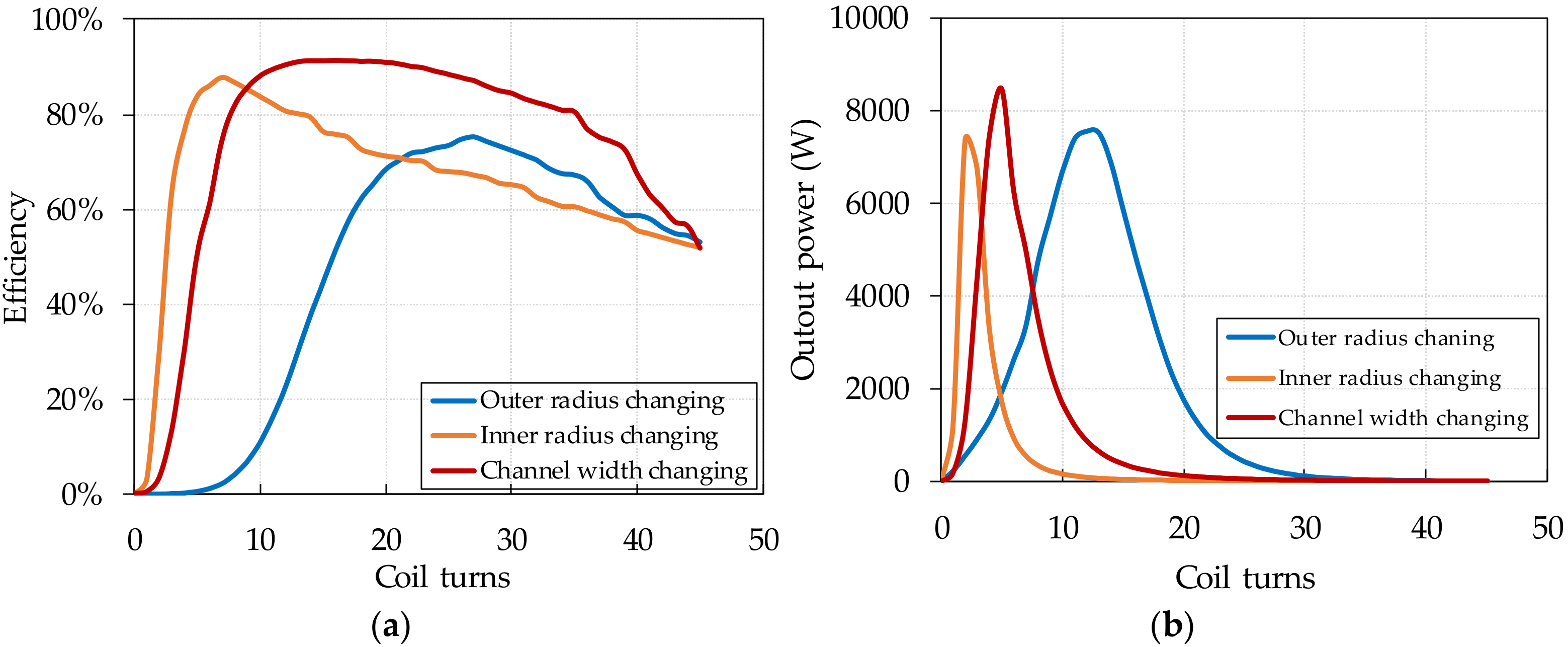
As shown in Figure 18a, the calculated coil-system efficiency is selected to be the optimization objective because the curves are more complete compared to the experiment results. It can be found from Figure 18a that in the initial state of the coil turns increasing, all these three methods can improve the coil-system efficiency greatly benefiting from the increased mutual inductance, while with the coil turns continuing increase, the coil-system efficiency will decrease because the loss in the coil will be too large compared to the total input power suffering from rapidly increased coil parasitic resistance. It can also be seen that, for tightly-wound coils (blue and orange curves), when the coil-turns is less than 22 turns, changing the inner radius with fixed outer radius (orange curve) can enjoy higher coil-system efficiency; when the coil can be loosely-wound (red curve), the coil-system efficiency of the loosely-wound coils are always higher than fixed inner radius tightly-wound coils (blue curve), and when the coil-turn is more than 9 turns, the coil-system efficiency of the loosely-wound coils (red curve) can be higher than tightly-wound coils with fixed outer radius (blue curve and orange curve), because the parasitic resistance of the loosely-wound coils is much smaller than the tightly-wound coils when the coil-turns increases over a certain value.
Regarding to the system output power (Figure 18b), for the three different conditions, they have similar trends. With the coil-turns increasing, there will always exist a peak output power of the WPT system because of the impedance matching principle. And when the outer radius of the coil is not strictly required (blue curve), the coil needs more turns to output maximum power. When the coil outer radius is specified (orange and red curves), changing the inner radius (orange curve) can achieve its peak output power with least coil turns, but changing the channel width (red curve) can achieve highest peak output power which is determined by the relative relation between the load resistance and the coil-system physical parameters because of the impedance matching principle.
While when all the four methods to keep the coil in a limited size are took into account at the same time, a comparison table can be derived as Table 1 in terms of maximum achievable coil-system efficiency, maximum achievable system output power and the most balance design considering the coil-system efficiency and the system output power simultaneous. From Table 1 and the conclusions in Section 3, it can be found out that with fixed coil-turns (10 turns in this work), by adjusting the inner radius and channel width can help the WPT system achieve maximum coil-system efficiency, while adjusting the channel width and coil turns to keep constant coil inner and outer radius can help the system obtain maximum achieved power transfer capacity.
When the system output power and the coil-system efficiency are both needed to be considered in the design, all the four methods presented in this paper can help the system improve the overall performance compared to the fully tight-wound coil. Besides, tuning the coil inner radius with coil turns or tuning the coil inner radius with channel width can help the WPT system achieve relative better performance. Among these two choices, the former one can get a better power transfer capacity with slightly sacrificing the coil-system efficiency, the later one can achieve a better efficiency performance but a slightly worse power transfer capacity performance. According to Equations (8) and (9), it can be found out that the coil-system is not related with the DC input voltage, while the output power is in direct proportion to the DC input voltage, therefore, tuning the coil inner radius and channel width simultaneous is the most balance choice when the system output power and the coil system efficiency are both considered in the design, but when the required output power is a relative high value, the required DC input voltage will be accordingly higher, and the voltage stress on the power devices and the compensation capacitors should also be considered in the system design.
It should also be noticed that in this work all the calculation and comparison are based on uniform system parameters, i.e., load resistance, DC input voltage, coil-to-coil distance, however, when the DC input voltage and the coil-to-coil distance are held constant, changing the load resistance can also change the coil-system efficiency and system output power according Equations (8) and (9) respectively. Therefore, for a particularly designed coil, there will be a certain load resistance corresponding to a maximum coil-system efficiency or a maximum system output power. Besides, the coil optimization work presented in this work is based on fixed resonant frequency, when the resonant frequency changes, the conclusion may change too, but the analysis concept is still suitable for any resonant frequency designed WPT systems. And when the other system parameters including resonant frequency, coil-to-coil distance, load resistance are adjustable, there will be much more comparisons that need to be done to establish a best performance WPT system. Additionally, it should also be noticed that all the studied coil designs are based on uniform density distribution and the assumption in each subsection, and if the coil design parameters are not designed as uniform distribution or the assumptions cannot be satisfied, it needs further analysis. Furthermore, the ferrite is not considered in this study, as the relative position and size between the coils and the ferrite bars/plates will change with the changing of the coil-design, which will lead to unfair comparisons in this study. But when the optimized coil is derived through this work, adding the ferrite can further improve the wireless power transfer efficiency.
5. Conclusions
This paper analyzed the relationship between the circular flat spiral coil design parameters and the WPT system performance based on the coupled circuit theory and the physical model of the coil-system. In order to improve the system performance regarding to the coil-system efficiency and power transfer amount, within limited size and fixed coil-to-coil distance, design parameters of the coil including outer radius, inner radius, channel width and coils turns are detailed studied. The experimental results and the theoretical calculation/simulation results show that coil structure have a strong impact on the system performance even with same coil size. To tightly-wound circular flat spiral coils, increasing the coil turns in a certain range, the coil-system efficiency can be improved, but too many coil turns will cause more losses in the coil-system because of the rapidly increased parasitic resistance which will limit the coil-system efficiency. While when the coil is loosely-wound, the coil-system efficiency can be greatly improved compared to the tightly-wound coils. If the coil turns and outer radius are both fixed, by adjusting the channel width and inner radius can tune the system output power with slightly impacts on the coil-system efficiency to satisfy a certain requirement. To the power transfer capacity, there always exists a maximum point corresponding to the maximum output power theorem. It can also be found out that the over high coil self-inductance will serious limit the power transfer capacity with other system parameters hold constant. Therefore, according the wireless power transfer capacity and coil-system efficiency requirements, the coil need to be carefully designed. Even though this paper only focus on the circular flat spiral coils, the analysis concept is also suitable for optimizing any other coil structures such as square flat spiral coils or double D pads, and the analyses in this work can help to design a specific output power and coil-system efficiency requirements system.
Author Contributions
X.L. wrote the paper and designed the experiments; C.X. shared his experience and knowledge in wireless power transfer technology; X.Y. shared his experience and knowledge in power electronics.
Funding
This work was supported by the National Natural Science Foundation of China (Grant No. 51777210) and the Jiangsu Natural Science Foundation (Grant No. BK20171190).
Conflicts of Interest
The authors declare no conflict of interest.
References
- Covic, G.A.; Elliott, G.; Stielau, O.H.; Green, R.M.; Boys, J.T. The design of a contact-less energy transfer system for a people mover system. In Proceedings of the PowerCon 2000, International Conference on Power System Technology, Perth, WA, Australia, 4–7 December 2000. [Google Scholar]
- Mecke, R.; Rathge, C. High frequency resonant inverter for contactless energy transmission over large air gap. In Proceedings of the 2004 IEEE 35th Annual Power Electronics Specialists Conference, Aachen, Germany, 20–25 June 2004. [Google Scholar]
- Liu, X.; Hui, S.Y.R. Optimal design of a hybrid winding structure for planar contactless battery charging platform. IEEE Trans. Power Electron. 2008, 23, 455–463. [Google Scholar]
- Li, Y.; Mai, R.; Lin, T.; Sun, H.; He, Z. A novel WPT system based on dual transmitters and dual receivers for high power applications: Analysis, design and implementation. Energies 2017, 10, 174. [Google Scholar] [CrossRef]
- Budhia, M.; Boys, J.T.; Covic, G.A.; Huang, C.Y. Development of a single-sided flux magnetic coupler for electric vehicle IPT charging systems. IEEE Trans. Ind. Electron. 2013, 60, 318–328. [Google Scholar] [CrossRef]
- Zaheer, A.; Hao, H.; Covic, G.A.; Kacprzak, D. Investigation of multiple decoupled coil primary pad topologies in lumped IPT systems for interoperable electric vehicle charging. IEEE Trans. Power Electron. 2015, 30, 1937–1955. [Google Scholar] [CrossRef]
- Bosshard, R.; Muhlethaler, J.; Kolar, J.W.; Stevanovic, I. The η-α-Pareto front of inductive power transfer coils. In Proceedings of the 38th Annual Conference on IEEE Industrial Electronics Society, Montreal, QC, Canada, 25–28 October 2002; pp. 4270–4277. [Google Scholar]
- Fernandez, C.; Garcia, O.; Prieto, R.; Cobos, J.A.; Gabriels, S.; Borght, G. Van Der Design issues of a core-less transformer for a contact-less napplication. In Proceedings of the Seventeenth Annual IEEE Applied Power Electronics Conference and Exposition, Dallas, TX, USA, 10–14 March 2002. [Google Scholar]
- Lyu, Y.L.; Meng, F.Y.; Yang, G.H.; Che, B.J.; Wu, Q.; Sun, L.; Erni, D.; Li, J.L.W. A Method of Using Nonidentical Resonant Coils for Frequency Splitting Elimination in Wireless Power Transfer. IEEE Trans. Power Electron. 2015, 30, 6097–6107. [Google Scholar] [CrossRef]
- Raju, S.; Wu, R.; Chan, M.; Yue, C.P. Modeling of mutual coupling between planar inductors in wireless power applications. IEEE Trans. Power Electron. 2014, 29, 481–490. [Google Scholar] [CrossRef]
- Mutashar, S.; Hannan, M.A.; Samad, S.A.; Hussain, A. Analysis and optimization of spiral circular inductive coupling link for bio-implanted applications on air and within human tissue. Sensors 2014, 14, 11522–11541. [Google Scholar] [CrossRef] [PubMed]
- Sampath, J.P.K.; Alphones, A.; Kenneth, L.Y.Y.; Vilathgamuwa, D.M. Analysis on normalized distance and scalability in designing wireless power transfer. In Proceedings of the 2015 IEEE PELS Workshop on Emerging Technologies: Wireless Power, Daejeon, Korea, 5–6 June 2015. [Google Scholar]
- Zargham, M.; Gulak, P.G. Maximum achievable efficiency in near-field coupled power-transfer systems. IEEE Trans. Biomed. Circuits Syst. 2012, 6, 228–245. [Google Scholar] [CrossRef] [PubMed]
- Kesler, M. Highly Resonant Wireless Power Transfer: Safe, Efficient, and over Distance. WiTricity Corp. Available online: http://large.stanford.edu/courses/2016/ph240/surakitbovorn1/docs/kesler.pdf (accessed on 19 October 2018).
- Miller, J.; Daga, A. Elements of Wireless Power Transfer Essential to High Power Charging of Heavy Duty Vehicles. IEEE Trans. Transp. Electrif. 2015, 7782, 1. [Google Scholar] [CrossRef]
- Roskopf, A.; Bar, E.; Joffe, C. Influence of inner skin- and proximity effects on conduction in litz wires. IEEE Trans. Power Electron. 2014, 29, 5454–5461. [Google Scholar] [CrossRef]
- Lopez-Villegas, J.M.; Samitier, J.; Cane, C.; Losantos, P.; Bausells, J. Improvement of the quality factor of RF integrated inductors by layout optimization. IEEE Transacations Microw. theory Tech. 2000, 48, 76–83. [Google Scholar] [CrossRef] [Green Version]
- Tseng, V.F.G.; Bedair, S.S.; Lazarus, N. 3D electroplated inductors with thickness variation for improved broadband performance. J. Micromech. Microeng. 2017, 27. [Google Scholar] [CrossRef]
- Boys, J.T.; Elliott, G.A.J.; Covic, G.A. An appropriate magnetic coupling co-efficient for the design and comparison of ICPT pickups. IEEE Trans. Power Electron. 2007, 22, 333–335. [Google Scholar] [CrossRef]
- Miller, J.M.; White, C.P.; Onar, O.C.; Ryan, P.M. Grid side regulation of wireless power charging of plug-in electric vehicles. In Proceedings of the 2012 IEEE Energy Conversion Congress and Exposition, Raleigh, NC, USA, 15–20 September 2012. [Google Scholar]
- Onar, O.C.; Miller, J.M.; Campbell, S.L.; Coomer, C.; White, C.P.; Seiber, L.E. A novel wireless power transfer for in-motion EV/PHEV charging. In Proceedings of the 2013 Twenty-Eighth Annual IEEE Applied Power Electronics Conference and Exposition (APEC), Long Beach, CA, USA, 17–21 March 2013. [Google Scholar]
- Wheeler, H.A. Formulas for the Skin Effect. Proc. IRE 1942, 30, 299–311. [Google Scholar] [CrossRef]
- Chan, H.; Cheng, K.; Sutanto, D. A Simplified Neumann’S Formula for Calculation of Inductance of Spiral Coil. IEEE Conf. Publ. 2000, 475, 18–19. [Google Scholar]
- Atluri, S.; Ghovanloo, M. Design of a wideband power-efficient inductive wireless link for implantable biomedical devices using multiple carriers. In Proceedings of the 2nd International IEEE EMBS Conference on Neural Engineering, Arlington, VA, USA, 16–19 March 2005. [Google Scholar]
- Duong, T.P.; Lee, J.W. A dynamically adaptable impedance-matching system for midrange wireless power transfer with misalignment. Energies 2015, 8, 7593–7617. [Google Scholar] [CrossRef]
- Waffenschmidt, E.; Staring, T. Limitation of inductive power transfer for consumer applications. In Proceedings of the 13th European Conference on Power Electronics and Applications, Barcelona, Spain, 8–10 September 2009. [Google Scholar]
- Senjuti, S. Design and Optimization of Efficient Wireless Power Transfer Links for Implantable Biotelemetry Systems. Available online: https://ir.lib.uwo.ca/etd/1154/ (accessed on 19 October 2018).
- Kim, J.; Park, Y.J. Approximate Closed-Form Formula for Calculating Ohmic Resistance in Coils of Parallel Round Wires with Unequal Pitches. IEEE Trans. Ind. Electron. 2015, 62, 3482–3489. [Google Scholar]
- Queiroz, A.C.M.D. Mutual Inductance and Inductance Calculations by Maxwell’s Method. Available online: https://deanostoybox.com/hot-streamer/TeslaCoils/OtherPapers/Antonio/maxwell.pdf (accessed on 19 October 2018).
- Zierhofer, C.M.; Hochmair, E.S. Geometric approach for coupling enhancement of magnetically coupled coils. IEEE Trans. Biomed. Eng. 1996, 43, 708–714. [Google Scholar] [CrossRef] [PubMed]
- Tortora, G.; Mulana, F.; Ciuti, G.; Dario, P.; Menciassi, A. Inductive-based wireless power recharging system for an innovative endoscopic capsule. Energies 2015, 8, 10315–10334. [Google Scholar] [CrossRef]
- Nagendra, G.R.; Covic, G.A.; Boys, J.T. Determining the Physical Size of Inductive Couplers for IPT EV Systems. Available online: https://ieeexplore.ieee.org/abstract/document/6720158 (accessed on 19 October 2018).
- Liu, X.; Clare, L.; Yuan, X.; Wang, C.; Liu, J. A Design Method for Making an LCC Compensation Two-Coil Wireless Power Transfer System More Energy Efficient Than an SS Counterpart. Energies 2017, 10, 1346. [Google Scholar] [CrossRef]
Figure 1.
Two coils SS compensated WPT system.

Figure 2.
Simplified model of the SS-WPT system.
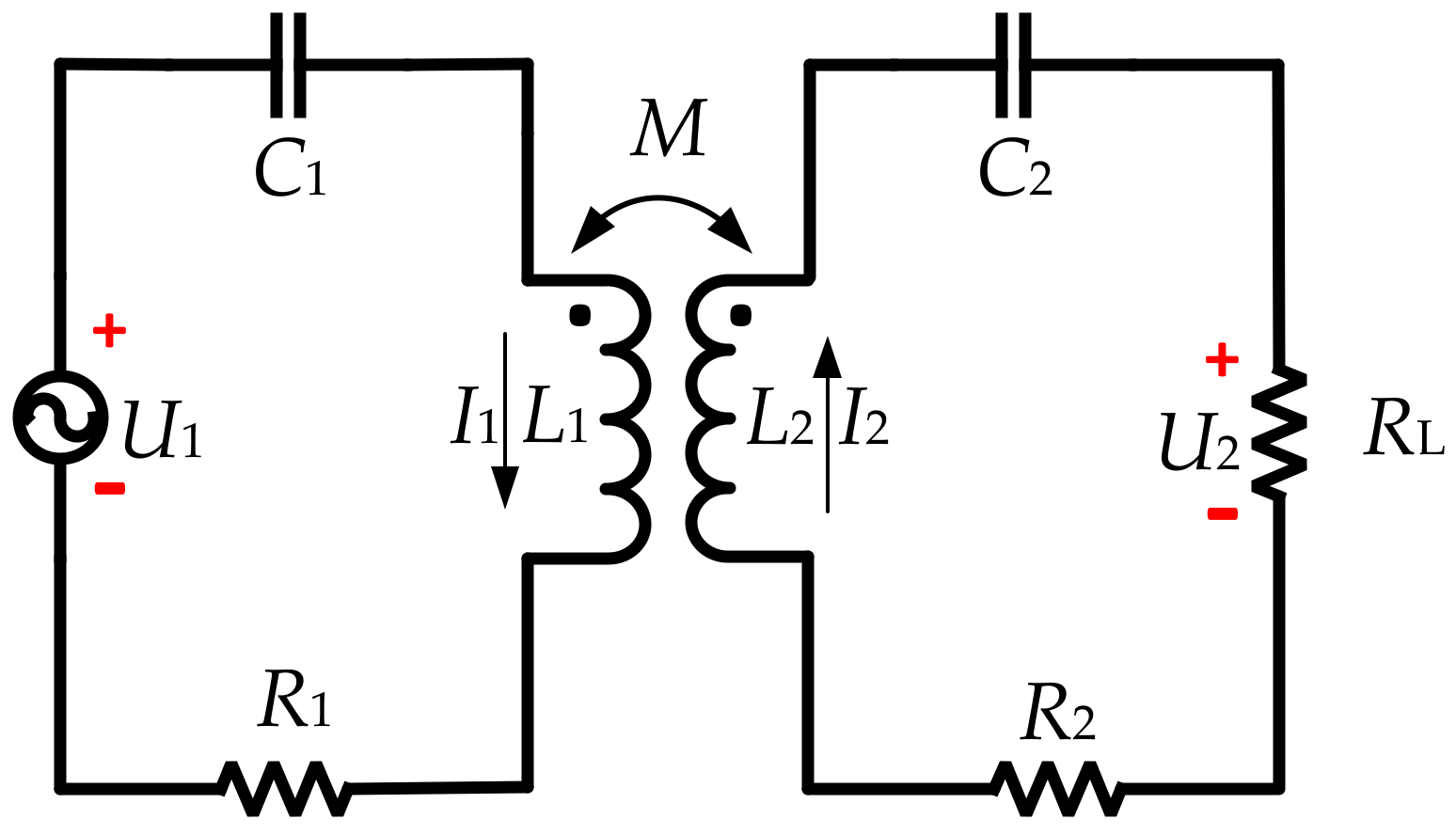
Figure 3.
Section view of a circular flat spiral coil.

Figure 4.
(a) Vertical view of a circular flat spiral coil; (b) elevation view of two horizontally coils.
Figure 4.
(a) Vertical view of a circular flat spiral coil; (b) elevation view of two horizontally coils.
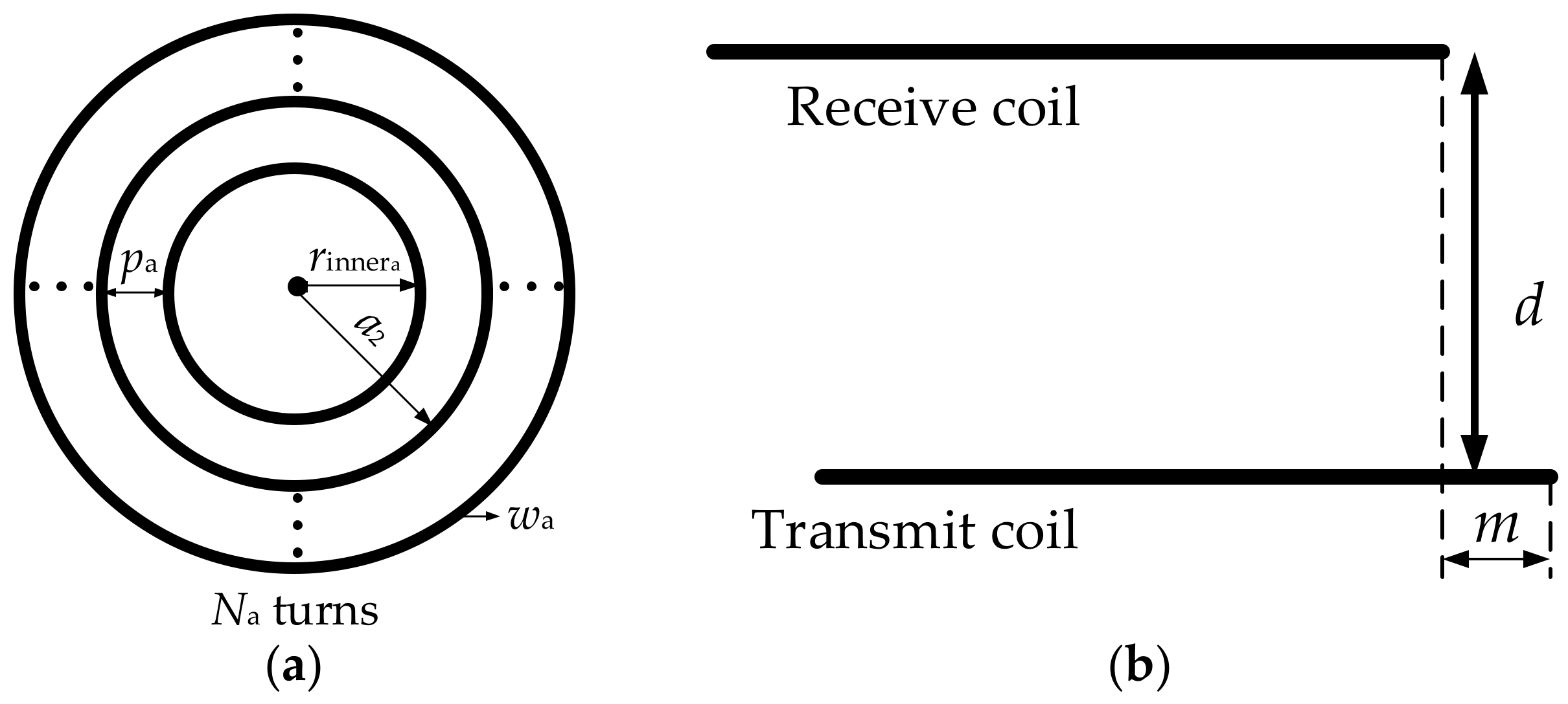
Figure 5.
Experimental Platform of the WPT System: (a) Whole system; (b) Practical coil with 16 turns, 30 mm inner radius and 10 mm channel width.
Figure 5.
Experimental Platform of the WPT System: (a) Whole system; (b) Practical coil with 16 turns, 30 mm inner radius and 10 mm channel width.

Figure 6.
Outer radius and coil turns changing: (a) 5 turns; (b) 15 turns.

Figure 7.
Relationship between coil turns and coil-system parameters with fixed inner radius.

Figure 8.
Relationship between coil turns and system performance with fixed inner radius.
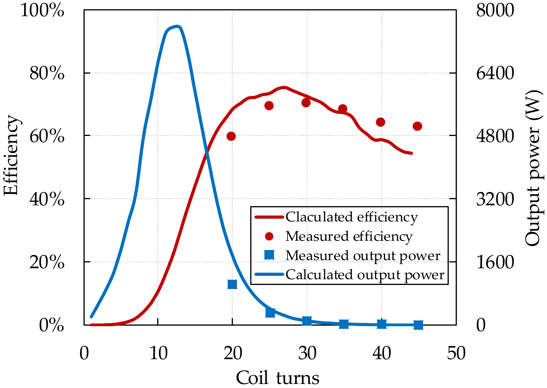
Figure 9.
Inner radius and coil turns changing: (a) 20 turns; (b) 10 turns.

Figure 10.
Relationship between coil turns and coil-system parameters with fixed outer radius.

Figure 11.
Relationship between coil turns and system performance with fixed outer radius.
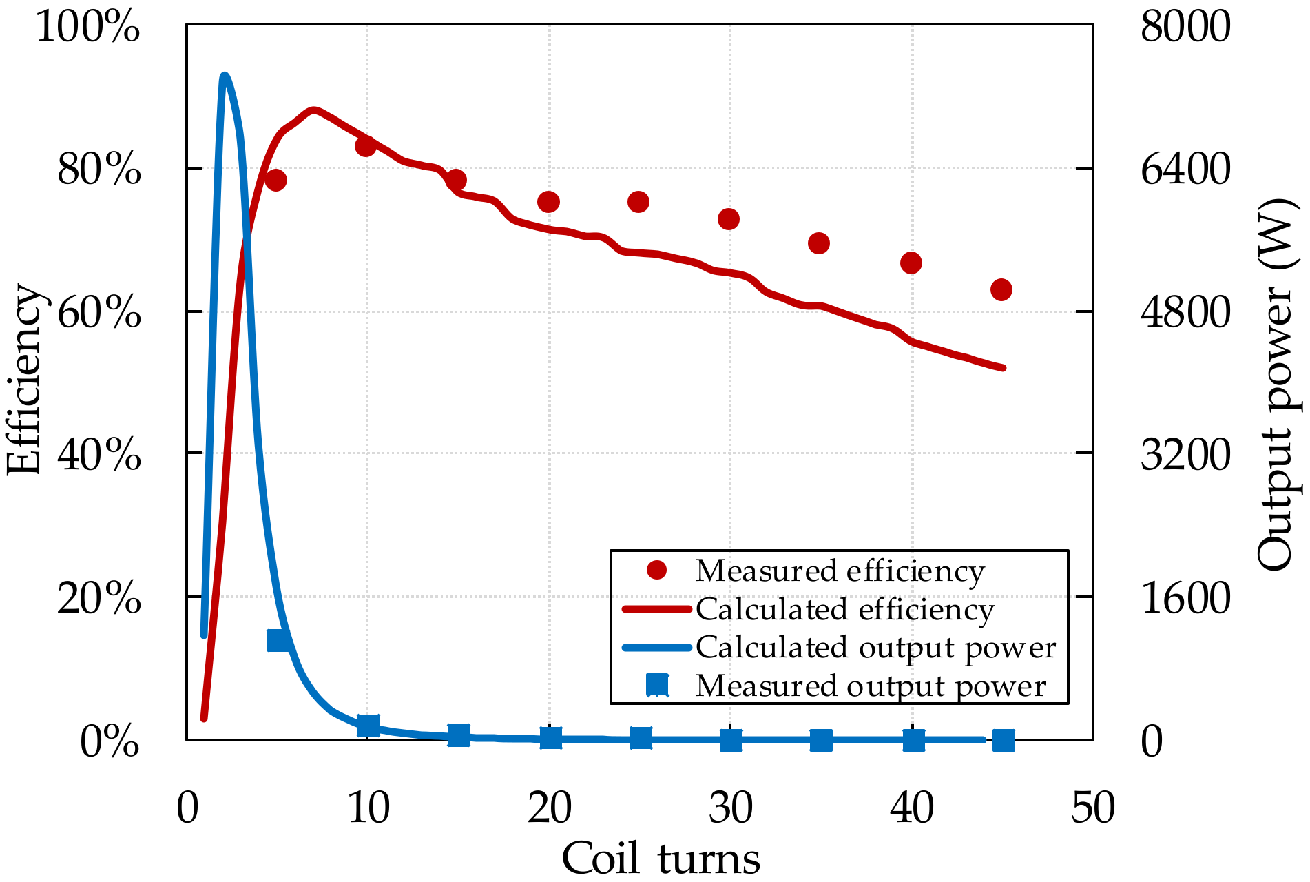
Figure 12.
Channel width and coil turns changing: (a) 5 turns; (b) 15 turns.

Figure 13.
Relationship between coil-turns and coil-system parameters with fixed inner and outer radius.
Figure 13.
Relationship between coil-turns and coil-system parameters with fixed inner and outer radius.

Figure 14.
Relationship between coil turns and system performance with fixed inner and outer radius.
Figure 14.
Relationship between coil turns and system performance with fixed inner and outer radius.
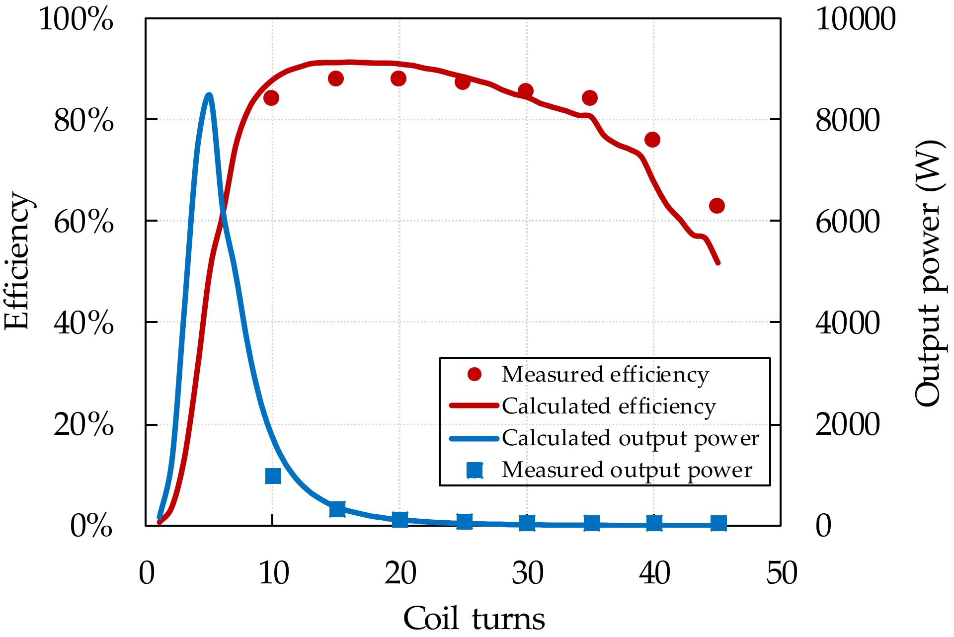
Figure 15.
Channel width and inner radius changing: (a) 120 mm inner radius; (b) 200 mm inner radius.
Figure 15.
Channel width and inner radius changing: (a) 120 mm inner radius; (b) 200 mm inner radius.

Figure 16.
Relationship between coil inner radius and coil system parameters with fixed coil turns and outer radius.
Figure 16.
Relationship between coil inner radius and coil system parameters with fixed coil turns and outer radius.
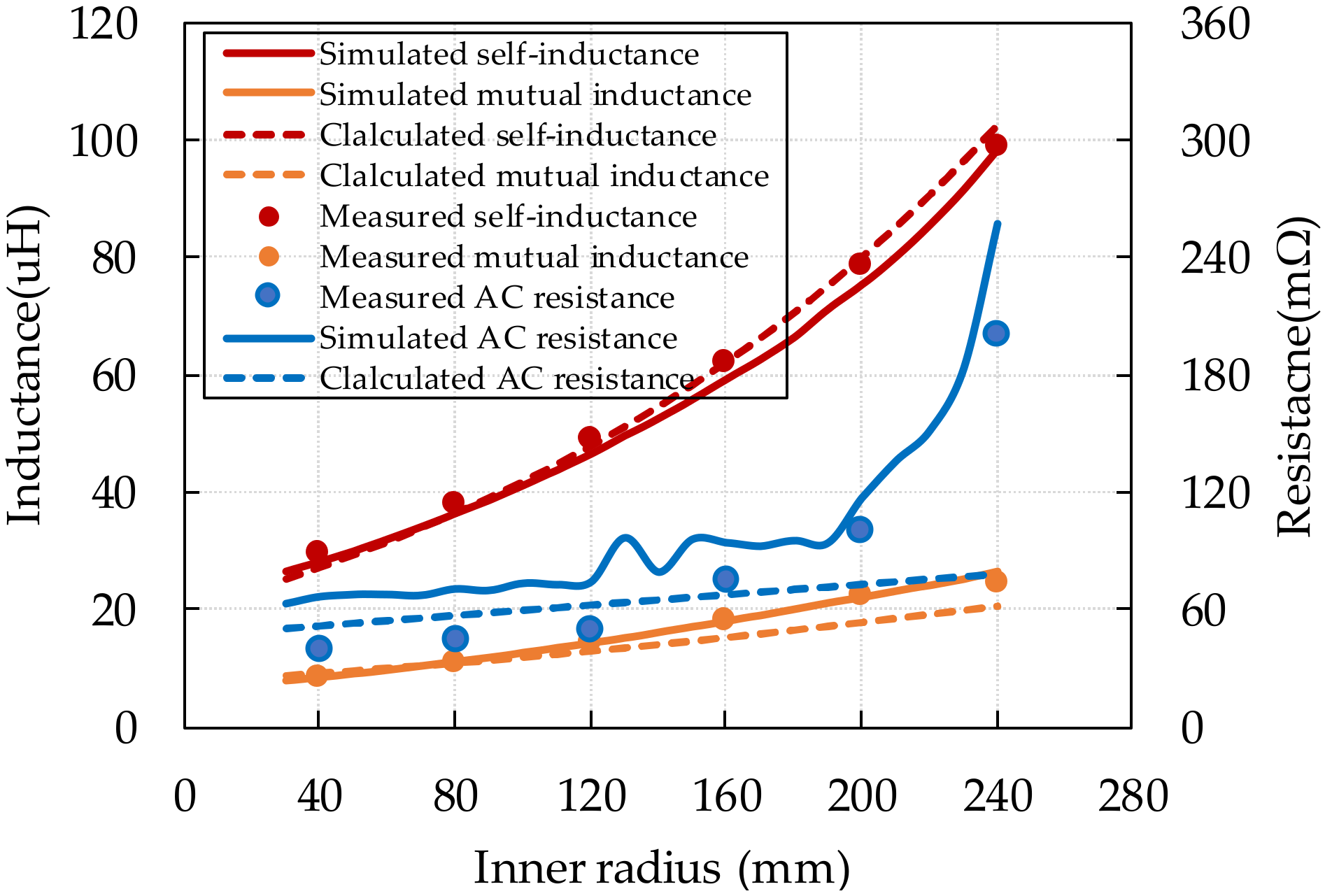
Figure 17.
Relationship between coil inner radius and system performance with fixed coil turns and outer radius.
Figure 17.
Relationship between coil inner radius and system performance with fixed coil turns and outer radius.
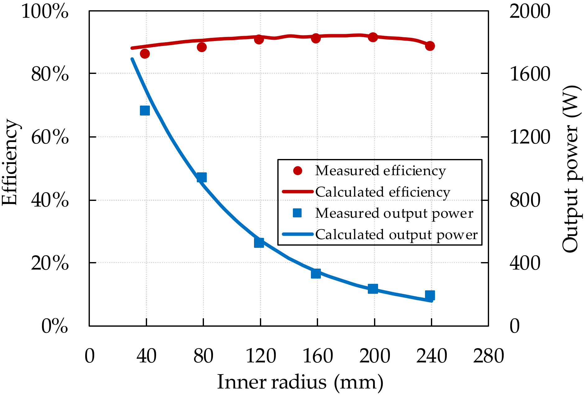
Figure 18.
Coil-system efficiency comparison among previous three methods. (a) Coil-system efficiency; (b) Output power.
Figure 18.
Coil-system efficiency comparison among previous three methods. (a) Coil-system efficiency; (b) Output power.


Table 1.
Comparison among the four coil structure design methods.
| Design Requirements | Section 3.1 | Section 3.2 | Section 3.3 | Section 3.4 |
|---|---|---|---|---|
| Maximum achievable coil-system efficiency | 75% | 87.94% | 91.4% | 92.32% |
| Maximum achievable output power | 7543 W | 7344 W | 8468 W | 1692 W |
| Most balance design (output power/efficiency) | 3941 W/57% | 3315 W/77% | 6245 W/61% | 1692 W/88% |
© 2018 by the authors. Licensee MDPI, Basel, Switzerland. This article is an open access article distributed under the terms and conditions of the Creative Commons Attribution (CC BY) license (http://creativecommons.org/licenses/by/4.0/).
Share and Cite
MDPI and ACS Style
Liu, X.; Xia, C.; Yuan, X. Study of the Circular Flat Spiral Coil Structure Effect on Wireless Power Transfer System Performance. Energies 2018, 11, 2875. https://doi.org/10.3390/en11112875
AMA Style
Liu X, Xia C, Yuan X. Study of the Circular Flat Spiral Coil Structure Effect on Wireless Power Transfer System Performance. Energies. 2018; 11(11):2875. https://doi.org/10.3390/en11112875
Chicago/Turabian StyleLiu, Xu, Chenyang Xia, and Xibo Yuan. 2018. "Study of the Circular Flat Spiral Coil Structure Effect on Wireless Power Transfer System Performance" Energies 11, no. 11: 2875. https://doi.org/10.3390/en11112875
Note that from the first issue of 2016, this journal uses article numbers instead of page numbers. See further details here.