Toward Green Vehicles Digitalization for the Next Generation of Connected and Electrified Transport Systems


1
Faculty of Engineering, Østfold University College, Kobberslagerstredet 5, 1671 Kråkeroy, Norway
2
Dipartimento Ingegneria dell’Informazione (DII), University of Pisa, via G. Caruso 16, 56122 Pisa, Italy
*
Authors to whom correspondence should be addressed.
Energies 2018, 11(11), 3124; https://doi.org/10.3390/en11113124
Submission received: 15 October 2018
/
Accepted: 8 November 2018
/
Published: 12 November 2018
(This article belongs to the Special Issue Energy Storage Systems and Power Conversion Electronics for E-Transportation and Smart Grid)
Abstract
:This survey paper reviews recent trends in green vehicle electrification and digitalization, as part of a special section on “Energy Storage Systems and Power Conversion Electronics for E-Transportation and Smart Grid”, led by the authors. First, the energy demand and emissions of electric vehicles (EVs) are reviewed, including the analysis of the trends of battery technology and of the recharging issues considering the characteristics of the power grid. Solutions to integrate EV electricity demand in power grids are also proposed. Integrated electric/electronic (E/E) architectures for hybrid EVs (HEVs) and full EVs are discussed, detailing innovations emerging for all components (power converters, electric machines, batteries, and battery-management-systems). 48 V HEVs are emerging as the most promising solution for the short-term electrification of current vehicles based on internal combustion engines. The increased digitalization and connectivity of electrified cars is posing cyber-security issues that are discussed in detail, together with some countermeasures to mitigate them, thus tracing the path for future on-board computing and control platforms.
1. Introduction
Today, about 20% of the global primary energy usage and about 25% of energy-related emissions of CO2, are due to the contribution of the transportation field [1]. Moreover, half of the emissions for transportation originate from passenger vehicles, mostly based on the internal combustion engine (ICE) propulsion [1]. One of the most promising technologies to solving the above issues is represented by electric vehicles (EVs), including hybrid EVs (HEVs), thanks to the cut of oil usage and of CO2 emissions, on a per-km basis [2].
EVs will play a major role in meetings Europe’s need for clean and efficiency mobility. The objectives set in the European Green Vehicles Initiative (EGVI) report [3] are quite ambitious; an overall efficiency improvement of the transport system by 50% in 20 years (i.e., in 2030 compared to 2010). The major EV car manufacturers have started the production and sale of EVs, with projections estimating one million EVs circulating in Europe by 2020, anticipating a significant expansion by 2030 and beyond. More than that, the sales of new electric vehicles worldwide exceeded one million cars in 2017 [4]. This market volume represents a huge growth in the sales of new electric cars, by 54% compared with 2016 [5]. In some countries, the market of electric cars is no more a niche market; for example, in Norway, the market share of electric cars, in terms of new car sales, was 39% in 2017 [6]. More than half of the global sales were in China, more than double the amount delivered in the United States [7,8]. The global stock of electric vehicles is growing rapidly and was already beyond the threshold of three million vehicles in 2017.
To reduce the emission of pollutions (e.g., CO2 and NOx), the main trend in new vehicle design is electrifying the propulsion [9,10,11,12,13,14,15,16,17,18,19]. The evolution towards electric/hybrid mobility has been accelerated by the so-called “diesel gate” in Europe and the United States [20,21], as well as by the high economic cost for cars equipped with conventional ICE, to face restrictive regulations regarding greenhouse gases. Beside low-volume premium car brands, like Tesla, several large-volume car makers announced a cut in all petrol/diesel vehicles (e.g., by 2019, all new car models from Volvo and those produced in Europe by Toyota will be fully electric and/or hybrid). By 2030, a ban of diesel car sales has been announced by several countries.
Together with the increased connectivity of the car with the smart grid, thanks to V2SG/V2I (vehicle to smart-grid/infrastructure) wireless technology, the cars of the future will be electrified, connected, shared, and autonomous. The major impacts of the current R&D activities in academia and industry will be as follows:
- (i)
- to promote the development of a new generation of EVs with a minimum autonomy of 400 km to meet customer expectations;
- (ii)
- to support the production of batteries, power components, and electrified vehicles at a low-cost and to be standardized as much as possible all over the world; and
- (iii)
- to stimulate the accessibility and ease of use of all types of charging infrastructure—public, private, or mixed.
Unfortunately, full EVs are expensive, mainly because of the cost of the battery-based energy storage. Moreover, the autonomy of full EVs is still not comparable to ICE-based ones. A full EV needs also a rethinking of the drivetrain architecture, which now should involve high voltage power buses (up to 300 V or 400 V), with extra shock protection and insulating costs, power electronic converters, battery energy storage with battery management systems, new electric machines, and new transmission schemes. Indeed, as an alternative to the classic solution of a single-engine plus a complex transmission sub-system, constructions with a dedicated motor per driving wheel (two or four) are proposed. Electrical machines on-board electrical vehicles should have power levels ranging from tens of kWs, in cases of light vehicles or in cases of one motor for each driving wheel, to hundreds of kWs. Because of large time and development costs, the widespread diffusion of electric vehicles on the market is still to come.
Hence, the hybridization of the propulsion is the most viable solution to ensure, in the short term, a smooth transition from classic petrol/diesel cars to fully electric ones. Hybrid vehicles still need the evolution of current power electronic/electric parts of ICE cars; classic alternators should evolve towards an integrated starter-generator, capable of providing torque assistance to the ICE at low rpm conditions (motor mode), or to generate electric energy when the vehicle is braking or the ICE is working at a high rpm (generator mode). The classic 12 V power bus should evolve to a 48 V bus, in order to increase the power delivered with the same current levels. Several Original Equipment Manufacturers (OEMs) already succeeded in launching/going onto the mass market with 48 V topologies, with an acceptable cost level reaching the CO2 emission targets and solving the technical challenges in areas such as battery technology, power electronics, EMC, and the electrification of further features.
The development of new tools, functionalities, and methods integrated with the controlled development of a vehicle-centralized controller will also be part of the future solutions for the next generation of EVs. For improving on the safety analysis and reduction costs, the solutions will be based on flexible user-friendly interfaces and specialized software tools, as well as on Ethernet, according to the existing ISO/IEC standards. The current trends is integrating Ethernet with other communication domains using already established technologies in the automotive industry, such as Controller Area Network (CAN), Local Interconnect Network (LIN) protocol, and Flex-Ray. These new technologies, based on digitalization and connectivity, will enable new ways to structure and design electric and electronic (E/E) architectures, such as seamless hierarchical architectures, for the next generation of cars.
As a matter of fact, digital technologies are already used in energy end-use sectors, and new technologies with the potential for widespread deployment are appearing, such as autonomous driving, intelligent domotic systems and machine learning. These platforms offer a high performance and fulfil the highest security and safety requirements [4,22].
The implementation and validation of tools under real-driving conditions based on the Internet of Things (IoT) paradigm for the over-the-air (OTA) diagnostic and flashing, and for V2SG issues, will also be part of future solutions. OTA will cut the time and cost for electronic control unit (ECU) diagnostic and reprogramming by at least 50% in case of software (SW) bugs.
To address the above issues, this paper reviews recent trends in green vehicle electrification. Particularly, Section 2 refers to the energy demand and emissions of EVs, and reviews the battery technology trends, including recharging issues and solutions, to integrate the EV electricity demand in power grids. Section 3 and Section 4 deal with the integrated electric/electronic architectures and control systems of new generations of hybrid and full electric vehicles. The increased digitalization and connectivity of cars is posing cyber-security issues, which are discussed in Section 5. Conclusions are drawn in Section 6.
2. Global EV Outlook towards GV Electrification and the Impact of Digitalization on Energy Demand
Supportive policies and cost reductions are probably going to bring important growth in the market assimilation of EVs from the outlook period to 2030. In the New Policies scenario, which adopts existing and notified policies, the number of electric light-duty vehicles (LDVs) on the road will reach 125 million by 2030 [5]. The market volume of electric LDVs on the road can grow up to 220 million in 2030, if the policy ambitions continue to rise to meet more challenging climate goals and sustainability targets, as reported in Figure 1, in the case of the EV30@30 scenario. More particularly, it is estimated that there will be 130 million battery electric vehicles (BEVs) and 90 million plug-in hybrid vehicles (PHEVs). The EV30@30 campaign, started at the Eighth Clean Energy Ministerial in 2017, redefined the electrical vehicle initiative (EVI) ambition by setting the collective ambition target for all EVI members, as a 30% market share for electric vehicles for all vehicles (except two-wheelers) by 2030. The dispatching campaign contains various implementing actions to help achieve the target, which are in agreement with the priorities and programs of each EVI country.
Fast developments in sizing battery production and reducing costs, allowed by the increasing sale of EVs, primarily driven by policies targeting LDVs, have positive disperse effects across other transport modes. Eventually, electric two-wheelers, which are not at present a prime policy focus in most regions, are planned to experience a significant increase. As matter of fact, in terms of stock share, about 40% of the world’s two-wheelers will be electric by 2030 in the New Policies scenario. China has worldwide leadership of the two-wheeler electrification market, with a continuing commitment to the electrification of mobility; however India, whose population is predicted to be as numerous as that of China in the coming years, has the ambition to electrify its two-wheelers. Europe, where fuel taxes cause a faster cost recovery over the vehicle life, is also at the top of this transition. As shown in Figure 1, if regulatory pressure is applied to better harness the full economic and environmental benefits, then a 50% global stock share can be achieved in 2030 in the EV30@30 scenario [1].
2.1. Impact of Digitalization on Energy Demand in Electrified Vehicles
Digitalization is having a major impact on the transport and automotive industry, especially on EVs and HEVs. How significant this revert will be in the future will vary for each sector, and particular, application. The transport sector is becoming smarter and more connected, improving on safety and efficiency. In electrified vehicles, connectivity is empowering new mobility dividing services. Digitalization depicts the increasing application of information and communications technologies (ICT) across the economy, including energy systems. Advances in big data analysis, analytics, and connectivity enable the trend toward greater digitalization, as follows:
- increasing volumes of data on the strength of decreasing costs of sensors and data storage;
- fast progress in advanced analytics, such as artificial intelligence (AI) and machine learning (ML);
- major connectivity of people and devices as well as faster and cheaper data transmission (4G, 5G);
- digitalization encompasses a range of digital technologies, concepts, and trends, such as AI, IoT, OTA update of SW, and the fourth industrial revolution (industry 4.0).
Mixed with the advances in vehicle automation and electrification, digitalization will result in significant but uncertain energy and emissions impacts.
2.2. Current Impact of EVs on Energy Demand
In 2017, the estimated global electricity demand from all EVs was 54 terawatt-hours (TWh) (see Figure 2), an amount corresponding to little more than the electricity demand of Greece [5]. China has worldwide leadership of this demand (91%), and its energy consumption is mainly due to two-wheelers and buses. These two modes combined account for 87% of EV electricity demand worldwide. Yet, the electricity demand for LDVs has increased the fastest since 2015 (143%), followed by buses (110%) and two-wheelers (13%).
Figure 2 shows that the approximated electricity demand from EVs in 2017 increased by 21% compared with 2016. With reference to last year (2017), the electricity demand of the EVs corresponds to 0.2% of the total global electricity consumption [5,6,19]. In countries like China and Norway, which have the largest fleet and market share of EVs, the electricity demand of EVs is still below 1% of the total demand—0.45% in China and 0.78% in Norway. As yet, the expanding numbers of EVs have had a limited impact on the electricity demand, thus providing support of confidence for the transition to greater electric mobility. As electric vehicles are started growing, they will increase electricity demand and with that will affect transmission and distribution grids.
2.3. Possible Issues and Solutions to Integrate EV Electricity Demand in Power Networks
Strong peaks characterize the demand for energy in the transportation sector in the morning and in the evening on weekdays, with limited variations across modes. Power demand also displays a morning and an evening peak in most regions, while the demand is lower during the night and in the afternoon. The low period of power demand during daytime is less visible for the summer days in warm climates, where there is a high electricity demand from cooling appliances, or in winter days in cold climates, because of the higher power demand for heating purposes.
Figure 3 shows a scenario with day changes in traffic flow in three different cities from three continents, Hong Kong (China), Long Beach (CA, USA), and Manchester (UK). Figure 3 also shows the electricity load curve of each region. The power demand and road mobility demand are both characterised by two peaks during the morning and evening hours, and a period of low demand during night time.
In all three cities, analyzed in Figure 3, as it is expected, there is a peak in traffic activity in the morning after a period of low electricity demand during the night. These specific features of electricity demand and transport activity point out that the overnight charging of EVs is well timed, before they are used in the morning. Moreover, the overnight charging of EVs has the added benefit of minimizing both the need for incremental electricity generation capacity and investment in distribution infrastructure upgrades.
The peak in electricity demand often follows the traffic peak in the evenings. Plugging EVs into the grid after the evening traffic peak may exacerbate the peak power draw. This couples with a higher risk of overloading of the power distribution network, requiring grid upgrades such as the replacement of distribution transformers and cables [23]. If not properly managed, the increased power draw at peak times could also require additional generation capacity. To avoid the economic and environmental effects of an increased peak load demand in the evenings, transferring the load to the night is advised.
Demand-side management (DSM), also called demand-side response, is an important tool that can significantly reduce the need for grid upgrades and additional generation capacity, because of the electrification of road transport, as well as facilitating the integration of renewable energy sources (RES) [5,6].
Regulators, utilities, transmission system operators, distribution system operators, and retailers are already taking DSM measures and designing policy mechanisms to ensure that the EV uptake will not overload the power grid. For EVs, DSM largely consists of the optimization of the charging time of the vehicles, shifting the loads to ensure a good match between the power supply and demand, with the aim of moving the bulk of the EV charging related power demand from the evening peak to the night. In addition to relieving the load on the distribution grid and reducing the investment needs for grid reinforcements, achieving this has the capacity to deliver a number of potential benefits, such as:
- The need for additional generation capacity is decreased by shifting EVs’ charging loads to periods where the energy demand is lower. This can lead to lower electricity prices thanks to the possibility of relying on the power produced by the generation of assets with a lower marginal price.
- Optimizing the utilization of the grid assets during the day, increasing their utilization factor and maximizing their profitability, therefore reducing their cost per kWh.
- In a more efficient way exploiting the energy produced with RES by shifting the EVs’ charging loads to periods of high output from RES. For example, exploiting the nighttime charging when the generation from wind generators is often highest, or mid-day when there are peaks from photovoltaic generation [5].
Realizing these benefits with DSM is facilitated by the implementation of a dynamic tariff policy such as time-of-use (TOU) pricing and/or real-time pricing (RTP) [24]. TOU pricing incentivizes consumers to charge EVs in a way that maximizes the power draw when electricity prices are low and minimizes it when they are high.
Dynamic pricing aims to discourage EV owners from charging their vehicle at peak times. However, it can also be used to shift the demand towards times when electricity production from RES is abundant, or to get all these benefits concurrently.
The charging process should be assisted by smart charging applications. Manufacturers such as BMW already have developed products to optimize the home charging process in an automatic way to benefit from low electricity prices [25]. DSM products may also be used to optimize the usage patterns of other residential appliances (e.g., heating and cooling) that contribute to electricity peak loads. Integrated systems may enable consumers to prioritize appliances, for instance, by temporarily reducing the electric heating to offset any additional load from charging an EV during the peak load.
DSM can also provide valuable ancillary services to the power grid, including frequency regulation, voltage support, and power factor correction, as well as the possibility to balance loads across the distribution network. The effectiveness of DSM measures could be further enhanced by a bidirectional “vehicle-to-grid” (V2G) capability. V2G is a bi-directional connection between the EV and the grid through which power can flow from the grid to the vehicle and vice-versa [25,26].
2.4. New Trends in Battery Technology and the Implication for EVs
Lithium-ion (Li-ion) storage technology prices have decreased, while the manufacturing volumes have increased. Experience in manufacturing batteries for consumer electronics has driven cost reductions to the benefit of EV packs as well as stationary storage.
Figure 4 illustrates the cost reductions comparative to the cumulative manufactured capacity across Li-ion storage technologies used in various applications. It also shows that Li-ion batteries have proved significant cost reductions since their market introduction in the 1990s.
The early development of batteries for consumer electronics (e.g., smartphones, laptops, etc.) provided invaluable experience in the production of Li-ion cells, underpinning the attainment of the cumulative production capacity of 100 gigawatt-hours (GWh) by 2010 [27], enabling the achievement of very significant cost reductions and performance improvements over the past decade. These same developments made the development of Li-ion battery packs for EVs increasingly viable.
At the state-of-art, most of battery packs used in EVs exploit the lithium-ion technology. This technology is reaching a maturity level that is enabling the design of EVs with a performance comparable to ICE vehicles. Current battery packs for light-duty applications have gravimetric energy densities of 200 Watt-hours per kilogram (Wh/kg) [28], and volumetric pack energy densities of 200–300 Watt-hours per liter (Wh/L) [29]. The lifetime of the battery is another important parameter. For EV batteries, a good proxy is the expected mileage associated with a battery’s lifetime, as well as its ability to retain a good share of its initial capacity (usually 80%).
According to the recent literature, modern Li-ion chemistry for EV batteries is able to withstand 1000-cycle degradation [30]. To compare this value to the lifetime of an ICE-based vehicle, let us assume a vehicle with a battery capacity of 35 kWh and an average consumption of 0.2 kWh/km. Withstanding 1000-cycle degradation suggests that the cycle life threshold would not be reached over the first 175,000 km of driving. Considering a car used mainly in an urban scenario for about 12,500 km/year, then 175,000 km and 1000-cycle recharging degradation means a lifetime of 14 years for the battery pack. Therefore, the lifetime of the battery is compatible with the expected lifetime for a car.
Notwithstanding the complexity of battery design and manufacturing, four key cost and performance drivers have been identified for Li-ion batteries—chemistry, capacity, manufacturing capacity, and charging speeds. The cost per kWh of the currently available battery chemistries varies because of the different energy densities and material needs.
The size of the battery packs used at the state-of-art in EVs vary considerably. For BEVs, the size of the battery packs ranges from about 20 kWh to about 100 kWh. In China, which is, as discussed before, the worldwide market leader for EVs, the three bestselling EVs have battery sizes ranging between 18.3 kWh and 23 kWh, mainly because the market in China is focused on small vehicles, and their design is focused on affordability. Instead, in Europe and North America, for mid-sized cars, the capacity of battery packs ranges between 23 kWh and 60 kWh, whereas larger cars and SUVs have battery capacities ranging from 75 kWh and 100 kWh.
As far as the current charging speed is concerned, at the state-of-art, fast chargers enable 80% recharging in less than 1 h. Such a charging speed does not constitute a challenge for current battery design. Further increasing the maximum speed of charging to ultra-fast charging (which implies working at power levels as high as 300 kW or 400 kW) is a desirable feature that would decrease the performance gap of EVs compared to ICE vehicles. However, designing batteries for ultra-fast charging has the negative effects of increasing the complexity of their design and of shortening their lifetime. Accommodating fast charging requires specific battery design considerations, such as decreasing the thickness of the electrodes. These added design constraints tend to increase the cost of the battery and to decrease its energy density. With an appropriate design and appropriately sized thermal management system, the increases in fast charging are not expected to affect the battery’s lifetime. On the other hand, an analysis conducted for the United States Department of Energy suggests that the change in battery design to accommodate 400 kW charging would nearly double the cell costs [31]. Indications from the recent assessments of battery technologies suggest that lithium-ion is expected to remain the technology of choice for the next decade (see Figure 5). The main developments in cell technology that are likely to be deployed in the next few years include the following:
- For the cathode, the reduction of cobalt content in existing cathode chemistries, aiming to reduce cost and increase energy density (i.e., from today’s Nickel Manganese Cobalt (NMC) 111 to NMC 622 by 2020, or from the 80% nickel and 15% cobalt of current Lithium Nickel Cobalt Aluminium Oxide (NCA) batteries to higher shares of nickel) [28,31,32].
- For the anode, further improvement to the graphite structure, enabling faster charging rates [28].
- For the electrolyte, the development of a gel-like electrolyte material [28].
The next generation of Li-ion batteries entering the mass production market around 2025 is expected to have a low cobalt content, high energy density, and NMC 811 cathodes. To increase the energy density up to 50% silicon can be added in small quantities to the graphite anode [28]. To contribute, better performance electrolyte salts that are able to withstand higher voltages, can be used. As reported in Figure 5, lithium-ion is assumed to remain the technology of choice for the next decade, when it is expected to take advantage of a number of improvements to increase the battery performance. According to Figure 5, other technology options are expected to become available after 2030.
3. Hybrid-Electric 48 V Vehicles
Hybrid vehicles may ensure a rapid and smooth transition from the current generation of petrol/diesel-based propulsion to new electrified mobility. HEVs may be realized by combining a downsized ICE with an electric motor, usually within 10 kW and with power DC buses up to 48 V nominal. In such cases, the on-board energy storage to provide extra energy for torque assist, or to store recovered energy when braking, can be limited to less than 1 kWh. The immediate benefit vs. current vehicle generations is fuel saving and CO2 reduction. According to this approach, an electrical machine able to work in both motor and generator modes, with power levels to 10 or 15 kW [12,17,21], can implement several “green” functions, aimed at fuel saving and/or a reduction of pollutant emissions. Among these “green” functions, it is worth mentioning the following: start-and-stop to cut ICE emissions in urban scenarios, torque assistance to improve efficiency at low-rpm regimes where an ICE is not working in optimal conditions, and regenerative braking to avoid just dissipating energy when a deceleration is needed. Besides assisting with an electric machine, the ICE for the propulsion, a saving of energy and of pollution emissions can be achieved through the electrifications of comfort and/or chassis control functions. The latter include, as an example, the electrically controlled air-conditioning compressors or the electric steering.
In this context, a belt-driven starter generator (BSG), or an integrated starter generator (ISG), replaces the conventional alternator, thus creating a parallel hybrid architecture. Figure 6 shows the layout of a BSG. The main idea is that the starter-generator electrical machines replaces the conventional alternator. In this way, there is a low impact on the layout of the engine compartment, and just the redesign of the belt tensioner is needed. Differently from the BSG solution, in the ISG solution, the starter-generator electric machine should be inserted between the ICE and the gearbox. Hence, the ISG approach requires a complete revision of the engine compartment. This is why the authors focused their work, as reported in this survey paper, on the design of a BSG electrical machine.
For hybrid vehicles using BSG or ISG machines, the classic 12 V automotive DC bus reaches its limit as follows: at 12 V, the supplied current would be above 600 A in the case of cranking (e.g., peak current at cars start). This will require cables with a high cross section, with a too high increase in wiring cost and size. To solve this issue, there is a trend toward the adoption of a 48 V DC bus technology (52 V in generator mode) for hybrid vehicles. With respect to a classic 12 V solution, the drawn current at equivalent power is reduced by a factor of four. As DC voltages below 60 V do not require electrical shock protection, adopting a 48 V DC bus does not increase the cost of the on-board electrical implant by too much. In the short term, to reduce the cost of migrating from ICE-based vehicle generation using 12 V electrical systems to a new 48 V HEV generation, most of the 12 V automotive components will be reused. As a consequence, new 48 V HEVs require the development of energy-efficient and compact DC/DC converters [20,21]. These DC/DC converters should be able to interconnect the 48 V DC domain to the low voltage supply domains required by low-power components (such as ECUs and memories and sensors). In the case of a fault and/or malfunction, the 48 V domain should be isolated from the low-voltage domain. In emerging 48 V HEVs, another issue is the design of an integrated H-bridge for rotor excitation. The integration is important for reducing the use of discrete devices, thus reducing the size, weight, and cost. In summary, the main issues of hybrid vs. ICE vehicles are the introduction of (i) BSG/ISG machines and related power drives; (ii) 48 V architecture; and (iii) DC/DC converters among the 48 V and 12 V buses to reuse most of the 12 V components.
Figure 6 shows the vehicle electrical architecture for a hybrid vehicle, including a BSG or ISG unit. The BSG or ISG unit is a mechatronic sub-system; it receives the electric power from the battery pack (at 48 V in Figure 6) plus proper command/configuration signals from the vehicle control unit (VCU). The VCU is interfaced also to local sensors, including the ignition signal, and through the main car bus it is connected to all of the other ECUs. At the state-of-art, the controller area network (CAN) is the de facto standard to connect vehicle ECUs with smart actuator and sensing units. As it will be discussed in Section 5, the fact that the BSG or ISG machine (providing torque assistance, start and stop, and electric energy generation functionalities) is connected to the CAN poses several cybersecurity issues to be addressed, as they can lead to safety issues. The core of the BSG proposed in our research work is a six-phase wounded rotor synchronous machine, showed with its dedicated electronics in Figure 7. As we detail in the literature [21], the architecture of the proposed BSG electrical machine includes a wounded rotor and a double three-phase stator. The prototype of the BSG electrical machine is shown in Figure 7. The power level of the proposed BSG electrical machine is up to 8 kW in operating conditions, with a peak of 15 kW. The adoption of two stators instead of a classic solution with two stators allows for the use of lower current levels in each stator and of smaller copper winding. The two stators in the BSG of Figure 7 are electrically shifted by 30 degrees. This solution allows for reducing the ripple on the output rectification. The new BSG electrical machine of Figure 7, within the EU project ATHENIS-3D with the Valeo company, has been integrated and tested on a commercial car—a Peugeot308 hybrid [21]. The proposed drive reaches a max speed of 20,000 rpm (no load condition), and a max torque at a low-rpm of 70 Nm, and is able to start a 1.5 L diesel engine in less than 400 ms, going from 0 to more than 1000 rpm.
The electronics of the BSG electrical machine in Figure 6 include the following two main power sections:
- -
- The stators connected to power modules, where each three-phase stator includes six MOSFETs transistors that can be controlled to work both in inverter mode or rectifier mode. The synchronous rectification mode is adopted when the power system is working in generator mode. The six MOSFETs are controlled in the DC/AC inverter mode, using a pulse width modulation/full wave (PWM/FW) technique, when the power system is working in motor mode.
- -
- The rotor current control that is managed by an H-bridge using four power MOSFETs is controlled by PWM signals. The full H-bridge approach (instead of using just a half bridge with two MOSFETs) is needed to ensure fast demagnetization in cases of load dump, and to increase safety vs. overvoltage phenomena in cases of component failures.
The control electronics of the BSG electrical machine include the following two power domains:
- -
- The 48 V domain, which is dedicated to the control of the wounded rotor and the two three-phase stators. The controller in the 48 V domain generates all of the signals needed to drive the power MOSFETs of the rectifier/inverter stages of the two three-phase stators, and to drive the power MOSFETs of the H-bridge used to control the rotor current. The 48 V domain also includes analog and digital circuits that are used to interface all of the sensors in the stator and rotor control. Examples of such sensors are phase current sensors, phase voltage sensors, rotor position sensors, stator thermal sensors, and power module thermal sensors.
- -
- The 12 V domain, which is used for the ECU.Concerning the control algorithm used for the BSG electrical machine, seen in Figure 7, a closed-loop flux vector control running in real-time on a field programmable gate array (FPGA) is the preferred solution. Differently from the classic 32 bit microcontrollers, the use of FPGA as a computing platform for BSG control ensures a better trade-off in terms of computational capability, flexibility, size, and power consumption. It is worth noting that at the state-of-art, FPGA devices are available as automotive qualified components (e.g., AECQ-100).
Another innovation discussed in this work is the use of direct copper bonding (DCB) technology for the 48 V H-bridge. The aim of the DCB usage is the reduction of the ON-resistance (“drain-source on resistance”, is the total resistance between the drain and source in a Metal Oxide Field Effect Transistor, or MOSFET when the MOSFET is “on”) of the H-bridge switches. Indeed, low ON-resistance values are needed to minimize power dissipation when the current is flowing through the H-bridge switch. The ON-resistance is due not only to the RDSON of the power MOSFETs (that can be reduced by increasing the silicon area), but also to the resistance of the connections between the power MOSFETs and the electronic board on which the devices are assembled. To achieve low ohmic transistor connections in the 48 V H-bridge, DCB technology can be adopted when designing the electronic board and assembling the devices. In the DCB approach, an interconnect plate with Al2O3 ceramic substrate and electroplated copper is used. The thickness of the electronic board is 0.38 mm. The thickness of the copper is about 0.3 mm, with a surface plating for die stacking with a 5 µm Ni and 0.03 µm Au layer. Each transistor chip is connected with four lines (two source lines and two drain lines) to the electronic board. A stress analysis has been carried out within the ATHENIS-3D EU project [21] with an AMS partner on a 48 V H-bridge, using transistors implemented in High Voltage Power MOSFET (HV-MOS) technology, with a DCB connection to the board. This stress analysis has demonstrated that the DCB technology can allow for operations at high temperatures (up to 175 °C).
The supply voltage of the H-bridge, used in Figure 7, is nominal 48 V (in generator mode the voltage is 52 V). The rotor currents are up to 12 A in nominal conditions and up to 17 A in transient conditions. The four transistors of the H-bridge are realized in AMS HV-MOS technology, with DCB on ceramic substrate, as two P-channel MOSFETs for the high side devices and two N-channel MOSFETs for the low side devices. Using P-channel MOSFETs as high side devices in the H-bridge allows for avoiding the use of complex charge-pump devices, although at the price of a higher ON-resistance vs. N-channel MOSFETs. The minimum ON-resistance is 8 mΩ for N-channel MOSFETs and 11 mΩ for P-channel MOSFETs when using a 5 V gate-source supply for the transistors. Table 1 shows a comparison of the performance parameters of the integrated H-bridge vs. the state-of-art of the integrated devices for rotor coil driving. With reference to the H-bridge in the literature [33], implemented using the same HV-MOS technology, the solution proposed in this work sustains a current 2.125 times higher and a voltage 4 times higher, whereas the ON-resistance is reduced by 6 times. The improved performance of the H-bridge proposed in this work vs. that in the literature [33] (×2.125 higher current, ×4 higher voltage, and ×6 lower ON-resistance) is justified by both the increase of the transistor area and by the adoption of the DCB approach, missing in the literature [33]. Thanks to the DCB technology, the transistors are assembled on top of the ceramic substrate. The DCB technology also allows for a reduction of the printed circuit board (PCB) size with respect to the layouts of electronic boards, where large conductive plates are placed around the chip to achieve low-ohmic contacts, as in the literature [33]. Since in this work, the electronics is coupled with the 48 V BSG machine, and the adopted technology is a low-cost one, and the DCB approach allows for a reduction of the PCB size, then the increased area of the transistors is not an issue.
4. Full Electric Vehicles
In recent years, EVs or BEVs have been gaining popularity, and one of the most important reason behind this is their contribution to reducing greenhouse gas (GHG) emissions.
EVs, including the different types of BEVs, HEVs, PHEVs, and fuel-cell EVs (FCEVs), have been becoming more commonplace in the transportation sector in the last five years. A block diagram with the main EV’s components is depicted in Figure 8. Comparing this figure for EV with that of Figure 6 (right), it is clear how full EV needs a major change in current car architectures with lot of new electronic and electrical sub-systems. This is why many leading OEM’s and suppliers are developing 48 Volt architecture, as discussed in Section 3, on the basis that it can achieve large efficiency gains at lower costs in the medium term rather than full electrification, as discussed in this section.
The main energy source of BEV is the high voltage battery, while the most important components of the EV are the electrical motors and the high voltage battery, which, together with the transmission system, builds the vehicle drivetrain architecture. These main components are assisted by a number of auxiliary subsystems, such as an ECU, a battery management system (BMS), and power electronics converters. An ECU, which can be called “e-motor control”, is liable for the electric motors operation mode. BMS, also called the battery monitoring and control unit (BMCU), supervises the storage operations, including charging and discharging states. Most EVs contain on-board single/phase or three/phase unidirectional or bidirectional chargers; hence, an AC/DC power electronic converter is required. Power electronic converters, for the charging operation mode are able to transform energy from AC to DC, while for the discharging operation mode, they should be able to transform energy from DC to AC. At the same time, the EV system operation requires other energy conversions in order to supply other subsystems. Therefore, several additional converters are needed, such as the following:
- -
- DC/DC switch/mode converters between internal LV and HV battery, to charge LV battery;
- -
- DC/DC switch/mode converters between electrical motors and HV battery system in order to provide braking energy regeneration;
- -
- AC/DC switch/mode converters and DC/DC chopper or single DC/DC converter between the alternator and the HV battery.
EVs can produce significant impacts on the environment, on the network for power system distribution, and on other related sectors. The actual power system could face huge instabilities with enough EV penetration, but with a suitable management and coordination system, EVs can be turned into a major contributor to the successful implementation of the smart grid concept.
4.1. E/E-Architecture for EVs
The physical architecture as well as the electrical and electronics (E/E) architecture will be the keys to manage the increased complexity of the third generation of EVs, which will require a faster increase in electronics, software, and communication capabilities.
The new generation of electric and autonomous driving vehicles is evolving towards a distributed connection of smart sensors, ECUs, and actuator control units (ACUs), up to one hundred devices for a premium car, with stringent requirements in terms of bandwidth, functional safety, and security. In addition, the complexity of the software, stored in the non-volatile memories of the ECUs, is continuously growing [34]; today, the number of software code lines on a premium car is reaching 100 million. Security against cyberattacks is a recent but very important issue in the transportation world. As vehicles are evolving towards autonomous driving, and the vehicle-to-X (vehicle, infrastructure, road, or pedestrian) connections and on-board vehicles networking allow for access to every ECU in a car, then a remote cyberattack can force failure in any of the key functions of a vehicle, like the control of propulsion, braking, steering, and so on. To illustrate the importance of automotive security, recent studies forecast investments in this field of up to 11 billion by 2021. By 2020, some estimates forecast that 40% of the cost of a car will be in wiring and connections. Cybersecurity issues of digitized and electrified vehicles are discussed in Section 5.
A seamless hierarchical E/E architecture for the next generation of cars is shown in Figure 9. In this architecture, the central computing platform partition the main software functions offering high performance and fulfil the highest security and safety requirements.
The advantages of this platform, shown in Figure 9, are that each ECU class has specific requirements, such that the classification is requirements-based and the system level optimization is the focus. BMW has introduced a service-oriented architecture (SOA), similar to the one in Figure 9, for the next generation of E/E architecture, with hierarchy enabled testing against interfaces using agile methods for system complexity reduction.
4.2. Power Train Design and Component Trends of EVs
The majority of European automotive manufacturers have already decided to introduce 48 V technology to reduce the consumption of their fleets and to meet the new European CO2 boundaries, which will came into force from 2021. In the near future, plug and play or start–stop systems, 48 V systems, and high-voltage electrification will all occur together in most fleets. A strong worldwide global trend towards plug-in hybrids has emerged. For instance, in China, all-electric vehicles are particularly in demand.
In Europe, 48 V systems still have their development core, although many automotive manufacturers have now recognized their advantages, and global programs have been introduced immediately after that. An analysis of the extra costs of HEVs proves that 48 V mild HEVs are only 30–50% as cost-intensive as high-voltage HEVs [35]. As such, the 48 V system represents an intelligent and, in particular, affordable supplement to full and plug-in hybrids vehicles. In addition, 48 V systems can be integrated more easily into existing vehicle powertrains and architectures, but a fewer extensive modifications are also required. Consequently, it can be anticipated that the 48 V voltage level will very quickly become established in the market.
Furthermore, to make use of hybridization, the additional 48 V system also makes it possible to have a choice of electrical components in the vehicle at higher voltages. This is significant, because the number of electrical components is continuing to expand dramatically, especially in the mid-size and luxury car markets [1,35]. In addition to that, high-power components work more efficiently at higher voltages, and converting them to the 48 V on-board power system also decreases the load on the 12 V system. Market predictions highlight the fact that 25% of newly registered cars will have an electrified powertrain by 2025, as can be seen in Figure 10, and that almost half of these vehicles will use 48 V technology.
As can also be seen in Figure 10, beginning with the year 2020 onwards, a global potential of up to four million of 48 V systems could be deployed.
Because of the different options to mechanically connect and integrate the 48 V electrical machines (usually as a starter generator in 48 V technology) into the drivetrain, and the different types of 48 V electrical machines available for selection, several powertrain topologies are achievable. The powertrain topology chosen significantly influences the performance and characteristics with which the aforementioned functions can be implemented, as well as the costs involved. Carmakers and automotive suppliers are currently analyzing and evaluating four major powertrain topologies [36,37,38]. Depending on the e-machine architecture, the topologies vary in relation to their potential for energy recovery and electrical boost capacity.
In the next-generation of EVs, power and efficiency are critical parameters, as the number of engine control units and ECUs within the cars grows exponentially. The electrical and electronic component’s models, such as electrical machines, power electronic converters, and controllers, represent the e-drivetrain system components for closed-loop tests (HIL).
4.3. High Voltage Battery Systems Technology and Battery Management
The high voltage battery system is in fact the EV energy source subsystem. As it is one of the most important components of BEV, it may require special care and handling. For instance, in the case of DC fast charging, EV’s BMS system and charging station should establish the bi-directional communication to exchange information such as the battery charging pattern, state of charge (SOC), temperature, and so on [39]. At present, the battery system is one of the most demandable and critical components of the EV system. Main issues include their weight, price, capacity, energy density, lifetime or degradation, electrical parameters, and dimensions [39,40,41,42,43]. For all of this, EV batteries’ market segment is rapidly developing and increasing, and manufacturers and e-mobility stakeholders are conscious that batteries are crucial for the sector to be further development [1,39].
The most used battery technology for EV is Lithium-ion, as already highlighted in Section 2. This battery type can be designed using various cathode and anode materials such as lithium titanate, lithium–cobalt, oxide-based, or lithium–iron–phosphorus. Li-ion promises a high energy density, lifetime, and charging cycles [1,40,41,42,43,44]. Li-ion batteries are characterized by an energy density of 130 Wh/kg, a cell voltage of 3.7 V, and their expected number of cycles (e.g., 3000), assuming that the depth of discharge (DoD) is at 80% [39]. The highest practical energy density can be achieved within the cobalt cathode (120–180 Wh/kg). Battery development is crucial for further e-mobility development. The most urgent issues include increasing the energy storage capacity, allowing for high current charging, and extending cycle lifetime, as well as improving safety and reducing cost.
The BMS handles operation of the EV battery and its functionalities are very important for the optimal use and handling of high voltage batteries. It controls the charging and discharging cycles together with the on-board or off-board charger. The control strategy is in most cases arranged for extending the battery lifetime. BMS impedes also from deep discharge and wrong charging parameters. The main important BMS tasks can be summarized as follows:
- -
- controlling/giving assistance to charging and discharging cycles, including fast charging and smart charging;
- -
- protecting battery from operating outside the admissible range;
- -
- monitoring the battery SOC and battery condition (BMS includes control of voltage, power level, temperature, SOC, state of health, current, and coolant flow);
- -
- reporting data.
The BMS system/unit contains three main subsystems, centralized, distributed, and modular parts. Centralized subsystem is based on wire connections and is a single controller connected to the battery cells. The distributed components of the BMS implies BMS on/off board battery chargers, in which each cell is equipped. Modular subsystem involves a few controllers, which carry out the operation of a certain number of cells. BMS needs to send the required data to other devices in the EV system. The main measures used for this purpose include CAN BUS, FlexRay, or direct wiring, although data transmission over the power bus or fast wireless communication based on IoT may be used.
4.4. Electric Motors and Control
It is imagined that the 48 V powertrain systems of all types will operate without the traditional 12 V generator, as the 48 V electrical machine takes over the generator function. Thanks to the higher voltage, the electrical machine’s performance and efficiency will be improved. Differently from classic 12 V generators, electrical machines in new EV generations fulfil two different functions, as they work in both regimes, as generators and starters, or rather electrical motors, to support propulsion.
Key parameters of the powertrain system include the total system load, the charging status (SOC and SOH), and the dimensioning/size of the batteries. The energy management system controls the activation of individual functions and features, such as the charge, boost, or recovery modes, in the circumstances of the specific driving situations and conditions. While 12 V electric generators are employed, the claw-pole machines, because of their system design, the introduction of 48 V powertrain systems will lead to the coexistence of different technologies. Two electrical machine technologies are employed—synchronous and asynchronous/induction machines, as can be seen in Figure 11.
Synchronous machines are divided into different machines categories with excitation winding, of either the salient-pole or claw-pole rotor type, permanent magnet synchronous machines, and reluctance machines. The rotor of asynchronous or induction machines consists of a laminated core with uniform slotting accommodating either aluminum (copper) bars short-circuited by end-rings (the squirrel cage), or a three-phase winding (as in the stator) connected to some copper rings and fixed brushes—the wound rotor. Induction machines with squirrel-cage rotors are mostly used because of their robustness technology. The speed, efficiency, and power density of the machines may vary as a function of the active power and maximum current of their respective rectifiers. It is therefore difficult to classify any single machine as the best type. Furthermore, the automotive industry also requires additional important factors such as battery package space, costs, robustness, and standardization that need to be considered. This explains why different technologies will be used in the 48 V powertrain system.
4.5. Inverters and DC/DC Converters Used in EV Applications
An inverter with a bidirectional power flow is required for operating as a starter/generator. This power electronic inverter is used to convert the battery’s direct current into a three-phase alternating current, supplying the individual windings of the electrical machine with electric energy. The energy flow is reversed for the regenerative operation mode. In this case, the power electronic inverter converts the alternating current generated into direct current to charge the battery. In terms of its functional configuration, the power electronic inverter of the 48 V powertrain systems is similar to that of the high-voltage inverters used in full hybrids or all-electric vehicles, as can be seen in Figure 12. One of the main differences lies in the power of the semiconductors used. Unlike the high-voltage systems using primarily, insulated gate bipolar transistors (IGBTs), MOSFETs are predestined for use as switching elements in power electronic inverters for starter generators, because of their lower voltages and switching losses. To control a three-phase machine, MOSFETs are mainly used as three half-bridge converters.
A switch-mode converter (DC/DC converter/chopper) is used to transfer the energy between the two subsystems of a dual voltage system. As it mostly transfers energy from the 48 V level system to the 12 V level, it is primarily working as a step-down (buck) converter. In this energy transfer direction, the DC/DC switch-mode DC/DC converter replaces the generator for the traditional 12 V system. Scenarios with switch-mode converters operating in a step-up operation mode usually only involve partial load requirements so as to ensure 48 V operation. Alternatively, they can be stand-alone system solutions without a 48 V generator. The evaluation of various application scenarios of 48 V implementation, with and without 48 V components, reveals that the switching-mode DC–DC converter needs to be implemented in different power classes from one to three kW. To ensure the cost-efficient production, a modular and scalable DC–DC switch-mode converter architecture is necessary to support the different power classes and levels. The scalable converter must be configured with multi-phase half-bridges, polarity reversal protection for 14 V, anti-touch protection and short-circuit protection, and it must be protected against single-point failures in the components carrying current [39]. Several active or passive air-cooling or water-cooling concepts can be used.
4.6. Active Electronic Components
The electronic control units of 48 V powertrain systems always follow the same fundamental/basic topologies as those used in 12 V or high-voltage systems. Anyway, the semiconductor devices/switches selected for 48 V power electronic converter applications must take the different voltage level and different loads into account. They are mainly used in 48 V systems to control the electrical motors and other electric loads, in addition to connecting the 48 V and 12 V system levels by means of a DC/DC switch-mode converter [45,46].
The semiconductor devices to be used in EVs can be classified into the following topologies: sensors, microcontrollers, power supply and power management integrated circuits (ICs), communication, and driver ICs. In 48 V power systems, MOSFETs are often used as power output stage ICs, as, compared to IGBT devices, their performance regarding switching and conduction losses and cost is better [39]. A key issue for semiconductor devices/switches managing the current levels of more than 100 amperes, is the selection of their “case style”, to ensure a sufficiently good dissipation of lost heat (cooling). Different case styles are possible subject to the configuration of the control unit, ranging from standard-organic field-effect transistors (OFET)-cases for single transistors and the integration of output stages (one or all stages) into one power module to the direct integration of power components into the motor. Driver ICs are another important element. Their primary purpose is to adjust the (PWM) signals generated by the microcontroller to control the motor to the level required for the power output stages. It may sometimes be necessary to use several drivers to ensure that this is achieved.
Multiple options are possible for the design of a DC/DC switch-mode converter, depending on individual requirements. The most important requirements, as discussed in the literature [39], are the converter performance (i.e., line regulation, load regulation, etc.), the efficiency (and hence the power losses), the package weight and volume, whether only unidirectional or also bidirectional power transfer is supported, whether power sources and load have galvanic separation or are coupled, and which classifications are reached in terms of the safety integrity level (SIL). These multiple options result in different circuit topologies (single-phase, two-phase, or multi-phase). The choice of converter switching frequency is also an important parameter.
5. In-Vehicle Cyber-Security for New GV Generations: Threats and Countermeasures
The new electronics control architecture of hybrid and electric vehicles, discussed in Section 3 and Section 4, where control units are interconnected through in-vehicle networks, like CAN, will create new cyber-security issues. The latter can lead to severe safety issues as, as discussed in Section 3 and Section 4, cyber-attacks propagating through the in-vehicle network can compromise the control of electrical components, providing key functionalities like energy generation, braking, and torque generation. To mitigate these issues, some countermeasures will be discussed in this section.
Some key features, such as integrity of the data, privacy, identification, and availability, should characterize a secure on-board communication system. However, a lot of security threats [46,47,48,49,50,51,52,53,54] characterize state-of-art technologies for on-board networking. The state-of-art is based on the use of CAN, and its evolutions time-triggered CAN (TTCAN) and flexible data-rate CAN (CAN-FD), as the backbone of the in-vehicle network. Then, several types of communication technologies are used for specific tasks; for example, the local interconnect network (LIN) is used for low data-rate nodes, FlexRay is used for high throughput control tasks, multimedia oriented system transport (MOST), or IDB-1394 (Automotive Firewire) are used for infotainment applications, where the human–machine interfaces exploit Bluetooth and/or USB connectivity.
At the state-of-art, on-board gateway units are used to interconnect each other the different networking domains. This approach, which allows access to any vehicular bus from every other existing bus system, is a severe source of cybersecurity threats. An ECU that is interconnected on a low security-level and non-safe multimedia bus like MOST can transmit information (data packets) to other ECUs, even those operating in safety domains and interconnected with CAN or FlexRay [55,56]. As a consequence, a security-violation of a single subsystem can propagate and lead to the failure of the whole communication infrastructure. The challenge is when the propagation reaches safety-related domains, like those related to propulsion, braking, and navigation control, which are typically based on CAN or FlexRay technologies. The trends towards autonomous driving, towards a vehicle’s connectivity with V2I/V2V technologies, and towards the electrification of propulsion, braking, and energy storage through electric components (machines, converters, and batteries) controlled by digital ECU, are exacerbating the above security risks.
In the state-of-art of on-board networking technologies, the requirement of data integrity is satisfied thanks to the use of error detection techniques, like, for example, cyclic redundancy check (CRC) codes. Instead, security features like data confidentiality, data authentication, and data availability are not guaranteed with the current in-vehicle technologies.
The broadcast nature of CAN, and its evolutions CAN-FD and TTCAN, is a source of threats for data confidentiality. A security-compromised ECU, which is under the control of a hacker, because of the broadcasting communication approach, can monitor all of the messages that are transferred through the bus (generated from or transmitted to all the other non-compromised ECUs).
At the state-of-art, to ensure a car’s E/E scalability, ECUs can be added or removed with a plug-and-play approach. For example, if a new ECU is added to a CAN bus, then a new CAN identifier is assigned to it, without any change to the other installed ECUs. Combining this with the fact that signature mechanisms are currently missing, it is easy to understand that at the state-of-art there is a high risk of correct authentication. As consequence, it is possible for a hacker to attack an ECU and to emulate protocol-compliant behavior, as for all the other ECUs, is difficult to understand if a received packet has been transmitted by an authorized or unauthorized (and hence malicious) ECU.
Another feature of the current in-vehicle technologies that is a source of security threats is the arbitration among multi-masters based on identifier priority. This feature creates a risk for data availability. Indeed, a hacked ECU can use a high priority identifier to generate false packets. Because of the arbitration based on the identifier priority, the hacked controller using a fake high priority identifier can continuously send false packets, thus jamming the whole communication infrastructure, which will be no more available to the other ECUs. The jamming attack will cause a denial of service, with a high severity in terms of safety issues when the subsystem under attack is related to propulsion, braking, or navigation functionalities.
To address the above cybersecurity threats, several countermeasures are under analysis in the current R&D activities of the automotive industry and academia.
Cybersecurity hardware accelerators should be integrated in new automotive controllers to implement in real-time the encryption of data packets. To this aim, cybersecurity hardware accelerators to implement in real-time advanced encryption standard (AES), at the core of symmetric cryptography, or elliptic curve cryptography (ECC) for asymmetric cryptography, are under development [56,57,58,59,60].
Moreover, the trusted zone concept can be exploited. This means that the several network domains, and the relevant subsystems, should be clustered in separated security zones. Such zones should each be separated by gateways with integrated cybersecurity features. Thanks to this countermeasure, an attack on a non-safety domain, for example MOST, will be blocked when trying to propagate to a safety-related domain, like CAN. As consequence, a cybersecurity failure of the infotainment system (not related to driver and passenger safety) will not be the first step for a failure of the braking or propulsion systems, which instead are safety-critical.
Besides the adoption of the trusted zone concept, it is important to cluster the ECUs in different classes with different trustability levels. Such clustering should take into account both “how easy an ECU can be attacked” and “which are the safety consequences in an ECU is attacked”.
Anomaly detection and intrusion detection mechanisms should be also implemented, exploiting both physical and packet layer features. In this way it will be possible to identify malicious ECUs.
6. Conclusions
This work has reviewed the recent trends for the electrification and digitalization of GVs. The current and foreseen, until 2030, market penetration of different types of EVs have been discussed, as well as their energy demand and their pollutant emissions. These trends have been compared to the evolution trends of battery technology, mainly based on lithium technology, and of the recharging issues considering the characteristics of the power grid. Real power grid scenarios in three cities, Hong Kong (China), Long Beach (CA, USA), and Manchester (UK) are considered. As result, from the vehicle point of view, light BEVs and 48 V HEVs are seen as the most promising technologies in terms of penetration and market acceptance. From the power grid point of view, demand-side management is the key technology to face the energy demand of transport electrification and to overcome the limits of current power grid. Solutions to integrate EV electricity demand in power grids have been also discussed and proposed. Integrated E/E architectures for HEVs and full EVs have been analyzed, detailing the innovations emerging for all components—inverter and DC/DC converters, new electric drives, battery-packs, and related BMS. 48 V HEVs are emerging as the most promising solution for a short-term electrification of vehicles. To this aim, a new integrated starter generator e-drive has been proposed; a power rating up to 10 kW is capable of ensuring the hybridization of small and medium cars, with a limited impact of the car architecture. This approach will ensure a smooth and rapid transition from the current ICE-based car generation to full EV. The increased digitalization and connectivity of electrified cars is also posing cyber-security issues. The main limits of state-of-art on-board vehicles, particularly CAN, have been discussed, and a list of countermeasures to mitigate them has been proposed.
Author Contributions
Both authors contributed equally to this survey paper.
Funding
This work was partially supported by PRA2017 project from University of Pisa.
Acknowledgments
With reference to Section 3, discussions with Valeo and AMS partners in the framework of the ATHENIS-3D EU projects are gratefully acknowledged.
Conflicts of Interest
The authors declare no conflict of interest.
References
- International Energy Agency Key Word Energy Statistics. Available online: https://www.iea.org/statistics/kwes/ (accessed on 10 September 2018).
- OECD/IEA. Energy Technology Perspectives 2010; OECD: Paris, France; IEA: Paris, France, 2010; ISBN 978 92-64-08597-8. Available online: http://www.iea.org/ (accessed on 12 September 2018).
- Estefan, J. Survey of Model-Based Systems Engineering (MBSE) Methodologies; Technical Report; INCOSE: San Diego, CA, USA, 2008. [Google Scholar]
- International Energy Agency-IEA. Global EV Outlook 2018-Towards Cross-Modal Electrification; OECD: Paris, France; IEA: Paris, France, 2018; Available online: www.iea.org/t&c/ (accessed on 10 September 2018).
- Electric Cars Report, BMW Targets 140,000 Plug-in Vehicle Sales in 2018. Available online: https://electriccarsreport.com/2018/02/bmw-targets-140000-plug-vehicle-sales-2018/?utm_source=dlvr.it&utm_medium=twitter (accessed on 5 April 2018).
- IEA. Nordic EV Outlook 2018: Insights from Leaders in Electric Mobility; IEA: Paris, France, 2018; Available online: www.iea.org/publications/freepublications/publication/nordic-ev-outlook-2018.html (accessed on 14 September 2018).
- ICCT. China’s New Energy Vehicle Mandate Policy (Final Rule); ICCT: Brussels, Belgium, 2018; Available online: www.theicct.org/publications/china-nev-mandate-final-policy-update-20180111 (accessed on 14 September 2018).
- ICCT. Expanding the Electric Vehicle Market in US Cities; ICCT: Brussels, Belgium, 2017; Available online: www.theicct.org/sites/default/files/publications/US-Cities-EVs_ICCT-White-Paper_25072017_vF.pdf (accessed on 14 October 2018).
- Han, P.; Cheng, M.; Chen, Z. Dual-electrical-port control of cascaded doubly-fed induction machine for EV/HEV applications. IEEE Trans. Ind. Appl. 2017, 53, 1390–1398. [Google Scholar] [CrossRef]
- Jurkovic, S.; Rahman, K.M.; Morgante, J.C.; Savagian, P.J. Induction machine design and analysis for general motors e-assist electrification technology. IEEE Trans. Ind. Appl. 2015, 51, 631–639. [Google Scholar] [CrossRef]
- Tenconi, A.; Tenconi, A.; Vaschetto, S. Experimental characterization of a belt-driven multiphase induction machine for 48-V automotive applications: Losses and temperatures assessments. IEEE Trans. Ind. Appl. 2016, 52, 1321–1330. [Google Scholar]
- Bojoi, R.; Cavagnino, A.; Cossale, M.; Tenconi, A. Multiphase starter generator for a 48-V mini-hybrid powertrain: Design and testing. IEEE Trans. Ind. Appl. 2016, 52, 1750–1758. [Google Scholar]
- Chen, S.; Lequesne, B.; Henry, R.R.; Xue, Y.; Ronning, J.J. Design and testing of a belt-driven induction starter–generator. IEEE Trans. Ind. Appl. 2002, 38, 1750–1758. [Google Scholar]
- Ala, G.; Giaconia, G.C.; Giglia, G.; Piazza, M.C.D.; Vitale, G. Design and performance evaluation of a high power-density EMI filter for PWM inverter-fed induction-motor drives. IEEE Trans. Ind. Appl. 2016, 52, 2397–2404. [Google Scholar] [CrossRef]
- Niu, S.; Chau, K.T.; Jiang, J.Z. A permanent-magnet double-stator integrated-starter-generator for hybrid electric vehicles. In Proceedings of the IEEE Vehicle Power and Propulsion Conference (VPPC), Harbin, China, 3–5 September 2008; pp. 1–6. [Google Scholar]
- Bounadja, M.; Belarbi, A.W.; Belmadani, B. A high performance svm-dtc scheme for induction machine as integrated starter generator in hybrid electric vehicles. Nat. Technol. 2010, 2, 41–47. [Google Scholar]
- Richard, D.; Dubel, Y. Valeo stars technology: A competitive solution for hybridization. In Proceedings of the IEEE 2007 Power Conversion Conference, Nagoya, Japan, 2–5 April 2007; pp. 1601–1605. [Google Scholar]
- Vint, M. Powertrain electrification for the 21st Century. In Proceedings of the UMTRI Conference, Ann Arbor, MI, USA, 23 July 2014. [Google Scholar]
- Yang, L.; Franco, V.; Campestrini, A.; German, J.; Mock, P. NOx Control Technologies for Euro 6 Diesel Passenger Cars; White Paper; International Council Clean Transportation: Brussels, Belgium, 2015; pp. 1–22. [Google Scholar]
- Saponara, S.; Ciarpi, G.; Groza, V.Z. Design and Experimental Measurement of EMI Reduction Techniques for Integrated Switching DC/DC Converters. IEEE Can. J. Electr. Comput. Eng. 2017, 40, 116–127. [Google Scholar]
- Saponara, S.; Tisserand, P.; Chassard, P.; Ton, D.-M. Design and measurement of integrated converters for belt-driven starter-generator in 48 V micro/mild hybrid vehicles. IEEE Trans. Ind. Appl. 2017, 53, 3936–3949. [Google Scholar] [CrossRef]
- International Energy Agency (IEA). Digitalization and Energy; IEA: Paris, France, 2017; Available online: www.iea.org/digital (accessed on 1 November 2018).
- Muratori, M. Impact of uncoordinated plug-in electric vehicle. Nat. Energy 2018, 3, 193–201. [Google Scholar] [CrossRef]
- Eurelectric. Dynamic Pricing in Electricity Supply—A Eurelectric Position Paper; Eurelectric: Brussels, Belgium, 2017; Available online: www3.eurelectric.org/media/309103/dynamic_pricing_in_electricity_supply-2017-2520-0003-01-e.pdf (accessed on 24 August 2018).
- BMW Group. BMW Group Announces Next Step in Electrification Strategy; BMW Group: Munich, Germany, 2017; Available online: www.press.bmwgroup.com/global/article/detail/T0273122EN/bmwgroup-announces-next-step-in--lectrification-strategy?language=en (accessed on 24 August 2018).
- BMW Group. BMW Launches First App to Automate the Home Charging Process for BMW iElectric Vehicles; BMW Group: Munich, Germany, 2018; Available online: www.press.bmwgroup.com/usa/article/detail/T0183262EN_US/bmw-launches-first-appto-automate-the-home-charging-process-for-bmw-i-electric-vehicles?language=en_US (accessed on 26 April 2018).
- Schmidt, O.; Hawkes, A.; Gambhir, A.; Staffell, I. The future cost of electrical energy storage based on experience rates. Nat. Energy 2017, 2, 17110. [Google Scholar] [CrossRef] [Green Version]
- Meeus, M. Review of Status of the Main Chemistries for the EV Market. 2018. Available online: www.iea.org/media/Workshops/2018/Session1MeeusSustesco.pdf (accessed on 1 November 2018).
- ANL. BatPaC: A Lithium-Ion Battery Performance and Cost Model for Electric-Drive Vehicles; Argonne National Laboratory: Lemont, IL, USA, 2018. Available online: www.cse.anl.gov/batpac/index.html (accessed on 1 November 2018).
- Warner, J. The Handbook of Lithium-Ion Battery Pack Design; Elsevier Science: Amsterdam, The Netherlands; Oxford, UK; Waltham, MA, USA, 2015. [Google Scholar]
- Nitta, N.; Wu, F.; Lee, J.T.; Yushin, G. Li-ion battery materials: Present and future. Mater. Today 2015, 18, 252–264. [Google Scholar] [CrossRef]
- Chung, J.; Lee, J. Asian Battery Makers Eye Nickel Top-up as Cobalt Price Bites. 2017. Available online: www.reuters.com/article/us-southkorea-battery-cobalt/asianbattery-makers-eye-nickel-top-up-as-cobalt-price-bites-idUSKBN1AJ0S8 (accessed on 25 September 2018).
- Saponara, S.; Pasetti, G.; Tinfena, F.; Fanucci, L.; D’Abramo, P. HV-CMOS design and characterization of a smart rotor coil driver for automotive alternators. IEEE Trans. Ind. Electron. 2013, 60, 2309–2317. [Google Scholar] [CrossRef]
- Pieri, F.; Zambelli, C.; Nannini, A.; Olivo, P.; Saponara, S. Is Consumer Electronics Redesigning Our Cars?: Challenges of Integrated Technologies for Sensing, Computing, and Storage. IEEE Consum. Electron. Mag. 2018, 7, 8–17. [Google Scholar] [CrossRef]
- The German Electrical & Electronic Industry—Facts & Figures. 2018. Available online: www.zvei.org (accessed on 6 October 2018).
- Power Electronics, Control Unit for Electric Drive Systems. Available online: https://www.bosch-mobility-solutions.com/en/products-and-services/passenger-cars-and-light-commercial-vehicles/powertrain-systems/high-voltage-hybrid-systems/power-electronics/ (accessed on 6 October 2018).
- Volkswagen Introduces 48 V Mild-Hybrid System to the Golf. Available online: https://www.enginetechnologyinternational.com/news/hybrid-powertrain-technologies/volkswagen-48v.html (accessed on 1 November 2018).
- Timmann, M.; Inderka, R.; Eder, T. Development of 48V powertrain systems at Mercedes-Benz. In Internationales Stuttgarter Symposium; Springer: Braunschweig, Germany, 2018; pp. 567–577. [Google Scholar]
- Available online: www.gridinnovation-on-line.eu (accessed on 14 October 2018).
- Camacho, O.M.F.; Nørgård, P.B.; Rao, N.; Mihet-Popa, L. Electrical Vehicle Batteries Testing in a Distribution Network using Sustainable Energy. IEEE Trans. Smart Grid 2014, 5, 1033–1042. [Google Scholar] [CrossRef]
- Camacho, O.M.F.; Mihet-Popa, L. Fast Charging and Smart Charging Tests for Electric Vehicles Batteries using Renewable Energy. Oil Gas Sci. Technol. Rev. IFP Energies Nouv. OGST J. 2014, 71. [Google Scholar] [CrossRef]
- Un-Noor, F.; Padmanaban, S.; Mihet-Popa, L.; Mollah, M.N.; Hossain, E. A Comprehensive Study of Key Electric Vehicle (EV) Components, Technologies, Challenges, Impacts, and Future Direction of Development. Energies 2017, 10, 1217. [Google Scholar] [CrossRef]
- Harighi, T.; Bayindir, R.; Padmanaban, S.; Mihet-Popa, L.; Hossain, E. An Overview of Energy Scenarios, Storage systems and the Infrastructure for Vehicle-to-Grid Technology. Energies 2018, 11, 2174. [Google Scholar] [CrossRef]
- Mihet-Popa, L.; Camacho, O.M.F.; Nørgård, P.B. Charging and discharging tests for obtaining an accurate dynamic electro-thermal model of high power lithium-ion pack system for hybrid and EV applications. In Proceedings of the IEEE PES Power Tech Conference, Grenoble, France, 16–20 June 2013; ISBN 978-146735669-5. [Google Scholar]
- Saponara, S.; Ciarpi, G. IC Design and Measurement of an Inductorless 48 V DC/DC Converter in Low-Cost CMOS Technology Facing Harsh Environments. IEEE Trans. Circuits Syst. I 2018, 65, 380–393. [Google Scholar] [CrossRef]
- Saponara, S.; Ciarpi, G. Electrical, Electromagnetic, and Thermal Measurements of 2-D and 3-D Integrated DC/DC Converters. IEEE Trans. Instrum. Meas. 2018, 67, 1070–1080. [Google Scholar] [CrossRef]
- Nilsson, D.K.; Larson, U.E.; Picasso, F.; Jonsson, E. A first simulation of attacks in the automotive network communications protocol flexray. In Proceedings of the International Workshop on Computational Intelligence in Security for Information Systems CISIS’08, Burgos, Spain, 23–26 September 2009; pp. 84–91. [Google Scholar]
- Lin, C.W.; Sangiovanni-Vincentelli, A. Cyber-security for the controller area network (can) communication protocol. In Proceedings of the 2012 International Conference on Cyber Security, Washington, DC, USA, 14–16 December 2012; pp. 1–7. [Google Scholar]
- Wolf, M.; Weimerskirch, A.; Paar, C. Secure In-Vehicle Communication; Springer: Berlin/Heidelberg, Germany, 2006; pp. 95–109. [Google Scholar]
- Avatefipour, O.; Malik, H. State-of-the-art survey on in-vehicle network communication can-bus security and vulnerabilities. Int. J. Comput. Sci. Netw. 2017, 6, 720–727. [Google Scholar]
- Cho, K.-T.; Shin, K.G. Fingerprinting electronic control units for vehicle intrusion detection. In Proceedings of the 25th USENIX Security Symposium, Austin, TX, USA, 10–12 August 2016; pp. 911–927. [Google Scholar]
- Santos, E.D.; Simpson, A.; Schoop, D. A formal model to facilitate security testing in modern automotive systems. EPTCS 2018, 271, 95–104. [Google Scholar] [CrossRef]
- Hoppe, T.; Kiltz, S.; Dittmann, J. Security threats to automotive can networks–practical examples and selected short-term countermeasures. Reliab. Eng. Syst. Saf. 2011, 96, 11–25. [Google Scholar] [CrossRef]
- Lukasiewycz, M.; Mundhenk, P.; Steinhorst, S. Security-aware obfuscated priority assignment for automotive can platforms. ACM Trans. Des. Autom. Electron. Syst. 2016, 21. [Google Scholar] [CrossRef]
- Eisenbarth, T.; Kasper, T.; Moradi, A.; Paar, C.; Salmasizadeh, M.; Shalmani, M.T.M. On the power of power analysis in the real world: A complete break of the keeloq code hopping scheme. In Proceedings of the Advances in Cryptology–CRYPTO 2008, Barbara, CA, USA, 17–21 August 2008; Wagner, D., Ed.; Springer: Berlin/Heidelberg, Germany, 2008; pp. 203–220. [Google Scholar]
- Koscher, K.; Czeskis, A.; Roesner, F.; Patel, S.; Kohno, T.; Checkoway, S.; McCoy, D.; Kantor, B.; Anderson, D.; Shacham, H.; et al. Experimental security analysis of a modern automobile. In Proceedings of the IEEE Symposium on Security and Privacy, Berkeley, CA, USA, 16–19 May 2010; pp. 447–462. [Google Scholar]
- Patsakis, C.; Dellios, K.; Bouroche, M. Towards a distributed secure in-vehicle communication architecture for modern vehicles. Comput. Secur. 2014, 40, 60–74. [Google Scholar] [CrossRef]
- Sghaier, A.; Zeghid, M.; Machhout, M. Fast hardware implementation of ECDSA signature scheme. In Proceedings of the 2016 International Symposium on Signal, Image, Video and Communications, Tunis, Tunisia, 21–23 November 2016; pp. 343–348. [Google Scholar]
- Baldanzi, L.; Crocetti, L.; Bartolucci, M.; Fanucci, L.; Saponara, S. Analysis of Cybersecurity Weakness in Automotive In-Vehicle Networking and Hardware Accelerators for Real-time Cryptography. In Proceedings of the APPLEPIES2018, Pisa, Italy, 26–27 September 2018. [Google Scholar]
- Lo Bello, L.; Mariani, R.; Mubeen, S.; Saponara, S. Recent Advances and Trends in On-board Embedded and Networked Automotive Systems. IEEE Trans. Ind. Inform. 2018. [Google Scholar] [CrossRef]
Figure 1.
Global electric vehicle (EV) supply in the New Policies and EV30@30 scenarios, 2017–2030.

Figure 2.
EV electricity consumption by country in 2017 from EVs.

Figure 3.
Road traffic and power demand profile during an average weekday for three cities from three different continents.
Figure 3.
Road traffic and power demand profile during an average weekday for three cities from three different continents.

Figure 4.
Evolution of Lithium-ion storage technology prices vs. installed capacity adapted from [27].
Figure 4.
Evolution of Lithium-ion storage technology prices vs. installed capacity adapted from [27].

Figure 5.
Expected battery technology commercialization timeline.

Figure 6.
48 V belt-driven starter generator (BSG) interfaced to the electronics (left) and to the mechanical-transmission (MT) and internal combustion engine (ICE) (right).
Figure 6.
48 V belt-driven starter generator (BSG) interfaced to the electronics (left) and to the mechanical-transmission (MT) and internal combustion engine (ICE) (right).

Figure 7.
Prototype of the 48 V BSG plus control and sensing electronics.

Figure 8.
Car’s block diagram with the main EV’s components.

Figure 9.
A powerful integration platform enable a seamless hierarchical electrical and electronics (E/E) architecture.
Figure 9.
A powerful integration platform enable a seamless hierarchical electrical and electronics (E/E) architecture.

Figure 10.
Market forecast electrified powertrain by 2025 (source: Continental).

Figure 11.
A block diagram with a short classification of electrical machines used in EV applications.
Figure 11.
A block diagram with a short classification of electrical machines used in EV applications.

Figure 12.
Block diagram of inverter electronics (source: Infineon Technologies).


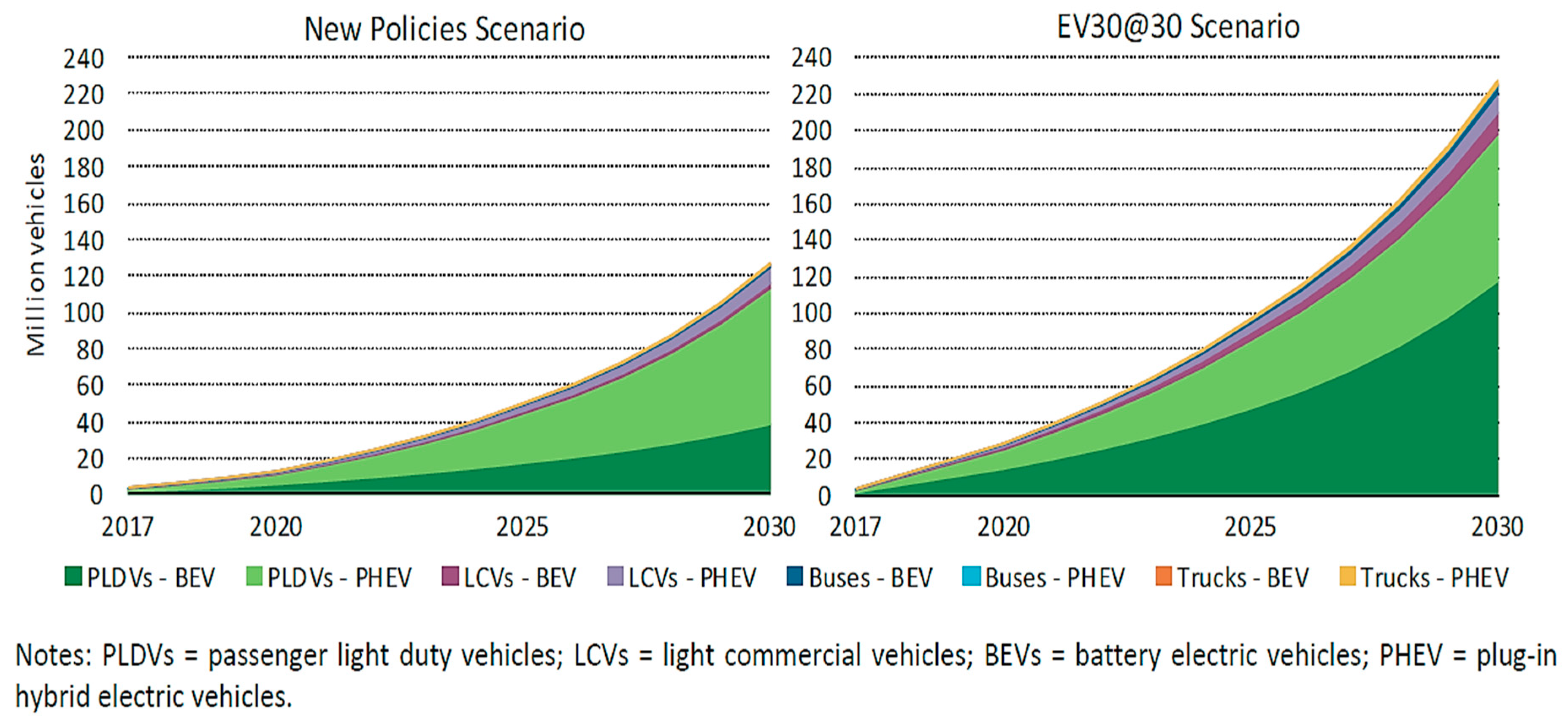
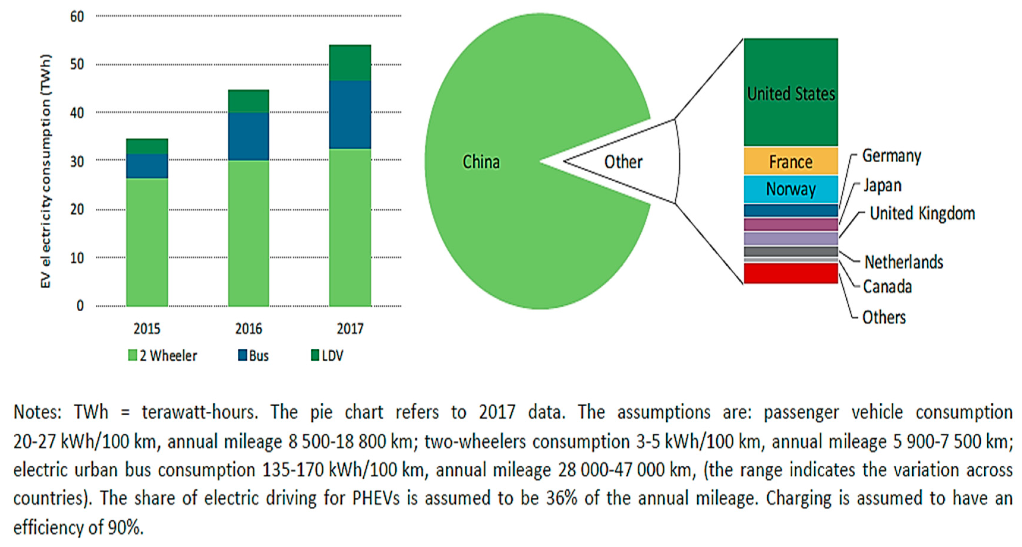
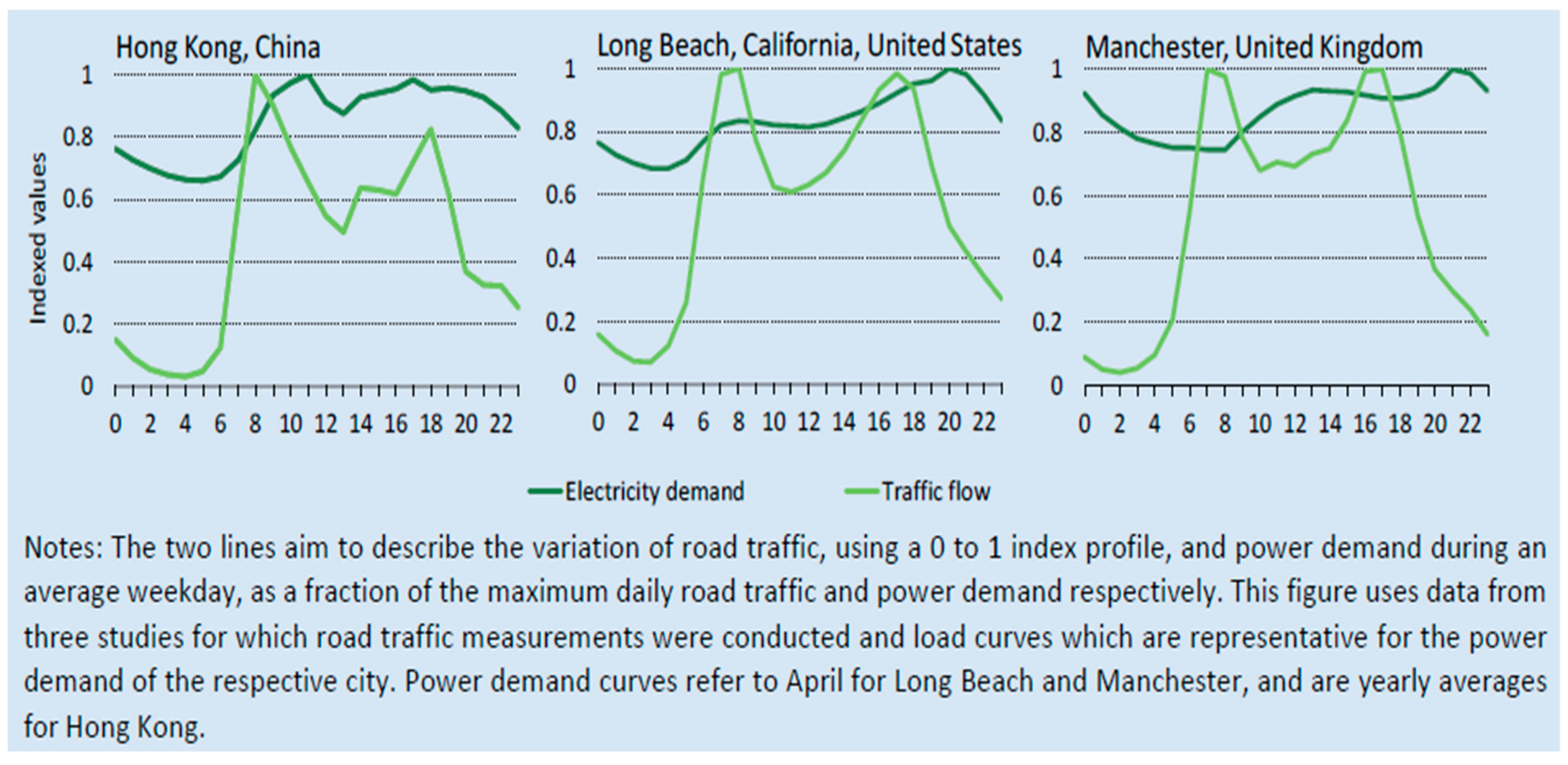
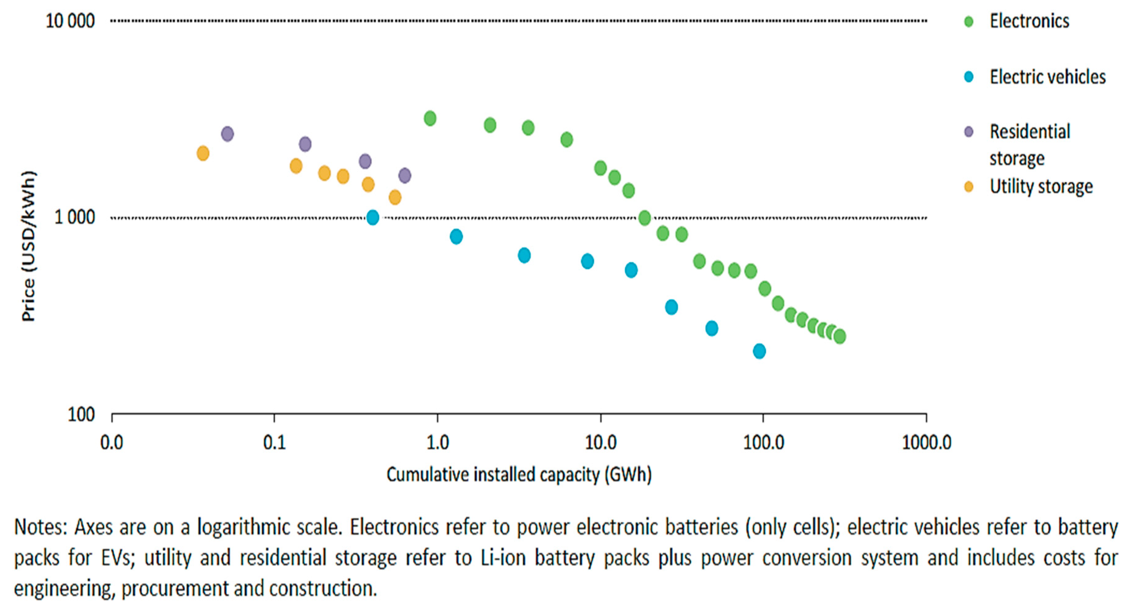
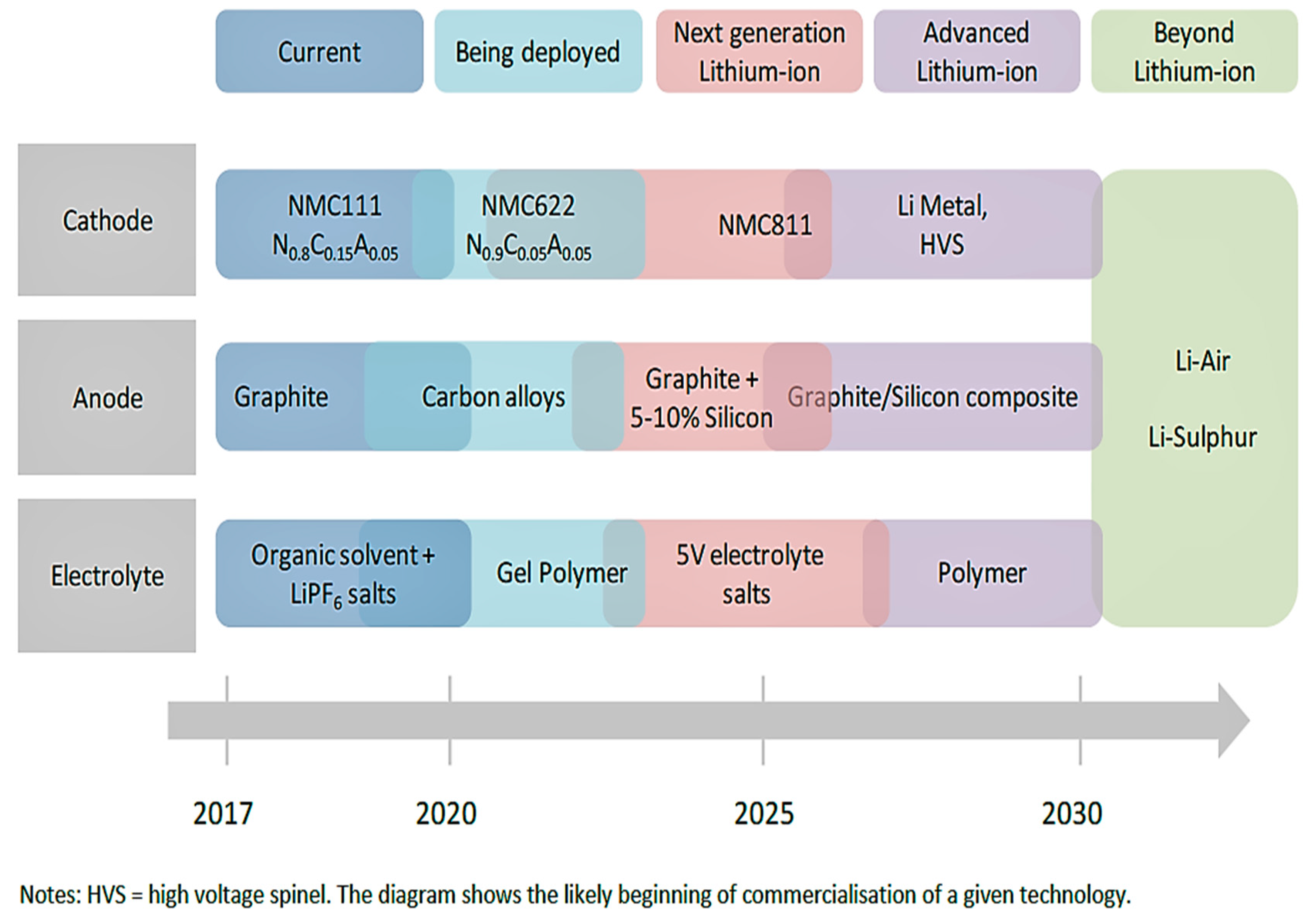
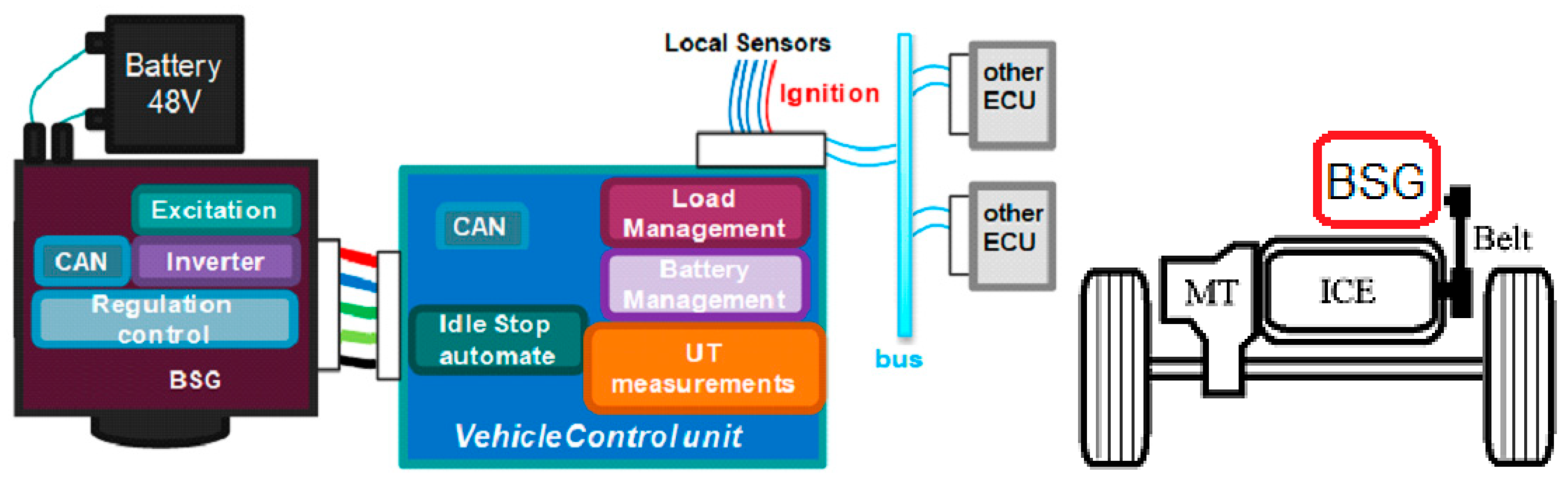
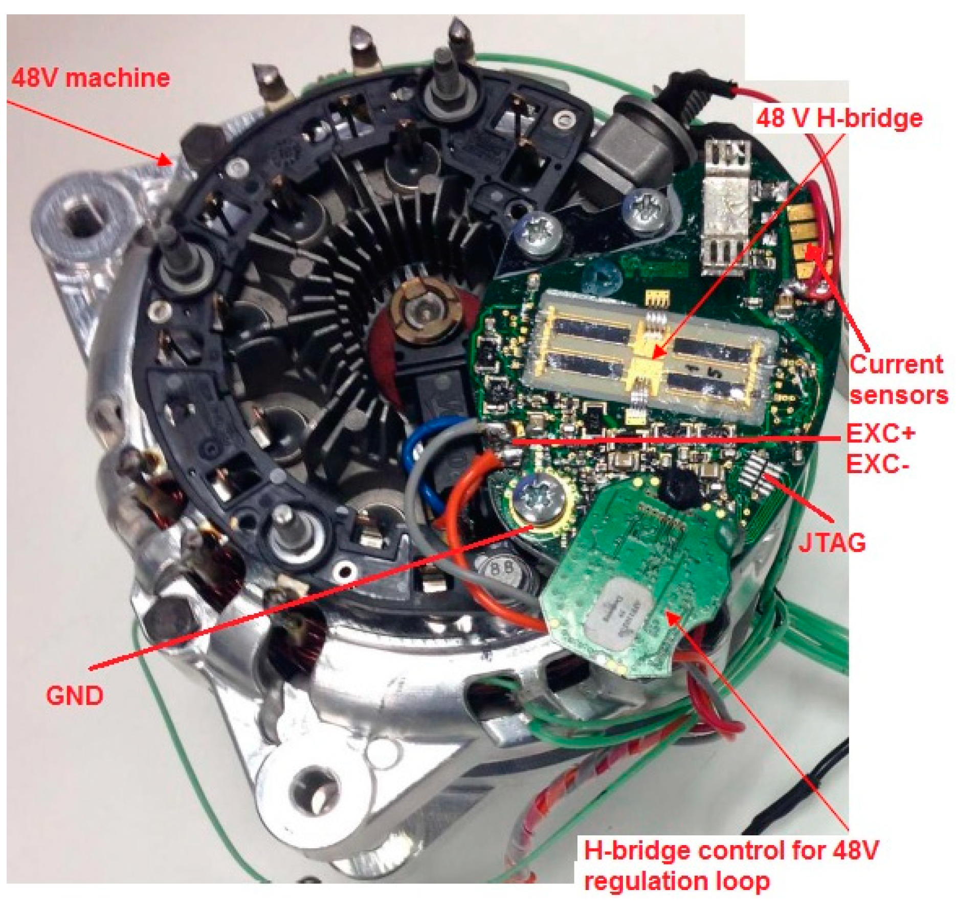
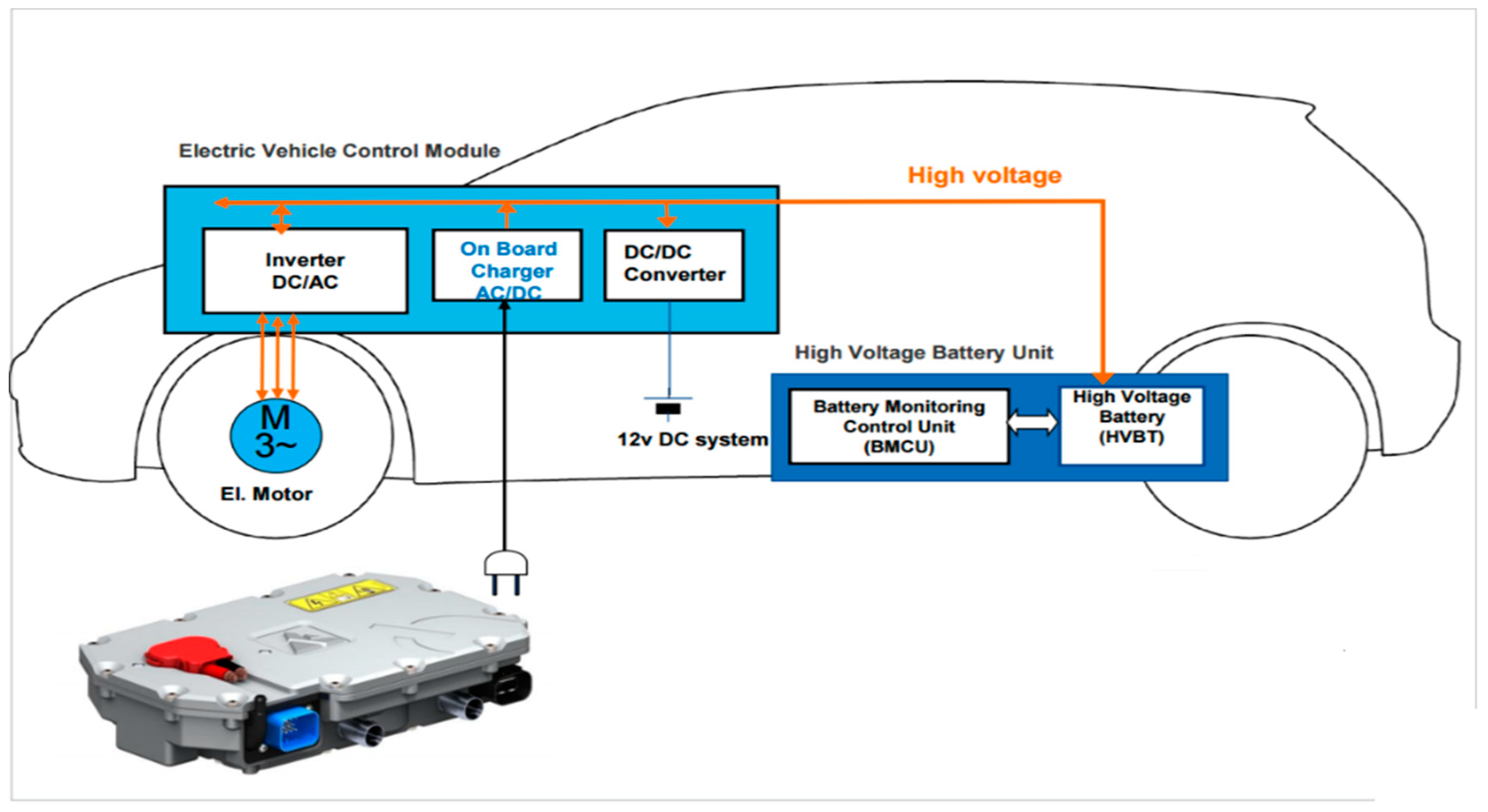
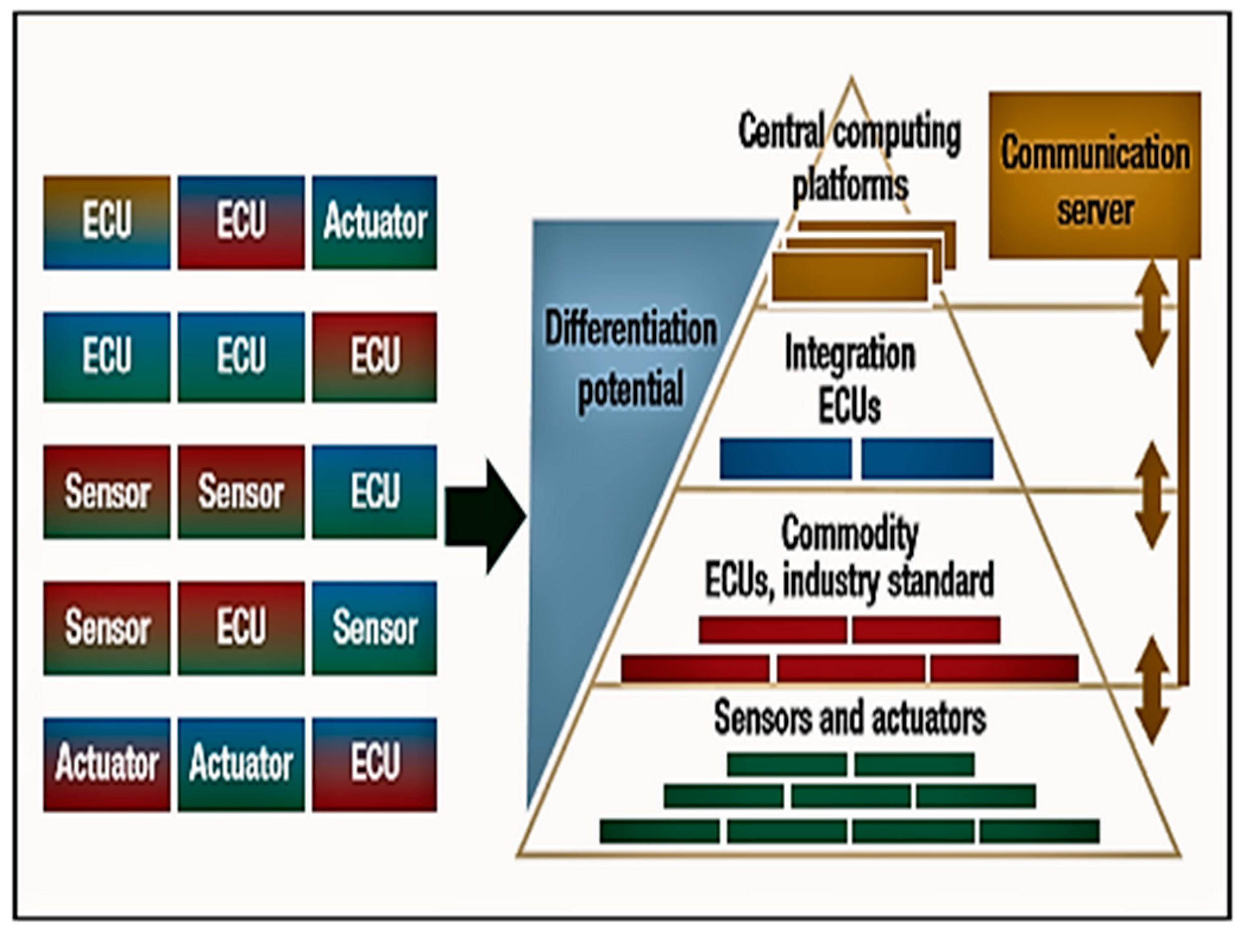
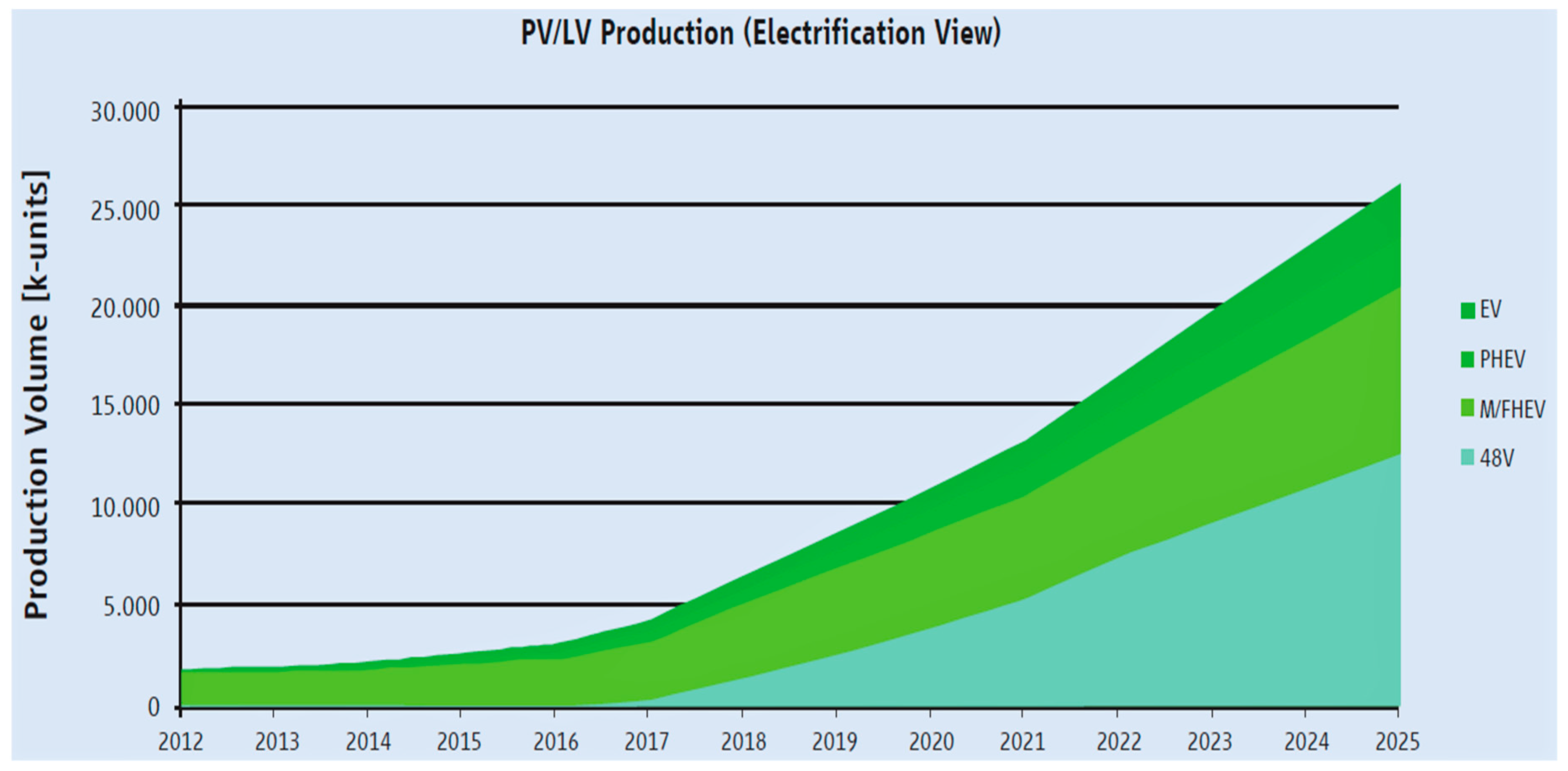
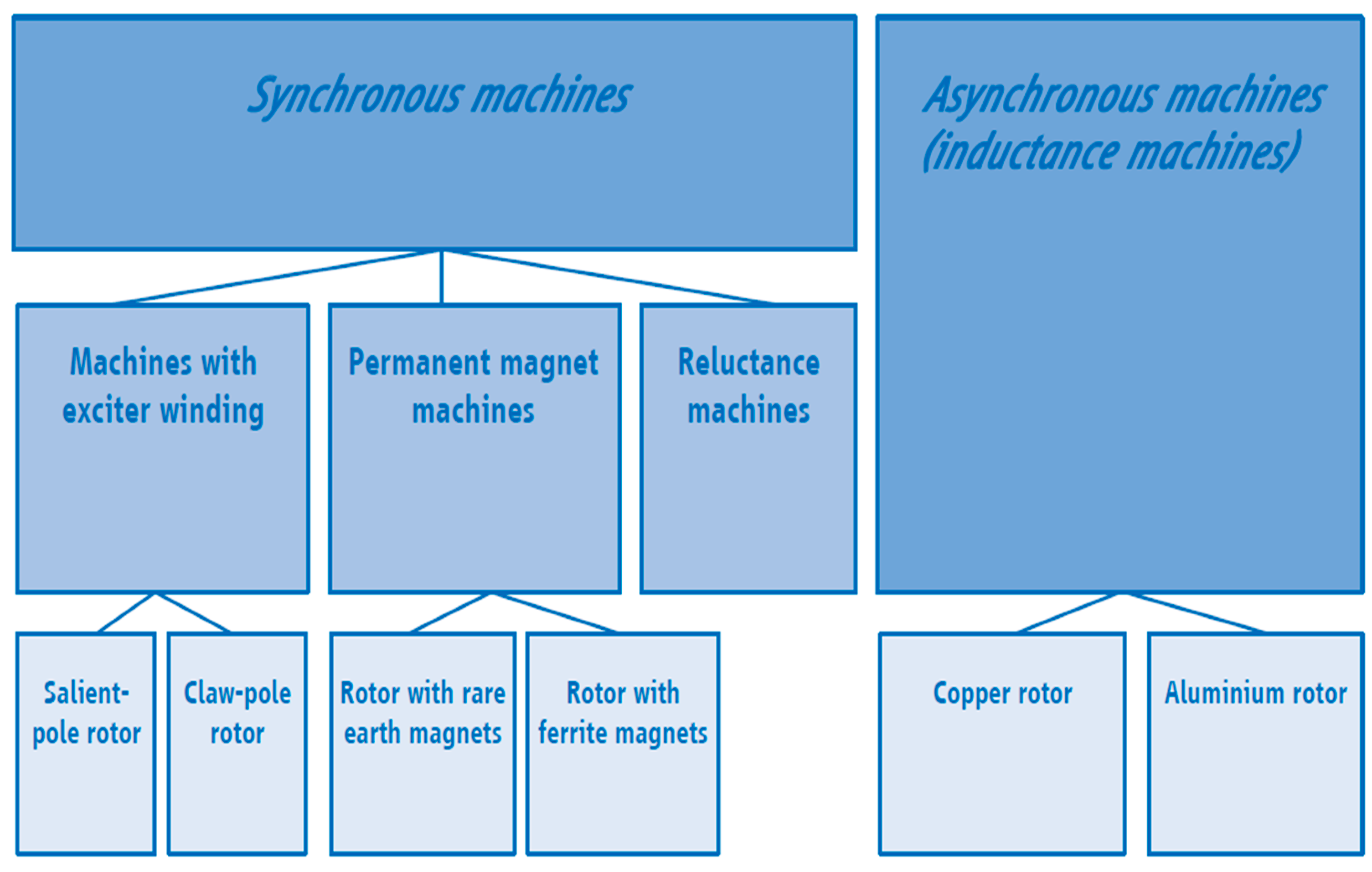
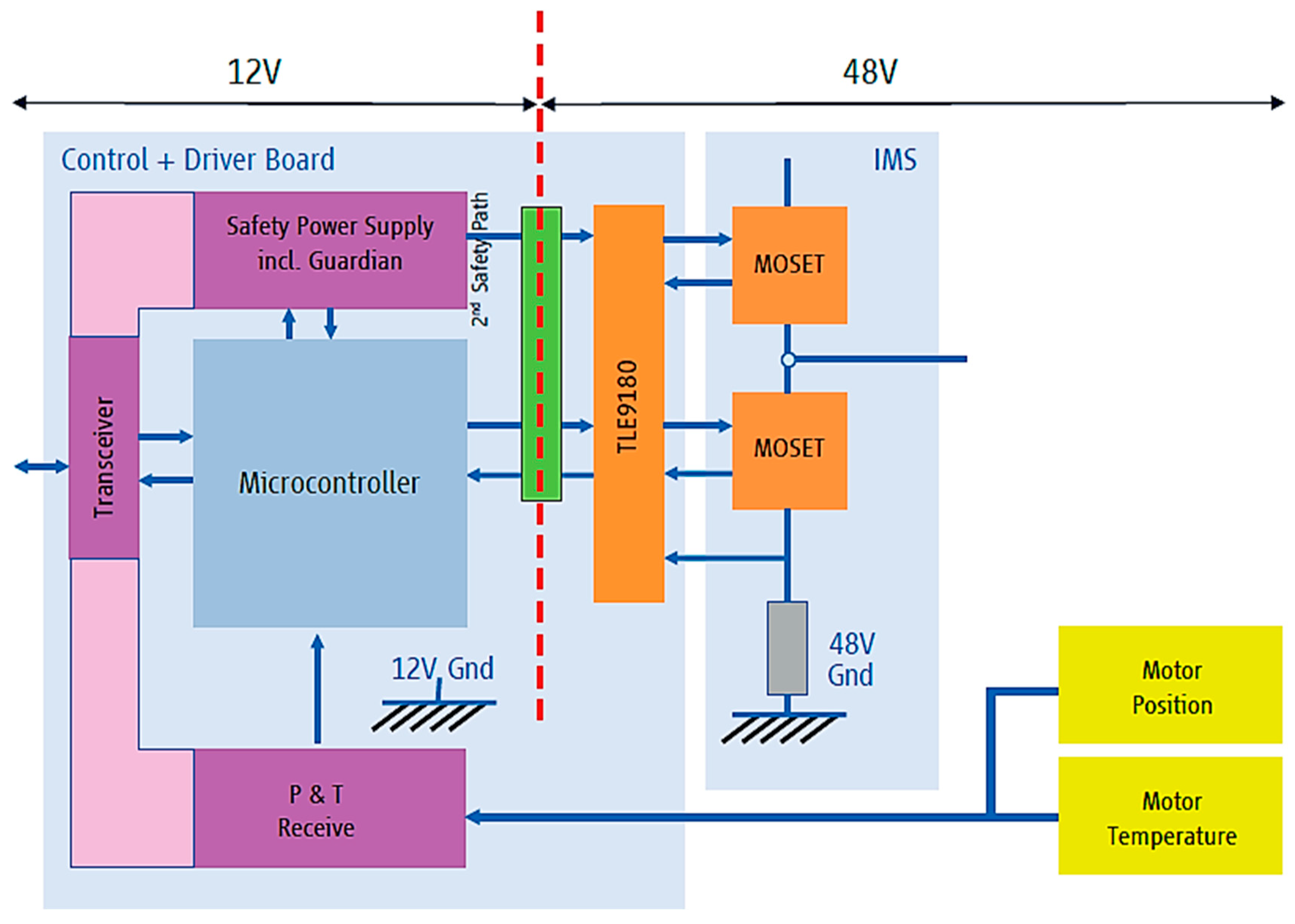
Table 1.
48 V H-bridge vs. state-of-art, rotor current control.
| Max. Current | Voltage | ON-Resistance (High/Low-Side) | |
|---|---|---|---|
| Current work | 17 A | 48 V | 11 mΩ/8 mΩ |
| [33] | 8 A | 12 V | 62 mΩ/47 mΩ |
© 2018 by the authors. Licensee MDPI, Basel, Switzerland. This article is an open access article distributed under the terms and conditions of the Creative Commons Attribution (CC BY) license (http://creativecommons.org/licenses/by/4.0/).
Share and Cite
MDPI and ACS Style
Mihet-Popa, L.; Saponara, S. Toward Green Vehicles Digitalization for the Next Generation of Connected and Electrified Transport Systems. Energies 2018, 11, 3124. https://doi.org/10.3390/en11113124
AMA Style
Mihet-Popa L, Saponara S. Toward Green Vehicles Digitalization for the Next Generation of Connected and Electrified Transport Systems. Energies. 2018; 11(11):3124. https://doi.org/10.3390/en11113124
Chicago/Turabian StyleMihet-Popa, Lucian, and Sergio Saponara. 2018. "Toward Green Vehicles Digitalization for the Next Generation of Connected and Electrified Transport Systems" Energies 11, no. 11: 3124. https://doi.org/10.3390/en11113124
Note that from the first issue of 2016, this journal uses article numbers instead of page numbers. See further details here.