Article

Hybrid PV-Wind, Micro-Grid Development Using Quasi-Z-Source Inverter Modeling and Control—Experimental Investigation

by
Neeraj Priyadarshi
1,
Sanjeevikumar Padmanaban
2,
Dan M. Ionel
3,
Lucian Mihet-Popa
4,* and
Farooque Azam
1
1
Department of Electrical Engineering, Millia Institute of Technology, Purnea 854301, India
2
Department of Energy Technology, Aalborg University, 6700 Esbjerg, Denmark
3
Power and Energy Institute Kentucky (PEIK), Department of Electrical and Computer Engineering, University of Kentucky, 689 FPAT, Lexington, KY 40506-0046, USA
4
Faculty of Engineering, Østfold University College, Kobberslagerstredet 5, 1671 Kråkeroy-Fredrikstad, Norway
*
Author to whom correspondence should be addressed.
Energies 2018, 11(9), 2277; https://doi.org/10.3390/en11092277
Submission received: 2 June 2018 / Revised: 16 August 2018 / Accepted: 21 August 2018 / Published: 29 August 2018

Abstract

:
This research work deals with the modeling and control of a hybrid photovoltaic (PV)-Wind micro-grid using Quasi Z-source inverter (QZsi). This inverter has major benefits as it provides better buck/boost characteristics, can regulate the phase angle output, has less harmonic contents, does not require the filter and has high power performance characteristics over the conventional inverter. A single ended primary inductance converter (SEPIC) module used as DC-DC switched power apparatus is employed for maximum power point tracking (MPPT) functions which provide high voltage gain throughout the process. Moreover, a modified power ratio variable step (MPRVS) based perturb & observe (P&O) method has been proposed, as part of the PV MPPT action, which forces the operating point close to the maximum power point (MPP). The proposed controller effectively correlates with the hybrid PV, Wind and battery system and provides integration of distributed generation (DG) with loads under varying operating conditions. The proposed standalone micro grid system is applicable specifically in rural places. The dSPACE real-time hardware platform has been employed to test the proposed micro grid system under varying wind speed, solar irradiation, load cutting and removing conditions etc. The experimental results based on a real-time digital platform, under dynamic conditions, justify the performance of a hybrid PV-Wind micro-grid with Quasi Z-Source inverter topology.

1. Introduction

Micro-grid comprises the combination of interconnected loads and distributed energy resources (DER), including energy storage devices and several active loads/prosumers which work as a controlled unit to deliver the electric demand for miniature location. It supplies power generation with tremendous reliability as well as an affirmation to varying loads [1,2,3]. Fossil fuels and nuclear sources are treated as the traditional energy sources, which provide electricity and are not located closer to the load point. As the conventional energy sources are not environmentally friendly and due to the long-distance transmission, there are considerable power losses that can occur. Therefore, nowadays, renewable energy sources have been given more attention by the researchers and industry to generating alternative power [4,5,6,7,8,9,10,11,12]. Distributed generating (DG) source such as solar, wind, fuel cell, hydro, tidal, etc. are considered as the main renewable technology, which is highly flexible, expandable and has environmentally friendly behavior. The maximum power point tracking (MPPT) is the important constituent needed to achieve the maximum power point (MPP) as an operating point which enables the utmost power extraction for renewable sources [13,14]. Several MPPT techniques, including Perturb & Observe (P&O), Incremental Conductance (INC), Fuzzy logic control (FLC), Artificial Neural Network (ANN), Particle swarm optimization (PSO), Ant Colony Optimization (ACO), Artificial Bee Colony (ABC), Firefly Algorithm (FA) etc. reviewed in the literature were unable to detect global peak point with partial shade situations [15,16,17,18,19,20,21,22,23,24,25,26,27].In this work, Modified Power Ratio Variable Step (MPRVS) based on the P&O technique is proposed without the proportional-integral(PI) controller utilization, which reduces power oscillation near to MPP in comparison to a conventional P&O algorithm and also provides the prevention to battery charging from voltage fluctuation.
To avoid multi reversal generation occurrence in a micro-grid system, in the current research, a Quasi Z-Source inverter is employed [28,29,30,31,32,33]. The DC-DC converter is a vital interface to achieve a peak power generation from PV modules. In this work, a high-quality tracking behavior is achieved by employing single ended primary inductance converter (SEPIC), which provides high voltage gain with better buck/boost performance compared to other dc-dc switched power converters [34]. In this paper, an additional dc-dc converter (SEPIC converter) is used because it comprises buck/boost capabilities. Moreover, QZsi combines a boost converter and an inverter. The MPRVS based P&O MPPT is controlled through the SEPIC converter which provides MPP achievement and works effectively under varying sun insolation and wind velocity. Moreover, the SEPIC converter works as an impedance adapter between the PV panel and Z-source inverter. Jain et al. [35] have implemented QZsi based grid PV system using a predictive controller in which the active and reactive power have been regulated. However, this work is discussed only for the PV system which utilized the traditional INC MPPT with a classical PI controller as a dc bus regulator. Liu et al. [36] have discussed QZsi based multilevel inverter for grid PV power system, which provides precise MPPT and dc-link voltage regulation at the unity power coefficient. However, during practical justification, voltage/current sensors and bulk resistor models are required, which has a high cost. Nevertheless, this work only explains the performance of QZsi based multilevel inverter for only the PV systems rather than the hybrid system. Amini et al. [37] have discussed the cloud computing applications in micro grid clusters. A real time digital simulator is employed for the physical interpretation of power routing which can be utilized for electrical grid utility with the communication system. However, the application of the proposed scheme with hybrid PV-Wind micro grid systems is missing in this research work. Ali et al. [38] have conferred game theory structure for improvement of smart grid efficiency in which the Femtocell communication system is employed. However, the main disadvantage of this proposed communication system is interference in cross layer. Furthermore, the proposed game theory application with hybrid PV-Wind micro grid system has not been discussed in this research work. Vignesyn et al. [39] have discussed the hybrid micro grid for standalone/Grid mode operation with Z-source inverter. This paper discusses the behavior of micro grid under varying loading conditions, solar insolation and wind speed using simulation environment (MATLAB) only. The real time implementation is missing in this research work. In this research work, to reduce multiple reverse conversions and for improving the efficiency of the micro grid, hybrid PV-Wind with Quasi Z-source inverter has been implemented. Furthermore, SEPIC converter acts as a dc link interface with MPPT functioning. This research work is organized under 3 main sections. Section 1 discusses the micro-grid system with an extensive literature review of MPPT techniques, dc-dc converters with benefits of Z-source inverter. Section 2 presents the complete structure of the hybrid PV-Wind micro-grid system. It explains the PV generator modeling, wind turbine model, MPRVS based MPPT algorithm, design specifications of SEPIC converter, battery model as well as the modes of operations of the Quasi Z-source inverter. Section 3 presents the experimental results which validate the performance of the proposed hybrid PV-wind micro-grid system. The novelty of this research paper is MPRVS based advanced MPPT algorithm have neither been dis-coursed nor been utilized before for the hybrid PV-wind micro-grid with Quasi Z-source inverter experimentally.

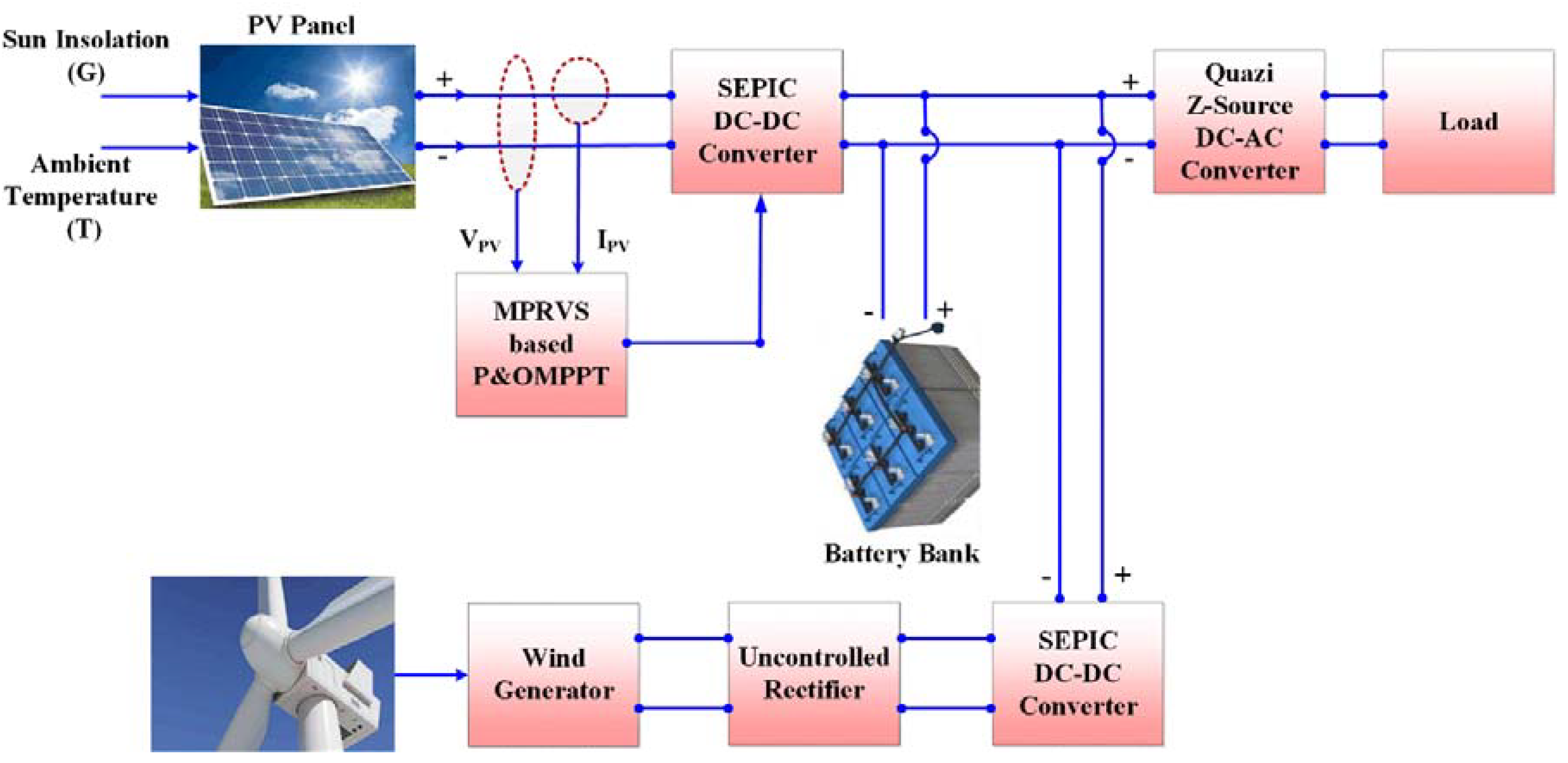
2. Hybrid PV-Wind Micro Grid Structure

The proposed structure of the PV-Wind micro grid system is shown in Figure 1. The micro grid system contains a PV generator, a Wind Turbine, a battery system and the power electronic converter topologies. To analyze the proposed system, the equivalent circuit with two diode models for the PV generator has been used because of its better power extraction capability when compared with the single diode model. The rotor of the wind turbine is mechanically tied to a generator to produce electrical power. A wind turbine is a complex system, but a reasonably simple representation is possible by modeling the aerodynamic torque or power based on turbine characteristics (non-dimensional curves of the power coefficient). A battery solution is also necessary to balance the stochastic fluctuations of photovoltaic (PV) power and wind power injected to the grid/load. In this section, a short description about how these main components of the proposed micro grid system have been modeled are presented.

2.1. PVG Mathematical Model

Figure 2 illustrates the basic PV cell schematic diagram, which is responsible for the transformation of the solar energy into electric power using photoelectric effect which comprises numerous cells. In this paper, the two-diode model is considered to deliver better accuracy compared to the single diode model.
The PV cell output current is expressed mathematically as:
I N = I P h o t o n I D i o d e 1 I D i o d e 2 ( V N + I N R S E R P a r a l l e l )
Also, Photon current is evaluated mathematically as:
I P h o t o n = [ I P h o t o n _ S T C + K S ( T C T S T C ) ] × G G S T C
Diode saturation current can be expressed as:
I D i o d e 1 = I D i o d e 2 = I S h o r t _ S T C + K S ( T C T S T C ) e x p [ ( V o p e n _ S T C + K V L ( T C T S T C ) ) ] V T h e r m a l 1

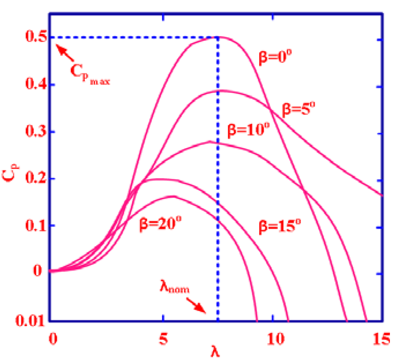
2.2. Wind Turbine Modeling

A wind turbine is essentially a machine that converts the kinetic energy first into mechanical energy at the turbine shaft, and then into electrical energy. The wind turbine power generation depends mainly on wind velocity in which the rotors are mechanically linked to a generator. A simple model can be achieved by using the power coefficient (CPR) as a function of tip speed ration and the blade pitch angle. CPR (Performance/power coefficient) Vs tip speed (λT.S) curve is plotted for different βP.B (Pitch blade angle) in Figure 3.
Generated mechanical power output from the wind turbine can be written using Equation (4) which is depending on wind velocity (VWind), RT (Turbine radius) and CPR (Performance coefficient) as:
P M e c h a n i c a l = 1 2 C P R π R T 2 ρ a . d V W i n d 3
Also, the ratio of tip speed (λT.S) can be described mathematically which is correlated with an angular velocity of the blade (ωA.V), VWind and RT as:
λ T . S = ω A . V × R T V W i n d
And coefficient of performance is expressed with λT.S and βP.B (Pitch blade angle) as:
C P R ( λ T . S , β P . B ) = 0.72 [ 150 λ j 2 × 10 3 β P . B 131 × 10 1 ] e 185 × 10 1 λ j
where,
1 λ j = 1 ( λ T . S + 8 × 10 2 β P . B ) 35 × 10 3 1 + β P . B 3
λ T . S = ω G × R T V W i n d × ƞ g e a r
ƞ g e a r = ω G M × R T λ T . S V W i n d

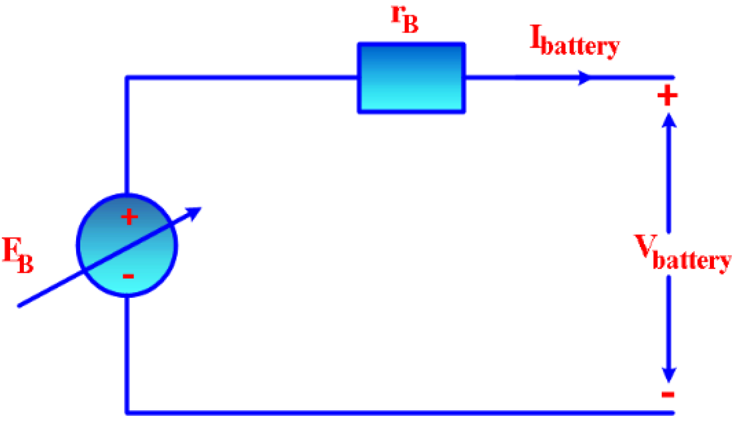
2.3. Electric Equivalent Circuit of the Battery Model

A battery is a vital component for a hybrid system which provides the solution under fluctuating action of renewable energy sources. In this work, the electric circuit-based battery model is employed, which provides better dynamics for a state of charge operation mode. It comprises a voltage source (ideal) with a series of internal resistance which evaluates the battery behavior as depicted in Figure 4.
Final voltage controlled is obtained mathematically as:
V = E B V P O × Q B a t Q B a t I B a t t e y d t + A e x p . e ( B e x p I B a t t e r y d t )

3. Power Electronic Converters used to Control the Proposed Micro Grid System. Description and Mathematical Modelling

The power converters have been developed to manage the maximum energy harvesting and power processing for the hybrid solution with Photovoltaic (PV) and wind power generators. The topologies involved in this study contains two topologies of power electronic converters: a SEPIC converter and a Quasi Z-Source Inverter (QZsi). The MPPT method for QZsi is introduced based on the P&O method to minimize the voltage stress on the inverter. Moreover, it prevents overlapping between Shoot-Through (ST) duty ratio and modulation index using DC-Link voltage controller. The output current is regulated using the stationary frame current controller, achieving lower Total Harmonic Distortion (THD) as much as possible. The SEPIC based soft switching for MPPT action is controlled through an advanced MPRVS based P&O MPPT. A quasi Z-source inverter with the common grounding characteristics is employed to get high voltage gain. Employed inverter operates in two modes of operation as the shoot through and the non-shoot through the states.

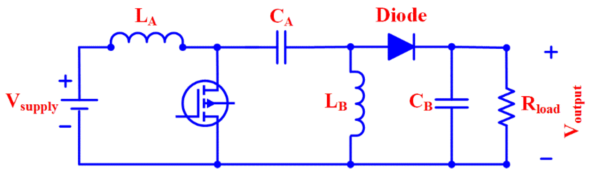
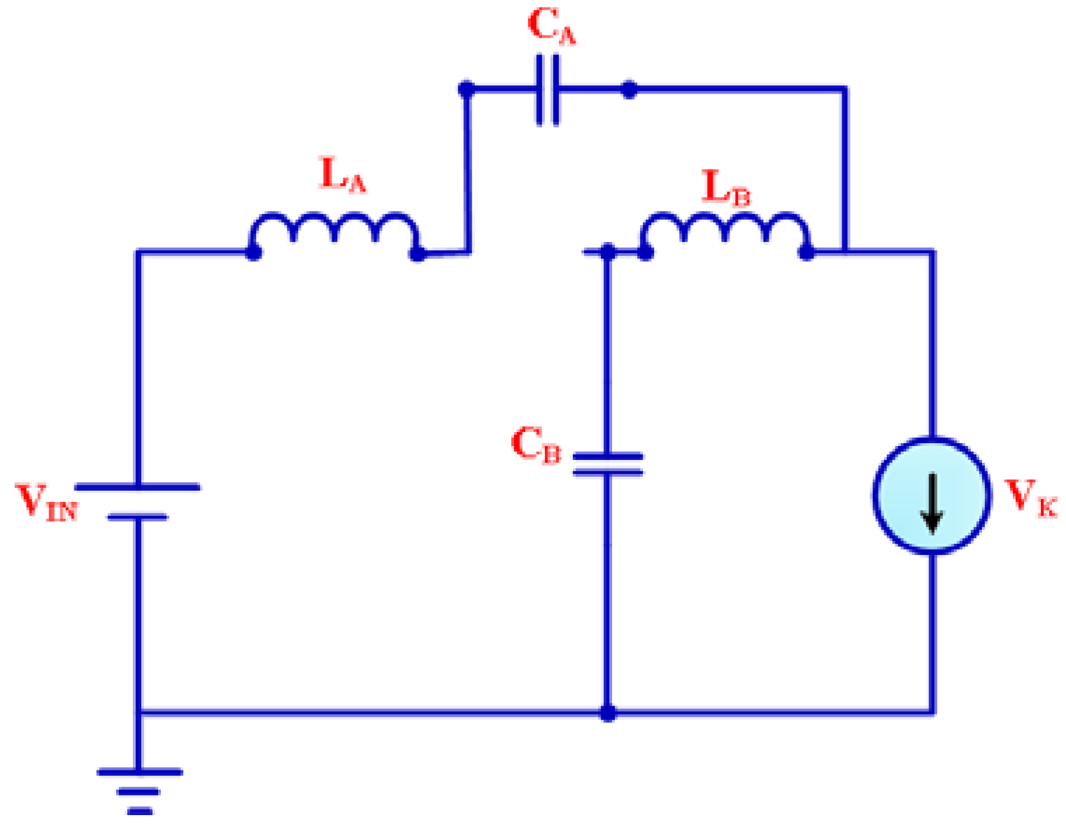
3.1. SEPIC Converter Model

Single ended primary inductor converter (SEPIC) is considered as an impedance adapter between the PV module and the Z-source inverter as it provides high gain throughout the operation, better voltage performance and high voltage rating for lower/higher power requirements. When boost converter combines with the additional inductor and the capacitor, a SEPIC converter is developed. In contrast with the buck boost converter, the polarity of SEPIC is kept positively as it is depicted in Figure 5. Table 1 portrays the employed SEPIC converter parameters during an implementation.
V o u t p u t = V s u p p l y × D d u t y 1 D d u t y
L A = V s u p p l y × D d u t y I L A × f s w i t c h i n g
L B = V s u p p l y × D d u t y I L B × f s w i t c h i n g
C A = V o u t p u t × D d u t y R L o a d × V o × f s w i t c h i n g
C B = V o u t p u t × D d u t y R L o a d × V o × f s w i t c h i n g

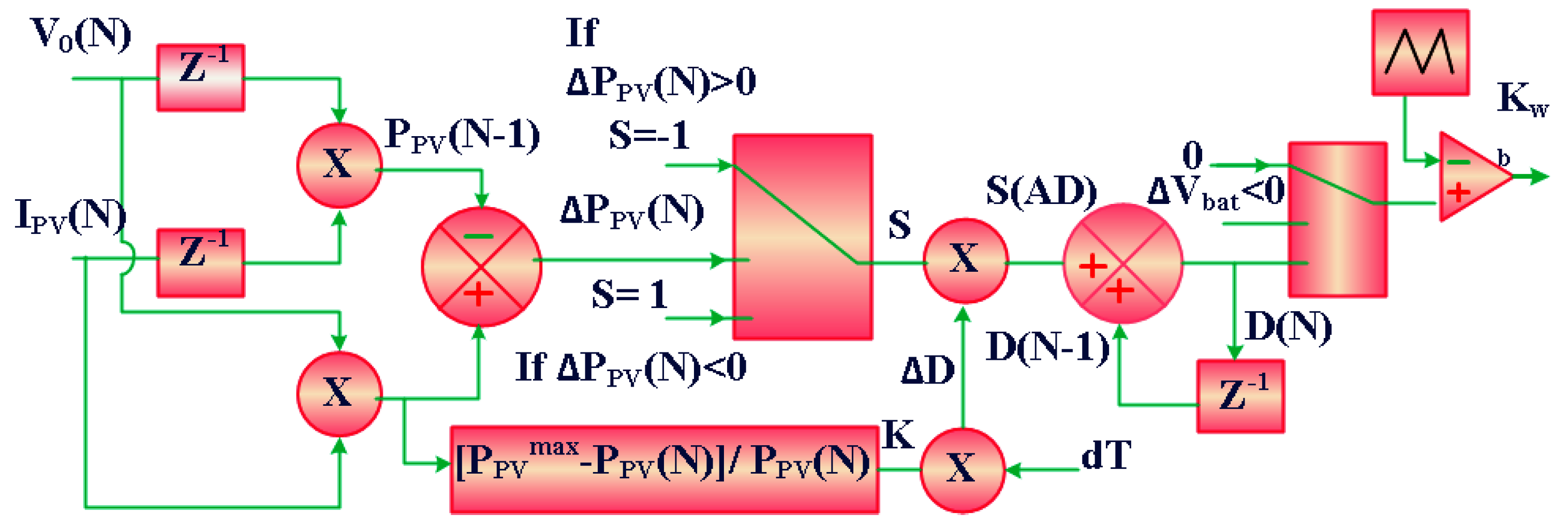
3.2. Modified Power Ratio Variable Step Based P&O MPPT

Figure 6 demonstrates the working model of MPRVS based P&O technique for optimal PV power extraction from solar modules. The generation of gating pulses to the SEPIC converter is possible without the action of the PI controller, which makes the reduction of power oscillation nearer to MPP and forces operating point close to the MPP. It also prevents the battery charging system from over voltage. The instantaneous power obtained through PVG [ P P V ( N ) ] at SEPIC output terminal is calculated as:
P P V ( N ) = V 0 ( N ) × I P V ( N )
Also, the previous instantaneous power is mathematically described as:
P P V ( N 1 ) = V P V ( N 1 ) × I P V ( N 1 )
And if
P P V ( N ) = P P V ( N ) P P V ( N 1 ) > 0 ,   S = 1
& P P V ( N ) P P V ( N 1 ) < 0 ,   S = + 1
Again,
D ( N ) = D ( N 1 ) + S × D
D = Step perturbation of duty ratio = K × d T
dT = Fixed step size
K = Variable power ratio
K = P P V m a x P P V ( N ) P P V ( N )

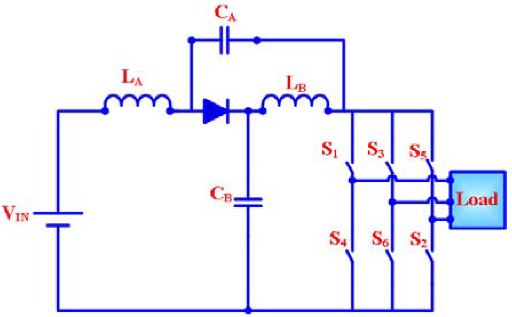
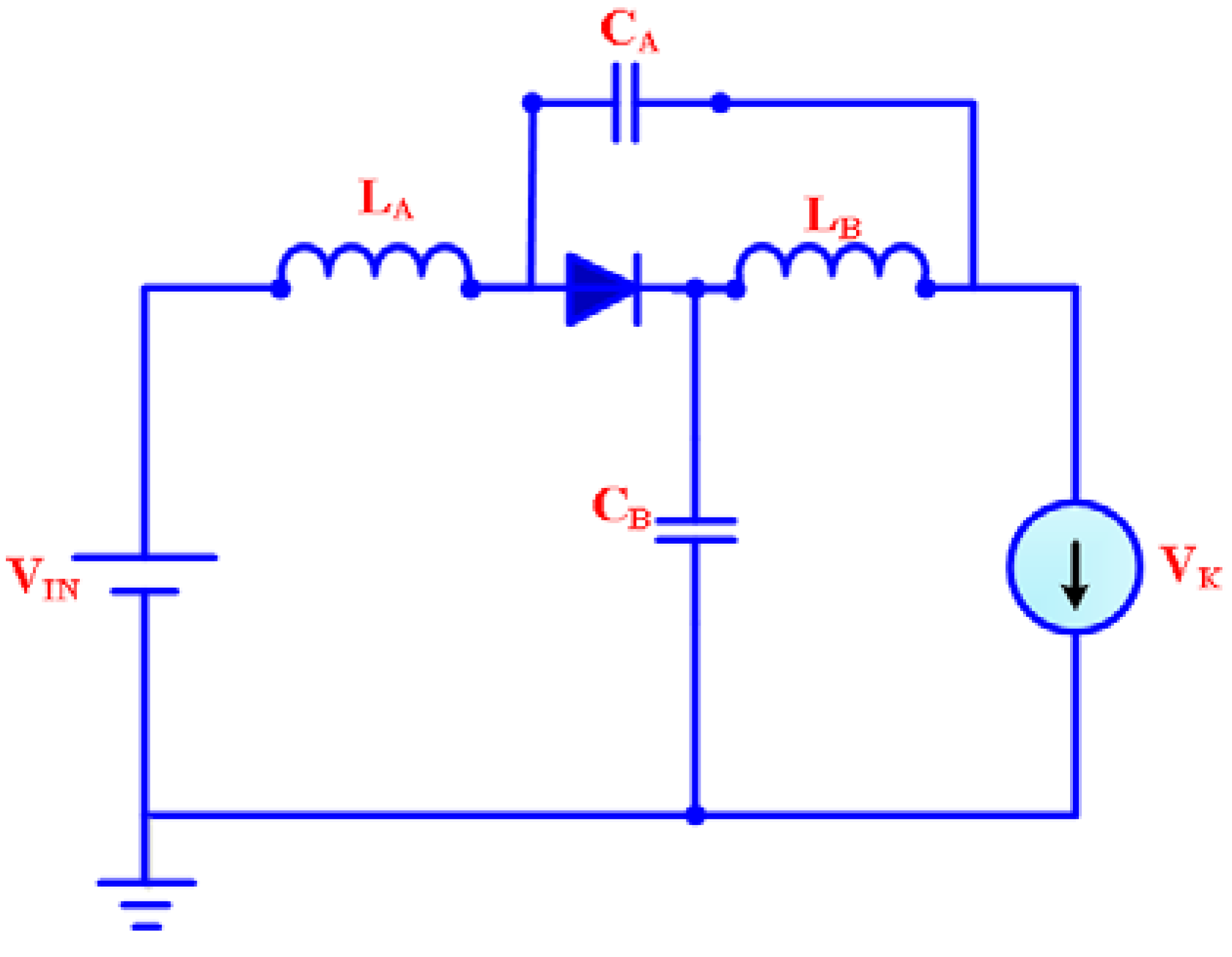
3.3. Quasi Z-Source Inverter Mathematical Modeling

Figure 7 presents the equivalent power circuit of Quasi Z-source inverter which comprises of LA, LB, CA, CB components with impedance circuit. The considered Z-Source Quasi inverter has no filter requirement, better buck/boost characteristics, able to regulate the phase angle output, less size, continuous conducting mode working, less harmonic content, high efficiency and with better power performance over the conventional inverter as major advantages. The Quasi Z-source inverter operates in two modes of operation. In the non-shoot mode, the equivalent circuit has 6 active states with 2 zero states. The TS is the total switched inverter with TA and TB as the shoot through the state and the non-shoot through state, respectively. The duty ratio Dduty of SEPIC converter is mathematically written as:
D d u t y = T A T S
Mode I: The equivalent model of Quasi Z-source inverter is depicted in Figure 8 and mathematical equations governing non-shoot through the state is expressed as:
V L A = V I N V C A
V L B = V C B
V D I O D E = 0
Mode II: Figure 9 illustrates the equivalent model of Quasi Z-source inverter in shoot through the state mode with the mathematical expression as:
V L A = V I N + V C A
V L B = V C B
V D I O D E = V C A + V C B
Under the steady condition, the average inductor voltage becomes zero.
V L A = [ ( V I N + V C B ) T A + ( V I N V C A ) T B T S ] = 0
V L B = [ V C A T A + ( V C B ) T B T S ] = 0
On solving the above equations, capacitor voltage ( V C A & V C B ) is calculated mathematically as:
V C A = ( T B T B T A ) × V I N
V C B = ( T A T B T A ) × V I N
Maximum voltage across DC-link = V C A + V C B
Putting Equations (26) and (27) in (28) we get
Maximum DC-link voltage = | 1 1 2 T A T S | V I N = K × V I N

4. Experimental Setup Description and Results

4.1. Description of the Experimental Setup

The considered hybrid PV-Wind micro grid is tested using MPRVS based P&O MPPT with employed Z-source inverter. Figure 10 depicts the developed practical structure of the proposed hybrid micro grid based on a real-time platform, dSPACE. The SEPIC converter is controlled through the MPRVS based P&O based MPPT, in which LV-25P and LA-25P, current and voltage sensors are employed for measuring the PV panel parameters, VPV and IPV respectively. The power factor coefficient and THD are evaluated using the power quality analyzer (FLUKE 43B), considering the main components of the converter: IGBT (IRG4PH50U), diode (Freewheel RHRG30120), driver circuit (HCPL 3120) etc. permanent magnet synchronous generator (PMSG) based wind emulator system is employed as the wind turbine generator and is mechanically coupled with the DC-motor. The switched mode power converter makes the wind turbine to have varying wind speed which produces the required mechanical torque by controlling wind turbine characteristics.

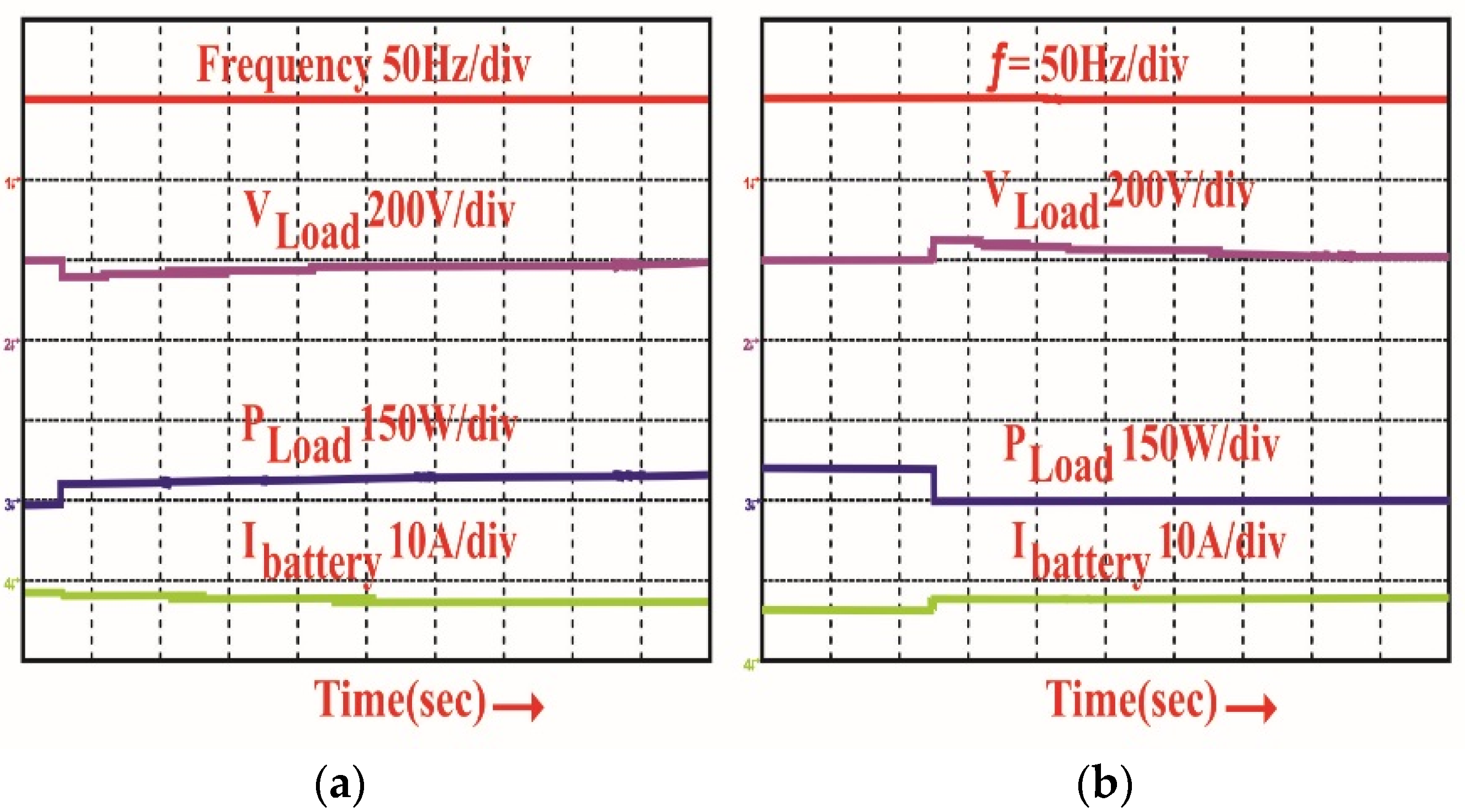
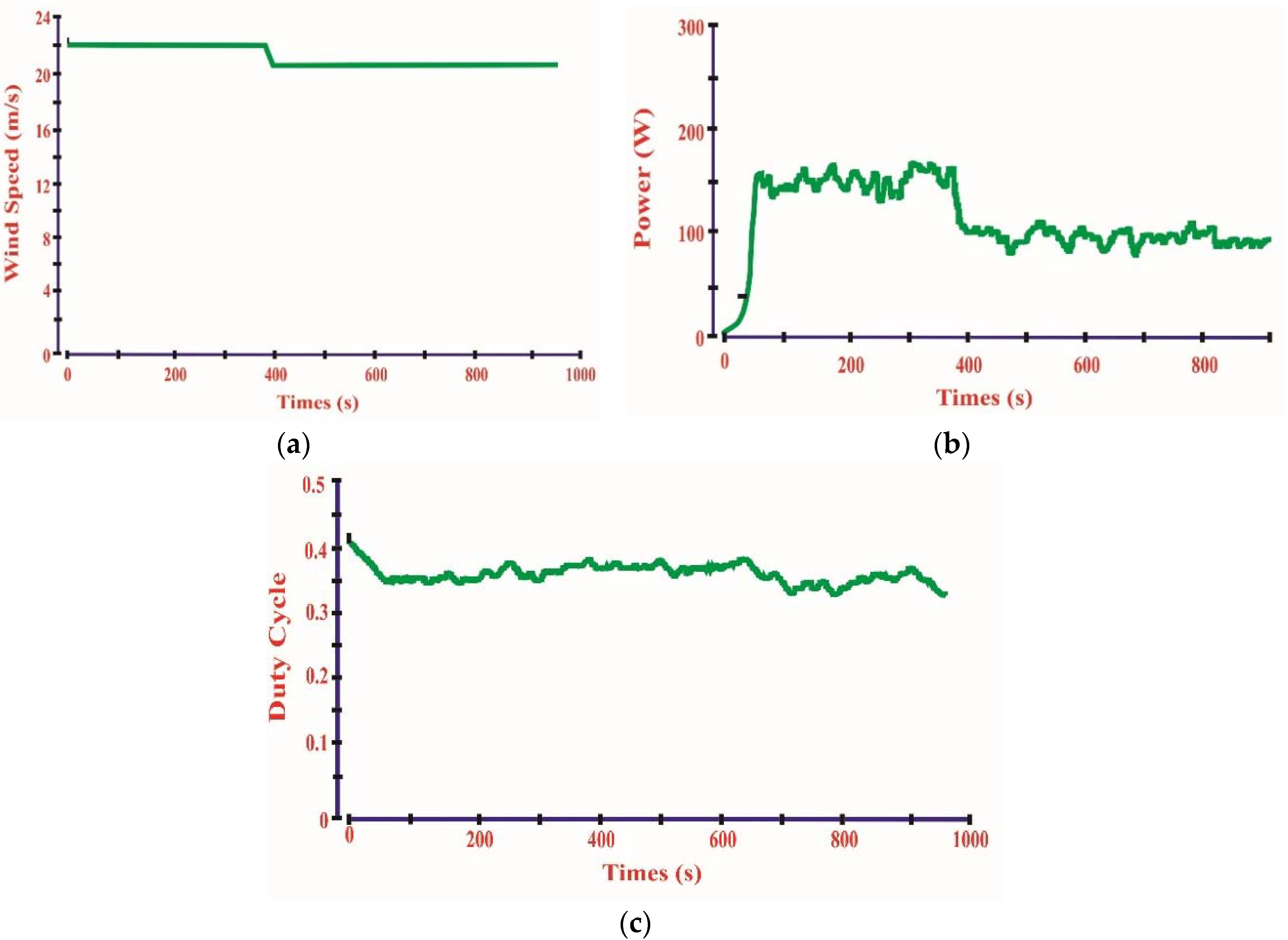
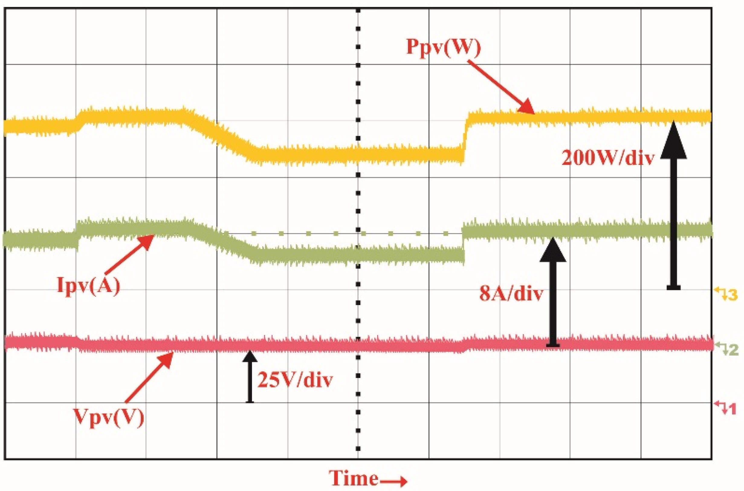
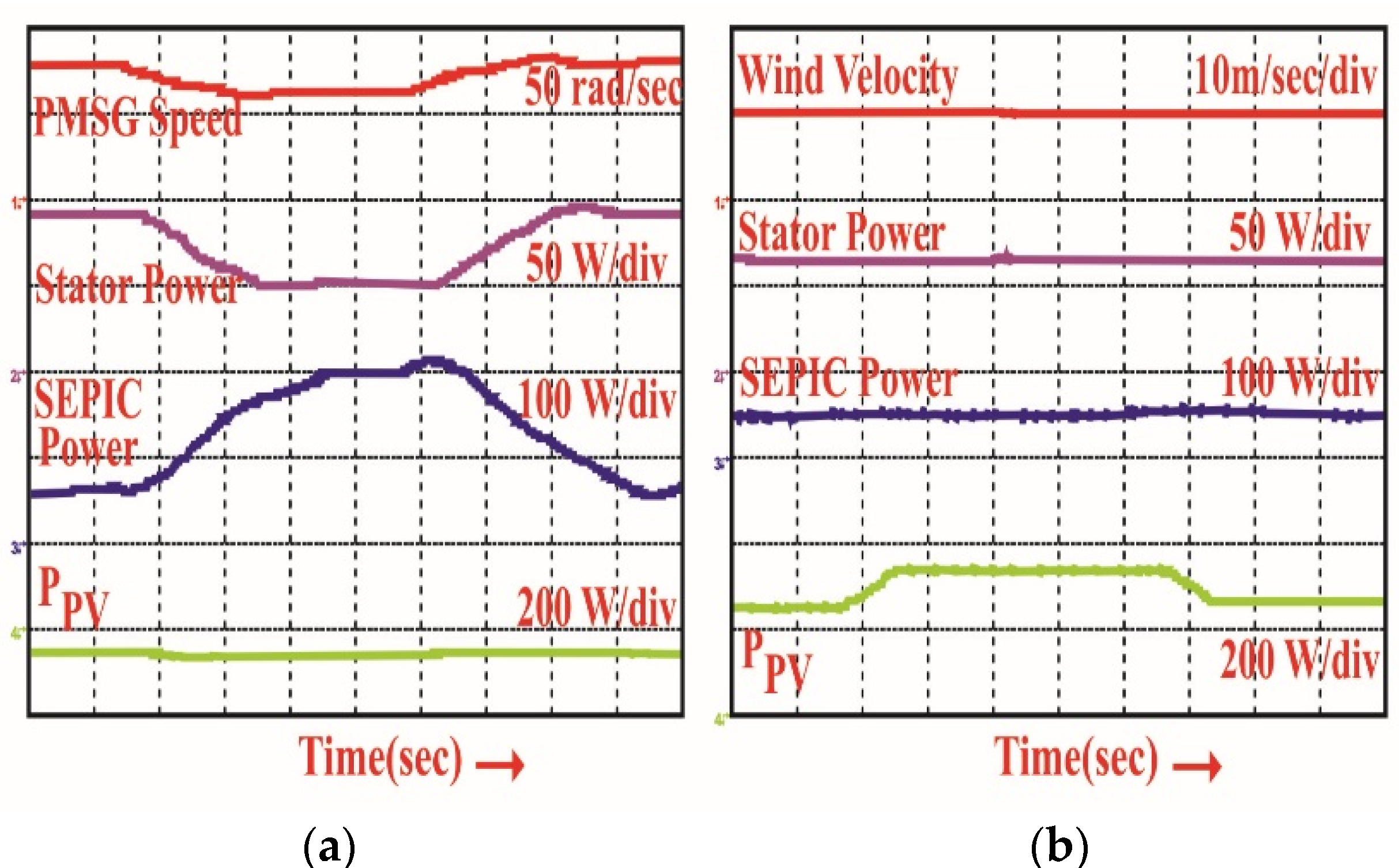
4.2. Experimental Results and Scenarious Development

The accuracy of the proposed MPRVS based P&O MPPT has been tested with changing wind operating condition depicted in Figure 11a. The employed controller works in MPP area and provides optimal tracking of wind power under the sudden changes of wind velocity shown in Figure 11b.The corresponding duty ratio of SEPIC converter is shown in Figure 11c. Furthermore, the capability of proposed MPPT tracker is examined under the first scenarios with step varying solar irradiation. Figure 12 demonstrates that the PV array has obtained parameters under the step-changes in solar irradiation and the propped system has proved high accuracy and effective PV tracking in MPP region. The obtained experimental results in Figure 13a illustrate that the performance of the proposed hybrid micro grid under the second scenarios by varying wind velocity and constant solar irradiation. Also, Figure 13b demonstrates the behavior responses of the hybrid micro grid under varying solar irradiance and constant wind velocity with MPRVS based P&O MPPT employed. The performance of the hybrid micro grid is also tested under the third proposed scenarios in the absence of wind velocity and during this operation: the load is connected/disconnected to the utility grid, which is shown in Figure 14a under the load cutting condition, and in Figure 14b, under the load removing conditions. The performance of the wind generator is evaluated under disconnecting/reconnecting operating conditions to the micro grid, which are depicted in Figure 15 and Figure 16 and reveal that the accurate performance of the proposed hybrid micro grid in varying operating situations (disconnecting operating conditions to the micro grid and reconnecting operating conditions to the micro grid), respectively.

5. Conclusions

The proposed hybrid PV-Wind micro-grid system using Quasi Z-source inverter is established practically and tested with the Real-time digital simulator dSPACE (DS 1104) platform.
The point wise findings that have been included in this section are as follows:
(i)
The MPRVS based P&O MPPT performance with SEPIC converter has been validated effectively, which delivers MPP achievement with low power oscillation for the PV system.
(ii)
The performance of the Quasi Z-source inverter has been evaluated experimentally as having better buck/boost characteristics with fast dc-link voltage regulation under different operating conditions.
(iii)
The proposed QZsi topology for a hybrid PV-Wind Turbine application in a micro grid enhanced reliability, good output power quality and efficiency improvements.
(iv)
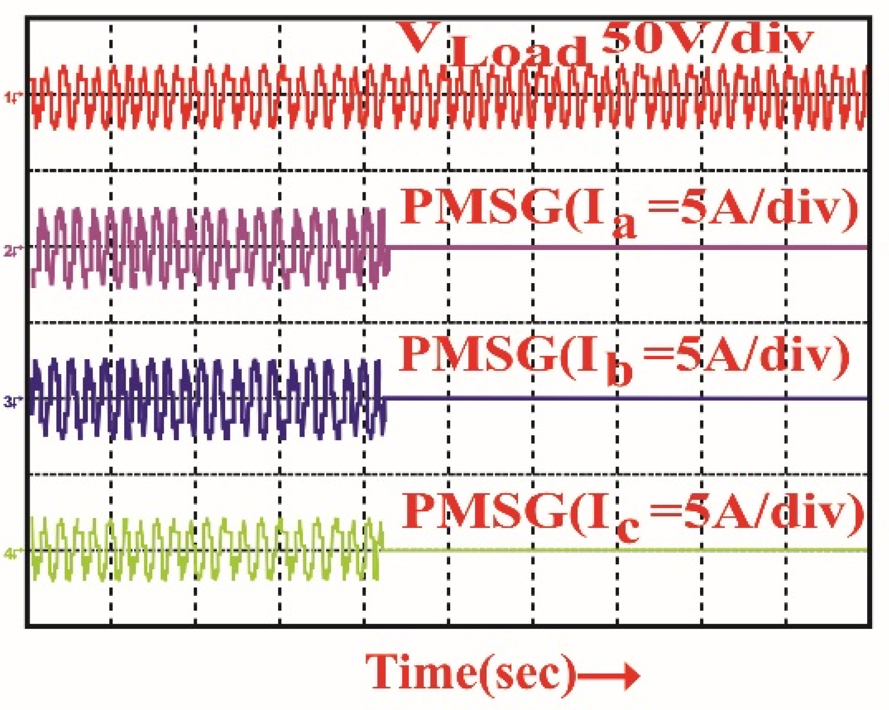
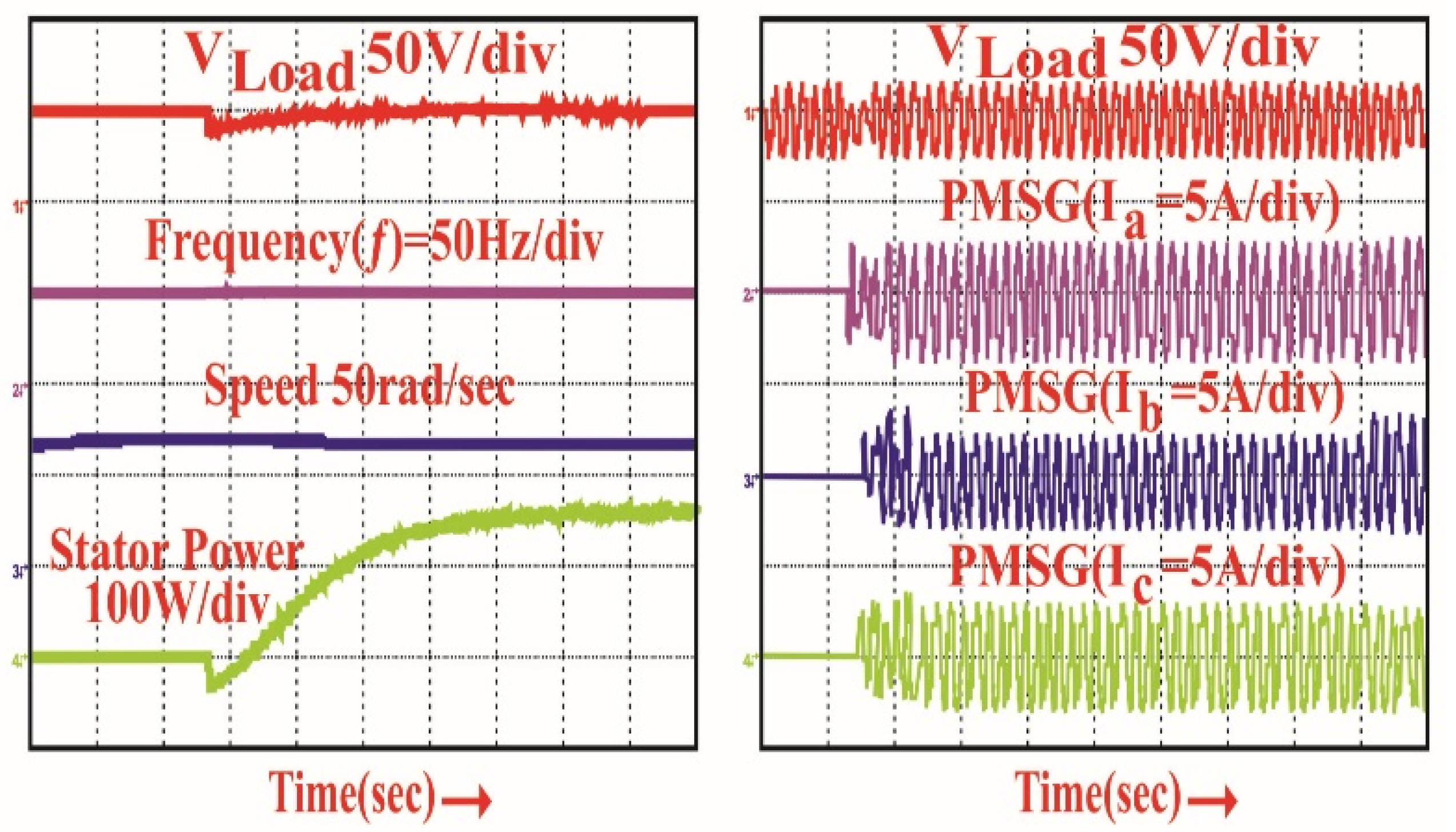
Experimental results under dynamic conditions, such as step-changed in wind speed or solar irradiation, reveal that optimal power has been tracked through the PV-Wind renewable sources and proved the validity of the proposed solution.
(v)
The two-diode model-based PV Generator provides high power extraction when compared to the single diode model.
As a future work, the paper can be extended by using the multilevel inverter with the application of advanced intelligent MPPT algorithms viz. Jaya DE, hybrid ANFIS-ABC methods.

Author Contributions

All authors contributed equally and formulated the research work to present in current version as full research article.

Funding

No funding addressed to this research activities.

Conflicts of Interest

The authors declare no conflict of interest.

Nomenclature

RSEResistance in series
RParallelResistance in parallel
TSTCTemperature at STC (Standard Test Condition)
GSTCSolar irradiance at STC
KSCoefficient of short circuit current
I P h o t o n _ S T C Photo current at STC
T C Ambient temperature
GSolar irradiation
IShort_STCShort circuit current at STC
Vopen_STCOpen circuit current at STC
VThermalDiode thermal voltage
KVLVoltage temperature coefficient
ρa,dAir density ρa,d
ωGSpeed of generator
ωGMPeak allowed generator speed
ηgearGear ratio
EBBattery fixed voltage
VPOPolarized voltage
QBatCapacity of battery
IBatteryBattery current
AexpAmplitude of exponential zone
BexpInverse time constant exponential zone
I L A = I L B Current ripple
V0Ripple voltage
f s w i t c h i n g Switched frequency
V 0 ( N ) & I P V ( N ) Sensed voltage and current
DStep perturbation of duty ratio
dTFixed step size
KVariable power ratio
PIProportional Integral

References

  1. Tiwari, S.K.; Singh, B.; Goel, P.K. Design and Control of Micro-Grid fed by Renewable Energy Generating Sources. IEEE Trans. Ind. Appl. 2018, 54, 2041–2050. [Google Scholar] [CrossRef]
  2. Mi, Y.; Zhang, H.; Tian, Y.; Yang, Y.; Li, J.; Li, J.; Wang, L. Control and Operation of Hybrid Solar/Wind Isolated DC Micro grid. In Proceedings of the IEEE Conference and Expo Transportation Electrification Asia-Pacific (ITEC Asia-Pacific), Beijing, China, 31 August–3 September 2014; pp. 1–5. [Google Scholar]
  3. Shastry, A.; Suresh, K.V.; Vinayaka, K.U. Hybrid Wind-Solar Systems using Cuk-Sepic Fused Converter with Quasi-Z-Source Inverter. In Proceedings of the IEEE Power, Communication and Information Technology Conference (PCITC), Bhubaneswar, India, 15–17 October 2015; pp. 856–861. [Google Scholar]
  4. Kassem, A.M.; Zaid, S.A. Optimal Control of a Hybrid Renewable Wind/Fuel Cell Energy in Micro Grid Application. In Proceedings of the Nineteenth International Middle East Power Systems Conference (MEPCON), Shibin El Kom, Egypt, 19–21 December 2017; pp. 84–90. [Google Scholar]
  5. Tiwari, S.K.; Singh, B.; Goel, P.K. Design and Control of Micro-Grid fed by Renewable Energy Generating Sources. In Proceedings of the IEEE 6th International Conference on Power Systems (ICPS), New Delhi, India, 4–6 March 2016; pp. 1–6. [Google Scholar]
  6. Ahmed, J.; Salam, Z. An Enhanced Adaptive P&O MPPT for Fast and Efficient Tracking under Varying Environmental Conditions. IEEE Trans. Sustain. Energy 2018, 9, 1487–1496. [Google Scholar]
  7. Vavilapalli, V.; Umashankar, S.; Sanjeevikumar, P.; Ramachandramurthy, V.K. Design and Real-Time Simulation of an AC Voltage Regulator based Battery Charger for Large-Scale PV-Grid Energy Storage Systems. IEEE Access 2017, 5, 25158–25170. [Google Scholar] [CrossRef]
  8. Hussain, S.; Alammari, R.; Jafarullah, M.; Iqbal, A.; Sanjeevikumar, P. Optimization of Hybrid Renewable Energy System Using Iterative Filter Selection Approach. IET Renew. Power Gen. 2017, 11, 1440–1445. [Google Scholar] [CrossRef]
  9. Dramohan, K.; Padmanaban, S.; Kalyanasundaram, R.; Bhaskar, M.S.; Mihet-Popa, L. Grid Synchronization of a Seven-Phase Wind Electric Generator Using d-q PLL. Energies 2017, 10, 926. [Google Scholar] [CrossRef]
  10. Szeidert, I.; Prostean, O.; Filip, I.; Vasar, C.; Mihet-Popa, L. Issues regarding the modeling and simulation of wind energy conversion system’s components. In Proceedings of the International Conference on Automation, Quality & Testing, Robotics (AQTR 2008), Cluj-Napoca, Romania, 22–25 May 2008; pp. 225–228. [Google Scholar]
  11. Mihet-Popa, L.; Bindner, H. Simulation models developed for voltage control in a distribution network using energy storage systems for PV penetration. In Proceedings of the 39th Annual Conference of the IEEE Industrial Electronics Society, Vienna, Austria, 10–13 November 2013; pp. 7487–7492. [Google Scholar]
  12. Maheswaran, G.; Hidayathullah, M.; Ismail, B.C.; Mihet-Popa, L.; Sanjeevikumar, P. Energy Management Strategy for Rural Communities’ DC Micro Grid power system structure with Maximum Penetration of Renewable Energy Sources. Appl. Sci. 2018, 11, 585. [Google Scholar] [CrossRef]
  13. Priyadarshi, N.; Kumar, V.; Yadav, K.; Vardia, M. An Experimental Study on Zeta buck-boost converter for Application in PV system. In Handbook of Distributed Generation; Springer: Cham, Switzerland, 2017; pp. 393–406. [Google Scholar]
  14. Priyadarshi, N.; Anand, A.; Sharma, A.K.; Azam, F.; Singh, V.K.; Sinha, R.K. An Experimental Implementation and Testing of GA based Maximum Power Point Tracking for PV System under Varying Ambient Conditions Using dSPACE DS 1104 Controller. Int. J. Renew. Energy Res. 2017, 7, 255–265. [Google Scholar]
  15. Kumar, N.; Hussain, I.; Singh, B.; Panigrahi, B.K. Framework of Maximum Power Extraction from Solar PV Panel using Self Predictive Perturb and Observe Algorithm. IEEE Trans. Sustain. Energy 2017, 9, 895–903. [Google Scholar] [CrossRef]
  16. Elgendy, M.A.; Zahawi, B.; Atkinson, D.J. Assessment of the Incremental Conductance Maximum Power Point Tracking Algorithm. IEEE Trans. Sustain. Energy 2013, 4, 108–117. [Google Scholar] [CrossRef]
  17. Zamora, A.C.; Vazquez, G.; Sosa, J.M.; Rodriguez, P.R.M.; Juarez, M.A. Efficiency Based Comparative Analysis of Selected Classical MPPT Methods. In Proceedings of the IEEE International Autumn Meeting on Power, Electronics and Computing, Ixtapa, Mexico, 8–10 November 2017; pp. 1–6. [Google Scholar]
  18. Abu-Rub, H.; Iqbal, A.; Ahmed, S.K.M.; Peng, F.Z.; Li, Y.; Baoming, G. Quasi-Z-Source Inverter-Based Photovoltaic Generation System with Maximum Power Tracking Control Using ANFIS. IEEE Trans. Sustain. Energy 2013, 4, 11–20. [Google Scholar] [CrossRef]
  19. Mohamed, A.A.S.; Berzoy, A.; Mohammed, O. Design and Hardware Implementation of FL-MPPT Control of PV Systems Based on GA and Small-Signal Analysis. IEEE Trans. Sustain. Energy 2017, 8, 279–290. [Google Scholar] [CrossRef]
  20. Wang, L.; Singh, C. Population-Based Intelligent Search in Reliability Evaluation of Generation Systems with Wind Power Penetration. IEEE Trans. Power Syst. 2008, 23, 1336–1345. [Google Scholar] [CrossRef]
  21. Koad, R.B.A.; Zobaa, A.F.; El-Shahat, A. A Novel MPPT Algorithm Based on Particle Swarm Optimisation for Photovoltaic Systems. IEEE Trans. Sustain. Energy 2017, 8, 468–476. [Google Scholar] [CrossRef]
  22. Priyadarshi, N.; Sharma, A.K.; Azam, F. A Hybrid Firefly-Asymmetrical Fuzzy Logic Controller based MPPT for PV-Wind-Fuel Grid Integration. Int. J. Renew. Energy Res. 2017, 7, 1546–1560. [Google Scholar]
  23. Sundareswaran, K.; Sankar, P.; Nayak, P.S.R.; Simon, S.P.; Palani, S. Enhanced Energy Output from a PV System Under Partial Shaded Conditions Through Artificial Bee Colony. IEEE Trans. Sustain. Energy 2015, 6, 18–209. [Google Scholar] [CrossRef]
  24. Kalaam, R.N.; Muyeen, S.M.; Al-Durra, A.; Hasanien, H.N.; Al-Wahedi, K. Optimisation of controller parameters for grid tied photovoltaic system at faulty network using artificial neural network-based cuckoo search algorithm. IET Renew. Power Gen. 2017, 11, 1517–1526. [Google Scholar] [CrossRef]
  25. Priyadarshi, N.; Padmanaban, S.; Mihet-Popa, L.; Blaabjerg, F.; Azam, F. Maximum Power Point Tracking for Brushless DC Motor-Driven Photovoltaic Pumping Systems Using a Hybrid ANFIS-FLOWER Pollination Optimization Algorithm. Energies 2018, 11, 1067. [Google Scholar] [CrossRef]
  26. Priyadarshi, N.; Padmanaban, S.; Maroti, P.K.; Sharma, A. An Extensive Practical Investigation of FPSO-Based MPPT for Grid Integrated PV System Under Variable Operating Conditions with Anti-Islanding Protection. IEEE Syst. J. 2018, PP, 1–11. [Google Scholar] [CrossRef]
  27. Priyadarshi, N.; Padmanaban, S.; Bhaskar, M.S.; Blaabjerg, F.; Sharma, A. A Fuzzy SVPWM Based Inverter Control Realization of Grid Integrated PV-Wind System with FPSO MPPT Algorithm for a Grid-Connected PV/Wind Power Generation System: Hardware Implementation. IET Electr. Power Appl. 2018, 12, 962–971. [Google Scholar] [CrossRef]
  28. Alanisamy, R.; Mutawakkil, A.U.; Selvakumar, K.; Karthikeyan, D. Modelling and simulation of z source inverter based grid connected PV system. In Proceedings of the 2014 IEEE International Conference on Computational Intelligence and Computing Research, Coimbatore, India, 18–20 December 2014; pp. 1–4. [Google Scholar]
  29. Kumaran, B.A.; Sekhar, C.S.A.; Bala, V. PV Powered Quasi Z-Source Inverter for Agricultural Water Pumping System. In Proceedings of the Third International Conference on Science Technology Engineering & Management (ICONSTEM), Chennai, India, 23–24 March 2017; pp. 544–549. [Google Scholar]
  30. Haji-Esmaeili, M.M.; Babaei, E.; Sabahi, M. High Step-Up Quasi-Z Source DC-DC Converter. IEEE Trans. Power Electron. 2018, 1. [Google Scholar] [CrossRef]
  31. Zhou, Y.; Liu, L.; Li, H. A High-Performance Photovoltaic Module-Integrated Converter (MIC) Based on Cascaded Quasi-Z-Source Inverters (qZSI) Using eGaN FETs. IEEE Trans. Power Electron. 2013, 28, 2727–2738. [Google Scholar] [CrossRef]
  32. Kayiranga, T.; Li, H.; Lin, X.; Shi, Y.; Li, H. Abnormal Operation State Analysis and Control of Asymmetric Impedance Network-Based Quasi-Z-Source PV Inverter (AIN-qZSI). IEEE Trans. Power Electron. 2016, 31, 7642–7650. [Google Scholar] [CrossRef]
  33. AsSakka, A.O.; Hassan, M.A.M.; Senjyn, T. Small signal modeling and control of PV based QZSI for grid connected applications. In Proceedings of the 2017 International Conference on Modern Electrical and Energy Systems (MEES), Kremenchuk, Ukraine, 15–17 November 2017. [Google Scholar] [CrossRef]
  34. Tey, K.S.; Mekhilef, S.; Seyedmahmoudian, M.; Horan, B.; Oo, A.T.; Stojcevski, A. Improved Differential Evolution-based MPPT Algorithm using SEPIC for PV Systems under Partial Shading Conditions and Load Variation. IEEE Trans. Ind. Inform. 2018, 1. [Google Scholar] [CrossRef]
  35. Jain, S.; Shadmand, M.B.; Balog, R.S. Decoupled Active and Reactive PowerPredictive Control for PV Applications using a Grid-tied Quasi-Z-Source Inverter. IEEE J. Emerg. Sel. Top. Power Electron. 2018, 1. [Google Scholar] [CrossRef]
  36. Liu, Y.; Ge, B.; Abu-Rub, H. Modelling and controller design of quasi-Z-sourcecascaded multilevel inverter-based three-phase grid-tie photovoltaic power system. IET Renew. Power Gen. 2014, 8, 925–936. [Google Scholar] [CrossRef]
  37. Amini, M.H.; Broojeni, K.G.; Dragičević, T.; Nejadpak, A.; Iyengar, S.S.; Blaabjerg, F. Application of Cloud Computing in Power Routing for Clusters of MicrogridsUsing Oblivious Network Routing Algorithm. In Proceedings of the 19th European Conference on Power Electronics and Applications (EPE’17 ECCE Europe), Warsaw, Poland, 11–14 September 2017; pp. P.1–P.11. [Google Scholar]
  38. Mohammadi, A.; Dehghani, M.J.; Ghazizadeh, E. Game Theoretic Spectrum Allocation in Femtocell Networks for Smart Electric Distribution Grids. Energies 2018, 11, 1635. [Google Scholar] [CrossRef]
  39. Vigneysh, T.; Kumarappan, N. Operation and Control of Hybrid Microgrid Using ZSource Converter in Grid Tied Mode. In Proceedings of the 2nd International Conference on Applied and T heoretical Computing and Communication Technology (iCATccT), Bangalore, India, 21–23 July 2016; pp. 318–323. [Google Scholar]
Figure 1. A block diagram with the structure of Hybrid PV-Wind micro grid system.
Energies 11 02277 g001
Figure 2. Equivalent circuit model of a PV cell with double diodes and a series and parallel resistance.
Energies 11 02277 g002
Figure 3. CPR (Performance coefficient) Vs tip speed (λT.S) curve is plotted for different βP.B (Pitch blade angle).
Energies 11 02277 g003
Figure 4. Electric equivalent circuit-based battery model.
Energies 11 02277 g004
Figure 5. SEPIC converter equivalent circuit.
Energies 11 02277 g005
Figure 6. Working model of MPRVS based P&O technique.
Energies 11 02277 g006
Figure 7. Equivalent power circuit of Quasi Z-source inverter.
Energies 11 02277 g007
Figure 8. The equivalent model of Quasi Z-source inverter governing non-shoot through the state.
Energies 11 02277 g008
Figure 9. Equivalent model of Quasi Z-source inverter in shoot through the state.
Energies 11 02277 g009
Figure 10. Developed experimental setup of the proposed hybrid micro grid system based on a real-time digital simulator-dSPACE platform.
Energies 11 02277 g010
Figure 11. Experimental results (a) during a step-changed in wind speed; (b) wind power; and (c) Duty cycle of Cuk converter.
Energies 11 02277 g011
Figure 12. PV system responses under step-changes in solar irradiation.
Energies 11 02277 g012
Figure 13. (a) Capability of the proposed hybrid micro grid under varying wind velocity and constant solar irradiation; (b) Behavior responses of the hybrid micro grid under varying solar irradiance and constant wind velocity.
Energies 11 02277 g013
Figure 14. The performance of the hybrid micro grid (a) load cutting condition; (b) Load removing condition.
Energies 11 02277 g014
Figure 15. The performance of the wind generator is evaluated under disconnecting operating conditions to the micro grid.
Energies 11 02277 g015
Figure 16. The performance of the wind generator is evaluated under reconnecting operating conditions to the micro grid.
Energies 11 02277 g016
Table 1. SEPIC converter parameter.
SI. No.ParametersValue
1.Inductors ( L A = L B )0.42 mH
2.Capacitors ( C A = C B )3.5 × 10⁻³ µF
3.Current ripple ( I L A = I L B )0.5 A
4.Voltage ripple ( V o )1 × 10⁻³ V
5.Switching frequency ( f s w i t c h i n g )20 Hz

