Review

Evaluating the Effect of Metal Bipolar Plate Coating on the Performance of Proton Exchange Membrane Fuel Cells

by
Oluwatosin Ijaodola
1,
Emmanuel Ogungbemi
1,
Fawwad Nisar. Khatib
1,
Tabbi Wilberforce
1,
Mohamad Ramadan
2,3,
Zaki El Hassan
1,
James Thompson
1 and
Abdul Ghani Olabi
4,5,*
1
Institute of Engineering and Energy Technologies, University of the West of Scotland, Glasgow G72 0AG, UK
2
Department of mechanical engineering, International University of Beirut, P.O. Box 146404, Beirut, Lebanon
3
Associate Member at FCLAB, CNRS, Université Bourgogne Franche-Comté, 90010 Belfort CEDEX, France
4
Department of Sustainable and Renewable Energy Engineering, University of Sharjah, P.O. Box 27272, Sharjah, UAE
5
Mechanical Engineering and Design, School of Engineering and Applied Science, Aston University, Aston Triangle, Birmingham B4 7ET, UK
*
Author to whom correspondence should be addressed.
Energies 2018, 11(11), 3203; https://doi.org/10.3390/en11113203
Submission received: 19 October 2018 / Revised: 10 November 2018 / Accepted: 13 November 2018 / Published: 18 November 2018
(This article belongs to the Special Issue 10 Years Energies - Horizon 2028)

Abstract

:
Environmental concerns of greenhouse gases (GHG) effect from fossil commodities and the fast increase in global energy demand have created awareness on the need to replace fossil fuels with other sources of clean energy. PEM fuel cell (PEMFC) is a promising source of energy to replace fossil fuels. The commercialization of the cell depends on its price, weight and mechanical strength. Bipolar plates are among the main components of PEMFC which perform some significant functions in the fuel cell stack. Metal bipolar plate is considered by the research community as the future material for fuel cells. However, surface coating is required for metals to enhance its corrosion resistance, hydrophilicity and interfacial contact resistance (ICR) in PEM fuel cells. Open pore cellular metal foam (OPCMF) materials have been used to replace the conventional flow field channel in recent times due to its low electrical resistance, high specific area and high porosity; however, it endures the same corrosion problem as the metallic bipolar plate. This investigation offers an overview on different types of bipolar plates and techniques in coating metallic bipolar platse and open pore metal foam as flow field channel materials to improve the corrosion resistance which will eventually increase the efficiency of the fuel cell appreciably.

1. Introduction

The increase of world energy demand and rise in consumption due to fast growing human population has brought about the need to substitute current sources of energy to reduce world reliance on fossil commodities. Also, environmental concerns of the effect of fossil fuel due to greenhouse gases (GHG) emission have brought about the urgent need for an alternative fuel. The GHG such as nitrous oxide (N2O), methane (CH4), and carbon dioxide (CO2) etc. do result in air pollution, global warming and climate change [1,2]. Aside from the energy demand and environmental challenges, sustaining fossil fuels as a global main energy source is uncertain, because of the unrest in many of the oil producing countries, unstable crude oil prices and its finite nature. Therefore, it is important that alternative energy to fossil fuels is clean and renewable. Proton exchange membrane fuel cells (PEM fuel cells) are among the promising fuels that are currently being developed in replacing fossil fuels. PEM fuel cell is a device that transforms hydrogen and oxygen into electrical energy via an electrochemical reaction and the by-products are water and heat. The automotive industry, stationary industry and portable power generation industry are targeting fuel cells as prospect sources of energy for their product. PEM fuel cells have the advantages of quick start-up, swift response to load variation, high power density and low operating temperature [3,4]. A single fuel cell comprises of a current collector, bipolar plate, flow field channels, gas diffusion layer, catalyst layer, and membrane electrode assembly. A five-cell stack PEM fuel cell and a fan attached to it is shown in Figure 1. A basic PEM fuel cell operation involves the oxidation of hydrogen at the anode and air or oxygen reduction at the cathode. A single PEM fuel cell produces a practical voltage of 0.9–1.229 V. In order to get more voltage output, two or more cells needs to be stacked in a series [5].
A bipolar plate is a very vital element of a fuel cell stack. It constitute about 80% of the overall weight and around 45% of the stack total cost [6]. The primary functions of bipolar plates are: It provides mechanical strength and supports the membrane electrode assembly, provides uniform distribution of reactant gases within the cell, helps in facilitating heat and water management in the cell, and provides electrical connections among individual cells [7,8,9]. Bipolar plates are designed with gas flow field channels, manifolds and land to improve the reactant gases’ distribution and transport as shown in Figure 2.
The flow field channel design supports in providing a uniform distribution of gases across the active electrode area. The channels assist in providing pathways for the reactant gases to the catalyst layer through a gas diffusion layer (GDL), whereas lands make possible electron transportation through the GDL. Conversely, manifolds take the reactant gases and end products in and out of the bipolar plates. Table 1 shows the established set targets of the United States Department of Energy (DOE) for bipolar plate’s materials requirement, in respect to cost and performance.
Tawfik et al. [3] compiled a list containing the expected features required of bipolar material in the transportation sector.
  • It must be light in weight;
  • Does not melt and produce metallic ions;
  • A high mechanical strength less than 200 Nm−2;
  • High corrosion resistance with corrosion current at 0.1 V and H2 purge < 16 Acm−2;
  • Cost-effective mass production: US$ 10 kW−1
  • High corrosion resistance with corrosion current at 0.6 V and air purge < 16 Acm−2;
  • Interfacial contact resistance (ICR) @140 Ncm−2 = 20 m cm2;
  • The ohmic resistance must be low and steady all through the operation;
  • The surface tension must be high with a water contact angle close to 90 °C (i.e., high dehydration).
The conventional material for fuel cells bipolar plate is graphite because of its low density, high chemical stability, high corrosion resistance, low bulk resistivity and little electrical resistance. However, graphite is fragile and expensive which makes it not ideal for mass production. Therefore, other materials like metals and polymer composites have drawn the attention of researchers as possible replacement [12]. Metal bipolar plates are seen as a potential material for bipolar plate because of its advantages such as: high electrical conductivity, good thermal conductivity, mechanical strength, and it can be formed into the desired shape [13]. On the other hand, metals are susceptible to corrosion in both acidic and humid operating environments.
Metals decompose when the fuel cells are operating within a pH 2–4 and an operating temperature of 80 °C [13,14]. The MEA may be affected due to ion leaching which will cause low power output of the cell. Also, during operating conditions, the corrosion layer formed increases the electrical resistance of the fuel cells. In solving this problem, coating of metal bipolar plates is suggested. In recent times, investigations have been conducted on polymer composite bipolar plates due to its lightweight, it is easy to machine or mould, and it has good corrosion resistance. However, when compared with metallic bipolar plates, it has low impermeability to gases and low mechanical strength and conductivity. High electrical conductivity is a challenge to achieve with composite bipolar plate as a result of high filler contents, which are important to influence adequate electrical conductivity [15]. Table 2 shows the properties of different types of bipolar plates. This paper considers an extensive review of the recent research being explored on various types of materials for bipolar plates detailed in the following section. A thorough discussion on different corrosion protection techniques and characterisation of coated metal bipolar plates are reported in Section 2. A broad variety of ways of protecting metallic bipolar plates including open pore cellular foam from the cell’s corrosive environment will be discussed in Section 3. The effect of ionic contamination within the cell is reported in Section 4 followed by conclusions in Section 5.

1.1. Materials for Bipolar Plate

There are several materials used for manufacturing bipolar plates in proton exchange membrane fuel cells. These materials are either metallic or carbon based. There are several research and development activities carried out on graphite. This is because of the characteristics of graphite when used in harsh conditions. Graphite’s application in fuel cells was mainly for stationary purposes where the weight as well as the volume of the material was not critical. Using graphite as a flow plate has some limitation especially in terrestrial applications [16]. Again, matching the flow channels is very expensive and this adds up to the total cost of the cell. The limitations of the graphite plates gave rise to the metallic flow plates. Metals have good thermal and electrical conductivity. Metals also have low manufacturing cost as well as good gas permeability. These materials also have some demerits as well. In a harsh environment that is corrosive, it becomes chemically unstable and this results in corrosion. Corrosion can easily result in contamination of the membrane electrode assembly, reducing the overall performance of the cell. This results in an increase in the interfacial contact resistance of the flow plates. The next sections in this report will thoroughly cover the various characteristics of materials used as bipolar plates in fuel cells [17].

1.2. Graphite Bipolar Plate

Graphite bipolar plate is extensively adopted to be the standard for other bipolar plate’s fabrication due to its high corrosion resistance in a humid and acidic environment and good chemical stability within a PEM fuel cell [16]. Again, it possesses some advantages such as little contact resistance, low density, high corrosion resistance, and good thermal and electrical conductivity. However, there have been concerns over its poor mechanical strength which is noted for reducing the plate’s thickness, which results in low volumetric power density [17]. This makes it unsuitable for mobile and transportation applications. Graphites are filled with resin to block the pores, so as to enhance gas impermeability. The fabrication of the flow field channels is integrated by a computer numerical control machine which is time-consuming and expensive; this hinders it from large scale production [16,17,18]. Graphite is a crystalline form of carbon which comprises of atoms covalently bonded by three near atoms, leaving one free electron unbonded to facilitate the highly wanted electrical conductivity of the plates. However, the bond energy in the planes are more than the bond amid layers, which results in a weaker flexural strength and has a high propensity for fracture during fabrication when compared to other materials of bipolar plates that are adopted [19]. To optimize the properties of graphite, attention must be given to nature, degree of crystallinity, size, and morphology, and the percolation threshold must be determined. Graphite can be classified into natural graphite which possesses higher crystallinity, or synthetic graphite which possesses lesser crystallinity and consequently lower electrical conductivity [20]. The electrical conductivity of natural graphite is varied based on the geographical origin of the extraction, the milling and sieving involved in the processing operation and the alterations made to the size and particle morphology. Due to this wide range of possibilities, synthetic graphite with diverse purities and degrees of crystallinity are available with variations in grain sizes, surface areas and electrical conductivity [21].

1.3. Polymer Composite Bipolar Plate

Polymer composite bipolar plates have different advantages, for instance, low weight and cost, good gas tightening, low contact resistance, excellent corrosion resistance, and the eradication of the machining process required when producing graphite and metallic bipolar plates [22,23]. However, a major disadvantage related to the polymer composite bipolar plate is its poor electrical conductivity. Increasing the electrical conductivity needs a high filler which is difficult to process and reduces the mechanical strength, an important requirement for automotive industry [24,25]. As a result, achieving a maximum balance between electrical conductivity and mechanical strength is essential for carbon-polymer composites to materialise as an alternative bipolar plate. The content of carbon, ranges between 50% to 80% by weight which determines the electrical conductivity and mechanical performance of the bipolar plates [26]. Composite bipolar plate’s electrical conductivity can be increased by integrating conductive polymeric materials of organic base. The conductive polymer material is chosen by the cost and process, chemical suitability, and mechanical and thermal stability. The materials for conductive polymeric flow are categorized into intrinsically conducting polymers (ICP) and conductive polymeric composites (CPC). ICP uses chain unsaturation and electron delocalization to greatly facilitate electrical conductivity. However, it has high manufacturing cost and poor productivity. On the other hand, CPC combine mainstream polymers such as Acrylonitrile Butadiene Styrene, polycarbonate, polypropylene, including fillers of conductive loads like carbon black, metallic powders or metallic fibers. This combination results in the realization of polymeric composite materials that present electrical properties [26]. However, while this design enhances electrical conductivity, it reduces mechanical efficiency. The mass variation in its electrical conductivity coupled with the low cost of manufacturing makes it a preference over ICP.
Polymer composites involve the use of graphite filler or hot moulding of carbon in thermoplastic or thermosetting composite resins with advantages such as low weight; flexibility; and economical production processes like injection or transfer molding processes, compression and corrosion resistance [27]. Thermosetting resins which comprise of polyester, epoxies and vinyl ester have been commonly used due to their excellent corrosion resistance which is cross-linked in a curing process to increase chemical resistance. Thermoplastic resins which comprise of polyethylene, polypropylene, poly vinylidene fluoride, and liquid crystalline polymer, and poly phenylene sulfide are more suited for automated manufacturing because it can undergo injection-molding [28,29]. However, thermoset resins are chemically unstable when operating at lower temperatures in a PEM fuel cell which makes it not recommendable for bipolar plates. Injection molding is limited due to the introduction of filler loadings leading to an overall increment in viscosity [30]. Thermoplastic composites are mostly comprised of graphite powder in poly-vinylidene fluoride, being sometimes reinforced with small carbon fibers [31]. Table 3 compares the thermoset/filler composite with thermoplastic/filler composite in a composite bipolar plate material. Thermoplastic composites offer longer process cycles than thermosetting resins because the former must be cooled before removal from the mould is possible.
Advantages presented by these composite materials such as graphite/vinyl ester composite include the reduced brittleness in comparison with machined graphite and better corrosion resistance than metallic bipolar plates [32]. Additionally, composite designs have commercially available raw materials, which possess low bulk weight and are less expensive [33]. Researchers in this field introduced the use of a polymer and graphite composite, where polymer functions to bind the flexible layered structure, which provides higher electrical and thermal conductivity. This composition consists of graphite flakes expanded by intercalation of highly concentrated acid leading to separation of graphite sheets into nano-platelets [34].

1.4. Metallic Bipolar Plates

Metal bipolar plates have several benefits when used in fuel cells, like low gas permeability; cost effectiveness; easy manufacturing process; good electrical and thermal conductivity; high formability and machinability; and good mechanical properties like shock resistance, strength and durability [35,36,37]. These types of bipolar plates have made it possible to manufacture mass production cost-effective plates which make it attractive to the government and private organizations. Metals like stainless steel and aluminum are able to perform properly as normal bipolar plates when machined to 0.1 inches thick and 0.05 inches thick sheets, respectively, if they utilize bipolar plates as a coolant [38]. However, metallic bipolar plate suffers from corrosion and the forming of a thin oxide layer on a plate surface, due to poor chemical stability when exposed to a corrosive environment [36,37,38]. Ni2+, Fe3+ and Cr3+ are examples of by-products in a fuel cell corrosion environment. The by-products are poisonous to the catalyst layer and solid polymer electrolyte. The oxide layer formed due to corrosion makes the cell performance less effective due to the increase of ICR that occurred amid the metal bipolar plates and GDL. It is found that this type of bipolar plate dissolves in PEM fuel cell operating conditions of pH level of 2–3 and a temperature of 80° [39]. Antunes et al. [40] stated that corrosion and dissolution of metallic bipolar plates hinders cell performance in the following ways:
  • It causes a rise in the contact resistance among the metallic bipolar plate and GDL.
  • There will be an important change to the plate surface, hereby decreasing the area of contact with the GDL.
  • The metal ions diffusion in the membrane and significant trapping of the metal ions in the catalyst sites will lead to ionic conductivity diminution and fuel cell malfunction.
Attempts to prevent corrosion and interfacial contact involve the use of corrosion-resistant thin conductive and protective layers in coating the metal plates. A relatively wide range of metals have been used in fabricating bipolar plates such as stainless steel, aluminium, and alloys such as titanium alloys, copper alloys and nickel alloys [41]. The high cost of using Hf, Ta, Nb, Ti and Zr for bipolar plates forced the use of iron-based materials even though these noble metals exhibit superior performance [42]. Hornung and Kappelt [43] found that iron alloys containing Cr, Mo, N and Ni exhibited corrosion resistance similar to the more expensive gold-plated plates. Stainless steel and titanium are well suited for mass production and stability in low pH environments, providing very good mechanical properties, very low permeation of gas and good corrosion resistance as a protective film of oxide metal, which is made on the surface in the presence of oxygen. However, this protective film insulates the metal, adversely affecting conductivity and removal or reduction of the thickness of the protective layer is necessary, replacing it with a conductive corrosion-resistant film [44]. Recent researches are mostly populated with studies on stainless steel (SS) as a bipolar plate material, on the different compositions of SS and their behaviors under various conditions being applicable to different working purposes [45]. Wang et al. [46] discovered that since Cr can form a passive film on the surface of SS, higher Cr composition increases corrosion resistance of stainless steel bipolar plates. Comparing ferritic stainless-steel samples AISI1434, AISI1436, AISI441, AISI444, and AISI446, it was discovered that AISI446 is best in bipolar plate capacities [4]. Davies et al. [47] chose three types of stainless steel and tested them under conditions like a PEM fuel cell and reported a disparity in their performances. They determined the thickness of passive film formed on the SS bipolar plates using Auger Electron Spectroscopy (AES) and discovered that as the alloy element content decreased the film thickness decreased as well. A conclusion was reached, that if the chemical formation of the metallic alloy bipolar plates is optimized, non-coated metal alloys can be used without trading-off for the lesser performance of graphite bipolar plates. The 316L and 316 SS bipolar plates are commonly coated when used in fuel cells due to their cost and they are naturally protected by a passive layer [48]. Wang and Northwood [49] experimented with 316L SS bipolar plates by coating them with TiN through physical vapor deposition (PVD) in order to enhance the corrosion resistance. The electrochemical impedance test shows that the coated TiN SS316L was much higher than its counterpart (uncoated SS316L) throughout the curves as shown in Figure 3. They also noticed that the potentiodynamic test followed the same trend. They reached a conclusion that 316L stainless steel bipolar plates can be coated in order to avoid corrosion.
Research is not limited to the 316 types, Chih et al. [50] investigated carbon-coated 304 SS type plates, integrating them into one-cell and three-cell PEM fuel cells. Using chemical vapour deposition (CVD), a carbon film was deposited on nickel-plated 304SS bipolar plates. The corrosion resistance was compared with Poco graphite bipolar plate and uncoated 304SS bipolar plates. The carbon-coated substrate performed better with higher electrical conductivity and a tolerable measure of corrosion resistance was reported. Lafront et al. [51] studied SS (316L) and Zr75Ti25(AB) alloy bulk amorphous in a PEM fuel cell-simulated environment at 25 °C and 80 °C, by using the electrochemical noise (EN) method. They recorded the stability of the passive films in cathodic conditions, and instability due to pitting corrosion caused by hydrogen content in anodic conditions. It was concluded that on the anode side the AB alloy performed better than the stainless steel. However, at the cathode side, the reverse is the case.

2. Coating with Metal Nitrides

Metal nitride is used for coating metallic bipolar plates and it is known for its good electrical conductivity, chemical stability and excellent hardness. It provides electrical conductive protection and pinhole-free corrosion resistance [39]. There is a lot of research that has been carried out using nitride-based alloys for bipolar plate protection so as to boost corrosion resistance with no sacrifice of other significant properties like thermal and electrical conductivity. Nguyen et al. [52] investigated the multi-coatings of CrN/TiN, used to protect 316L stainless steel substrates. The CrN/TiN film was deposited at various thickness proportions by magnetron sputtering to assess the electrochemical behavior on three samples. The coated substrate exhibited greater corrosion resistance and higher charge transfer resistance than the non-coated substrates. The ICR results show good surface conductivity. The electrochemical test shows that high chemical inertness and the deposition of the coating were faster. This result was because of the crystalline nature of the multi-layer CrN/TiN coating. They concluded that the technology is suitable for low cost manufacturing and the coating is suitable for metallic bipolar plates. Bo et al. [53] used a succession of CrN films deposited on SS substrates by pulsed bias arc ion plating (PBAIP) techniques, at varying N2 flow rates to examine the corrosion resistivity. Characterized by X-ray photoelectron spectroscopy and X-ray diffractometry, the ICR was measured by Wang’s method. The results revealed that the corrosion resistance of the coated SS substrate was better than the non-coated steel substrates [53]. Tian [54] conducted an experiment involving the use of chromium nitride/Cr coating deposited by physical vapour deposition (PVD) on the facet of 316L SS. In a corrosive condition of 0.05 M H2SO4 +2 ppm F, a potentiostatic polarization test was carried out at the anode and cathode side operation potentials. Chromium nitride/Cr coated SS substrate exhibited enhanced corrosion resistance, higher chemical stability in both the anodic and cathodic conditions and three times less interfacial contact resistance than non-coated substrates. An investigation carried out by Jinlong et al. [55] synthesized niobium nitrides layer on 316L stainless steel plates by studying the electrical behaviour and corrosion properties of 316L SS for suitability as bipolar plates in PEMFC conditions. Due to the nitriding condition selected, only Cr2N was formed. It was then compared to a CrN + Cr2N coating. The results signify that the Cr2N coated stainless steel exhibited better corrosion resistance and lower interfacial contact resistance. Dongming et al. [56] used a multi-arc ion plating (MIP) technique in depositing titanium nitride (TiN) on a titanium bipolar plate, as revealed in Figure 4. The result shows that the TiN film improved the corrosion resistance of the pure Ti bipolar plates in a single fuel cell setup operated without degradation of power output for over 1000 h.
A similar experiment by Li et al. [57] used the 316-stainless steel as substrate, coating it with TiN before exposing the coated sample in 0.01 M HCl + 0.01 M Na2SO4 solution. It was observed that the TiN coated 316SS substrate displayed a better corrosion resistance and electrical conductivity under cathodic and anodic environments. It was further observed that while the non-coated substrate passivated after immersion tests in both the O2 and H2 environment. Another research by Wang et al. [58] examined the interfacial contact resistance and the electrochemical properties of 316L SS substrates coated with CrN, TiN and TiAIN deposited by electron beam physical vapour deposition (EBPVD) in a fuel cell environment. 1 M H2SO4 at 70 °C purged with O2 or H2 as was used as a corrosive solution as the potentiodynamic polarization analysis was conducted at anodic and cathodic operating conditions for 4 h. Contact resistance of the coated substrates was lower than the non-coated samples, while for the corrosion resistance, CrN coating performed better in the anodic environment. The CrN coating was recommended by the researchers. Further research on the suitability of CrN involved the initial coating Cr2N and Cr mixture with single phase CrN. It was seen that passive film formed on the chromium nitride surface because of the galvanic coupling sandwiched between the substrate and coating which significantly influenced the performance. Results showed that the CrN coated 316L stainless steel substrate exhibited significantly higher corrosion resistance, surface and conductivity, and lower contact resistance than non-coated substrates. Work done by Mats et al. [59] involves the deposition of TiN/NbN multilayer coatings on high speed steel and substrates of cemented carbide, by using electron beam evaporation and D.C. magnetron sputtering techniques comprising of a reactive hybrid deposition method. X-ray diffraction, transmission electron microscopy, Rutherford backscattering spectroscopy and Auger electron spectroscopy were used in characterizing the four different multilayer coatings with periodicity of 500/500 nm, 100/10 nm, 10/100 nm and 10/5 nm and the homogeneous TiN and NbN layers that were deposited. Both the homogeneous layers and the multilayers exhibited cubic structures like NaCl. The 10/5, 10/100 and homogeneous NbN coating exhibited the maximum hardness of about 3400 HV and all the coatings had a dense columnar microstructure. They reached a conclusion that these methods of coating work better for cemented carbide substrate than steel. Lixia et al. [60] studied AISI 304 stainless steel (SS) coated with niobium nitride by using plasma surface diffusion alloying process, which consist of an outer layer of 8–9 µm thick niobium nitride and a sublayer of 1–2 µm thick Nb and N diffusion solid solution. A 0.05 M H2SO4 + 2 ppm F solution at 70 °C was used to simulate a corrosive fuel cell environment and then assess corrosion resistance of the coated substrate. It was concluded that the NbN diffusion coating significantly enhanced the corrosion resistance of SS, with the self-corrosion potentials rising to 100 mV and 143 mV and corrosion current density at anode being 0.127 µAcm−2 and 0.071 µAcm−2 at the cathode. Furthermore, the coated substrates have a lower ICR of 9.26 mΩ cm2 at compaction force of 140 N cm−2 when compared to the 100.98 mΩ cm2 showed by the non-coated substrate as shown in Figure 5.
Changhee et al. [61] deposited Tantalum nitride (TaN) film on AISI 316L SS by plasma-assisted inductively-coupled reactive magnetron sputtering under PEM fuel cell condition through electrochemical measurement techniques. After a potentiodynamic polarization test, the TaN films exhibited corrosion current densities which were significantly greater than the results obtained from the testing of metallic Ta films and 316L SS. Moreover, coated substrate exhibited greater chemical stability in simulated cell environments. Alishahi et al. [62] conducted an experiment by depositing a Ta/TaN multilayer coating on 316L SS bipolar plates so as to enhance its electrical conductivities and electrochemical properties. The coating was done by reactive magnetron sputtering. The research disclosed that the polarization resistance of Ta/TaN coated substrate was about 30 times higher at ambient temperatures and about 104 times higher at elevated temperatures. Furthermore, the coated substrates showed lower interfacial contact resistance and improved hydrophobicity. Ta/TaN coating is recommended for Stainless steel bipolar plate coating.

2.1. Coating with Metal Carbides

Metal carbides are also used in coating metallic bipolar plates so as to give a pinhole-free corrosion-resistant and electrically-conductive protection which will possess chemical inertness and high electrical conductivity. Hung et al. [63] investigated the comparison of ICR and corrosion resistance of a pure as-received Al 6061 and coated Al 6061 samples with chromium carbide using the high velocity oxygen fuel thermal spray method. Carbide used comprises of an intermediate Cr-C-Ni and top layer Cr3C2. They were incorporated into a fuel cell stack operating at 37 °C for 250 h and 80 °C for another 500 h. After 750 h of operation, the result was revealed using energy dispersive X-ray spectroscopy (EDX) analysis and scanning electron microscopy (SEM). It was revealed from the result that the coated samples improve the corrosion resistance and have a lower ICR than the uncoated samples at different compact force. Rosanna et al. [64] reported that the high velocity oxygen fuel technique (HVOF) was used to deposit cement coating consisting of chromium carbide on AISI304 substrate and the microstructure, chemical and phase compositions which were characterized by SEM techniques. In addition, the tribological behavior was assessed by a pin on disc test, the corrosion resistance evaluated by electrochemical tests in corrosive NaCl solution and the effects of 9f wear and corrosion investigated using tribocorrosion tests. After the results were shown, the chromium carbide cement coated AISI304 substrate exhibited better corrosion resistance than non-coated samples.
Stainless steel was coated with chromiun carbide, a research conducted by Huang et al. [65] simulated in a cathodic environment of a PEM fuel cell. The SEM test shows some pinhole in the coating, although the coated samples show a high corrosion resistance. In another research carried out by Ren and Zeng [66], titanium carbide coating was deposited on 304 SS bipolar plates by the use of a simple high-energy micro-arc alloying method and a metallurgy bonding was formed between the substrate and coating. In the corrosive environment of 1 M H2SO4 solution, the coated stainless-steel substrates exhibited increased corrosion prospective and greatly reduced corrosion current density from pure substrate 8.3 µA cm−2 to a coated substrate value of 0.034 µAcm−2 and the coated sample showed no observed degradation after a lifetime test of 72 h of H2SO4 solution exposure.
Laser-alloyed TiB2/TiC/Al composite was used as a coating on aluminium substrate 6082-T651—research described by Dunja et al. [67] to investigate the microstructure, corrosion resistance and chemical bonding. The TiB2/TiC/Al coating exhibited a compact design with low porosity, minimum crack and excellent corrosion resistance. Furthermore, electrostatic impedance spectroscopy test revealed that the TiB2/TiC/Al coating showed lower coating capacitance, increased polarization resistance and reduced corrosion current density compared to non-coated substrates. Finally, the pitting attack suffered by the substrate malt was greatly reduced by the TiB2/TiC/Al coating. Reza et al. studied [68] the coating of AISI L2 steel with niobium carbide (NbC) using high temperature thermo-reactive diffusion (TRD) in a sealed box. The optimized ratio of powder mixtures consisting of ferroniobium, ammonium chloride and alumina powders present were determined by the desired thickness. Results revealed that the coated substrates exhibited greatly higher wear resistance and a lower coefficient of friction than non-coated substrates. A related experiment conducted by Alejandro et al. [69] utilized the same technique to deposit niobium carbide on AISI 1045 low alloy steel, investigating the effect of ferroalloy on the corrosion resistance. Using EIS and potentiodynamic polarization methods, the corrosion resistance was measured in a corrosive environment of 3.0% NaCl. Characterization of microstructure and surface morphology was done using X-ray diffraction and SEM respectively. At the end of the research, it was noted that the amount of ferroalloy had no effect on film thickness, and that the coated substrates exhibited greater corrosion resistance. The rough interface between the substrate and the coating as well as the porosity of the coating resulted in reduction on corrosion resistance after exposure into NaCl solution for 24 h. Jiang et al. [70] coated Ti6Al4V substrate with ZrC nanocrystalline by using the double cathode glow discharge approach. The corrosion resistance of the extremely dense and homogeneous microstructure was examined using EIS, potentiodynamic and potentiostatic polarization. It was discovered that though rising temperatures caused corrosion resistance to decrease, still ZrC coated Ti-6Al-4V substrates exhibited corrosion resistance three times better than non-coated samples. Also, the ICR of ZrC coated substrate performed better than the uncoated substrate and the contact angle measurement shows that the coated Ti6Al4V exhibited a more hydrophobic nature than its counterpart as shown in Figure 6. This method of coating for bipolar plate was recommended.
From Figure 7, the potentiodynamic polarization curve for the ZrC coated and uncoated Ti-6Al-4V at varying operating temperatures is presented. There is an appreciable increase in the current density at the cathodic region when the potential reduces and the temperature increases. This phenomenon is due to the rise in temperature. Rate of reaction at the cathode region increases as the temperature increases. There is also a potential plateau at the anodic region for all the three temperatures under investigation. Increasing the temperature between 25–70 °C increases the current density at the anode region for the uncoated Ti-6Al-4V but the increase noticed on the coated ZrC sample is negligible. An increase in temperature also increases the number of defects and this exposes the passive layer at elevated temperatures. The results also indicated that the number of defects for the ZrC sample is less compared to the uncoated.
Figure 8 explains the Nyquist curve as well as the bode plot for the samples under investigation. The results generated for the ZrC sample and uncoated Ti-6Al-4V are shown as a semi circles but the radius is varying at different temperatures. An increase in temperature increases capacitance diameter in the Nyquist plot as shown in Figure 8a, but the impedance is seen to decrease drastically in Bode magnitude plot in Figure 8b, indicating a reduction in the corrosion resistance. Irrespective of the temperature, the diameter for the ZrC sample is larger than the bare Ti-6Al-4V and the phase angle is nearly −90 °C; however, the bare Ti-6Al-4V exhibits smaller electrochemical characteristics [70]. The bare Ti-6Al-4V shows two depressed semic circles but the bode plot indicates one maximum for both high and low frequency ranges. The Nyquist plot for the ZrC sample also captures one capacitive loop for the entire frequency. This clearly shows that using the sample coated with ZrC affects the overall performance of the cell based on the electrochemcial characteristics explained above.

2.2. Coating with Metal Oxide

Metal oxides provide coating on bipolar plates that improves corrosion resistance and electrical conductivity at affordable costs [4]. Heli and John [71] deposited a composite 0.6 µm thick SnO2: F on ferrite stainless steel samples AISI441, AISI444, and AISI446 using low-pressure chemical vapour deposition. The substrate steel was found to have a considerable part in the properties of the coating, as the coated substrates showed the highest corrosion resistance. While pure AISI441 exhibited highest dissolution rates, the SnO2: F coating greatly reduced dissolution. However, it was the coated AISI446 stainless steel that exhibited greatest corrosion resistance followed by the AISI444. Potentiostatic polarization and ICP tests proved that the cathode environment posed greater corrosive conditions than the anode environment and that the ICP of the coated substrates was increased. Furthermore, the corrosion resistance of the substrate was found to significantly affect the coating dissolution. A similar research by Heli et al. [72] coated austenite SS 316L, 317L and 349TM with SnO2: F 0.6µ made thickness by using low pressure chemical vapour deposition. Like in the earlier reported research, the bare steel had a noteworthy effect on the behaviour of the coated substrate. After the research, the 317L substrate steel exhibited the best cell output, a very stable low anode current, followed by the 349TM steel substrate cathode current. Furthermore, results proved that the cathodic environment was less corrosive than the anode. The coated 349TM substrate exhibited highest corrosion resistance followed by the already sufficient corrosion resistance of the 317L substrate. Finally, the coated 349TM substrate showed increased ICR while the other two coated samples exhibited decreased ICR. Mohsin et al. coated graphite oxide on copper metal. Atomic force microscope (AFM) revealed that the GO sheets, deposited using electrophoretic deposition (EPD) on copper to be about 1–2 nm thick. After optimized deposition time of about 10 s and optimized potential of 5 V, the GO coatings were 400 nm thick. In a solution of 3.5% NaCl solution, Tafel analysis and EIS was used to measure the corrosion resistance of GO-coated copper metal. Results showed that the coated samples exhibited about six times more resistance to corrosion than non-coated copper metal. Jinlong et al. [73] compared three samples of bipolar plates, amorphous nickel-phosporus, amorphous nickel-phosporus with molybdenum and amorphous nickel-phosporus with reduced graphene oxide. Using electrodeposition techniques from a nickel sulfate bath the corrosion resistance was investigated. Results showed that the amorphous nickel-phosporus with graphene coating exhibited the best corrosion resistance in the cell environment. Haneul et al. [74] studied using polyvinyl alcohol (PVA) to enhance interfacial contact bond between a facile solution-generated reduced graphene oxide (rGO) coating and an Al substrate. The PVA, leading to a large amount of hydroxyl groups on the Al surface was found to induce several conjugations between the substrate and rGO, aiding the coating process. After finishing the experiment, the rGO coated Al exhibited greater corrosion resistance than pure Al bipolar plates, and the PVA-assisted coating process exhibited even greater corrosion resistance than directly coated Al as the PVA enhanced adhesion of the film to the substrate.

2.3. Carbon Based Coating (Graphene Carbon–Based Coating)

Jianhua et al. [75] reported graphene, another carbon-based element, was used to coat aluminum in corrosive 0.5 NaCl solutions by dip coating route. The study utilized the Raman spectra analysis to observe a uniform and sequential distribution of the graphene coating on aluminum substrates. Final results in this research using the EIS and potentiodynamic polarization showed that the coated aluminum substrates were three times better than non-coated substrates in resisting corrosion. Kirkland et al. [76] used graphene to coat nickel and copper substrates and was exposed to corrosive a aqueous environment. It was observed that graphene coating affected the material differently, the dissolution of the anode for the Ni and reduction reactions on the cathode for the Cu were slowed down significantly and the graphene deposition was able to provide corrosion resistance. Adam et al. [77] studied a comparison between SS with a nickel seed layer with (Ni/SS) and muli-layered graphene film coated by chemical vapour deposition (CVD) on stainless steel with nickel seed layer with (G/Ni/SS). Raman spectroscopy was used to analyse the result and it showed that there was no considerable benefit of the G/Ni/SS over Ni/SS in a short/medium term corrosion test because there result was similar. However, when the corrosion test was carried out over a long term there was an obvious superiority of G/Ni/SS coating because it indicates no defect while for Ni/SS there was degradation, as seen in Figure 9, showing the optical images of the substrates before and after atlas cell test. There were dark marks on the G/Ni/SS of the graphene coated plates even before carrying out the test.
Further research on graphene coating as a corrosion resistance barrier was carried out by Vesna et al. [78] on Cu and AL substrates and was exposed to corrosive 0.1 M NaCl solution. This experiment used the Cu as a growth substrate, firstly depositing the graphene on a Cu surface by chemical vapour deposition and then mechanically transferring the coating onto the Al surface. Corrosion rate and stability were investigated using potentiodynamic sweep measurements for testing corrosion rate and EIS and open circuit potential to test the corrosion stability of coatings. It was reported that the graphene-coated Cu substrate exhibited corrosion-resisting properties in the solution while the multilayer graphene-coated Al exhibited the electrochemical characteristics that an Al oxide would display when in contact with aluminum. Furthermore, as a result of the breaking of the Al oxide film and corrosion from the Al substrate within the electrolyte solution, graphene-coated Cu substrate was better protected than the Al substrate.

2.4. Amorphous Carbon-Based Coating

Wu et al. [79] reported that the pinhole in amorphous carbon a-C is a disadvantage that causes pitting corrosion when used to coat a substrate. Therefore, chromium interlayer amorphous carbon (Cr/a-C) composite was deposited by using direct current magnetron sputtering on 304 SS bipolar plates. As the Cr interlayer induced an interlocking structure that filled the holes and prevented the contact of the substrate with corrosive solution, the coated 304SS was compared to uncoated 304SS and a-C coated 304SS to determine differences in ICR, corrosion resistance and hydrophobic properties. The connect structure of the Cr/a-C 304SS resulted in the greatest corrosion resistance with corrosion current density of 0.894 µA cm−2 and a corrosion potential - 0.32 V. Furthermore, the ICR of Cr/a-C304SS was 16.65 mΩcm2 under a compacting force of 150 N/cm2 which was better than the other samples. Yoshiyuki [80] investigated the versatility of amorphous carbon (a-C) as carbon-based bipolar plate coating material, and investigated the cause of resistivity of the coating on cell performance. To adjust the resistivity of the resultant a-C coating, the a-C films were deposited on titanium bipolar plates at different growth temperatures. Greatest resistivity of coating was realized with a low growth temperature which resulted in the rise of contact resistance up to 440 Ωcm2 between the layer of the bipolar plate and membrane electrode assembly(MEA). This contact resistance ultimately reduced the power generated of the PEM fuel cell. Alternatively, at higher growth temperatures of up to 600 °C, the a-C film recorded much lower resistivity with contact resistance of 10−3 Ω cm2. This resulted in output power 1.4 times greater than the output of a non-coated titanium substrate. Therefore, they concluded by recommending a-c films for coating on bipolar plate due to increase in the efficiency of fuel cells for electrical power generation. Kai et al. [81] investigated 3 µm thick amorphous carbon and a-C film was used to coat 316L stainless steel bipolar plates by close field unbalanced magnetron sputter ion plating technique to deposit the film; it was found that the coated 316L SS exhibited significantly better corrosion resistance. In another study, Peiyun et al. [82], the ICR, surface energy, in-plane conductivity and overall performance of the fuel cell were investigated when amorphous carbon (a-C) was used to coat 304 stainless steel bipolar plates. The coated 304 SS exhibited greater chemical stability as revealed from a lifetime tested of over 200 h and contamination analysis of the MEA. The team assembled a PEMFC short stack with power output of 100 W with the coated plates recording very encouraging performance, uniform voltage distribution, high volumetric power density and specific power. Feifei et al. [83] studied zirconium-carbon/amorphous carbon (Zr-C/a-C) deposition on 316L SS substrates by magnetron sputtering while the corrosion resistance and interfacial conductivity were investigated (96). This composite film had a poured a-C layer with a Zr-C layer between the substrate and the outer layer. In comparison, it was found that the composite film exhibited lesser interfacial contact resistance than pure a-C coated 316L SS, and the composite film showed better corrosion potential as revealed by potentiodynamic polarization tests. Furthermore, the composite film exhibited much better charge transfer resistance than a non-coated substrate as shown by electrochemical impedance spectroscopy. The multilayered composite film also maintained stable results in XPS analysis carried out prior to and after potential holding experiment. It was concluded that multilayered Zr-C/a-C coating is an excellent choice for stainless steel bipolar plates.

2.5. Graphite Carbon-Based Coating

Wen-Lin et al. [84] conducted an experiment using 316L SS substrate bipolar plate for coating with pure and layered expanded graphite flakes to form a continuous graphite sheet. A layer of binder consisting of ester resin and conductive fillers was formed between the substrate and the film which further protected the substrate from the acid solution. The electrochemical test results from the simulated fuel cell environment shows that graphite-coated substrate demonstrated a high corrosion resistance compare to the bare substrate material. Even after lifetime tests of over 2000 h, it was revealed that the result was still the same. Graphite coating is seen as an ideal consideration for coating bipolar plates for corrosion resistance. Sisan et al. [85] investigated SS-316L and aluminum alloy AA-6061 coating with graphite. The coating was done by physical vapor deposition techniques with different types of thickness on the substrates. Corrosion test was conducted under PEM fuel cell simulated operating conditions (1 M H2SO4 at 70 °C). The SS-316L was coated with two various types of thicknesses at 200 and 600 nm; the result was also compared with the bare material. It was noticed that the substrate of 200 nm thickness performed better with a current density of 1.4 mA/cm2 while the 600 nm thick substrate and bare material were 157 and 91 mA/cm2 respectively as shown in the graph of Figure 10.
The AA-6061 sample was coated with 100, 200 and 600 nm thicknesses which were also compared with the bare sample. The findings in that order show a current density of 380, 289, 237 and 401 mA/cm2 as shown in the graph of Figure 11. They noticed that the thicker the coating thickness the better the performance of the material. It was concluded that SS-316L, 200 nm thickness can be uses as a bipolar plate for PEM fuel cell, while for the AA-6061 sample, none were recommended for bipolar plate because they are far above the bipolar plate requirement.

2.6. Coating with Composites on Metallic Bipolar Plates

Yu et al. [86] investigated the electrodeposition of Ag–polytetrafluoroethylene (PTFE) composite film by a bi-pulse electroplating power supply on 316L SS bipolar plates. PTFE particles were used due to their ability to reduce defects and increase bipolar plate angle of contact. The experiment involved the comparison of Ag-PTFE composite coating and pure coated Ag film on 316L SS under similar experimental environments. The resulting surface topography showed that with the pure Ag coating, around 40 defects per millimeter square were observed whereas the Ag-PTFE showed only about 20 defects per millimeter square. Contact angle of Ag-PTFE coating with composite was 114° while the pure Ag coating was shown to be 73°. This indicates that Ag-PTFE exhibited more hydrophobic abilities than the pure Ag. While the minute difference in interfacial contact will not increase electrical resistance in Ag-PTFE, if the compacting pressure is over 0.3 MPa, Ag-PTFE exhibits more contact resistance than pure Ag because the Ag-PTFE possesses smother coating and therefore larger contact area, which leads to lower resistance. The potentiodynamic curves of Ag-PTFE and pure Ag in 0.5 M H2SO4 + 5 ppm F solution at 70 °C were cleansed with H2. The result shows that the corrosion resistance and dynamic polarization behaviours of the two samples are very similar, as shown in Figure 12. However, pure Ag sample was 20 mV more positive than Ag-PTFE.
Dongming et al. [87] carried out an in-situ preparation of the Fe-Ni-Cr bipolar plate to improve the performance. First, the plate is treated in acid solution to arouse high carbon concentration on the surface of the plate; second, the plate is given low temperature heat treatment to create a conductive Cr7C3 layer on its surface; and third, the plate is treated by electrochemical method to cleanse the surface and create an additional layer of Cr2O3/Fe3O4. The above technique was also used (100) to treat 304 stainless steel which exhibited interfacial contact resistance of 9.8 mΩ cm2 and corrosion current density of 3 × 10⁻⁷ A cm−2 at compaction force of 240 N cm−2. It is concluded that the coating of the sample with composite layers improved tremendously and it is recommended to be used for fuel cell bipolar plates. Jennifer et al. [88] used a composite coating of graphite, ethylene-tetrafluoroethylene (ETFE) and titanium carbide (TiC) as conductive filler by wet spraying and heat treatment to protect aluminum-based bipolar plates in PEMFC from corrosion. The aim was to develop an acid resistant, electrically conductive, pinhole-free, corrosion resistant composite coating for aluminum bipolar plates. After the experiment, the conductivity, flexural strength and cathode corrosion resistance of the composite coated bipolar plates met the US DOE target, but did not meet the target for anode corrosion resistance because a pinhole free coating was not achievable. Hans et al. [89] coated on substrates 316L stainless steel by using a carbon-polymer composite. It was done by spraying and hot-pressing techniques. Results indicate that the ICR of the composite coated substrate sheet plates increased less after polarization at 0.0191 and 0.6191 VSHE. However, as this potential increased to 1.0 VSHE, the coated and uncoated SS bipolar plate’s experienced similar increases in interfacial contact resistance.

3. Coating of Open Porous Cellular Metal Foam Flow Channel

The conventional flow field channels such as parallel channels, interdigitated channels, serpentine channels etc. are configured with the bipolar plate which possesses some disadvantages like high cost of manufacturing, prone to channels water flooding, huge pressure losses, increases the weight and volume of fuel cell. It must be noted that open porous cellular metal foam flow channel does not possess these characteristics [90]. Metal foams are a special class of materials that possess the physical, thermal, electrical, mechanical and acoustic properties of the parent metal in a lightweight. Due to these properties, metal foams are more applicable in diverse fields than the parent metal [91] Coating of the metal surface is used to prevent corrosion of the metal under toxic environment but in the case of coating of the metal foam, different rules apply, and the process poses greater difficulties due to the highly porous and irregular nature of the surface of metal foams [92]. At the expense of high production costs and low production speeds, the surface porosity can be reduced by producing the metal foams in molds. Large batch production can cut down on the costs, where the foams are afterward cut into the desired sizes; however, this process possess a high level of open surface cells that leads to corrosion [93]. t is relatively difficult to cover up all the open cells in metal foam due to the complexity of geometry. Various surface treatment techniques such as plasma electrolytic oxidation (PEO), grapheme nano-coatings ceramic coatings and vitreous enamel layers have been researched to serve as functional strategy for corrosion protection of open porous metal foams [94].
Yi-Husan et al. [95] investigated the corrosion resistance of uncoated metal foam as well as deposition of graphene on nickel open pore metal foam by chemical vapor deposition (CVD) techniques. Tafel analysis shows that graphene-coated substrate has a lower corrosion density than the uncoated substrate. The researchers further explored the effect of contact angle on the samples due to the significance of water management in PEM fuel cell and they compared it with Titanium nitride (TiN) and Gold (Au) coating of nickel open pore metal foam. They noticed that graphene-coated open pore metal foam improves hydrophobicity and even before the corrosion test the graphene-coated samples showed better hydrophobic nature than the others, as shown in Figure 13. Rossi et al. [96] assessed the protection properties and efficiency of the cataphoretic deposition process by microscopic investigation of the thickness and the presence of defects. The painted foam corrosion behaviour was evaluated by exposing it to an acetic salt spray chamber. They reported that it is very difficult to realize uniform coating due to the complex morphology of geometry. Figure 14 shows the adhesion challenges encountered. It is unusual to have a free defect of homogenous coating. However, the researchers concluded that corrosion of aluminum foam may lead to an increase in detachment of material and treatment with cataphoresis resulting in good adhesive levels.
Alessandro et al. [97] conducted an experiment on the electro-deposition of graphene and copper on open cell aluminum metal foams, which was done after sandblasting treatment. They discovered that the coated sample improved in terms of energy deformation, Young module and yield strength better than the uncoated samples. It was also observed that graphene coating sample enhanced yield strength and thermal conductivity more than copper coating. Jiaan et al. [98] used hypophosphite as a reducing agent when depositing NI-P coating on open-cell Al foams. Firstly, the surface of the aluminum was pre-treated with Ni-strike to ensure good adherence of coatings. Afterwards, the coated and non-coated aluminum foams were compared to evaluate corrosion resistance using immersion test and electrochemical polarization measurement. The Ni-P film was found to have an approximate thickness of 25 µm. as expected; the coated Al foams show better corrosion resistance than non-coated ones. Abdel and Shehata [99] experimented on open cell stainless steel foams by applying Ni-Cu-P coatings through Ni-P bath where CuSO4.5H2O provided Cu ions. Using electron microscopy and energy dispersive analysis, the effect of the CuSO4.5H2O on the surface morphology, chemical constitute, and microstructure of the coating was investigated. They concluded that by increasing the Cu content in the Ni-P bath, the stainless-steel foam exhibited enhanced corrosion resistance, finer grain deposition and a lower deposit rate. Baroutaji et al. [100]. investigated the surface coating of Nickel metal foam using Polytetrafluoroethylene (PTFE) coating techniques. The electrochemical polarisation test and contact angle were conducted to study the corrosion resistance and to improve the hydrophobicity material nature in a cell environment [101,102,103]. The results revealed that coated substrate has a better corrosion resistance and provides better water management than the uncoated. Figure 15 shows the water angle contact test for the uncoated and coated substrate. Table 4 captures other techniques for coating fuel cell bipolar plates.

4. Impacts or Effects of Ions Contamination on PEMFC Performance

Ion contamination occurs when products of metal ion are formed and stagnate in the cell due to defective fluid-flow system in the cell stack [101,102]. Corrosion of metallic bipolar plates in fuel cell systems leads to ionic contamination of the cell which adversely affects cell performance in five different ways [103]:
  • It reduces proton conductivity, allows the reactant to overlap the membrane and increases ohmic resistance.
  • Reduces both the mechanical and chemical balance of the membrane.
  • Pattern of oxide layers with lofty resistivity.
  • Poisons the catalyst.
  • Prohibits oxygen transportation by reducing the hydrophobicity, thus resulting in performance degradation.
Reza [104] suggested that the presence of impurities on corrosion reaction of the non-coated metal components affected the performance of the cell. Therefore manifolds, inlets and outlets must be coated or sealed to prevent the inflow of water containing reactant gases from oxidizing the metal surface and transporting oxide fragment to other aspects of the fuel cell. The ionic contamination results in the reduction in proton conductivity and catalytic activity which inevitably leads to the total failure of PEM fuel cell [50]. The experiment performed by Mark et al. [105] on four fuel cells having Fe, Ni, Cr as the base material in steel bipolar plates and Al in metallic bipolar plate were contaminated by immersion into metal ion solution for 24 h. Al3+ suffered the greatest, followed by Fe3+ with Ni2+ and Cr3+ in cell performance. In a research work to investigate the effect of Fe3+, Cu2+ and Ni2+ contamination on the conductivity of nafion membrane, all suffered a great drop in conductivity at 100 ppm cation concentration with Fe3+ having the greatest drop. Okada et al. [106] explained that the reason for this effect is the replacement of the proton H+ with the foreign ion occurrence due to the lower hydrophilicity of the cationic impurities. The foreign cathodic ion possesses lower mobility and results in decreased ionic conductivity. Hui et al. [107] investigated the effect of chlorine contamination in a cell environment and noted that the initial introduction of chloride ions quickly blocks off Pt sites which together with the corrosion of the catalyst layer decrease the electrochemical surface area. This explains the sudden drop and subsequent plateau in the performance of the cell. Factors like temperature, current density, chloride concentration, and relative humidity determine how much the presence of chloride ions affect fuel cell performance. While chloride ions have a minimal effect on membrane resistance, they greatly influence charge transfer resistance and mass transport resistance. Paiva et al. [108] reported that while significant effects last for hours, a complete shut down and injection of fuel cell with distilled water will recover the performance lost by chloride and sulfide contamination. Increased current density and Cl decreases the relative humidity of the fuel cell which greatly intensifies the contamination effect of chloride. Xuan et al. [109] examine the effect of contamination in PEM fuel cells and concluded that the charge movement resistance and mass transfer resistance were most appreciably increased while membrane resistance was mostly unaffected. Roberts et al. [110] reviewed the effects of fuel and oxidant contaminants that were formed in the system of fuel cells. They discovered that minimal content of these contaminants especially at low temperatures can greatly hamper the performance of the fuel cell system, poisoning any of the major parts of the stack including the membrane, anode and cathode, and affecting electrode kinetics, conductivity and mass transfer. Ruiliang et al. [111] studied the mechanical effects of ionic contamination in fuel cells by observing the impact on catalyst-coated membranes (CCM) which are typically subject to cohesive fractures in the catalyst layer (CL). Introducing cation and chloride contaminants, the cation contamination initiated an interaction with PFSA polymer, while the chloride contaminants create a blockade on catalyst Pt surfaces. Therefore, the CCMs recorded greater tendency to crack and the CLs were subject to lower crack growth thresholds. Air filters, supplying fuel cells with clean air, and cycling voltammetry scanning using alloy catalysts are some of the measures that could also mitigate the effects of contaminants in PEM fuel cells. Further research is ongoing to efficiently mitigate the adverse effects of ionic contaminants in PEM fuel cells [112,113,114].

5. Conclusions

Proton exchange membrane fuel cells are eco-friendly. It is considered as a source of power for stationary, mobile and transportation applications due to its quick start-up, swift response to load variation, high power density and low operating temperature. However, for it to become commercialized and to compete with other energy generation mediums, the cost and durability remains a notable challenge. Reducing the cost of materials and manufacturing processes of the fuel cell will make it economically viable and competitive with other renewable energy sources. The bipolar plate is very important in the overall functionality of PEM fuels. It accounts for the fuel cell stack volume, weight and cost. Metallic bipolar plate has several advantages over its competitors because of its cost effectiveness, easy manufacturing process, lofty electrical and thermal conductivity, good mechanical properties, small gas permeability, high formability and machinability, as well as good mechanical properties. Due to common drawbacks of conventional flow field channels, open porous cellular metal foam flow channel is considered as the ideal candidate to replace traditional flow fields. However, both the metallic bipolar plate and the open pore cellular metal foam flow channel endure corrosiveness in PEM fuel cell harsh internal conditions.

Author Contributions

Original draft preparation, O.I., E.O., F.N.K., T.W.; Supervision, Z.E.H., A.G.O.; Review & Editing, J.T., Revision, M.R.

Funding

This research received no external funding

Conflicts of Interest

There are no conflict of interest.

References

  1. Olabi, A.G. Hydrogen and Fuel Cell developments: An introduction to the special issue on The 8th International Conference on Sustainable Energy and Environmental Protection (SEEP 2015), 11–14 August 2015, Paisley, Scotland, UK. Int. J. Hydrogen Energy 2016, 41, 16323–16329. [Google Scholar] [CrossRef]
  2. Olabi, A.G. The 3rd international conference on sustainable energy and environmental protection SEEP 2009 the guest editor’s introduction. Energy 2010, 35, 4508–4509. [Google Scholar] [CrossRef]
  3. Olabi, A.G. Selahaddin Orhan Akansu, Nafiz Kahraman. Fuel cell and energy storage systems: A special issue section on “The 9th International Conference on Sustainable Energy and Environmental Protection (SEEP 2016), 22–25 September 2016, Kayseri, Turkey”. Int. J. Hydrogen Energy 2017, 42, 25544–25549. [Google Scholar] [CrossRef]
  4. Olabi, A.G. Renewable and energy storage system. Energy 2017, 136, 1–6. [Google Scholar] [CrossRef]
  5. Wilberforce, T.; El-Hassan, Z.; Khatib, F.N.; Al Makky, A.; Baroutaji, A.; Carton, J.G.; Thompson, J.; Olabi, A.G. Modelling and simulation of Proton Exchange Membrane fuel cell with serpentine bipolar plate using MATLAB. Int. J. Hydrogen Energy 2017, 25639–25662. [Google Scholar] [CrossRef]
  6. Planes, E.; Flandin, L.; Alberola, N. Polymer composites bipolar plates for PEMFCs. Energy Procedia 2012, 20, 311–323. [Google Scholar] [CrossRef]
  7. Wilberforce, T.; Khatib, F.N.; Al Makky, A.; Baroutaji, A.; Olabi, A.G. Characterisation of Proton Exchange Membrane Fuel Cell Through Design of Experiment (DOE). In Proceedings of the SEEP 2017, Bled, Slovenia, 27–30 June 2017. [Google Scholar] [CrossRef]
  8. Bai, C.; Ger, M.; Wu, M. Corrosion behaviors and contact resistances of the low-carbon steel bipolar plate with a chromized coating containing carbides and nitrides. Int. J. Hydrogen Energy 2009, 34, 6778–6789. [Google Scholar] [CrossRef]
  9. Wilberforce, T.; Al Makky, A.; Baroutaji, A.; Sambi, R.; Olabi, A.G. Optimization of bipolar plate through computational fluid dynamics simulation and modelling using nickle open pore cellular foam material. In Proceedings of the International Conference on Renewable Energies and Power Quality (ICREPQ’17), Malaga, Spain, 4–6 April 2017. [Google Scholar]
  10. Wilberforce, T.; Al Makky, A.; Baroutaji, A.; Sambi, R.; Olabi, A.G. Computational Fluid Dynamic Simulation and modelling (CFX) of Flow Plate in PEM fuel cell using Aluminum Open Pore Cellular Foam Material. In Proceedings of the IEEE Power and Energy Conference (TPEC), College Station, TX, USA, 9–10 February 2017. [Google Scholar] [CrossRef]
  11. Wilberforce, T.; Alaswad, A.; Palumbo, A.; Dassisti, M.; Olabi, A.G. Advances in stationary and portable fuel cell applications. Int. J. Hydrogen Energy 2016, 41, 16509–16522. [Google Scholar] [CrossRef]
  12. Fu, Y.; Lin, G.; Hou, M.; Wu, B.; Shao, Z.; Yi, B. Technical communication Carbon-based films coated 316L stainless steel as bipolar plate for proton exchange membrane fuel cells. Int. J. Hydrogen Energy 2009, 34, 405–409. [Google Scholar] [CrossRef]
  13. Feng, K.; Li, Z.; Sun, H.; Yu, L.; Cai, X.; Wu, Y.; Chu, P.K. Short communication C/CrN multilayer coating for polymer electrolyte membrane fuel cell metallic bipolar plates. J. Power Sources 2013, 222, 351–358. [Google Scholar] [CrossRef]
  14. Jung, H.; Huang, S.; Ganesan, P.; Popov, B.N. Performance of gold-coated titanium bipolar plates in unitized regenerative fuel cell operation. J. Power Sources 2009, 194, 972–975. [Google Scholar] [CrossRef]
  15. Lavigne, O.; Alemany-dumont, C.; Normand, B.; Berthon-fabry, S.; Metkemeijer, R. Thin chromium nitride PVD coatings on stainless steel for conductive component as bipolar plates of PEM fuel cells: Ex-situ and in-situ performances evaluation. HE 2012, 37, 10789–10797. [Google Scholar] [CrossRef]
  16. Derieth, T.; Bandlamudi, G.; Beckhaus, P.; Kreuz, C.; Mahlendorf, F.; Heinzel, A. Development of highly filled graphite compounds as bipolar plate materials for low and high temperature PEM fuel cells Development of Highly Filled Graphite Compounds as Bipolar Plate Materials for Low and High Temperature PEM Fuel Cells. J. New Mater. Electrochem. Syst. 2008, 11, 21–29. [Google Scholar]
  17. Cunningham, B.D.; Baird, D.G. Development of bipolar plates for fuel cells from graphite filled wet-lay material and a compatible thermoplastic laminate skin layer. J. Power Sources 2007, 168, 418–425. [Google Scholar] [CrossRef]
  18. Dihrab, S.S.; Sopian, K.; Alghoul, M.A.; Sulaiman, M.Y. Review of the membrane and bipolar plates materials for conventional and unitized regenerative fuel cells. Renew. Sustain. Energy Rev. 2009, 13, 1663–1668. [Google Scholar] [CrossRef]
  19. Huang, J.; Baird, D.G.; Mcgrath, J.E. Development of fuel cell bipolar plates from graphite filled wet-lay thermoplastic composite materials. J. Power Sources 2005, 150, 110–119. [Google Scholar] [CrossRef]
  20. Scholta, J. Investigations on novel low-cost graphite composite bipolar plates. J. Power Sources 1999, 84, 231–234. [Google Scholar] [CrossRef]
  21. Karimi, S.; Fraser, N.; Roberts, B.; Foulkes, F.R. A review of metallic bipolar plates for proton exchange membrane fuel cells: Materials and fabrication methods. Adv. Mater. Sci. Eng. 2012, 2012. [Google Scholar] [CrossRef]
  22. Gül, F.; San, B.; Isik-gulsac, I.; Okur, O. Analysis of the polymer composite bipolar plate properties on the performance of PEMFC (polymer electrolyte membrane fuel cells) by RSM (response surface methodology). Energy 2013, 55, 1067–1075. [Google Scholar] [CrossRef]
  23. Gül, F.; San, B.; Tekin, G. A review of thermoplastic composites for bipolar plate applications. Int. J. Energy Res. 2013, 283–309. [Google Scholar] [CrossRef]
  24. San, F.G.; Okur, O. The effect of compression molding parameters on the electrical and physical properties of polymer composite bipolar plates. Int. J. Hydrogen Energy 2017, 42. [Google Scholar] [CrossRef]
  25. Alaswad, A.; Benyounis, K.Y.; Olabi, A.G. Optimization Techniques in Material Processing. Engineering 2016. [Google Scholar] [CrossRef]
  26. Yeetsorn, R.; Fowler, M.; Tzoganakis, C.; Yuhua, W. Polypropylene Composites for Polymer Electrolyte Membrane Fuel Cell Bipolar Plates. Macromol. Symp. 2008, 34–43. [Google Scholar] [CrossRef]
  27. San, F.G.; Isik-Gulsac, I. Effect of surface wettability of polymer composite bipolar plates on polymer electrolyte membrane fuel cell performances. Int. J. Hydrogen Energy 2013, 38. [Google Scholar] [CrossRef]
  28. Eun, H.; Sik, Y.; Su, S. Feasibility study on carbon-felt-reinforced thermoplastic composite materials for PEMFC bipolar plates. Compos. Struct. 2017, 180, 378–385. [Google Scholar] [CrossRef]
  29. Adloo, A.; Sadeghi, M.; Masoomi, M.; Naja, H. High performance polymeric bipolar plate based on polypropylene/graphite/graphene/nano-carbon black composites for PEM fuel cells. Renew. Energy 2016, 99. [Google Scholar] [CrossRef]
  30. Heinzel, A.; Mahlendorf, F.; Niemzig, O.; Kreuz, C. Injection moulded low cost bipolar plates for PEM fuel cells. J. Power Sources 2004, 131, 35–40. [Google Scholar] [CrossRef]
  31. Hermann, A.; Chaudhuri, T.; Spagnol, P. Bipolar plates for PEM fuel cells: A review. Int. J. Hydrogen Energy 2005, 30, 1297–1302. [Google Scholar] [CrossRef]
  32. Zarmehri, E.; Sadeghi, M.; Mehrabani-zeinabad, A. Construction of Composite Polymer Bipolar Plate for Pem Fuel Cell. Iran. J. Energy Environ. 2013, 4, 357–360. [Google Scholar] [CrossRef]
  33. Sun, H.; Cooke, K.; Eitzinger, G.; Hamilton, P.; Pollet, B. Development of PVD coatings for PEMFC metallic bipolar plates. Thin Solid Films 2013, 528, 199–204. [Google Scholar] [CrossRef]
  34. Mathur, R.B.; Dhakate, S.R.; Gupta, D.K.; Dhami, T.L.; Aggarwal, R.K. Effect of different carbon fillers on the properties of graphite composite bipolar plate. J. Mater. Process. Technol. 2007, 3, 184–192. [Google Scholar] [CrossRef]
  35. Wilberforce, T.; El-Hassan, Z.; Khatib, F.N.; Al Makky, A.; Mooney, J.; Barouaji, A.; Carton, J.G.; Olabi, A.G. Development of Bi-polar plate design of PEM fuel cell using CFD techniques ScienceDirect Development of Bi-polar plate design of PEM fuel cell using CFD techniques. Int. J. Hydrogen Energy 2017. [Google Scholar] [CrossRef]
  36. Lee, T.; Santamaria, A.D.; Wan, J.; Yamazaki, K. Alloy selection and die design for stamped Proton Exchange Membrane Fuel Cell (PEMFC) bipolar plates. Procedia CIRP 2014, 14, 275–280. [Google Scholar] [CrossRef]
  37. Zhang, C.; Ma, J.; Liang, X.; Luo, F.; Cheng, R.; Gong, F. Fabrication of metallic bipolar plate for proton exchange membrane fuel cells by using polymer powder medium based flexible forming. J. Mater. Process. Technol. 2018, 262, 32–40. [Google Scholar] [CrossRef]
  38. Ahmadi, F.; Elyasi, M.; Talebi, H. Evaluation of effective parameters on stamping of metallic bipolar plates. Procedia Eng. 2017, 183, 322–329. [Google Scholar] [CrossRef]
  39. Mehta, V.; Cooper, J.S. Review and analysis of PEM fuel cell design and manufacturing. J. Power Sources 2003, 114, 32–53. [Google Scholar] [CrossRef]
  40. Antunes, R.A.; Cristina, M.; Oliveira, L.; Ett, G.; Ett, V. Corrosion of metal bipolar plates for PEM fuel cells: A review. Int. J. Hydrogen Energy 2010, 35, 3632–3647. [Google Scholar] [CrossRef]
  41. Mahdavi, A.; Ranjbar, A.A.; Rahimi-esbo, M. Numerical simulation based design for an innovative PEMFC cooling flow field with metallic bipolar plates. Appl. Energy 2018, 228, 656–666. [Google Scholar] [CrossRef]
  42. Cooper, J.S. Design analysis of PEMFC bipolar plates considering stack manufacturing and environment impact. J. Power Sources 2004, 129, 152–169. [Google Scholar] [CrossRef]
  43. Hornung, R.; Kappelt, G. Bipolar plate materials development using Fe-based alloys for solid polymer fuel cells. J. Power Sources 1998, 72, 20–21. [Google Scholar] [CrossRef]
  44. Kumagai, M.; Myung, S.; Kuwata, S. Corrosion behavior of austenitic stainless steels as a function of pH for use as bipolar plates in polymer electrolyte membrane fuel cells. Electrochim. Acta 2008, 53, 4205–4212. [Google Scholar] [CrossRef]
  45. Hentall, P.L.; Lakeman, J.B.; Mepsted, G.O.; Moore, J.M.; Adcock, P.L. New materials for polymer electrolyte membrane fuel cell current collectors. J. Power Sources 1999, 80, 235–241. [Google Scholar] [CrossRef]
  46. Wang, H.; Sweikart, M.A.; Turner, J.A. Stainless steel as bipolar plate material for polymer electrolyte membrane fuel cells. J. Power Sources 2003, 115, 243–251. [Google Scholar] [CrossRef]
  47. Davies, D.P.; Adcock, P.L.; Turpin, M.; Rowen, S.J. Stainless steel as a bipolar plate material for solid polymer fuel cells. J. Power Sources 2000, 86, 237–242. [Google Scholar] [CrossRef]
  48. Davies, D.P.; Adcock, P.L.; Turpin, M.; Rowen, S.J. Bipolar plate materials for solid polymer fuel cells. J. Appl. Electrochem. 2000, 30, 101–105. [Google Scholar] [CrossRef]
  49. Wang, Y.; Northwood, D.O. An investigation into TiN-coated 316L stainless steel as a bipolar plate material for PEM fuel cells. J. Power Sources 2007, 165, 293–298. [Google Scholar] [CrossRef]
  50. Chung, C.; Chen, S.; Chiu, P.; Chang, M.; Hung, T.; Ko, T. Carbon film-coated 304 stainless steel as PEMFC bipolar plate. J. Power Sources 2008, 176, 276–281. [Google Scholar] [CrossRef]
  51. Lafront, A.; Ghali, E.; Morales, A.T. Corrosion behavior of two bipolar plate materials in simulated PEMFC environment by electrochemical noise technique. Electrochim. Acta 2007, 52, 5076–5085. [Google Scholar] [CrossRef]
  52. Dang, N.; Su, D.; Gu, J.; Ho, D. Corrosion protection of CrN/TiN multi-coating for bipolar plate of polymer electrolyte membrane fuel cell. Thin Solid Films 2011, 519, 6787–6791. [Google Scholar] [CrossRef]
  53. Wu, B.; Fu, Y.; Xu, J.; Lin, G.; Hou, M. Chromium nitride films on stainless steel as bipolar plate for proton exchange membrane fuel cell. J. Power Sources 2009, 194, 976–980. [Google Scholar] [CrossRef]
  54. Tian, R. Chromium nitride/Cr coated 316L stainless steel as bipolar plate for proton exchange membrane fuel cell. J. Power Sources 2011, 196, 1258–1263. [Google Scholar] [CrossRef]
  55. Cui, J.; Jing, B.; Xu, X.; Wang, L.; Cheng, F.; Li, S.; Wen, Z.; Ji, S.; Sun, J. Performance of niobium nitride-modified AISI316L stainless steel as bipolar plates for direct formic acid fuel cells. Int. J. Hydrog. Energy 2017, 42, 11830–11837. [Google Scholar] [CrossRef]
  56. Zhang, D.; Duan, L.; Guo, L.; Wang, Z.; Zhao, J.; Tuan, W.; Niihara, K. TiN-coated titanium as the bipolar plate for PEMFC by multi-arc ion plating. Int. J. Hydrogen Energy 2011, 36, 9155–9161. [Google Scholar] [CrossRef]
  57. Li, M.; Luo, S.; Zeng, C. Corrosion behavior of TiN coated type 316 stainless steel in simulated PEMFC environments. Corros. Sci. 2004, 46, 1369–1380. [Google Scholar] [CrossRef]
  58. Wang, L.; Northwood, D.O.; Nie, X.; Housden, J.; Leyland, A.; Matthews, A. Corrosion properties and contact resistance of TiN, TiAlN and CrN coatings in simulated proton exchange membrane fuel cell environments. J. Power Sources 2010, 195, 3814–3821. [Google Scholar] [CrossRef]
  59. Larsson, M.; Hollman, P.; Hedenqvist, P.; Hogmark, S. Deposition and microstructure of PVD TiN-NbN multilayered coatings by combined reactive electron beam evaporation and DC sputtering. Surf. Coat. Technol. 1996, 86–87, 351–356. [Google Scholar] [CrossRef]
  60. Wang, L.; Sun, J.; Sun, J.; Lv, Y.; Li, S.; Ji, S.; Wen, Z. Niobium nitride modified AISI 304 stainless steel bipolar plate for proton exchange membrane fuel cell. J. Power Sources 2012, 199, 195–200. [Google Scholar] [CrossRef]
  61. Choe, C.; Choi, H.; Hong, W.; Lee, J. Tantalum nitride coated AISI 316L as bipolar plate for polymer electrolyte membrane fuel cell. Int. J. Hydrogen Energy 2011, 37, 405–411. [Google Scholar] [CrossRef]
  62. Soldera, F.; Gago, R. Electrochemical behavior of nanocrystalline Ta / TaN multilayer on 316L stainless steel: Novel bipolar plates for proton exchange membrane. J. Power Sources 2016, 322, 1–9. [Google Scholar] [CrossRef]
  63. Hung, Y.; Tawfik, H.; Mahajan, D. Durability and characterization studies of chromium carbide coated aluminum fuel cell stack. Int. J. Hydrog. Energy 2016, 41, 12273–12284. [Google Scholar] [CrossRef]
  64. Pileggi, R.; Tului, M.; Stocchi, D.; Lionetti, S. Surface & Coatings Technology Tribo-corrosion behaviour of chromium carbide based coatings deposited by HVOF. Surf. Coat. Technol. 2015, 268, 247–251. [Google Scholar] [CrossRef]
  65. Huang, N.B.; Yu, H.; Xu, L.S.; Zhan, S.; Sun, M.; Kirk, D.W. Corrosion kinetics of 316L stainless steel bipolar plate with chromiumcarbide coating in simulated PEMFC cathodic environment. Results Phys. 2016, 6, 730–736. [Google Scholar] [CrossRef]
  66. Ren, Y.J.; Zeng, C.L. Corrosion protection of 304 stainless steel bipolar plates using TiC films produced by high-energy micro-arc alloying process. J. Power Sources 2007, 171, 778–782. [Google Scholar] [CrossRef]
  67. Ravnikar, D.; Shanker, R.; Dahotre, N.B.; Grum, J. Electrochemical and DFT studies of laser-alloyed TiB2/TiC/Al coatings on aluminium alloy. Corros. Sci. 2018, 136, 18–27. [Google Scholar] [CrossRef]
  68. Soltani, R.; Sohi, M.H.; Ansari, M.; Haghighi, A.; Ghasemi, H.M.; Haftlang, F. Evaluation of niobium carbide coatings produced on AISI L2 steel via thermo-reactive diffusion technique. Vaccum 2017, 146, 44–51. [Google Scholar] [CrossRef]
  69. Orjuelag, A.; Rincón, R.; Jairo, J. Corrosion resistance of niobium carbide coatings produced on AISI 1045 steel via thermo-reactive diffusion deposition. Surf. Coat. Technol. 2014, 259, 667–675. [Google Scholar] [CrossRef]
  70. Xu, J.; Li, Z.; Xu, S.; Munroe, P.; Xie, Z. A nanocrystalline zirconium carbide coating as a functional corrosion-resistant barrier for polymer electrolyte membrane fuel cell application. J. Power Sources 2015, 297, 359–369. [Google Scholar] [CrossRef] [Green Version]
  71. Wang, H.; Turner, J.A. SnO2: F coated ferritic stainless steels for PEM fuel cell bipolar plates. J. Power Sources 2007, 170, 387–394. [Google Scholar] [CrossRef]
  72. Wang, H.; Turner, J.A.; Li, X.; Bhattacharya, R. SnO2: F coated austenite stainless steels for PEM fuel cell bipolar plates. J. Power Sources 2007, 171, 567–574. [Google Scholar] [CrossRef]
  73. Lv, J.; Tongxiang, L.; Chen, W. ScienceDirect The effects of molybdenum and reduced graphene oxide on corrosion resistance of amorphous nickel e phosphorus as bipolar plates in PEMFC environment. Int. J. Hydrogen Energy 2016, 41, 9738–9745. [Google Scholar] [CrossRef]
  74. Jang, H.; Kim, J.; Kang, H.; Bae, D.; Chang, H.; Choi, H. Applied Surface Science Reduced graphene oxide as a protection layer for Al. Appl. Surf. Sci. 2017, 407, 1–7. [Google Scholar] [CrossRef]
  75. Liu, J.; Hua, L.; Li, S.; Yu, M. Graphene dip coatings: An effective anticorrosion barrier on aluminum. Appl. Surf. Sci. 2015, 327, 241–245. [Google Scholar] [CrossRef]
  76. Kirkland, N.T.; Schiller, T.; Medhekar, N.; Birbilis, N. Exploring graphene as a corrosion protection barrier. Corros. Sci. 2012, 56, 1–4. [Google Scholar] [CrossRef]
  77. Stoot, A.C.; Camilli, L.; Spiegelhauer, S.; Yu, F.; Bøggild, P. Multilayer graphene for long-term corrosion protection of stainless steel bipolar plates for polymer electrolyte membrane fuel cell. J. Power Sources 2015, 293, 846–851. [Google Scholar] [CrossRef]
  78. Mišković-Stanković, V.; Jevremović, I.; Jung, I.; Rhee, K.Y. Electrochemical study of corrosion behavior of graphene coatings on copper and aluminum in a chloride solution. Carbon 2014, 75, 335–344. [Google Scholar] [CrossRef]
  79. Mingge, W.; Congda, L.; Tao, H.; Guohai, C.; Donghui, W.; Haifeng, Z.; Dong, Z.; Aiying, W. Surface & Coatings Technology Chromium interlayer amorphous carbon film for 304 stainless steel bipolar plate of proton exchange membrane fuel cell. Surf. Coat. Technol. 2016, 307, 374–381. [Google Scholar] [CrossRef]
  80. Show, Y. Electrically conductive amorphous carbon coating on metal bipolar plates for PEFC. Surf. Coat. Technol. 2007, 202, 1252–1255. [Google Scholar] [CrossRef]
  81. Feng, K.; Shen, Y.; Sun, H.; Liu, D.; An, Q.; Cai, X.; Chu, P.K. Conductive amorphous carbon-coated 316L stainless steel as bipolar plates in polymer electrolyte membrane fuel cells. Int. J. Hydrog. Energy 2009, 34, 6771–6777. [Google Scholar] [CrossRef]
  82. Yi, P.; Peng, L.; Feng, L.; Gan, P.; Lai, X. Performance of a proton exchange membrane fuel cell stack using conductive amorphous carbon-coated 304 stainless steel bipolar plates. J. Power Sources 2010, 195, 7061–7066. [Google Scholar] [CrossRef]
  83. Bi, F.; Peng, L.; Yi, P.; Lai, X. Multilayered Zr–C/a-C film on stainless steel 316L as bipolar plates for proton exchange membrane fuel cells. J. Power Sources 2016, 314, 58–65. [Google Scholar] [CrossRef]
  84. Wang, W.; He, S.; Lan, C. Electrochimica Acta Protective graphite coating on metallic bipolar plates for PEMFC applications. Electrochim. Acta 2012, 62, 30–35. [Google Scholar] [CrossRef]
  85. Sisan, M.M.; Sereshki, M.A.; Khorsand, H.; Siadati, M.H. Carbon coating for corrosion protection of SS-316L and AA-6061 as bipolar plates of PEM fuel cells. J. Alloys Compd. 2014, 613, 288–291. [Google Scholar] [CrossRef]
  86. Fu, Y.; Hou, M.; Xu, H.; Hou, Z.; Ming, P. Ag–polytetrafluoroethylene composite coating on stainless steel as bipolar plate of proton exchange membrane fuel cell. J. Power Sources 2008, 182, 580–584. [Google Scholar] [CrossRef]
  87. Zhang, D.; Wang, Z.; Huang, K. Composite coatings with in situ formation for Fe–Ni–Cr alloy as bipolar plate of PEMFC. Int. J. Hydrog. Energy 2013, 38, 11379–11391. [Google Scholar] [CrossRef]
  88. Mawdsley, J.R.; Carter, J.D.; Wang, X.; Niyogi, S.; Fan, C.Q.; Koc, R.; Osterhout, G. Composite-coated aluminum bipolar plates for PEM fuel cells. J. Power Sources 2013, 231, 106–112. [Google Scholar] [CrossRef]
  89. Husby, H.; Edvard, O.; Oedegaard, A.; Seland, F. ScienceDirect Carbon-polymer composite coatings for PEM fuel cell bipolar plates. Int. J. Hydrogen Energy 2013, 39, 951–957. [Google Scholar] [CrossRef]
  90. Tsai, B.; Tseng, C.; Liu, Z.; Wang, C.; Lee, C.; Yang, C.; Lo, S. Effects of flow field design on the performance of a PEM fuel cell with metal foam as the flow distributor. Int. J. Hydrogen Energy 2012, 37, 13060–13066. [Google Scholar] [CrossRef]
  91. Carton, J.G.; Olabi, A.G. Design of experiment study of the parameters that affect performance of three flow plate configurations of a proton exchange membrane fuel cell. Energy 2010, 35, 2796–2806. [Google Scholar] [CrossRef] [Green Version]
  92. Banhart, J. Manufacture, characterisation and application of cellular metals and metal foams. Progress in material science. Prog. Mat. Sci. 2001, 46, 559–632. [Google Scholar] [CrossRef]
  93. Carton, J.G.; Olabi, A.G. Representative model and flow characteristics of open pore cellular foam and potential use in proton exchange membrane fuel cells. Int. J. Hydrogen Energy 2015, 40, 5726–5738. [Google Scholar] [CrossRef] [Green Version]
  94. Baroutaji, A.; Carton, G.J.; Olabi, A.G. Design and development of Proton Exchange Membrane Fuel Cell Using Open Pore Cellular Foam as Flow Plate Material. J. Energy Challenges Mech. 2014, 1. [Google Scholar]
  95. Lee, Y.-H.; Li, S.-M.; Tseng, C.-J.; Su, C.-Y.; Lin, S.-C.; Jhuang, J.-W. Graphene as corrosion protection for metal foam flow distributor in proton exchange membrane fuel cells. Int. J. Hydrogen Energy 2017, 42, 22201–22207. [Google Scholar] [CrossRef]
  96. Rossi, S.; Calovi, M.; Fedel, M. Progress in Organic Coatings Corrosion protection of aluminum foams by cataphoretic deposition of organic coatings. Prog. Org. Coat. 2017, 109, 144–151. [Google Scholar] [CrossRef]
  97. Simoncini, A.; Ucciardello, N.; Tagliaferri, V. Thermal and mechanical improvement of aluminum open-cells foams through electrodeposition of copper and graphene. Manuf. Rev. 2016, 3. [Google Scholar] [CrossRef]
  98. Liu, J.; Zhu, X.; Sudagar, J.; Gao, F.; Feng, P. Preparation and Corrosion Resistance of Electroless Ni-P Coating on Open-Cell Aluminum Foams. Int. J. Electrochem. Sci. 2012, 7, 5951–5961. [Google Scholar]
  99. Aal, A.A.; Aly, M.S. Electroless Ni–Cu–P plating onto open cell stainless steel foam. Appl. Surf. Sci. 2009, 255, 6652–6655. [Google Scholar] [CrossRef]
  100. Baroutaji, A.; Stokes, J. Application of Open Pore Cellular Foam for air breathing PEM fuel cell ScienceDirect Application of Open Pore Cellular Foam for air breathing PEM fuel cell. Int. J. Hydrogen Energy 2017. [Google Scholar] [CrossRef]
  101. Pozio, A.; Zaza, F.; Masci, A.; Silva, R.F. Bipolar plate materials for PEMFCs: A conductivity and stability study. J. Power Sources 2008, 179, 631–639. [Google Scholar] [CrossRef]
  102. Yousfi-steiner, N.; Moc, P. A review on polymer electrolyte membrane fuel cell catalyst degradation and starvation issues: Causes, consequences and diagnostic for mitigation. J. Power Sources 2009, 194, 130–145. [Google Scholar] [CrossRef]
  103. Mousavi, S.M.; Taheri, A.; Chan, S.H. A review on ions induced contamination of polymer electrolyte membrane fuel cells, poisoning mechanisms and mitigation approaches. J. Ind. Eng. Chem. 2016, 34. [Google Scholar] [CrossRef]
  104. Taherian, R. A review of composite and metallic bipolar plates in proton exchange membrane fuel cell: Materials, fabrication, and material selection. J. Power Sources 2014, 265, 370–390. [Google Scholar] [CrossRef]
  105. Sulek, M.; Adams, J.; Kaberline, S.; Ricketts, M.; Waldecker, J.R. In situ metal ion contamination and the effects on proton exchange membrane fuel cell performance. J. Power Sources 2011, 196, 8967–8972. [Google Scholar] [CrossRef]
  106. Okada, T.; Ayato, Y.; Yuasa, M.; Sekine, I. The Effect of Impurity Cations on the Transport Characteristics of Perfluorosulfonated Ionomer Membranes. J. Phys. Chem. B 1999, 3315–3322. [Google Scholar] [CrossRef]
  107. Li, H.; Wang, H.; Qian, W.; Zhang, S.; Wessel, S.; Cheng, T.T.H.; Shen, J.; Wu, S. Chloride contamination effects on proton exchange membrane fuel cell performance and durability. J. Power Sources 2011, 196, 6249–6255. [Google Scholar] [CrossRef]
  108. Paiva, T.I.; Hashimoto, T.; Plancha, M.J.; Thompson, G.E.; Rangel, C.M. The effect of chloride as catalyst layer contaminant on the degradation of PEMFCs. In Proceedings of the HYCELTEC’2013-IV Iberian Symposium on Hydrogen, Fuel Cells and Advanced Batteries, Estoril, Portugal, 26–28 June 2013. [Google Scholar]
  109. Cheng, X.; Shi, Z.; Glass, N.; Zhang, L.; Zhang, J.; Song, D.; Liu, Z.; Wang, H.; Shen, J. A review of PEM hydrogen fuel cell contamination: Impacts, mechanisms, and mitigation. J. Power Sources 2007, 165, 739–756. [Google Scholar] [CrossRef]
  110. Benesch, R.; Salman, S.; Jacksier, T. The Effect of Fuel and Oxidant Contaminants on the Performance of PEM Fuel Cells. In Proceedings of the 16th World Hydrogen Energy Conference, Lyon, France, 13–16 June 2006. [Google Scholar]
  111. Jia, R.; Dong, S.; Hasegawa, T.; Ye, J.; Dauskardt, R.H. Contamination and moisture absorption effects on the mechanical properties of catalyst coated membranes in PEM fuel cells. Int. J. Hydrogen Energy 2012, 37, 6790–6797. [Google Scholar] [CrossRef]
  112. Zhu, S.; Wang, S.; Gao, Y.; Jiang, L.; Sun, H.; Sun, G. Effect of RuO2. xH2O in anode on the performance of direct methanol fuel cells. Int. J. Hydrogen Energy 2010, 35, 11254–11260. [Google Scholar] [CrossRef]
  113. Zhu, S.; Wang, S.; Jiang, L.; Xia, Z.; Sun, H.; Sun, G. High Pt utilization catalyst prepared by ion exchange method for direct methanol fuel cells. Int. J. Hydrogen Energy 2012, 37, 14543–14548. [Google Scholar] [CrossRef] [Green Version]
  114. Zhu, S.; Kingsbury, R.S.; Call, D.F.; Coronell, O. Impact of solution composition on the resistance of ion exchange membranes. J. Membr. Sci. 2018, 554, 39–47. [Google Scholar] [CrossRef]
Figure 1. A five cell stack PEM fuel cell [5].
Energies 11 03203 g001
Figure 2. Constituents of a typical bipolar plate [10].
Energies 11 03203 g002
Figure 3. EIS for TiN coated and uncoated SS316L [49].
Energies 11 03203 g003
Figure 4. A coated titanium bipolar plate [56].
Energies 11 03203 g004
Figure 5. Coated 304 SS with Nb-N coating and uncoated 304 SS of interfacial contact resistance with contact force [60].
Energies 11 03203 g005
Figure 6. (a) The ICR functions of compaction force for coated ZrC and uncoated Ti-6Al-4V prior to and following the exposure to potentiostatic polarization. Picture of water droplet on coated ZrC. (b) Uncoated Ti-6Al-4V at contact angle 92.8°. (c) Uncoated Ti-6Al-4V at contact angle 58.8° [70].
Energies 11 03203 g006
Figure 7. Potentiodynamic cure (a) bare Ti-6Al-4V, (b) ZrC sample, (c) Arrhenius plot for Ti-6Al-4V and ZrC sample [70].
Energies 11 03203 g007
Figure 8. Electrostatic impedance analysis; (a) Nyquist plot, (b) Bode plot for bare Ti-6Al-4V, (c) Nyquist, and (d) bode for ZrC sample [70].
Energies 11 03203 g008
Figure 9. Shows the optical images of substrates before and after the test. (a) Ni/SS substrate before testing; (b) G/Ni/SS substrate before testing. (c) and (d) show both substrates in (a) and (b) after testing. Note: The dark parts of the G/Ni/SS on the graphene coated plates were present before testing.
Energies 11 03203 g009
Figure 10. Current density vs. coating thickness graph SS-316L [85].
Energies 11 03203 g010
Figure 11. Current density vs. coating thickness graph AA-6061 [85].
Energies 11 03203 g011
Figure 12. A potentiodynamic curves of Ag-PTFE and pure Ag [86].
Energies 11 03203 g012
Figure 13. Substrates water contact angle [93].
Energies 11 03203 g013
Figure 14. Defects noticed in the specimens: (a) adhesion issue, (b) partly-coated cell and (c) existence of bubbles (arrows shows points mentioned) [96].
Energies 11 03203 g014
Figure 15. Water angles of uncoated and coated substrate [100].
Energies 11 03203 g015
Table 1. DOE technical targets for PEM fuel cells bipolar plates [11].
PropertyUnit20172020
WeightKgKW−1<0.40.4
H2 permeation ratecm3(cm2s)−1<1.3 × 10−141.3 × 10⁻¹⁴
Cost$KW−133
Corrosion at anode & cathodeµAcm−2<1<1
Electrical conductivityScm−1>100>100
Flexural strength (ASTM D790-10)MPa>25>25
Area specific resistanceΩ-cm20.020.01
Table 2. Properties of various types of bipolar plates for PEM fuel cells.
Characteristics GraphitePolymer CompositeMetals
AdvantagesMinimum contact resistance.
Low density.
High corrosion resistance.
Good thermal and electrical conductivity.
Excellent corrosion resistance.
Eradication of machining process.
Low contact resistance.
Cost effectiveness.
High formability and machinability.
Good electrical and thermal conductivity.
DisadvantagesLow mechanical strength.
Time consuming and expensive to machine.
Low electrical conductivity.Poor chemical stability.
Prone to corrosion.
Table 3. A comparison between a thermoplastic/filler composite and a thermoset/filler composite for the bipolar plate material [23,25].
CharacteristicsThermoset/Filler CompositeThermoplastic/Filler Composite
Advantages- High temperature operation
- Quick cycle time
- Introduction of flow field in the course of moulding
- Little contact resistance
- Injection moulding lends itself to manufacturing automation
- Quick cycle time
- Introduction of flow field in the course of moulding
- Minimum contact resistance
Disadvantages- Poor electrical conductivity- Poor electrical conductivity during standard thermoplastics
- Restricted to low temperature
- Injection moulding difficult at high filler loading
Processing options- Compression moulding
- Post-moulding computer numberic control (CNC) milling of blank
- Injection moulding
- Compression moulding
- Post-moulding CNC milling of blank
Table 4. Summary of techniques for coating bipolar late.
Substrate MaterialCoating MethodCoating ProcessElectrolyteReference
SS316LTitanium-nitride (TiN) layering.Physical vapor deposition (PVD)0.5 M H2SO4 at 70 °C[49]
Chromium and Titanium nitride (CrN/TiN) layeringMagnetron sputtering1 M corrosive H2SO4 + 2 ppm HF solution at 70 °C[52]
Chromium nitride (CrN) layeringPBAIP0.5 M H2SO4 + 5 ppm F solution at 25 °C[53]
Chromium nitride/Cr layeringPhysical vapor deposition (PVD)0.005 M H2SO4 + 2 ppm F solution at 70 °C[54]
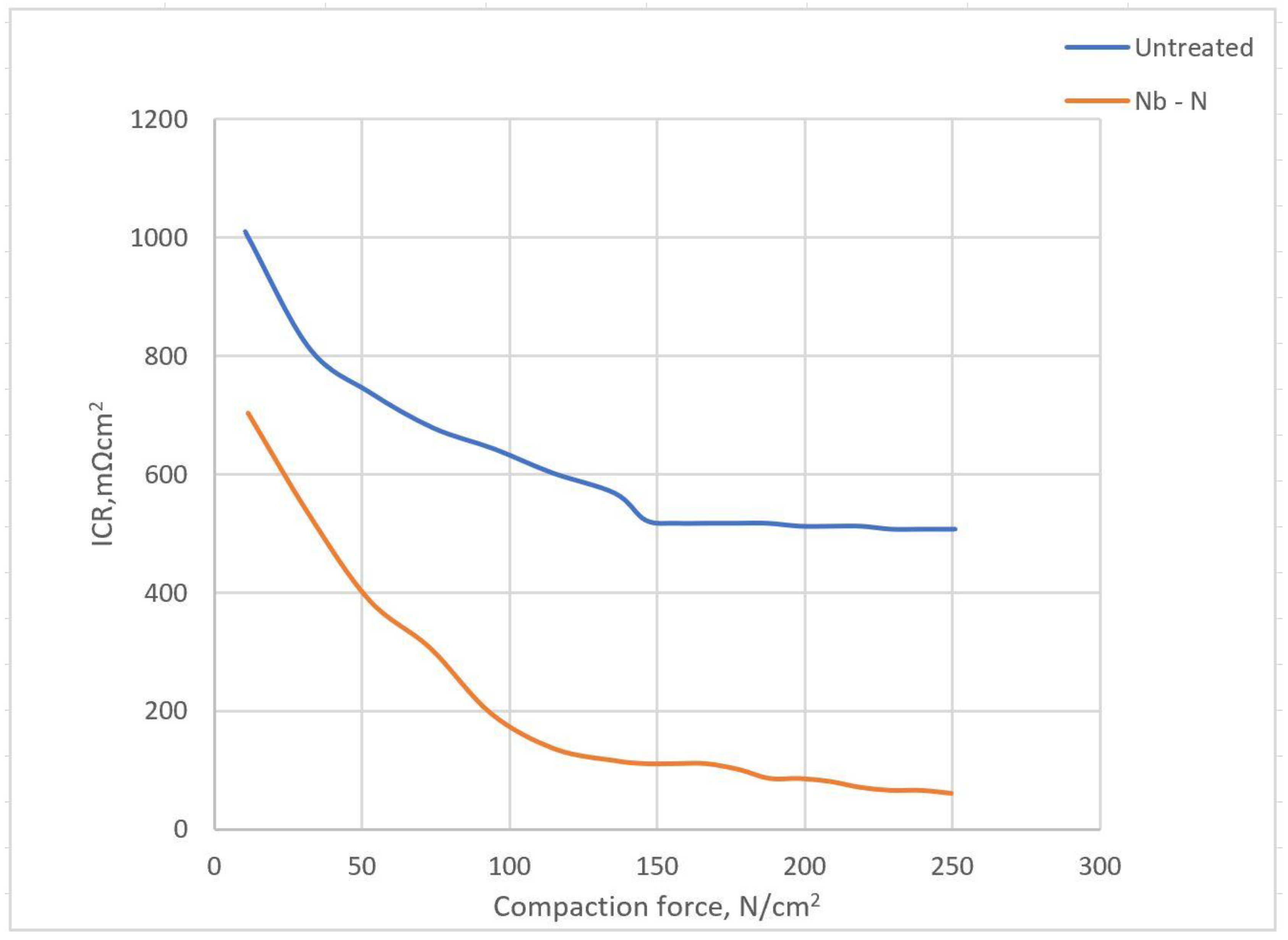
Niobium nitride diffusion (Nb–N layering)Plasma surface diffusion alloying (PSDA)0.05 M H2SO4 + 2 ppm HF at 50 °C[55]
Titanium-nitride (TiN) coatingNot mentioned0.01 M HCl + 0.01 M Na2SO4 solutions[57]
Titanium aluminium nitride (TiAlN)/TiN/CrN layeringElectron beam physical vapour deposition (EBPV)1 M H2SO4 purged with either H2 or O2[58]
Tantalum nitride (TaN) layeringMagnetron sputtering0.05 M H2SO4 + 0.2 ppm HF solution at 80 °C[61]
Tantalum/Tantalum nitride (Ta/TaN)Magnetron sputtering0.5 M H2SO4 + 2 ppm HF solution at room temperature and 80 °C[62]
a-C film layeringCFUBMSIP0.5 M H2SO4 + 2 ppm HF solution at 80 °C[81]
Graphite film layeringNot mentioned0.5 M H2SO4 solution[84]
Ag–polytetrafluoroethylene (PTFE), composite film layeringBi-pulse electroplating method0.5 M H2SO4 + 5 ppm F solution at 80 °C[86]
Carbon polymer composite coatingSpraying and hot-pressing techniques1mM H2SO4 solution at 70 °C[89]
SS304Nickel layeringChemical vapour deposition (CVD)0.5 M H2SO4[50]
Niobium nitride layeringPlasma surface diffusion alloying method0.05 M H2SO4 + 2 ppm F solution at 70 °C[60]
Titanium carbide layeringHEMA technique1 M H2SO4 solution at room temperature[66]
Cr interlayer/a-CDirect current magnetron sputtering0.5 M H2SO4 + 5 ppm HF solution at room temp. and 80 °C[79]
Titanium plateTitanium nitride layeringMIP technique0.5 M H2SO4 + 2 ppm HF solution[56]
Amorphous carbon (a-C) films layeringRF-PECVD methodNot mentioned[80]
Al6061Chromium carbide coatingHVOF thermal spray method0.5 M H2SO4 + 2 ppm HF solution at 70 °C[63]
AISI304Chromium carbide coatingHVOF thermal spray method1 M NaCl solution[64]
AISI 1045Niobium carbide layeringThermo-reactive deposition/diffusion technique (TRD)3 wt.% NaCl solution[69]
AISI441, AISI444, and AISI446Tin(IV) Oxide (SnO2) films layeringChemical vapour deposition (CVD) 1 M H2SO4 + 2 ppm F solution at 70 °C[71]
316L, 317L and 349TMTin(IV) Oxide (SnO2) films layeringChemical vapour deposition (CVD1 M H2SO4 + 2 ppm F solution at 70 °C[72]
Al Graphene oxide layeringPolyvinyl alcohol (PVA)0.5 M H2SO4 solution[74]
Graphene coatingDip coating0.5M NaCl solution[75]
Composite coatingWet spraying0.001 M H2SO4 with 0.1 ppm NaF (pH = 3)[88]
Cu and NiGraphene coatingCVD0.1M NaCl solution[76]
Ni/SSGraphene layeringCVD3.5 wt.% NaCl solution[77]
SS-316L and AA-6061Graphite layeringPVD1 M H2SO4 at 70 °C[85]
Ni open pore metal foamGraphene layeringCVD3 M H2SO4 solution at room temperature, 50 °C and 80 °C[95]
PTFE coatingCoBlast™0.5 M H2SO4 + 2 ppm HF solution at 70 °C
Al open pore metal foamOrganic coatingCataphoretic depositionNaCl solution[96]
Copper and Graphene layeringElectro-deposition1.25 M CuSO4, 0.61 M H2SO4 and Cl-50 ppm solutions[97]
NI-P layeringHypophosphite techniques3.5 wt.% NaCl solution at room temperature[98]

