Design of a High-Performance 16-Slot 8-Pole Electromagnetic Shock Absorber Using a Novel Permanent Magnet Structure


1
Energy and Power Conversion Engineering, University of Science and Technology, Daejeon 34113, Korea
2
Electric Motor Research Center, Korea Electrotechnology Research Institute, Changwon 51543, Korea
*
Author to whom correspondence should be addressed.
Energies 2018, 11(12), 3352; https://doi.org/10.3390/en11123352
Submission received: 15 October 2018
/
Revised: 7 November 2018
/
Accepted: 28 November 2018
/
Published: 30 November 2018
(This article belongs to the Special Issue Electrical Machine Design)
Abstract
:The conventional development of tubular generators for applications intended to harvest energy using vehicle suspension systems is faced with the critical challenge of increasing the power harvested for a given space. Conventional optimal designs of machine dimensions have improved both output power and output power density, but the actual values are still relatively small. Recently, we proposed a novel tubular generator structure that combines a mechanical shock absorber and an electrical generator. An innovative permanent magnet structure using both Halbach array and iron spacers (a hybrid-type) was applied. The high relative permeability of the iron material significantly improved the performance of the proposed generator in comparison with conventional models. A prototype was fabricated and experimentally validated via simulation.
1. Introduction
Better development of energy harvesting technology in electric vehicles is indispensable for saving energy on a global scale, and is also critical for reducing dependence on limited fossil fuels. For many years, regenerative braking technology has been considered and widely commercialized as the major energy recovery application in electric vehicles (EVs). In the next few years, applications for energy harvesting from vehicle suspension systems are likely to become widespread due to their great potential for energy recovery [1]. Based on its working principles and mechanisms, such technology can be classified into electromagnetic (EM) linear harvesting shock absorbers (direct-drive systems) or rotary shock absorbers (indirect-drive systems), which include mechanical transmission and hydraulic transmission [1,2].
Activalve, from the company ClearMotion, is the first commercial product on the market, and uses a hydraulic system to force fluid through a turbine to a generator [3]. Recently, Audi unveiled a new adaptive system called eROT, which generates as much as 613 W on bumpy roads [4,5,6]. This device uses a lever arm to translate linear motion into the rotational motions of gears, and, ultimately, the share, which spins a rotor in an alternator. However, Audi did not confirm when this technology would make its public debut. Similarly, various types of rotary EM shock absorber, using a ball screw mechanism [7,8] or a rack and pinion mechanism, have been developed [9,10]. It is reported that although rotary shock absorbers can regenerate higher power and power density with high sensitivity for the small stroke changes [1,2] their major limitations include their short life cycle, complex configuration, mechanical losses, requirement for extra parts for the ball recirculating system, risk of fluid leakage, etc. Tubular generators are the preferred type of linear shock absorber due to their simple structure, which is easily and reliably integrated into most existing vibration systems without requiring a transmission mechanism [9,11,12,13,14,15,16,17,18]. In addition, they are more applicable to real vehicles, and can be easily fabricated and used as self-powered controllable dampers [1]. One of the main drawbacks to exploiting this area of energy regeneration lies in the difficulty of enhancing output power for a given space. It was proved by Tang et al. [12], Gupta et al. [19], and Duong et al. [13,20,21] that linear EM shock absorbers are either too large to be retrofitted or are unable to provide enough damping force [22]. Ebrahimi et al. [23] and Asadi et al. [24] focused more on damping characteristics than on electrical performance. Therefore, although the damping coefficient varies in a range of 1302–1540 N.s/m, regenerated power is only about 1.5 W. Zuo et al. [11] proposed a half-scale electromagnetic energy harvester for vehicle suspension which could regenerate 16–64 W of output power at a root mean square (RMS) velocity of 0.25–0.5 m/s. However, this regenerated power is much lower than potential harvestable power from a passenger car when it is moving on a class C road (100–400 W) [1,2]. Afterward, Tang et al. [12] optimized the original harvester by proposing a new configuration with higher power density and creating a retrofittable generator. It was expected that about 26 and 33 W of power, respectively, could be practically harvested using the single-layer and double-layer linear electromagnetic transducers. By employing the Halbach array for the permanent magnets (PMs) and double-layered PMs, output power and power density were enhanced by 5 times and 8 times, respectively. However, because it was a coreless model (i.e., it employed a non-magnetic material for the winding slots), this model had an excessive electrical air gap that limited flux density in the coil winding.
Interestingly, most conventional studies have focused on replacing a mechanical shock absorber with an electrical one. There are only a few publications discussing the combination of both parts [13,20,21,24]. This configuration can be defined as a semi-active, or passive, suspension, and it introduces different difficulties and design considerations, which have seldom been mentioned in the past. In this paper, a novel tubular generator is proposed and investigated as a candidate for energy harvesting from the motion in vehicle suspension systems. In contrast to previous studies, a novel topology was designed to combine a mechanical shock absorber with an electric generator. The design targets include maximum and average powers of 180 and 75 W, respectively, and maximum and average power densities of 0.180 and 0.075 W/cm3, respectively. To achieve these targets, a number of innovations were made, which are reported in this paper. First, the winding slots of the proposed generator were made of an iron material (this design is called a cored model). Second, a classical Halbach array was modified by inserting iron spacers. Because of its high relative permeability, the output power was significantly increased. Moreover, the 4 mm mechanical air gap reported in previous research [13,20,21] was decreased to only 0.7 mm by using two thin layers of carbon fiber for the PM cover. Although these innovations could significantly increase machine performance, interactions between the PMs and the iron core also result in high electromagnetic force, which causes negative effects on ride comfort and safety.
2D and 3D finite element analyses (FEAs) using Altair (Flux 2D/3D software) were performed to review the magnetic design and to provide analytical prediction of performance. The performance evaluation was also used to establish the validity of the analysis.
2. Description of the Proposed Machine
Figure 1 and Figure 2 schematically show the geometry of a commercial shock absorber and of a generator with the same general dimensions. As mentioned in the previous section, to assemble the new device for use in a mechanical suspension system, PMs were located within the inner frame of the shock absorber, and the windings were wound and attached to the outer frame. Based on the dimensions of a commercial shock absorber used in Korando cars (a type of SUV), the inner diameter of the proposed generator was fixed at 40 mm, while the outer diameter and total length were adjusted as necessary.
In a previous study [13,20,21], the outer diameter of the device varied from 80 to 160 mm, and the maximum length of the machine was about 260 mm. In the current work, the outer diameter was roughly 110 mm. The slot–pole combination was very similar to that of the previous single-layer models [11,13], which had sixteen slots with eight poles. However, one additional pole was inserted, so there were a total of nine poles in the proposed machine. If one pole pitch is 27 mm, the total length of the machine is 243 mm. Over two pole pitches, there are four coil sets. The relative positions of the coil winding and excited flux are shown in Figure 3. For simplification and cost-effectiveness of the drive system, the coil windings were serially connected to create a two-phase generator [9,11,12,13]. It can clearly be seen in Figure 2 that the flux density was mostly distributed on Coils 1 and 3, but with different signs. This phenomenon leads to unbalanced power distribution in different phases. It should be noted that, owing to the specific vibrating motion, the voltage and current waveform of the traditional three-phase machine can be distorted. For example, Ebrahimi et al. [25] presented experimental data for a three-phase machine, in which the voltage waveform of each phase was totally distorted. To get a smoother waveform for electronic drive systems, one- or two-phase systems are preferable.
To protect the PMs, two layers of carbon fiber were employed instead of stainless steel. Because the thickness of these layers was only 0.1 mm and the mechanical air gap was 0.5 mm, the magnetic air gap was only 0.7 mm. Note that the material of the inner iron layer was stainless steel. Although using a magnetic material would increase the performance of the machine, there are difficulties in the assembly process due to the resulting magnetic force.
3. FEM Analysis
3.1. Specifications of the Proposed Machine
This section deals with 2D FEA, which theoretically describes the characteristics of the proposed topology. For the rated state analysis, the ideal initial position of the moving part was set up as shown in Figure 2. In the initial alignment position, winding slots directly faced the spacers.
When actually driving, depending on the road surfaces and vehicle speed, operating conditions in a shock absorber are arbitrary. From previous studies [9,11,12,13], it was determined that when a medium-size car is traveling on a class C road at a speed of 60 mph, the shock absorber vibrating speed and peak-to-peak stroke length would be 0.25 m/s and 11.25 mm, respectively. These conditions were considered the rated operating conditions for both simulations and experiments. The major design specifications of the device with the proposed topology are summarized in Table 1.
3.2. Novel Hybrid Permanent Magnet Structure
To enhance performance in terms of power and power density, a novel hybrid permanent magnet structure was created. As illustrated in Figure 3, iron spacers were inserted in a Halbach array and directly faced the coil slots, in their initial alignment positions. Only the thickness of the radial PMs was modified, and all other parameters remained the same.
As shown in Figure 4, the maximum regenerated powers from the novel hybrid-type PM model and from the classical Halbach array model were 293.9 and 184.0 W, respectively. Although the total volume of the machines was the same, the output power of the novel hybrid-type PM model was significantly greater (59.7%). Moreover, the novel configuration would reduce the amount of PM needed, which is the most expensive material when manufacturing a prototype.
3.3. Induced Voltage
The back EMF and induced voltage in the different phases are compared in Figure 5. These show that under the same operating conditions, both peak and RMS values of the no-load back EMF were twice the induced voltage on the same phase. This phenomenon is explainable by the external circuit setup, by which the load resistance is matched with the resistance of the coil windings. Moreover, as explained in Section 2, the unbalanced flux distribution on the coil windings resulted in unbalanced voltage in each phase.
Another noticeable characteristic is the difference in frequency in each phase of the proposed generator. The voltage on Coil 1, or the 0° coil, was represented by [9,11,12]:
and a 90° coil doubles the frequency wave:
where B0, L, and vmax denote the magnetic field intensity of the coil in the radial direction, length of the windings, and maximum vibrating speed, respectively. It can clearly be seen from Figure 6 that the frequencies in Phase 1 and Phase 2 were 10 and 20 Hz, respectively.
3.4. Output Power and Electromagnetic Force
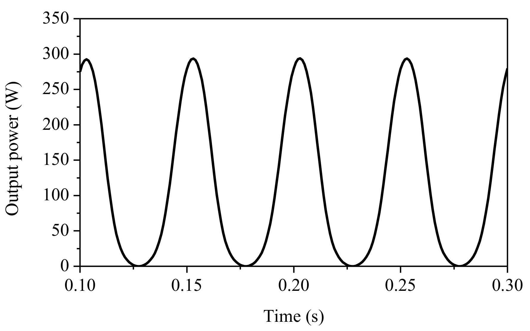
The output power under the rated conditions is shown in Figure 6. Because of the spacers and iron teeth, the power waveform was slightly sharp. Analyzed results show that the maximum and average harvested powers were 293.9 and 115.2 W, respectively. These values exceeded the original design targets.
Figure 7 shows the power variation for different vibrating speeds. Although the proposed cored-model and the coreless model have different geometries, the output powers of both are proportional to the square of the vibration speed [9,11,12,13,20,21]. For example, when the vibrating speed was 0.100 m/s, the maximum power was 48.26 W. Thus, the maximum power at 0.150 m/s could be estimated by:
Similar trends were obtained at different vibrating speeds and were consistent with the conventional study of the coreless models [11,13].
The major shortcomings of the proposed machine are its high cogging force and magnetic force, which cause negative effects on safety and driving comfort. According to manufacturer recommendations, if installing a generator with a shock absorber in an SUV car, the maximum value of the cogging force should be ≤2000 N. However, the maximum cogging force and magnetic force of this device were 2380.4 and 2789.6 N, respectively (Figure 8).
4. Experimental Setup
4.1. Experimental Setup
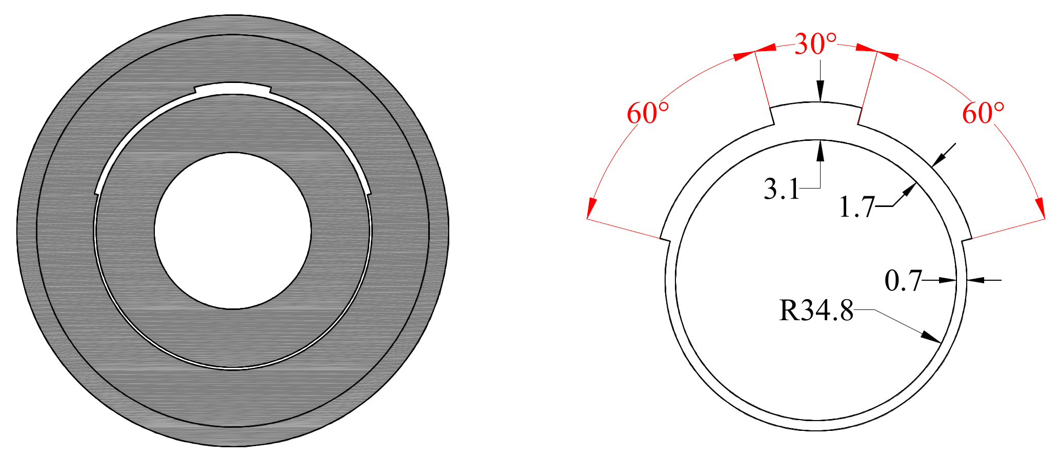
Figure 9 shows the different components of the prototype, including the PM ring and its black carbon cover, an outer core with iron teeth, and the back yoke. On the inner circumference of the winding path, the iron teeth were beveled into three cutting curves with different thicknesses and opening angles, as shown in Figure 10.
In the prototype, there were two cutting curves with 60° opening angles and one cutting curve with a 30° opening angle. Because each of the cutting teeth had a different thickness, the magnetic air gap lengths were different (0.7, 1.7, and 3.1 mm). This configuration led to an air gap that was not uniform, which made it impossible to model in the 2D FEA analysis. To simplify the situation for 2D FEA analysis, an inner equivalent air gap was proposed using the following equation:
Note that when the inner magnetic air gap was increased from 0.7 to 1.23 mm, the thickness of the iron teeth was decreased from 14.5 to 13.97 mm. The other design parameters were not changed. To validate the analysis using experimental data, 2D FEA analyses were performed using the equivalent air gap, and 3D FEA analyses were performed using the same non-uniform air gap.
4.2. Equivalent Stroke Length
Figure 11 shows the experimental setup. To generate a vibrating motion, a servo motor was connected to the moving part of the machine by a shaft. When the vibrating speed was 0.25 m/s, and peak-to-peak stroke length was 11.25 mm, rotating speed of the servo motor was 3000 rpm. Unfortunately, this speed exceeded the threshold of the servo motor.
To solve this problem, an equivalent peak-to-peak stroke length was considered. From the following equation:
when the RMS vibrating speed was 0.25 m/s, and the peak-to-peak stroke length was modified to 12.0 mm, the estimated vibration frequency was 9.38 Hz. Therefore, the rotation speed of the servo motor was reduced to 2813.5 rpm. The output power values for different stroke lengths are listed in Table 2. Within a limited margin for stroke length, output power was similar.
5. Validation by Experiment
5.1. Induced Voltage
Comparison of the results from 2D FEA simulations and experiments of the RMS induced voltage in Phases 1 and 2 (under full load conditions) for different vibrating speeds is shown in Figure 12. Similar trends could be seen in the 2D simulation and experimental results, and the average deviation for each phase was 5.6% and 10.8%, respectively. Although the deviation was up to 10.8% in Phase 2, it was still acceptable because of the equivalent air gap.
Owing to the imbalance in the flux distribution between different phases, the voltages induced in Phase 1 and Phase 2 were totally different in both value and frequency. Contrary to expectations, the voltages measured in Phase 2 were higher than in the analyzed data. It is very likely that the lower flux linkage in this phase, and noise when operating the machine, led to these differences. A noticeable phenomenon is the linear proportionality between voltage and vibrating speed, which was discussed in previous publications [11]. In addition, as mentioned in Section 3, at the same vibrating speed, the back EMF value in the same phase was double that of the induced voltage, due to the external circuit setup. For example, when the vibrating speed was 0.25 m/s, the RMS back EMF in Phase 1 was approximately 75.9 V, while the induced voltage was around 38.6 V.
5.2. Output Power and Power Density
Figure 13a shows the side view of the 3D model. In this 3D model, all dimensions were modified to be the same as the prototype, particularly the non-uniform air gaps. Figure 13b shows the flux density distribution at a vibrating speed of 0.25 m/s.
Comparison of the output power for different vibrating speeds is shown in Figure 14, and a summary of all data is presented in Table 3. In terms of maximum power, the average deviations of the 2D and 3D analyses were 9.3% and 3.7%, respectively. In the case of average power, the average deviations of the 2D and 3D analyses were higher (15.9% and 10.2%). These differences can be explained in part by the non-uniform air gap and saturation phenomenon of the iron core.
When the vibrating speed was 0.25 m/s, measured maximum and average powers were 225.0 and 83.1 W, respectively, both of which exceeded the initial design targets.
In contrast to the results from the study in [12], in which power density was calculated over the total volume of the machine, in this paper, the volume of the inner mechanical part was neglected. The volume considered was calculated for the active part, including iron teeth, pure copper, air gap, inner iron layer, PMs, and iron spacers.
The measured active volume of the prototype was taken from the 3D drawing file for the prototype provided by the manufacturer, and was about 1828.37 cm3. Therefore, the measured maximum and average power densities under the rated conditions were approximately 0.123 and 0.045 W/cm3, respectively. Although the average power density was higher than the previous model by nearly 40% [12], these values cannot yet achieve the design targets.
6. Conclusions
For this paper, an electromagnetic shock absorber with a cored-type tubular generator with a novel combination of classical Halbach array and iron spacers was proposed and investigated. This configuration significantly improved power by around 59.7% while the active volume remained similar. A prototype was fabricated and experimentally verified using 2D and 3D FEA analyses for various vibrating speeds. Due to limitations of the experimental facilities and manufacturing technology, equivalent peak-to-peak stroke lengths and equivalent air gaps were introduced. The simulation results obtained in the 2D and 3D FEA were examined and confirmed by corresponding experiments with acceptable agreement. Under the rated conditions with 0.25 m/s vibrating speed, the maximum and average powers were 225.0 and 83.1 W, respectively. Although the output power was satisfactory, it was not possible to achieve the power density design targets. The major obstacle is the large magnetic force. However, this could be acceptable in a heavy vehicle, such as a passenger bus or truck.
In a further study, a different slot–pole combination will be considered to continue improving the power density, and to eliminate the unbalanced power distribution in each phase. Moreover, it is necessary to apply an optimization algorithm to determine the trade-off between the power produced and the magnetic force.
Author Contributions
Conceptualization, Y.-D.C.; Software, M.-T.D., Validation; M.-T.D., Writing, M.-T.D.; Supervision, Y.-D.C.; Administration, D.-K.H.
Funding
This work was supported by the Ministry of Trade, Industry and Energy, Sejong, South Korea, through the Industrial Technology Innovation Program “Development of Electric Compressor to Improve Low End Torque Performance and Transient Performance of 1.6L Grade Small Diesel Engine” under Grant 10062541.
Conflicts of Interest
The authors declare no conflict of interest.
References
- Abdelkareem, M.A.A.; Xu, L.; Ali, M.K.A.; Elagouz, A.; Mi, J.; Guo, S.; Liu, Y.; Zuo, L. Vibration energy harvesting in automotive suspension system: A detailed review. Appl. Energy 2018, 229, 672–699. [Google Scholar] [CrossRef]
- Zhang, R.; Wang, X.; John, S. A Comprehensive Review of the Techniques on Regenerative Shock Absorber Systems. Energies 2018, 11, 1167. [Google Scholar] [CrossRef]
- ClearMotion—Technology. Available online: http://www.clearmotion.com/technology (accessed on 7 June 2018).
- DPCcars New 2018 Audi A8 Active Suspension. Available online: https://www.youtube.com/watch?v=P7QQLxthHyQ (accessed on 29 November 2018).
- Here’s How Audi’s New Technology Harnesses Suspension Movement to Boost MPG. Available online: https://jalopnik.com/heres-how-audis-new-technology-harnesses-suspension-mov-1785122614 (accessed on 6 November 2018).
- Audi unveils suspension-energy regeneration technology. Available online: https://www.motorauthority.com/news/1092944_audi-unveils-suspension-energy-regeneration-technology (accessed on 6 November 2018).
- Experimental verification of energy-regenerative feasibility for an automotive electrical suspension system-IEEE Conference Publication. Available online: https://ieeexplore.ieee.org/document/4456407 (accessed on 6 November 2018).
- Cassidy, I.L.; Scruggs, J.T.; Behrens, S.; Gavin, H.P. Design and experimental characterization of an electromechanical transducer for large-scale vibratory energy harvesting applications. J. Intell. Mater. Syst. Stuct. 2011. [Google Scholar] [CrossRef]
- Zhang, P.S. Design of Electromagnetic Shock Absorbers for Energy Harvesting for Energy Harvesting from Vehicle Suspensions. Master Thesis, Stony Brook University, Stony Brook, NY, USA, 2010. [Google Scholar]
- Li, Z.; Zuo, L.; Luhrs, G.; Lin, L.; Qin, Y. Electromagnetic Energy-Harvesting Shock Absorbers: Design, Modeling, and Road Tests. IEEE Trans. Veh. Technol. 2013, 62, 1065–1074. [Google Scholar] [CrossRef]
- Zuo, L.; Scully, B.; Shestani, J.; Zhou, Y. Design and characterization of an electromagnetic energy harvester for vehicle suspensions. Smart Mater. Struct. 2010, 19, 045003. [Google Scholar] [CrossRef]
- Tang, X.; Lin, T.; Zuo, L. Design and Optimization of a Tubular Linear Electromagnetic Vibration Energy Harvester. IEEE/ASME Trans. Mechatron. 2014, 19, 615–622. [Google Scholar] [CrossRef]
- Duong, M.T.; Chun, Y.D.; Han, P.W.; Park, B.G.; Bang, D.J.; Lee, J.K. Design of An Electromagnetic Energy Harvesting System Applied to The Shock Absorber of A Sport Utility Vehicle. Available online: http://www.dbpia.co.kr (accessed on 4 June 2018).
- Gysen, B.L.J.; Paulides, J.J.H.; Janssen, J.L.G.; Lomonova, E.A. Active Electromagnetic Suspension System for Improved Vehicle Dynamics. IEEE Trans. Veh. Technol. 2010, 59, 1156–1163. [Google Scholar] [CrossRef] [Green Version]
- Ebrahimi, B.; Khamesee, M.B.; Golnaraghi, M.F. Feasibility study of an electromagnetic shock absorber with position sensing capability. In Proceedings of the 2008 34th Annual Conference of IEEE Industrial Electronics, Orlando, FL, USA, 10–13 November 2008. [Google Scholar]
- Goldner, R.B.; Zerigian, P. Electromagnetic linear generator and shock absorber 2005. Available online: https://patents.google.com/patent/US6952060B2/en (accessed on 29 November 2018).
- Zuo, L.; Tang, X.; Zhang, P.S. Electricity generating shock absorbers 2013. Available online: https://patents.google.com/patent/US20130127175A1/en (accessed on 29 November 2018).
- Li, P.; Zuo, L.; Lu, J.; Xu, L. Electromagnetic regenerative suspension system for ground vehicles. In Proceedings of the 2014 IEEE International Conference on Systems, Man, and Cybernetics (SMC), San Diego, CA, USA, 5–8 October 2014. [Google Scholar]
- Gupta, D.A.; Mulcahy, D.T.M.; Hull, D.J.R. Electromagnetic Shock Absorbers. 4. Available online: https://pdfs.semanticscholar.org/f1f1/ef251e2435cd0ea230eed520544c662edd2e.pdf (accessed on 30 November 2018).
- Duong, M.-T.; Chun, Y.-D. Design of an Electromagnetic Energy Harvesting System Applied to Shock Absorber in Sport Utility Vehicle. J. Magn. 2018, 23, 392–398. [Google Scholar] [CrossRef]
- Duong, M.-T.; Chun, Y.-D.; Bang, D.-J. Improvement of Tubular Permanent Magnet Machine Performance Using Dual-Segment Halbach Array. Energies 2018, 11, 3132. [Google Scholar] [CrossRef]
- Guo, S.; Xu, L.; Liu, Y.; Guo, X.; Zuo, L. Modeling and Experiments of a Hydraulic Electromagnetic Energy-Harvesting Shock Absorber. IEEE/ASME Trans. Mechatron. 2017, 22, 2684–2694. [Google Scholar] [CrossRef]
- Ebrahimi, B.; Khamesee, M.B.; Golnaraghi, F. Eddy current damper feasibility in automobile suspension: modeling, simulation and testing. Smart Mater. Struct. 2009, 18, 015017. [Google Scholar] [CrossRef]
- Asadi, E.; Ribeiro, R.; Khamesee, M.B.; Khajepour, A. Analysis, Prototyping, and Experimental Characterization of an Adaptive Hybrid Electromagnetic Damper for Automotive Suspension Systems. IEEE Trans. Veh. Technol. 2017, 66, 3703–3713. [Google Scholar] [CrossRef]
- Ebrahimi, B. Development of Hybrid Electromagnetic Dampers for Vehicle Suspension Systems. 192. Available online: https://uwspace.uwaterloo.ca/handle/10012/4375 (accessed on 29 November 2018).
Figure 1.
(a) Actual dimensions of a commercial shock absorber; (b) shock absorber with additional electrical components.
Figure 1.
(a) Actual dimensions of a commercial shock absorber; (b) shock absorber with additional electrical components.

Figure 2.
(a) Half cross section of the proposed machine; (b) Relative position between winding slots and excited flux density.
Figure 2.
(a) Half cross section of the proposed machine; (b) Relative position between winding slots and excited flux density.

Figure 3.
Tubular generator with (a) classical Halbach array; (b) Novel hybrid-type.

Figure 4.
Comparison of power output from the Halbach array and new hybrid configuration.

Figure 5.
Back EMF and induced voltage in: (a) Phase 1; (b) Phase 2.

Figure 6.
Output power under the rated condition.

Figure 7.
Output power for different vibrating speeds.

Figure 8.
Cogging force and electromagnetic force.

Figure 9.
Prototype.
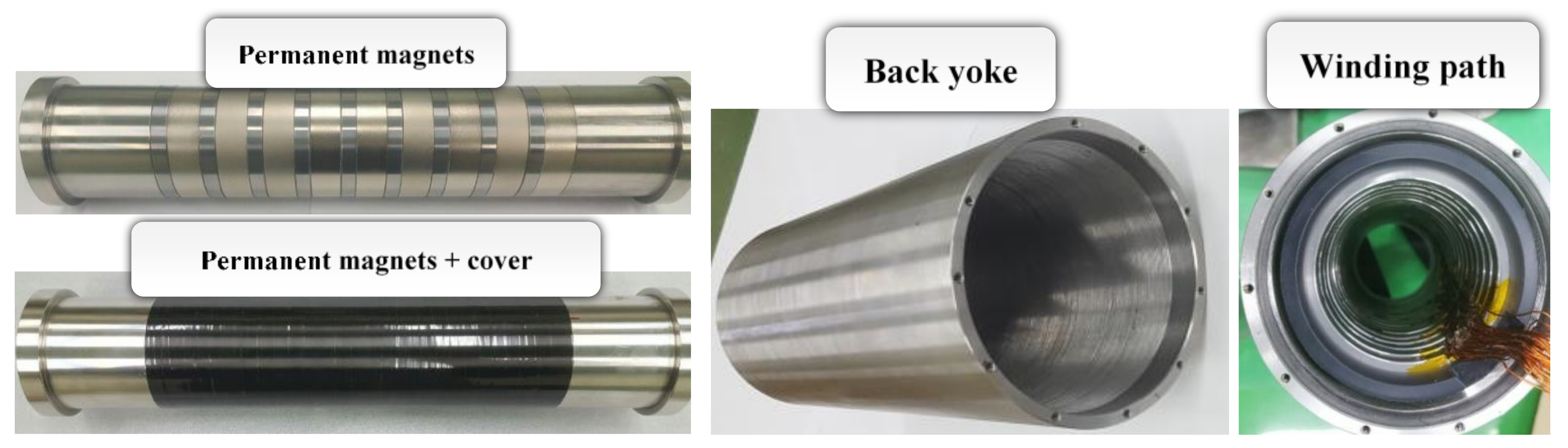
Figure 10.
Side view of the cutting teeth.

Figure 11.
Layout of the test bench.

Figure 12.
Root mean square (RMS) induced voltage in: (a) Phase 1; (b) Phase 2.

Figure 13.
(a) Side view of the 3D finite element analysis (FEA) model; (b) Flux distribution at a vibrating speed of 0.25 m/s.
Figure 13.
(a) Side view of the 3D finite element analysis (FEA) model; (b) Flux distribution at a vibrating speed of 0.25 m/s.

Figure 14.
(a) Maximum output power; (b) Average output power.


Table 1.
Specifications of the proposed machine.
| Item | Value | Unit |
|---|---|---|
| Outer diameter | 110 | mm |
| Axial length | 243 | mm |
| Inner diameter | 40 | mm |
| Magnetic air gap | 0.7 | mm |
| Inner iron thickness | 2.4 | mm |
| Radial PM thickness | 4.2 | mm |
| Axial PM thickness | 12.4 | mm |
| Spacer thickness | 8.2 | mm |
| Pole pitch | 27 | mm |
| Radial PM width | 18 | mm |
| Axial PM width | 9 | mm |
| Tooth thickness | 14.5 | mm |
| Tooth width | 8.5 | mm |
| Number of turns per slot | 114 | turns |
| Back iron thickness | 5 | mm |
| Radial PM material | NdFeB, = 1.26 T, = 1.05 at 20 °C | --- |
| Axial PM material | NdFeB, = 1.40 T, = 1.05 at 20 °C | --- |
| Core material | S20C | --- |
| Inner iron material | Stainless steel | --- |
Table 2.
Output power with different equivalent stroke lengths.
| Stroke Length(p-p) (mm) | Maximum Power (W) | Average Power (W) |
|---|---|---|
| 10.0 | 259.0 | 108.5 |
| 11.25 | 259.6 | 103.2 |
| 12.0 | 260.1 | 100.2 |
Table 3.
Comparison of the output power for different vibrating speeds.
| Vibrating Speed (m/s) | Maximum Power (W) | Average Power (W) | ||||
|---|---|---|---|---|---|---|
| 2D | 3D | Exp. | 2D | 3D | Exp. | |
| 0.100 | 42.8 | 40.3 | 39.4 | 16.3 | 15.3 | 14.3 |
| 0.125 | 66.7 | 62.4 | 60.5 | 25.4 | 23.7 | 21.3 |
| 0.150 | 95.7 | 89.7 | 91.0 | 36.5 | 34.2 | 31.0 |
| 0.175 | 129.5 | 121.2 | 120.1 | 49.4 | 46.2 | 40.4 |
| 0.200 | 168.4 | 157.5 | 148.7 | 64.3 | 60.2 | 54.8 |
| 0.225 | 212.0 | 198.5 | 189.7 | 80.9 | 75.8 | 66.0 |
| 0.250 | 260.1 | 243.7 | 225.0 | 100.1 | 93.9 | 83.1 |
© 2018 by the authors. Licensee MDPI, Basel, Switzerland. This article is an open access article distributed under the terms and conditions of the Creative Commons Attribution (CC BY) license (http://creativecommons.org/licenses/by/4.0/).
Share and Cite
MDPI and ACS Style
Duong, M.-T.; Chun, Y.-D.; Hong, D.-K. Design of a High-Performance 16-Slot 8-Pole Electromagnetic Shock Absorber Using a Novel Permanent Magnet Structure. Energies 2018, 11, 3352. https://doi.org/10.3390/en11123352
AMA Style
Duong M-T, Chun Y-D, Hong D-K. Design of a High-Performance 16-Slot 8-Pole Electromagnetic Shock Absorber Using a Novel Permanent Magnet Structure. Energies. 2018; 11(12):3352. https://doi.org/10.3390/en11123352
Chicago/Turabian StyleDuong, Minh-Trung, Yon-Do Chun, and Do-Kwan Hong. 2018. "Design of a High-Performance 16-Slot 8-Pole Electromagnetic Shock Absorber Using a Novel Permanent Magnet Structure" Energies 11, no. 12: 3352. https://doi.org/10.3390/en11123352
Note that from the first issue of 2016, this journal uses article numbers instead of page numbers. See further details here.