Article

Numerical Analysis of Longitudinal Residual Stresses and Deflections in a T-joint Welded Structure Using a Local Preheating Technique

1
Bestprojekt, Bureau of Energetics and Mechanical Engineering Ltd., Petrovaradinska 7, 10000 Zagreb, Croatia
2
Faculty of Mechanical Engineering and Naval Architecture, University of Zagreb, I. Lučića 5, 10000 Zagreb, Croatia
3
LTEF—Laboratory for Thermodynamics and Energy Efficiency, Faculty of Electrical Engineering, Mechanical Engineering and Naval Architecture, University of Split, Rudjera Boskovića 32, 21 000 Split, Croatia
*
Author to whom correspondence should be addressed.
Energies 2018, 11(12), 3487; https://doi.org/10.3390/en11123487
Submission received: 16 November 2018 / Revised: 3 December 2018 / Accepted: 11 December 2018 / Published: 14 December 2018

Abstract

:
In this paper a numerical analysis of a T-joint fillet weld is performed to investigate the influences of different preheat temperatures and the interpass time on the longitudinal residual stress fields and structure deflections. In the frame of the numerical investigations, two thermo-mechanical finite element models, denoted M2 and M3, were analyzed and the results obtained were then compared with the model M1, where the preheating technique was not applied. It is concluded that by applying the preheat temperature prior to the start of welding the post-welding deformations of welded structures can be significantly reduced. The increase of the preheat temperature increased the longitudinal residual stress field at the ends of the plates. The influence of the interpass time between two weld passes on the longitudinal residual stress state and plate deflection was investigated on two preheated numerical models, M4 and M5, with an interpass time of 60 s and 120 s, respectively. The results obtained were then compared with the preheated model M3, where there was no time gap between the two weld passes. It can be concluded that with the increase of interpass time, the plate deflections significantly increase, while the influence of the interpass time on the longitudinal residual stress field can be neglected.

1. Introduction

The welding technique is one of the most frequently used engineering methods of joining structural components in many industrial fields. The large localized heat generation during welding and subsequent very fast cooling of the melted material to ambient temperature have, as a consequence, the occurrence of permanent residual stresses and dimensional imperfections in the welded structure. Such imperfections can cause large inconveniences during the structure assembly, while high residual stresses can have a detrimental impact on its integrity and durability [1,2,3,4]. The elimination of these consequences using conventional post-weld thermal or mechanical treatments requires an extended production time and incurs additional financial expenses. For these reasons, it is highly desirable to carry out measures that will lessen these consequences prior to, or during, the welding process. To mitigate the residual stress and plate deflections in a single pass T-joint fillet weld Gannon et al. [5] and Fu et al. [6] numerically and experimentally studied the influence of various welding sequences on the residual stress field. It was concluded that the welding sequence has a negligible impact on the residual stress distribution pattern, but has an influence on the longitudinal stress peaks. Jiang and Yahiaoui [7] presented a three-dimensional thermomechanical model to investigate the effect of welding sequences on the residual stress field in a multipass welded piping branch junction. Li et al. [8] dealt with water cooling effects on welding residual stresses in a core shroud. In their contribution, Moat et al. [9] concluded that martensitic filler metals with low transformation temperatures can efficiently reduce the welding residual stresses. Cozzolino et al. [10] investigated the mitigation of residual stresses and distortions using a post-weld rolling technique. Schenk et al. [11] studied the influence of different clamping conditions in a T-joint fillet welded structure. Chuvas et al. [12] investigated welding residual stress relief with mechanical vibrations using the X-ray diffraction technique and Monte Carlo method on a butt-welded model of two plates. A significant longitudinal residual stress reduction of 40% was observed after the application of mechanical vibration procedures, while in the transversal direction, the residual stress was reduced by 20%. A finite element model with a clearer insight into the influential parameters of the vibration stress treatment was presented by Yang [13]. In this study, the impact of frequency, vibration amplitude and welding parameters on the residual stress were investigated for resonant and non-resonant cases. Samardžić et al. [14] experimentally elaborated the influence of vibrations on the residual stress in a T-joint fillet weld structure and concluded that this method can reduce the residual stresses in specific areas of the structure, depending on the position of the force inductor. Dong et al. [15] suggested a simple engineering scheme for estimating residual stress reduction that is based on post-weld heat treatment temperature, material type and component wall thickness. Fu et al. [16] investigated the structure deflections under a constant preheat temperature during the welding process in a T-joint welded structure. They concluded that the preheating during the welding has a significant effect on structure deformations, while its influence on the longitudinal and tensile residual stresses is much smaller. In their numerical study, Kala et al. [17] investigated the influence of the interpass time between various sequences in multipass butt-welded steel plates. They concluded that the interpass time has a significant effect on the structure deformations. Moreover, they concluded that the interpass time has a large influence on the phase-transformations in weldment. Ilman et al. [18] carried out an investigation to mitigate the residual stresses in butt-welded plates using static thermal tensioning to improve the fatigue performance of the welded structure. Zhang et al. [19] introduced a multi-beam preheating method to reduce structure deformation. They concluded that a multi-beam preheating method can successfully reduce the compressive stress in the welding area. In their study, Okano and Mochizuki [20] applied a trailing heat sink using a water-cooling device. They reduced the longitudinal tensile zone width, longitudinal bending and angular deformations by up to 70%. Meanwhile, the tensile longitudinal stresses in the weld area were negligibly reduced by the heat sink usage in this case. Zubairuddin et al. [21] numerically and experimentally investigated butt-welded plates during a GTA welding process and concluded that the preheating procedure before welding can significantly reduce welding distortions.
As can be seen above, there are numerous mitigation techniques that can be undertaken before or during the welding process to reduce residual stresses and structure deformations. It is important to note that the mitigation techniques mentioned above are primarily suitable for indoor factory fabrication when structures are of smaller dimensions. In this work, a study of the influence of local preheat temperature and the interpass time on the longitudinal residual stress field and deformations was carried out on a T-joint fillet welded structure, in the case where the preheat temperature was kept constant only at the beginning of the welding process. This technique is more appropriate for outdoor on-site welding of large structures.
The paper consists of six sections: In Section 1 a survey of the literature is given; in Section 2, the geometry of a T-joint fillet welded model, the welding parameters and the preheat temperature volume are defined; a detailed description of the numerical model is provided in Section 3; in Section 4 the data about the application of the preheat temperature and interpass time to the numerical models are provided; Section 5 contains an analysis of the preheat temperature influence and interpass time on the residual stress fields and deflections of the T-joint fillet welded model; in the last section, the conclusions of the investigations are summarized.

2. T-joint Fillet Weld Geometry and Welding Conditions

To analyze the influence of the preheat temperature and the interpass time between two weld passes on the longitudinal residual stress (residual stress in welding direction) field and plate deflection, a T-joint fillet weld model taken from Deng et al. [22] was considered. The plates were joined with two single pass welds using the MAG procedure without any time gap in between and their geometry is shown in Figure 1. The welding conditions are given in Table 1. The plate material was SM400A carbon steel, for which the temperature-dependent thermal and mechanical properties are shown in Figure 2 and Figure 3, and the elemental composition is given in Table 2.
Since only the experimental measurements of horizontal plate deflections, using a Vernier caliper, are provided in Reference [22], the validation of longitudinal residual stresses was performed using two idealized solutions from the literature [23], which could provide acceptable engineering results for single-pass T-joint structures welded with MAG technology [5,24,25], and are appropriate for the evaluation of the reference model M1 (Table 3). In these two simple solutions it is assumed that the maximum residual stress along the line A-B in the middle plane of the horizontal plate (Figure 4) is tensile and that it reaches the yield stress of the material. The compressive residual stress along the same line governs the rest of the horizontal plate and can be calculated as follows:
σ c = 2 b t b 2 b t   [ MPa ]
or
σ c = 2 b t + t p σ y + b s t w σ y ( b 2 b t ) t p + A s + b s t w   [ MPa ]
where
b t = t w 2 + 0.26 Δ Q t w + 2 t p   [ mm ]
b s = t w t p ( b t t w 2 )   [ mm ]
Δ Q = 78.8 l 2
l = 0.7 t w   when   t <   10   mm
l = 7.0   when   t   10   mm
In the equations given above, b is the width of the horizontal plate in mm, tw and tp denote the thicknesses of the horizontal and vertical plates in mm, 2bt is the tensile zone width of the horizontal plate, bs is the tensile zone width of the vertical plate, σy is the yield stress of the material at room temperature, while As is the cross section of the vertical plate in mm2.

3. Numerical Model

A numerical simulation was performed employing a sequentially coupled thermal-elastic-plastic model [26,27,28,29]. In this case, the welding simulation process consisted of two separate numerical analyses, i.e., one thermal and one mechanical. In the thermal analysis, the key equation for nonlinear transient heat transfer can be written in the form of:
x ( k x T x ) + y ( k y T y ) + z ( k y T z ) + Q = ρ C T t
In Equation (8) kx, ky, and kz are the thermal conductivity components in the x, y and z directions; T is the body temperature; Q is the generated heat input; ρ is the material density; C is the specific heat capacity of the material; and t is time, respectively. A general solution for Equation (8) can be obtained when the following initial boundary conditions on the outer model surfaces are taken into account:
T ( x , y , z , 0 ) = T 0 ( x , y , z )
( k x T x N x + k y T y N y + k z T z N z ) + q s + h c ( T T ) + h r ( T T r ) = 0
where Nx, Ny, and Nz are the direction cosine of the normal to the boundary; hc denotes the convective heat transfer coefficient; hr is the radiation heat transfer coefficient; qs represents the heat flux on the outer body boundaries; Tr denotes the radiation temperature; and T is the ambient temperature. Heat loss due to radiation can be expressed by the following expression:
h r = σ B o l t ε s u r f F ( T 2 + T r 2 ) ( T + T r )
where σBolt = 5.67 × 10⁻⁸ Wm−2K−4 denotes the Stefan–Boltzmann constant; εsurf is the surface emissivity factor; and F is the configuration factor. The generated heat input applied to the weld volume can be expressed as follows:
Q = η U I V H
In Equation (12) η represents the efficiency of the welding process, I is the welding current, U denotes the arc voltage, and VH is the weld volume. Although it is usual in the literature for the temperature distribution calculation in the MAG welding process to be performed as a combination of Gaussian and a uniformly distributed volumetric heat flux model [5,22], in this study, a pure volumetric heat flux with uniformly distributed heat input was used to speed up the simulation process, Q = 5.22 × 10¹⁰ Jm−3s−1 per weld volume was applied and its value was obtained from Equation (12). The MAG welding process efficiency η = 80% was taken according to the EN 1011-1 [30]. On the model boundaries, the convection heat transfer coefficient hc = 10 Wm−2K−1 and the surface emissivity εsurf = 0.9 were assumed. During the thermal analysis, the element birth and date method [31,32,33] was employed for the simulation of weld filler addition.
To cut down calculation time, the mechanical analysis was performed simultaneously in one step, without the application of the element and birth technique [34] and elastic-perfectly plastic behavior of the material was assumed here. Because the impact of metallurgical phase transformations on the residual stress field in low-carbon steel is relatively small [35], it was neglected in this study. Furthermore, creep material behavior was also neglected because the exposure period of the material to high temperatures due to welding is very short. Keeping in the mind that phase transformations and creep material behavior are neglected, the total strain increment total can finally be written as follows:
d ε t o t a l = { d ε e } + { d ε p } + { d ε t h }
where {e}, {p} and {th} are elastic, plastic and thermal strain increments, respectively.
It is important to note that the plates of the T-joint sample are free welded, without any mechanical constraints, but they are added in the mechanical numerical simulation only to prevent plate motions as a rigid body. The applied mechanical constraints are shown in Figure 1. Because data about thermal and mechanical properties of the weld filler material are not provided in Reference [22], it was assumed that they are the same as the base metal ones.
A finite element mesh containing 19,188 elements is shown in Figure 5. Its sensitivity was checked on a small part of the T-joint with a very high density using the submodeling technique [36]. The dimensions of the submodel and volume of submodeling are given in Figure 1.
The same mesh was employed in both the thermal and mechanical analysis, except that the three-dimensional 8-node brick DC3D8 finite elements from the thermal analysis were converted into 8-node brick C3D8I finite elements with incompatible modes in the mechanical analysis. The numerical simulation was performed using Abaqus/Standard software.

4. Application of Preheat Temperature and Interpass Time in the Numerical Models

In the frame of the numerical preheat temperature investigations on the longitudinal residual stress (stress in welding direction) fields and horizontal plate deflections, two thermomechanical finite element models, denoted M2 and M3 were analyzed. These models were locally preheated (Figure 1) at 100 °C and 150 °C, respectively. The obtained results were then compared with the reference model M1, where no preheat was applied. In the numerical simulations the preheat temperature was accomplished with the *INITIAL TEMPERATURE option in Abaqus/Standard software before the heat flux application.
To analyze the influence of interpass time between the two weld passes on the longitudinal residual stress fields and deflections, the numerical models M4 and M5 with an interpass time of 60 s and 120 s, respectively, were considered. In both the M4 and M5 numerical models, a preheat temperature of 150 °C was assumed. The results of the two investigated interpass time models obtained were then compared with model M3 where the interpass time was 0 s. In all the preheated models, it was assumed that a structure volume of 500 × 127 × 65 mm3 dimensions (Figure 1) was preheated before the start of welding. The selected dimensions of the preheated volume satisfied the minimum prescribed requirements according to the ISO 13916 [37] norm. Therefore, it is important to point out that the local preheating technique was applied in this work, where preheating is only applied in areas close to the weld, while the rest of the structure is not preheated. Since the preheated part of the structure attempts to expand, the non-preheated area resists it, which introduces residual stresses into the structure before the start of the welding. This approach differs from Reference [16] where the entire structure was preheated at the same temperature and there was no additional introduction of residual stresses before welding. Also, unlike Reference [20], where the structure was continuously preheated during the welding process, in this study the preheating was applied once at the beginning of the welding process. All the numerical models considered in this study are given in Table 3.

5. Results and Discussion

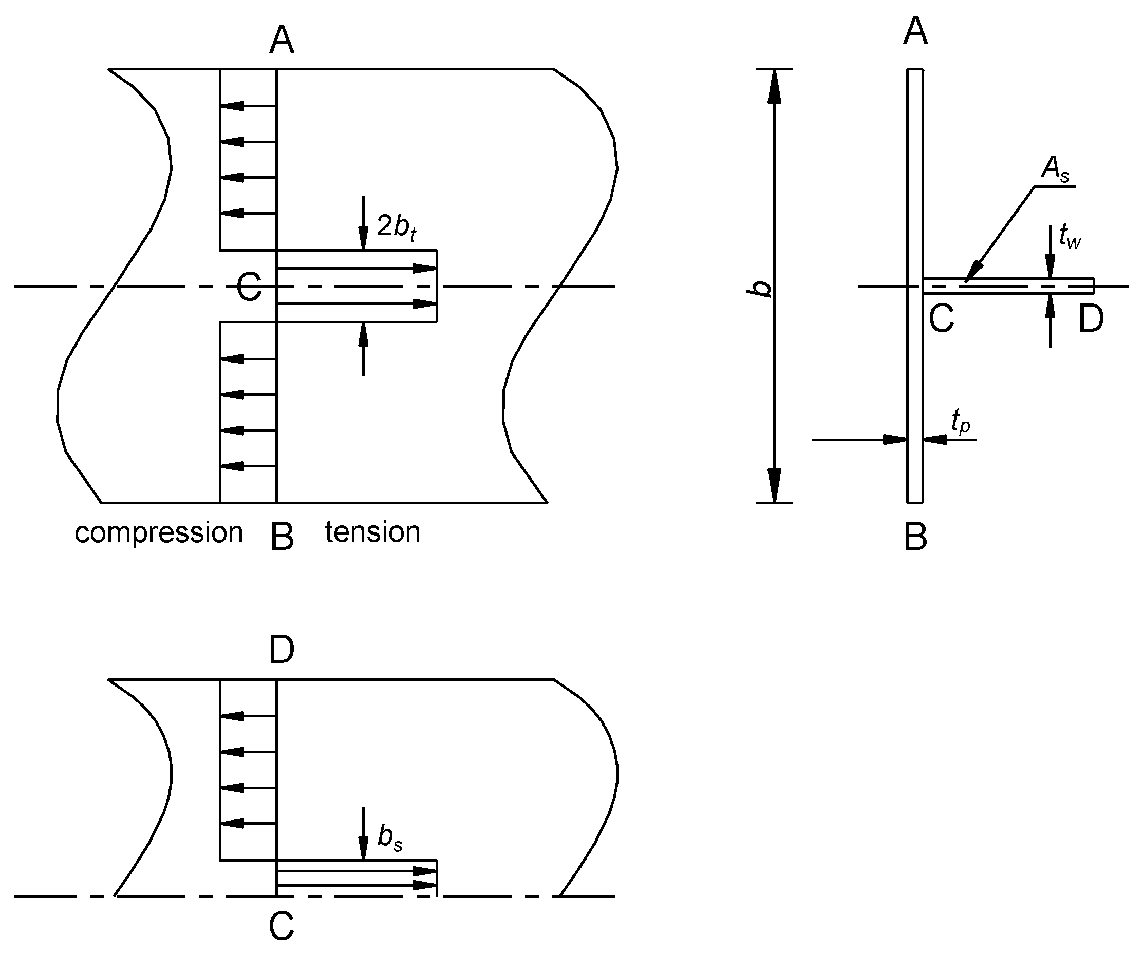
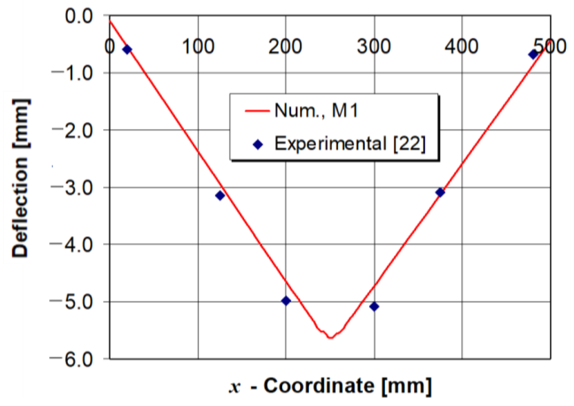
5.1. Residual Stress and Deflection Distributions—Reference Model

Since the obtained thermal field from the thermal analysis is a burden on the mechanical analysis, special attention is devoted to its accuracy. For this purpose, the numerically calculated peak temperatures of model M1 were compared with a more appropriate model from the literature [5], where the heat flux is defined as a combination of volumetric and Gaussian surface heat flux. Figure 6 shows the temperature histories of model M1 at nodes N1 and N2 for the first 250 s after the beginning of the welding process. The comparison of the peak temperatures between model M1 and the model from the literature is given in Table 4, where it can be seen that the differences are negligible. It can be concluded that the impact of the heat flux simplification has little effect on temperature distribution and that the model presented can be applied in the mechanical analysis.
Figure 7 shows the numerically calculated deflection distribution of the horizontal plate (deflection in y-direction) at the middle plane along the line A-B (Figure 1) for the reference model M1, after the completion of welding and cooling process to room temperature. The obtained numerical deflection corresponds very well with the experimental measurement. Figure 8 shows the longitudinal residual stress profile (σz, stress in z-direction) at the middle plane of the horizontal plate along the A-B line (Figure 1) compared with two analytical solutions from Equations (1) and (2). It can be seen that tensile residual stresses are in the weld area, while in the rest of the model they are compressive. The maximum numerically calculated tensile stresses are approximately 5% higher than the analytically calculated ones. The numerically calculated compressive stresses are very close to the analytical ones calculated according to Equations (1) and (2) of 48.2 MPa and 42.5 MPa, respectively. Comparing the numerically calculated width of the tensile zone with the analytically calculated values it can be seen that they corresponded well. The numerically calculated tensile zone width is approximately 4% lower than the analytically calculated ones. Based on these results, it can be concluded that the numerical model presented is sufficiently accurate and it can be applied to the other four numerical models given in Table 3.

5.2. Influence of Preheat Temperature on the Longitudinal Residual Stress and Horizontal Plate Deflection

Figure 9 shows a comparison of the numerically calculated horizontal plate deflections in the preheated models M2 and M3 compared with the reference model M1. Here it is evident that with an increase of the preheat temperature, the deflections of the horizontal plate significantly decrease. Unfortunately, the increase of the preheat temperature level is limited by several factors such as: welding technology, heat input, steel group, chemical composition, diffusible hydrogen, required microstructure, and plate thickness. As for the T-joint welded model discussed in this study, it should not exceed 150 °C according to the EN-1011-2 norm [38]. In the case of the preheat temperature being higher than prescribed in Reference [38], certain issues can be expected regarding the mechanical properties in the weld joint, especially in the weld metal, such as metal softening in the heat-affected zone. For the preheated models M2 and M3, the horizontal plate deflections are approximately 12% and 22% lower, respectively, in comparison with the reference model M1. If the entire volume of the T-joint model was hypothetically preheated at 150 °C prior to the start of welding, the peak deflection would be 4.5 mm which is very close to the value of the locally preheated model M3 used in this study, of 4.6 mm, i.e., the deflection differences are within a range of 2%. Furthermore, it should be pointed out that from an energy point of view, the use of local preheat leads to 76% in energy savings compared to preheating an entire model of the same dimensions. Keeping these two conclusions in mind, as well as the fact that the recommendations in the norm [38] are conservative, the model presented offers the possibility for structure volume optimization which is preheated.
Furthermore, Figure 10 shows that the preheat temperature increase minimally affects the longitudinal tensile stress and the tensile zone widths. However, the increase of preheat temperature significantly increases the longitudinal compressive stresses at the ends of the plates. Since the increase of temperature in the preheated part of the welded model causes its extension in the longitudinal direction, the non-preheated part resists it. It can be concluded that the application of the local preheating technique prior to welding causes higher pressure compressive residual stresses outside the weld area in comparison with the models where the entire volume is preheated before the start of welding [16]. This phenomenon will be far more visible in welded models with higher preheat temperatures than in the model analyzed in this study.

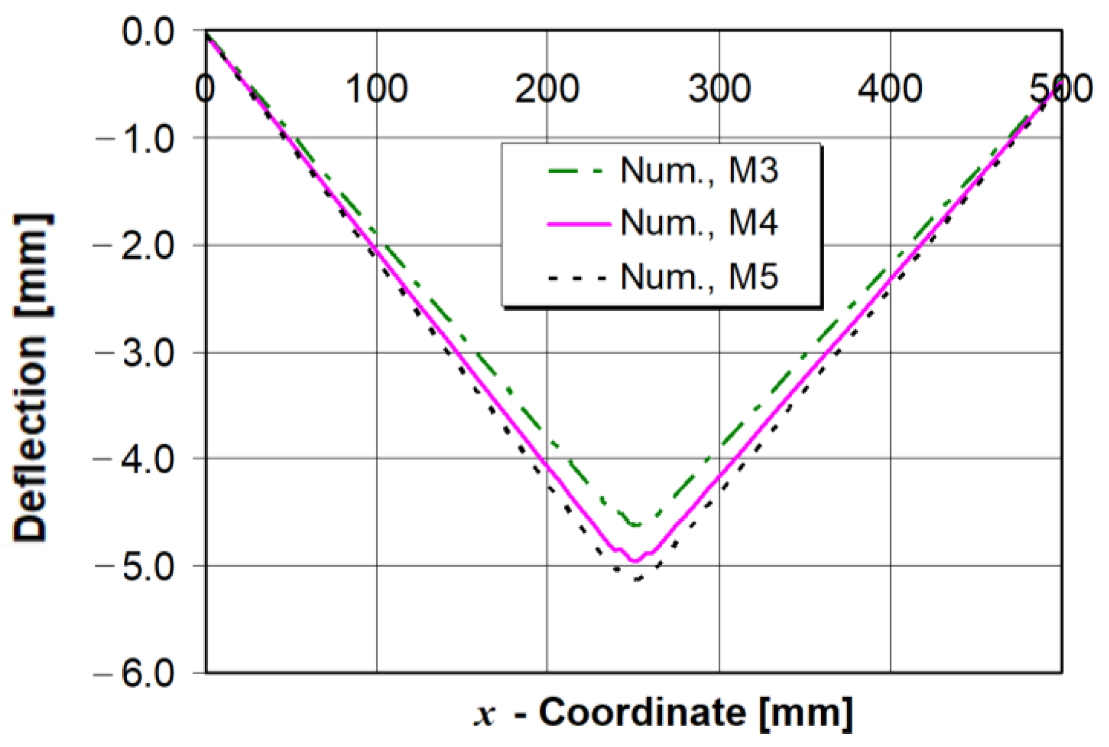
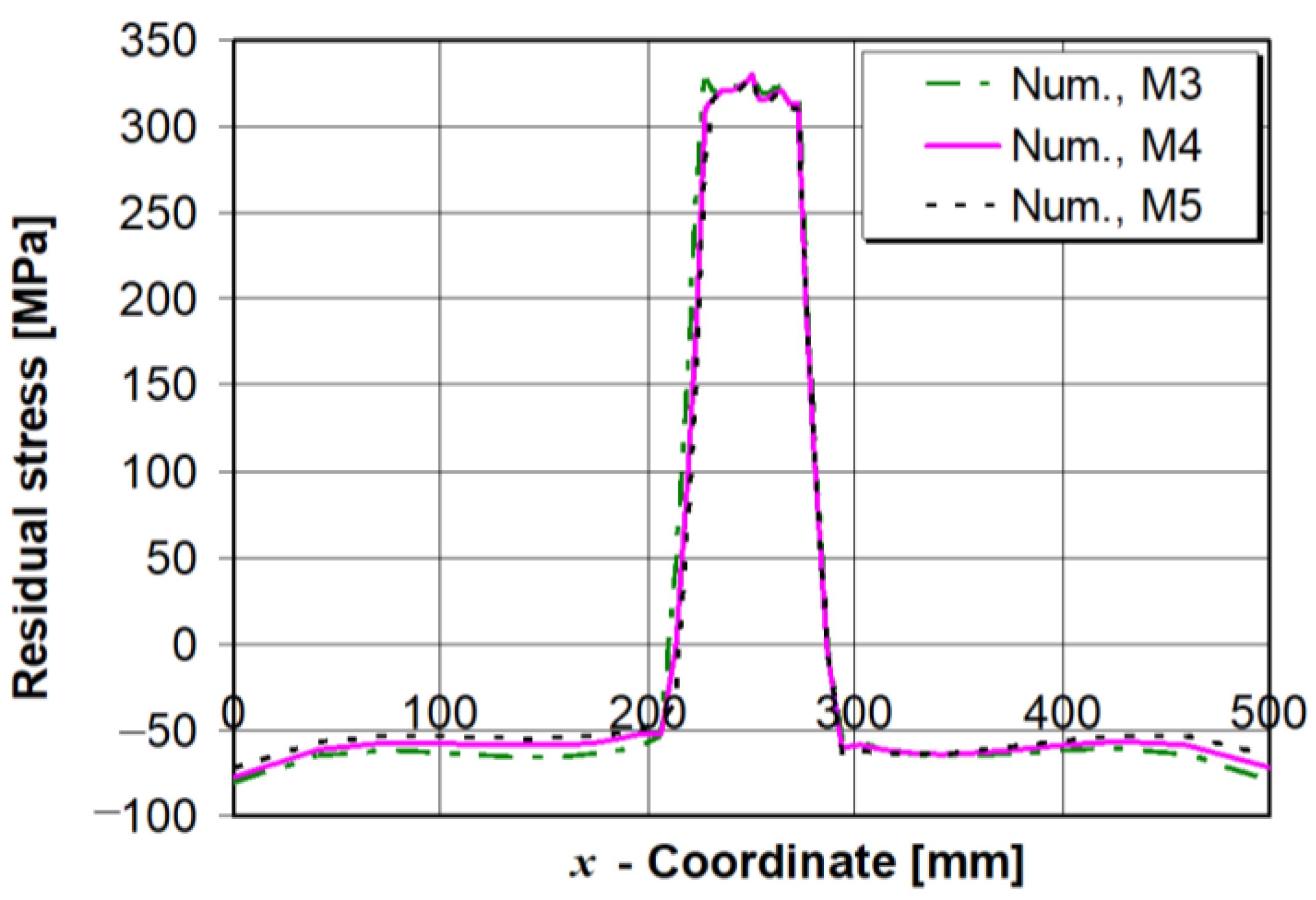
5.3. Influence of Interpass Time on the Longitudinal Residual Stress and Horizontal Plate Deflection

The influence of the interpass time between the two weld passes was investigated on the preheated models M4 and M5 and the obtained values were then compared with the M3 model where the interpass time was 0 s. Figure 11 shows that with the increase of interpass time, the horizontal plate deflection increased as well, because the positive effect of the preheat procedure vanishes during the cooling process. For example, when the interpass time is hypothetically extended up to approximately 70 min, the full model completely cools down to room temperature before the start of the second weld pass. In such a case the maximum horizontal plate deflection becomes only about 5% lower than in the reference model M1, without applying preheat and without interpass time application. It can be stated that when the interpass time is too long, the preheating procedure is almost useless. In Figure 12 it is shown that the influence of the interpass time on the longitudinal tensile residual stress and the width of the tensile stress zone can be neglected.
This is due to a smaller temperature gradient difference between the preheated and non-preheated parts of the model in comparison with models M1, M2 and M3 without the application of interpass time.

6. Conclusions

In this study, the influences of preheat temperature and interpass time on the longitudinal residual stress and vertical deflection of a T-joint fillet model were investigated. The local preheating technique, where the preheat temperature was kept constant only at the beginning of the welding process was simulated in the numerical calculations. The conclusions are as follows:
  • The increase of the preheat temperature decreases the horizontal plate deflection of a T-joint very quickly.
  • The influence of preheat temperature on the longitudinal tensile residual stress and the tensile stress zone width is negligible.
  • The application of local preheating increases the compressive longitudinal stresses due to the increased temperature gradients between the preheated and non-preheated parts of the model. This occurrence is much more pronounced than in the models where the entire volume is preheated before the start of welding.
  • The increase of interpass time increases the plate deflections. In cases when interpass time is prolonged, the positive effects of preheating vanish.
  • The increase of interpass time minimally affects the longitudinal tensile residual stress and its tensile zone width.
  • The effect of interpass time increase on compressive longitudinal stresses in preheated models can be neglected.
Generally speaking, the application of a local preheating procedure is very useful when the reduction of plate deflections is of primary concern. In this case, a preheat temperature should be imposed as high as practically possible, without interpass time, as was demonstrated with model M3. When the compressive longitudinal residual stress at the ends of the plates is minimized, the optimal solution is model M1 without any localized preheating and with no time gap between the two weld passes. In order to reduce the energy consumption that is needed for the preheat procedure, in the next phase of the investigations, the emphasis will be on optimization of the preheat zone size and temperature level in the high-productive buried arc welding of thick steel plates, when the heat inputs are very high.

Author Contributions

Conceptualization, methodology, data curation, investigation, writing—original draft preparation, formal analysis, funding acquisition, supervision and project administration, M.P.; data curation and supervision, I.G. and S.N.; data curation, H.D-J.

Funding

This research received no external funding.

Acknowledgments

The authors wish to express their deep gratitude to ISO Plus Croatia for financial support and to its engineers Ivica Cvrlje and Bruno Repar for their valuable comments.

Conflicts of Interest

The authors declare no conflicts of interest.

References

  1. Boljanović, S.; Maksimović, S. Computational mixed mode failure analysis under fatigue loadings with constant amplitude and overload. Eng. Fract. Mech. 2017, 174, 168–179. [Google Scholar] [CrossRef]
  2. Chen, Z.; Xiong, Y.; Qiu, H.; Lin, G.; Li, Z. Stress intensity factor-based prediction of solidification crack growth during welding of high strength steel. J. Mater. Process. Technol. 2018, 252, 270–278. [Google Scholar] [CrossRef]
  3. Oh, S.H.; Ryu, T.Y.; Park, S.H.; Won, M.G.; Kang, S.J.; Lee, K.S.; Lee, S.H.; Kim, M.K.; Choi, J.B. Evaluation of J-groove weld residual stress and crack growth rate of PWSCC in reactor pressure vessel closure head. J. Mech. Sci. Technol. 2015, 29, 1225–1230. [Google Scholar] [CrossRef]
  4. Božić, Ž.; Schmauder, S.; Wolf, H. The effect of residual stresses on fatigue crack propagation in welded stiffened panels. Eng. Fail. Anal. 2018, 84, 346–357. [Google Scholar] [CrossRef]
  5. Gannon, L.; Liu, Y.; Pegg, M.; Smith, M. Effect of welding sequence on residual stress and distortion in flat-bar stiffened plates. Mar. Struct. 2010, 23, 385–404. [Google Scholar] [CrossRef]
  6. Fu, G.M.; Lourenço, I.L.; Duan, M.; Estefen, S.E. Influence of the welding sequence on residual stress and distortion of fillet welded structures. Mar. Struct. 2016, 46, 30–55. [Google Scholar] [CrossRef]
  7. Jiang, W.; Yahiaoui, K. Effect of welding sequence on residual stress distribution in a multipass welded piping branch junction. Int. J. Press. Vessels Pip. 2012, 95, 39–47. [Google Scholar] [CrossRef]
  8. Li, Y.; Yoshiyuki, K.; Igarashi, K. Effects of thermal load and cooling condition on weld residual stress in a core shroud with numerical simulation. Nucl. Eng. Des. 2012, 242, 100–107. [Google Scholar] [CrossRef]
  9. Moat, R.J.; Stone, H.J.; Shirzadi, A.A.; Francis, J.A.; Kundu, S.; Mark, A.F.; Bhadesia, H.K.D.H.; Karlsson, L.; Withers, P.J. Design of weld fillers for mitigation of residual stresses in ferritic and austenitic steel welds. Sci. Technol. Weld. Join. 2011, 16, 279–284. [Google Scholar] [CrossRef]
  10. Cozzolino, L.D.; Coules, E.; Colegrove, A.P.; Wen, S. Investigation of post-weld rolling methods to reduce residual stress and distortion. J. Mater. Process. Technol. 2017, 247, 243–256. [Google Scholar] [CrossRef]
  11. Schenk, T.; Richardson, I.M.; Kraska, M.; Ohnimus, S. Influence of clamping on distortion of welded S355 T-joints. Sci. Technol. Weld. Join. 2009, 14, 369–375. [Google Scholar] [CrossRef]
  12. Chuvas, T.C.; Castello, D.A.; Fonseca, M.P.C. Residual stress relief of welded joints by mechanical vibrations. J. Braz. Soc. Mech. Sci. Eng. 2016, 38, 2449–2457. [Google Scholar] [CrossRef]
  13. Yang, Y.P. Understanding of vibration stress relief with computation modeling. J. Mater. Eng. Perform. 2009, 18, 856–862. [Google Scholar] [CrossRef]
  14. Samardžić, I.; Vuherer, T.; Marić, D.; Konjatić, P. Influence of vibrations on residual stresses distribution in welded joints. Metalurgija 2015, 54, 527–530. [Google Scholar]
  15. Dong, P.; Song, S.; Zhang, J. Analysis of residual stress relief mechanisms in post-weld heat treatment. Int. J. Press. Vessels Pip. 2014, 122, 6–14. [Google Scholar] [CrossRef]
  16. Fu, G.M.; Lourenço, I.L.; Duan, M.; Estefen, S.E. Effects of preheat and interpass temperature on the residual stress and distortion on the T-joint weld. In Proceedings of the ASME 2014 33rd International Conference on Ocean, Offshore and Arctic Engineering OMAE2014, San Francisco, CA, USA, 8–13 June 2014. [Google Scholar]
  17. Kala, S.R.; Prasad, N.S.; Phanikumar, G. Numerical studies on effect of interpass time on distortion and residual stresses in multipass welding. Adv. Mater. Res. 2013, 601, 31–36. [Google Scholar] [CrossRef]
  18. Ilman, M.N.; Kusmono; Muslih, M.R.; Subeki, N.; Wibovo, H. Mitigating distortion and residual stress by static thermal tensioning to improve fatigue crack growth performance of MIG AA5083 welds. Mater. Des. 2016, 99, 273–283. [Google Scholar] [CrossRef]
  19. Zhang, W.; Fu, H.; Fan, J.; Li, R.; Xu, H.; Liu, F.; Qi, B. Influence of multi-beam preheating temperature and stress on the buckling distortion in electron beam welding. Mater. Des. 2018, 139, 439–446. [Google Scholar] [CrossRef]
  20. Okano, S.; Mochizuki, M. Experimental and numerical investigation of trailing heat sink effect on weld residual stress and distortion of austenitic stainless steel. ISIJ Int. 2016, 56, 647–653. [Google Scholar] [CrossRef]
  21. Zubairuddin, M.; Albert, S.K.; Vasudevan, M.; Mahadevan, S.; Chaudri, V.; Suri, V.K. Thermo-mechanical analysis of preheat effect on grade P91 steel during GTA welding. Mater. Manuf. Process. 2016, 31, 366–371. [Google Scholar] [CrossRef]
  22. Deng, D.; Liang, W.; Murakawa, H. Determination of welding deformation in fillet-welded joint by means of numerical simulation and comparison with experimental measurements. J. Mater. Process. Technol. 2007, 183, 219–225. [Google Scholar] [CrossRef]
  23. Yao, T.; Astrup, O.C.; Caridis, P.; Chen, Y.N.; Cho, S.R.; Dow, R.S.; Niho, O.; Rigo, P. Ultimate hull girder strength. In Proceedings of the 14th International Ship and Offshore Structure Congress, Nagasaki, Japan, 2–6 October 2000; Volume 2, pp. 323–333. [Google Scholar]
  24. Chen, B.K.; Soares, G.C. Effects of plate configurations on the weld induced deformations and strength of fillet-welded plates. Mar. Struct. 2016, 50, 243–259. [Google Scholar] [CrossRef]
  25. Gannon, L.; Liu, Y.; Peg, N.; Smith, M.J. Effect of welding-induced residual stress and distortion on ship hull girder ultimate strength. Mar. Struct. 2012, 25, 25–49. [Google Scholar] [CrossRef]
  26. Perić, M.; Tonković, Z.; Rodić, A.; Surjak, M.; Garašić, I.; Boras, I.; Švaić, S. Numerical analysis and experimental investigation in a T-joint fillet weld. Mater. Des. 2014, 53, 1052–1063. [Google Scholar] [CrossRef]
  27. Perić, M.; Stamenković, D.; Milković, V. Comparison of residual stresses in butt-welded plates using software packages Abaqus and Ansys. Sci. Tech. Rev. 2010, 60, 22–26. [Google Scholar]
  28. Chen, Z.; Gongrong, L. A study on the spring-back deflections and constraint forces of a bottom grillage cling welding. Ships Offshore Struct. 2017, 12, 1077–1085. [Google Scholar] [CrossRef]
  29. Lostado, R.L.; Garcia, R.E.; Martinez, R.F.; Martinez Calvo, M.A. Using genetic algorithms with multi-objective optimization to adjust finite element models of welded joints. Metals 2018, 8, 230. [Google Scholar] [CrossRef]
  30. EN 1011-1. Welding—Recomendations for welding of metallic materials—Part 1. General guidance for arc welding. Change 2009, 30, 9. [Google Scholar]
  31. Seleš, K.; Perić, M.; Tonković, Z. Numerical simulation of a welding process using a prescribed temperature approach. J. Constr. Steel Res. 2018, 145, 49–57. [Google Scholar] [CrossRef]
  32. Perić, M.; Tonković, Z.; Garašić, I.; Vuherer, T. An engineering approach for a T-joint fillet welding simulation using simplified material properties. Ocean Eng. 2016, 128, 13–21. [Google Scholar] [CrossRef]
  33. Menéndez, M.C.; Rodríguez, E.; Ottolini, M.; Caixas, J.; Guirao, J. Analysis of the effect of the electron-beam welding sequence for a fixed manufacturing route using finite element simulations applied to ITER vacuum vessel manufacture. Fusion Eng. Des. 2016, 104, 84–92. [Google Scholar] [CrossRef]
  34. Perić, M.; Tonković, Z.; Karšaj, I.; Stamenković, D. A simplified engineering method for a T-joint welding simulation. Therm. Sci. 2018, 22, S867–S873. [Google Scholar] [CrossRef]
  35. Deng, D. FEM prediction of welding residual stress and distortion in carbon steel considering phase transformation effects. Mater. Des. 2009, 30, 359–366. [Google Scholar] [CrossRef]
  36. Marenić, E.; Skozrit, I.; Tonković, Z. On the calculation of stress intensity factors and J-integrals using the submodeling technique. J. Press. Vessel Technol. 2010, 132, 041203–041212. [Google Scholar] [CrossRef]
  37. ISO (International Organization for Standardization). Welding—Measurement of Preheating Temperature, Interpass Temperature and Preheat Maintenance Temperature; ISO: Geneva, Switzerland, 2017. [Google Scholar]
  38. EN 1011-2. Welding—Recommentations for welding of metallic materials—Part 2: Arc welding of ferritic steels. Change 2001, 30, 15–23. [Google Scholar]
Figure 1. T-joint geometry and volume of preheating.
Energies 11 03487 g001
Figure 2. Thermal properties of SM400A steel [22].
Energies 11 03487 g002
Figure 3. Mechanical properties of SM400A steel [22].
Energies 11 03487 g003
Figure 4. Idealised longitudinal residual stress distribution [23].
Energies 11 03487 g004
Figure 5. T-joint finite elements mesh.
Energies 11 03487 g005
Figure 6. Temperature histories at nodes N1 and N2 (Figure 1).
Energies 11 03487 g006
Figure 7. Middle-plane deflection profile along A-B line (Figure 1), model M1.
Energies 11 03487 g007
Figure 8. Middle-plane longitudinal residual stress profile along A-B line (Figure 1), model M1.
Energies 11 03487 g008
Figure 9. Middle-plane deflection profile along A-B line (Figure 1), models M1, M2 and M3.
Energies 11 03487 g009
Figure 10. Middle-plane longitudinal residual stress profile along A-B line (Figure 1), models M1, M2 and M3.
Energies 11 03487 g010
Figure 11. Middle-plane deflection profile along A-B line (Figure 1), models M3, M4 and M5.
Energies 11 03487 g011
Figure 12. Middle-plane residual stress profile along A-B line (Figure 1), models M3, M4 and M5.
Energies 11 03487 g012
Table 1. Welding conditions [22].
Welding Current (A)Welding Voltage (V)Welding Speed (mm/min)Angle of Torch (°)
2702940045
Table 2. Elemental composition of SM400A steel (mass%) [22].
CSiMnPS
0.23-0.56<0.035<0.035
Table 3. List of the simulated numerical models.
Model NamePreheating ApplicationInterpass Time
M1Not = 0 s
M2Yes, T = 100 °Ct = 0 s
M3Yes, T = 150 °Ct = 0 s
M4Yes, T = 150 °Ct = 60 s
M5Yes, T = 150 °Ct = 120 s
Table 4. Peak temperatures at nodes N1 and N2.
Peak Temperatures (°C)Node N1
(1st Pass)
Node N2
(1st Pass)
Node N1
(2nd Pass)
Node N1
(2nd Pass)
Current study1712496398381
Gannon et. al. [5]1730500374356

