Experimental Research on the Injection Rate of DME and Diesel Fuel in Common Rail Injection System by Using Bosch and Zeuch Methods

1
Leaders in Industry-University Cooperation (LINC) of Chosun University, 309 Pilmun-daero, Dong-gu, Gwangju 61452, Korea
2
Department of Mechanical and Automotive Engineering, Songwon University, Songarm-ro, Gwangju 61756, Korea
*
Author to whom correspondence should be addressed.
Energies 2018, 11(2), 273; https://doi.org/10.3390/en11020273
Submission received: 12 December 2017
/
Revised: 18 January 2018
/
Accepted: 18 January 2018
/
Published: 23 January 2018
(This article belongs to the Section I: Energy Fundamentals and Conversion)
Abstract
:This study investigates a preliminary injection characterization of the injection rate and the injection quantity behavior in a high-pressure common rail injection system used in a heavy-duty engine. The injection rate meter and the injection quantity meter used in the test meter measuring systems were jointly connected under the Zeuch method measurement principles at a constant volume chamber and under the Bosch method measurement principles at a long pipe flow. The trade-off trend for the injection rate and the injection quantity was observed according to the injection pressure. As expected, fuel injection with pilot injection affected the spray quantity and the injection evolution of subsequent fuel injection without pilot injection in dimethyl ether and diesel fuel. The pressure variations in the initial injection duration (2000–6000 µs) of the main and pilot injections for diesel and DME were similar. However, after 7000 µs, the pressure of DME increased more rapidly compared to that of diesel. This finding was the result of the rapid density changes caused by the nature of compressive fluid. Therefore, the DME supply pump was expected to require a higher drive energy by approximately 20% compared to that of the diesel supply pump.
1. Introduction
The use of the current diesel injection pump or common rail system as the injection device for dimethyl ether (DME), which is a compressive oil, poses many problems. One of the major problems is the lubricity of DME being lower than that of diesel by more than 50%, which can cause sticking between the plunger and the barrel in a mechanical pump, sticking of a plunger in a high-pressure supply pump of a common rail system, and sticking of an injector in a solenoid valve and a nozzle in a needle valve. Studies are being actively conducted to improve the existing injection devices or develop new ones and solve these problems [1,2,3]. A previous study showed that the fuel injection system of the common rail type can independently control the injection amount by pressure, injection duration, and timing from the revolutions per minute (rpm) and load factor of the engine, thereby improving power and reducing emissions [4]. To control ignition timing, exhaust gas recirculation rate and operating regions in a premixed DME HCCI (Homogeneous Charged Compression Ignition) was realized on the ultra-low NOx and smokeless emission with induced DME as the main fuel [5,6,7,8] and investigated on the effects of the combustion phasing with exhaust gas recirculation loop for external EGR (Exhaust Gas Recirculation) [9].
Furthermore, pilot injection—which is a characteristic of the common rail system—can shorten the ignition delay and increase the heat generation rate, thereby reducing combustion noise and nitrogen oxide emissions [10]. The research on the effects of the spray angle and injection strategies (single injection, multi-injection, etc.) on the combustion characteristics [11,12,13,14] which are composed of particle size distribution [13], spray characteristics in a various pressure condition [14,15,16], combustion and emission performances, and EGR rate [17]—was investigated via numerical and experimental methodologies. Homogeneous charge compression ignition (HCCI) and bulk combustion were also investigated. The results, including those of diesel high-pressure injection and the effects of injection timing (e.g., pre-injection pilot-injection, main-injection, after-injection, and post-injection) on the engine, had been sufficiently reported. However, no satisfactory research results have yet been presented as regards the development and projection of specific injection systems for fuel supply according to the fuel characteristics, especially regarding DME. The injection rate and the injection quantity were measured using the Bosch tube method and the Zeuch method for measuring the injection rate of fuel due to the characteristics of DME fuel. The fuel injection rate characteristics were analyzed using the Bosch tube method and it was difficult to measure the fuel volume by using the fuel quantity as DME fuel changes from its atmospheric pressure to its gaseous state. In this study, the key is to measure the injection rate and the injection quantity of compressed DME fuel.
In this study, we apply DME and diesel fuels to a common rail injection system and examine the pilot injection rate according to the injection pressure and timing when the fuels are injected using an injector with an injection rate meter and an injection quantity chamber meter (model: CATEL-R01) produced and installed in our institution. Furthermore, the cause of the decreasing injection quantity due to response loss and friction loss generated while the needle valve is activated by fuel spill is investigated as a result of the activation of the solenoid valve by the TWV pulse from the ECU.
2. Experimental Apparatus and Methodology
2.1. Experimental Setup
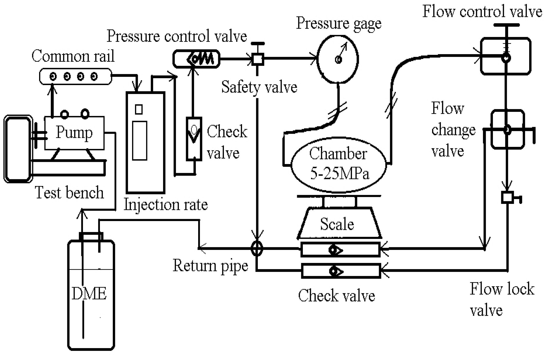
Table 1 lists the specifications of the injection rate meter and the quantity meter used in this experiment. Figure 1 shows the schematic. The injection rate meter used the Bosch method, while the injection quantity meter used the Bosch–Zeuch method, applied the Zeuch method and combined a flexible plastic hose. The Bosch tube rate of the injection meter [18,19] records the injection rate by measuring the pressure curve which is produced by injection as it injected into a length of compressible fluid. The Zeuch method [20,21,22] records the pressure of a constant volume chamber as an injection into the chamber occurs. When the mass of fuel in the chamber increases, the pressure of chamber must increase. In this paper, the principles of Bosch–Zeuch method are applied. Due to the characteristics of DME fuel, it is difficult to measure the exact injection quantity because it changes from room temperature to the gas phase. The injection amount in the chamber was measured using Zeuch method and Bosch tube method. The injection quantities of diesel and DME accumulated in a static chamber for 60 s were weighed using a scale.
Table 2 shows the specification of DME and diesel fuel properties.
2.2. Experimental Conditions
3. Results and Investigations
3.1. Injection Pressure in Accordance with Injection Duration
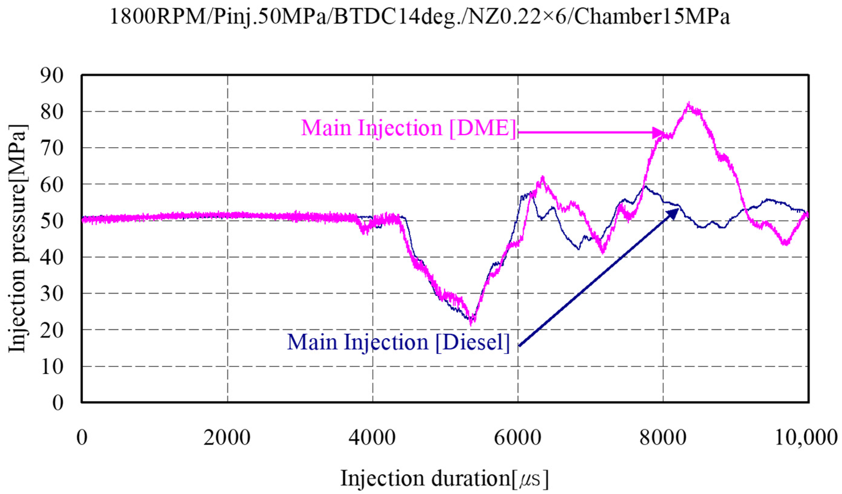
Figure 5 shows the line pressures between the fuel rail and the injector during the main injection period of diesel and DME. The initial pressure variations were similar, but the pressure of DME increased more rapidly than that of diesel after 7000 µs because of the rapid change in density caused by the nature of the compressive fluid. This result suggested that the DME supply pump required 20% more energy compared to the diesel supply pump.
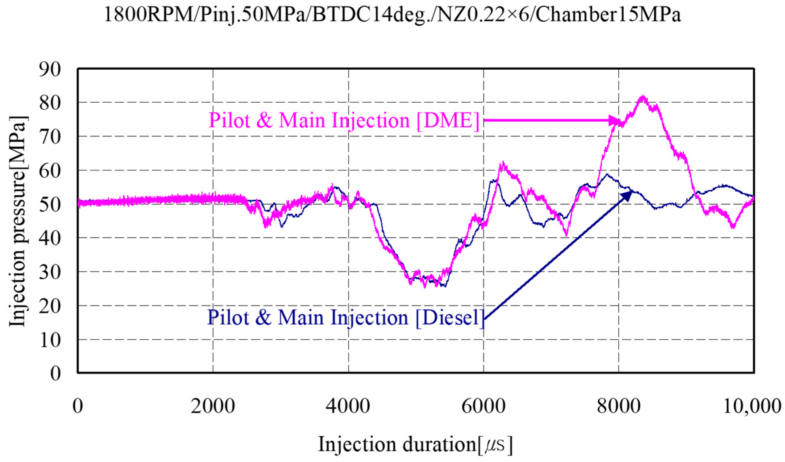
Figure 6 illustrates the result of the pilot injection under the conditions of Figure 1. DME and diesel were injected under the same conditions. However, DME was injected 200 µs earlier than diesel, showing that DME with a fuel density lower than that of diesel at a constant pressure condition would result in earlier fuel spill and fuel injection.
3.2. Needle Lift Variations in Accordance with Injection Timing
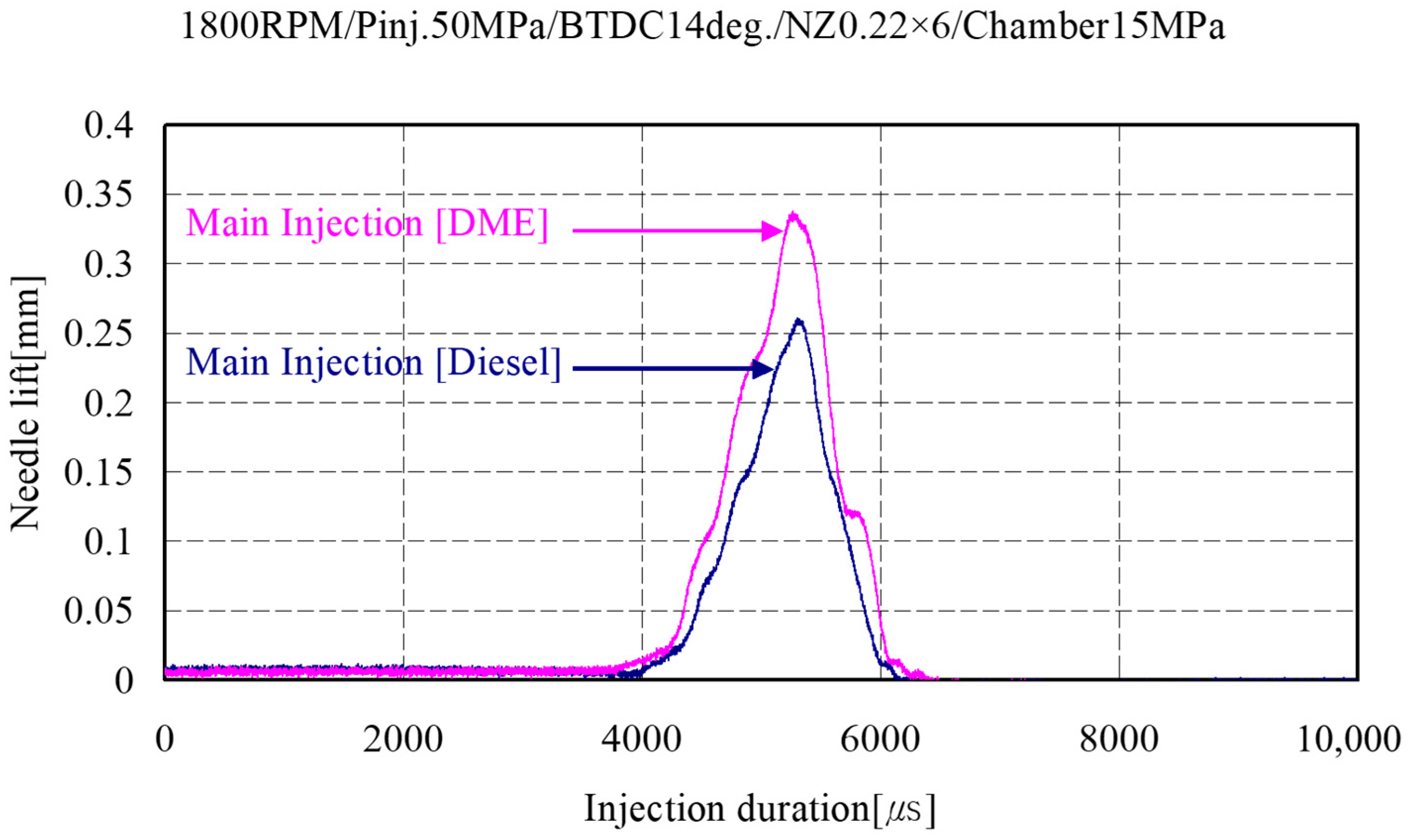
Figure 7 shows the needle lift operation times according to the main injection duration for DME and diesel. The needle lift variation in a fixed injection duration was 0.25 mm for diesel and 0.35 mm for DME, indicating that DME had a larger fuel consumption per unit time than diesel for fuel supply to the engine.
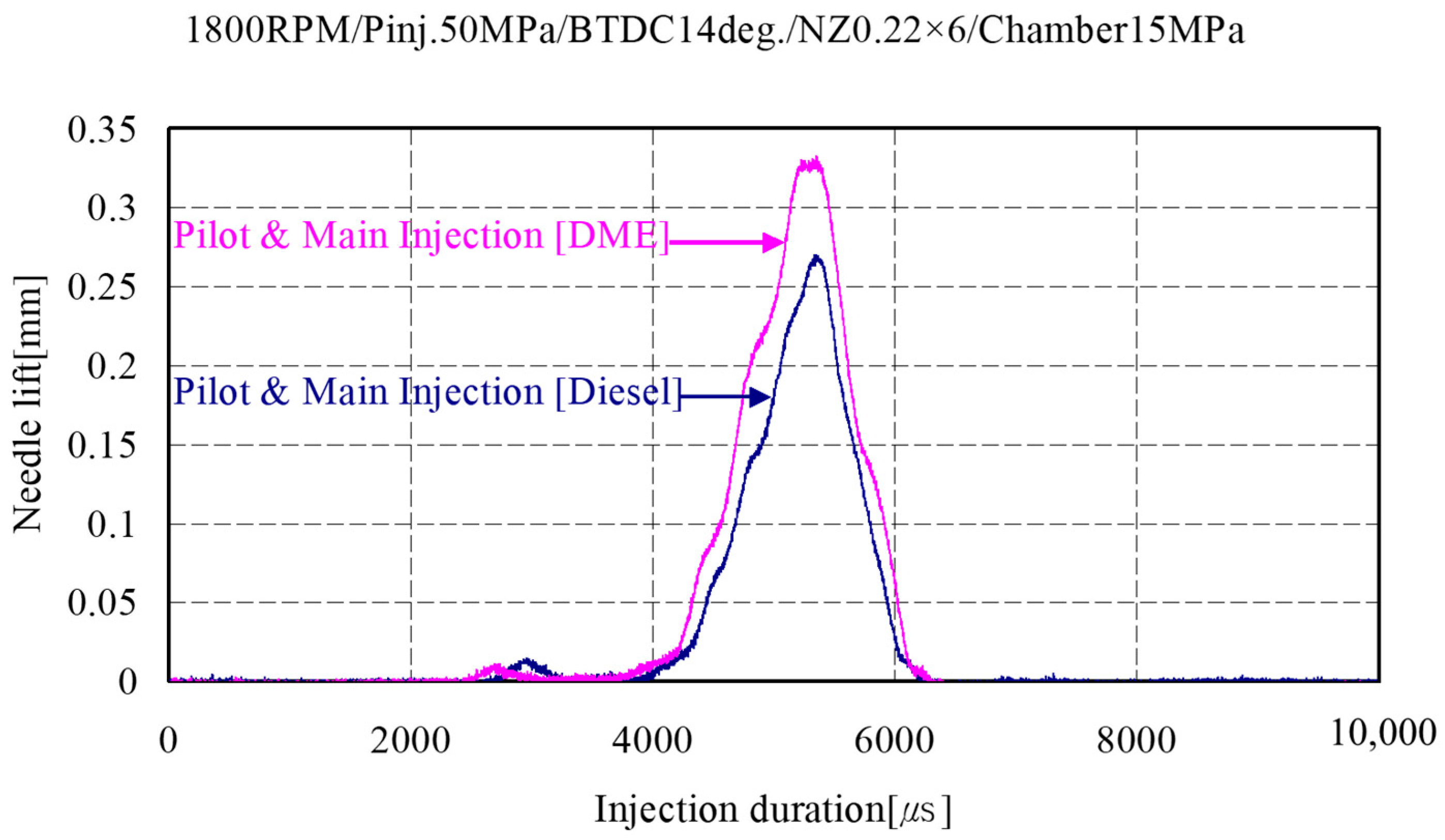
Figure 8 depicts the needle lift operation times by fuel spill with TWV (Two-way valve) pulse generation according to the pilot and main injection durations for DME and diesel. This figure illustrates that the needle lift operation time was lower for the pilot injection quantity during the pilot injection of diesel and DME. In other words, the main injection quantity when the fuel supply quantity was constant was lower by the pilot injection quantity, showing a close relationship between fuel consumption and the brake thermal efficiency of the engine.
3.3. Injection Rate and Amount in Accordance with Changing Pilot and Main Injection Timing
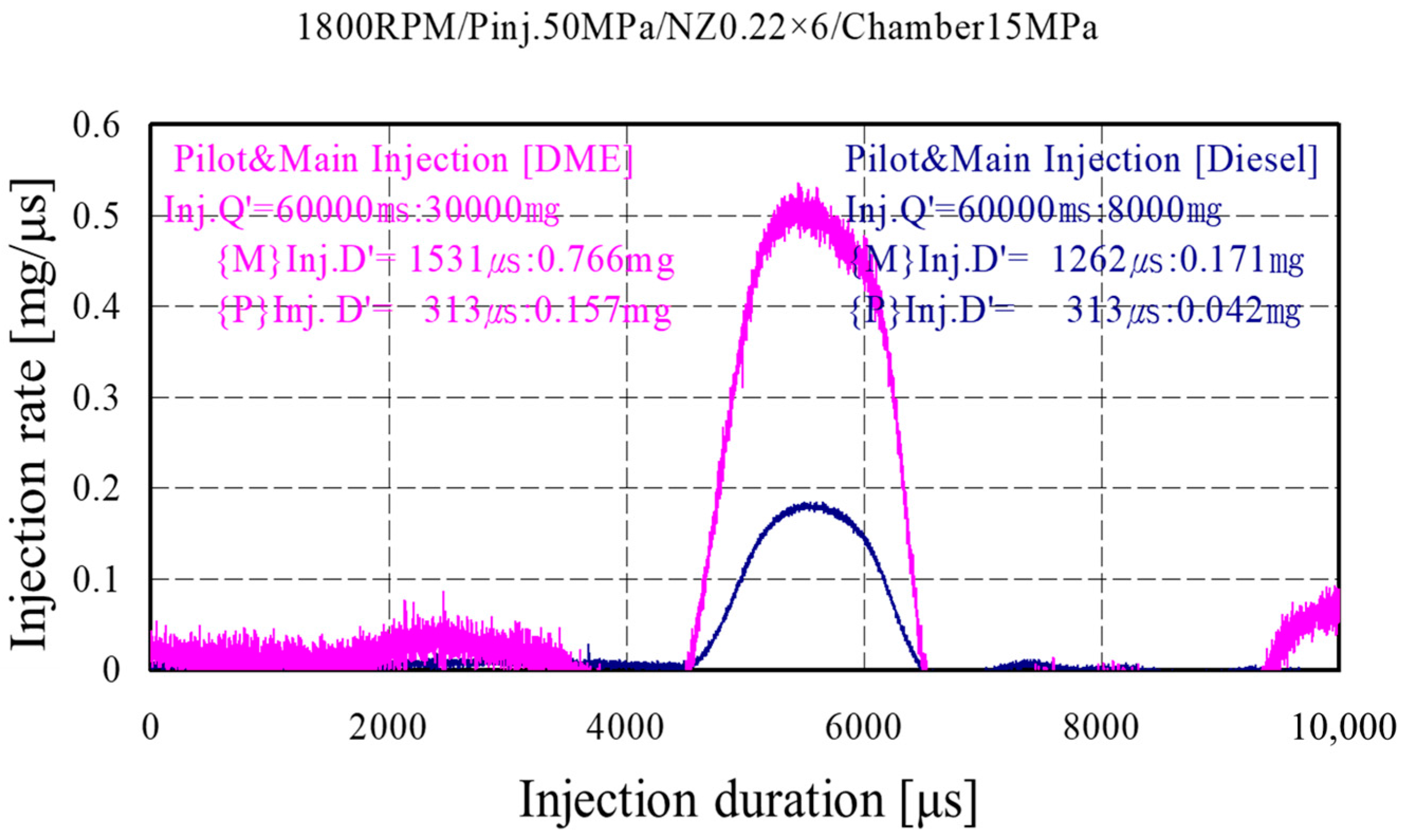
Figure 9 shows the injection rates expressed by the injection quantity per unit time of injection by the needle lift operation resulting from the fuel spill with the TWV pulse according to the pilot and main injection durations for DME and diesel. The injection quantity for an injection duration of 60,000 ms (6 × 10⁷ µs) was 30,000 mg for DME and 8000 mg for diesel. These results were obtained based on the measurement results of the injection quantity.
The injection quantity in the case of DME is increased more than that of diesel. The reason is that the low heating value of diesel is higher than that of DME. This result suggests that the injection duration when DME was used as a substitute fuel for diesel can be delayed by approximately 20%, and the injection quantity can increase by 30%, which can lead to increased fuel consumption. This value corresponded to the fact that the low heating value of DME was lower by approximately 40% than that of diesel.
3.3.1. DME Injection Quantity by Trend Line
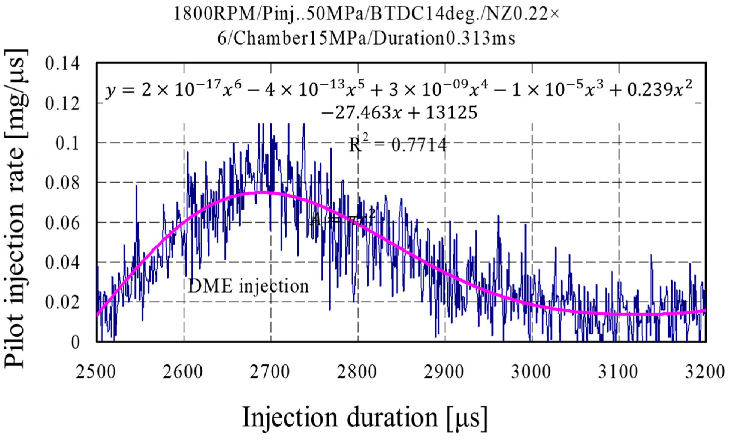
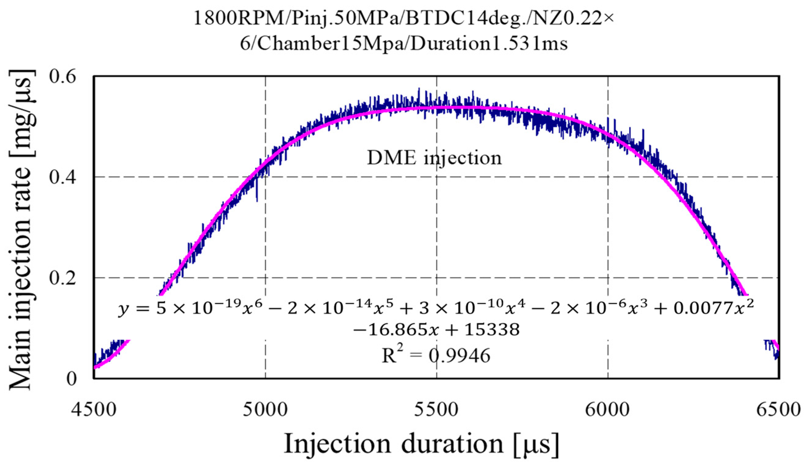
Figure 10 and Figure 11 show the pilot and main injection quantities of DME obtained by applying equations according to a detailed trend line for the measured injection quantity pulses in Figure 9. The purpose of injection according to such a trend line was to separately examine the injection rate and the quantity for pilot and main injections in multiple injections. The following equations express the abnormal compressive fluid under a single pressure according to a trend line
where the injection rate is proportional to pressure and, thus, can be expressed as follows as a time change for the inner pressure of the pipe
where, A is section area of tube, is fuel density, is liquid velocity, and is velocity of sound.
3.3.2. Diesel Injection Quantity by Trend Line
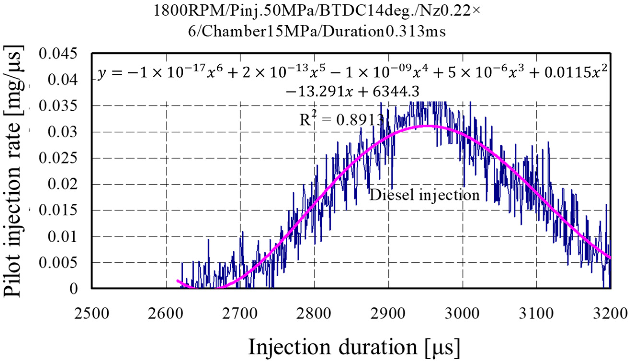
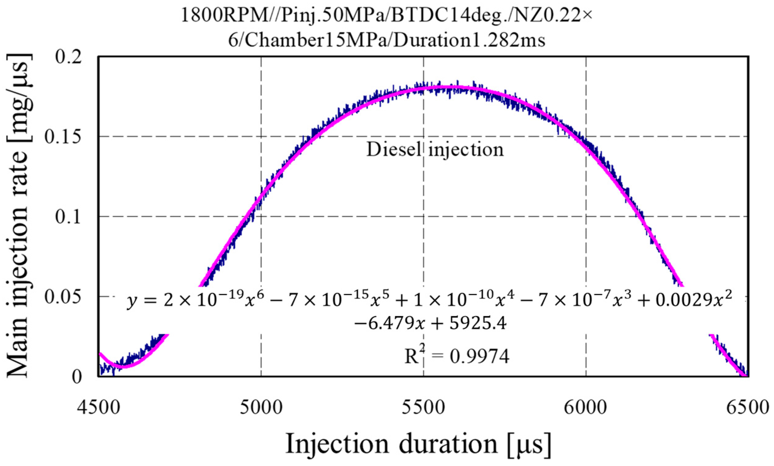
Figure 12 and Figure 13 depict the pilot and main injection quantities for the pilot and main injection durations of diesel. The diesel pilot injection duration was approximately between 2700 µs and 3200 µs. Thus, the total injection period was approximately 500 µs, which was similar to the DME injection duration between 2500 µs and 3000 µs. However, the injection start point of DME was earlier by 200 µs, indicating that the spill of the injector solenoid valve and the needle lift started earlier. The injection timing of DME occurred earlier than that of diesel because the liquid density and the kinematic viscosity of DME were lower by 20% and 30%, respectively, than those of diesel. Furthermore, the main injection timing and duration also showed similar trends.
4. Conclusions
The effects of the TWV pulse, pressure variations, and nozzle needle lift by fuel spill, injection rate by injection pressure, and injection quantity according to the injection rate on the pilot and main injections were examined herein before application to the experimental engine to obtain the basic data required for engine experimentation in the future. We particularly examined the optimum injection pressure, needle lift, pilot injection rate, main injection quantity, and injection timing according to the injection duration when the current high-pressure electronic common rail was applied to an engine using a high-pressure fuel injection system by a common rail. The conclusions obtained from this study are summarized as follows:
- The pressure variations in the initial injection duration (2000–6000 µs) of the main and pilot injections for diesel and DME were similar. However, after 7000 µs, the pressure of DME increased more rapidly compared to that of diesel. This finding was the result of the rapid density changes caused by the nature of compressive fluid. Therefore, the DME supply pump was expected to require a higher drive energy by approximately 20% compared to that of the diesel supply pump.
- The maximum variation during the needle lift operation was 0.25 ms for diesel and 0.35 ms for DME. Thus, that of DME was higher by 0.1 m or 29% because DME had a higher fuel consumption per unit time for fuel supply to the engine based on weight than diesel.
- The TWV pulse and the injection start time showed a difference of 1 ms in the injection rate according to the injection pressure. Unlike the mechanical supply pump that used a mechanical advancer, the common rail system was activated by the injector solenoid based on the ECU pulse. Thus, a difference between the electronic speed and the mechanical speed was observed, and the ECU program will have to consider the advancer.
- The solenoid response decreased as the needle lift operation time increased, resulting in a loss of the discharge flow. Although the injection duration and quantity were changed by the injection pressure, they were also changed by the injection duration. Thus, this characteristic must be considered when applying the common rail injection system. Furthermore, the larger the needle lift, the greater the loss of the injection quantity.
- The typical method of measuring the injection quantity per unit time of DME is to measure the injection quantity accumulated in a pressure vessel. However, one problem encountered in this method is that the chamber vessel, connecting parts, and valves can be damaged because of the chamber pressure being increased by the cumulative injection quantity.
- Based on the injection rate and quantity measurement experiment for DME in this study, we propose the Bosch–Zeuch injection rate measurement method, which combines the Bosch and Zeuch methods.
Acknowledgments
This study was supported by the development of key fusion technology of the industrial–academic research cooperation cluster support project.
Author Contributions
Seomoon Yang and Changhee Lee conceived and designed the experiments; Seomoon Yang performed the experiments; Changhee Lee analyzed the data; Seomoon Yang contributed reagents/materials/analysis tools; Changhee Lee wrote the paper.
Conflicts of Interest
The authors declare no conflict of interest.
References
- Kajitani, S.; Chen, Z.L.; Konno, M. Engine Performance and Exhaust Characteristics of Direct-Injection Diesel Engine Operated with DME; SAE 972973; SAE International: Warrendale, PA, USA, 1997. [Google Scholar]
- Fleisch, T.H.; Basu, A.; Gradassi, M.J.; Masin, J.G. Dimethyl ether: A fuel for the 21st century. Stud. Surf. Sci. Catal. 1997, 107, 117–125. [Google Scholar]
- Ikeda, T.; Ohmori, Y.; Takamura, A.; Sato, Y.; Jun, L.; Kamimoto, T. Measurement of the Rate of Multiple Fuel Injection with Diesel Fuel and DME; SAE Technical Paper 2001-01-0527; SAE International: Warrendale, PA, USA, 2001. [Google Scholar]
- Diesel EMS and Injection Engineering Department, ECD-U2 System Operation Manual (for Rir Test & Engine Test); DENSO Co.: Kariya, Japan, 1996.
- Ogawa, H.; Miyamoto, N.; Kaneko, N.; Ando, H. Combustion Control and Operating Range Expansion with Direct Injection of Reaction Suppressors in a Premixed DME HCCI Engine; SAE No. 2003-01-0746; SAE International: Warrendale, PA, USA, 2003. [Google Scholar]
- Arcoumanis, C.; Bae, C.; Crookes, R.; Kinoshita, E. The potential of di-methyl ether (DME) as an alternative fuel for compression-ignition engines: A review. Fuel 2008, 87, 1014–1030. [Google Scholar] [CrossRef]
- Ying, W.; Li, H.; Jie, Z.; Longbao, Z. Study of HCCI-DI combustion and emissions in a DME engine. Fuel 2009, 88, 2255–2261. [Google Scholar] [CrossRef]
- Kim, H.J.; Lee, K.S.; Lee, C.S. A study on the reduction of exhaust emissions through HCCI combustion by using a narrow spray angle and advanced injection timing in a DME engine. Fuel Proc. Technol. 2011, 92, 1756–1763. [Google Scholar] [CrossRef]
- Jung, D.; Iida, N. Closed-loop control of HCCI combustion for DME using external EGR and rebreathed EGR to reduce pressure-rise rate with combustion-phasing retard. Appl. Energy 2015, 138, 315–330. [Google Scholar] [CrossRef]
- Daisho, Y. Future vehicle technologies for low emission and high efficiency. In Proceedings of the 6th Symposium on Next Generation Vehicle Technology, Kwangju, Korea, 22 August 2003; pp. 15–21. [Google Scholar]
- Yoon, S.H.; Cha, J.P.; Lee, C.S. An investigation of the effects of spray angle and injection strategy on dimethyl ether (DME) combustion and exhaust emission characteristics in a common-rail diesel engine. Fuel Proc. Technol. 2010, 91, 1364–1372. [Google Scholar] [CrossRef]
- Youn, I.M.; Park, S.H.; Roh, H.G.; Lee, C.S. Investigation on the fuel spray and emission reduction characteristics for dimethyl ether (DME) fueled multi-cylinder diesel engine with common-rail injection system. Fuel Proc. Technol. 2011, 92, 1280–1287. [Google Scholar] [CrossRef]
- Lee, S.J.; Oh, S.D.; Jeong, S.J.; Lim, O.T. An investigation on the spray characteristics of DME common rail fuel injection system with variation of ambient pressure. Trans. Korean Soc. Automot. Eng. 2012, 20, 90–97. [Google Scholar] [CrossRef]
- Yu, H.; Liang, X.; Shu, G.; Wang, X.; Wang, Y.; Zhang, H. Experimental investigation on wall film distribution of dimethyl ether/diesel blended fuels formed during spray wall impingement. Energies 2016, 9, 949. [Google Scholar] [CrossRef]
- Ghurri, A.; Jae-duk, K.; Kyu-Keun, S.; Jae-Youn, J.; Gon, K.H. Qualitative and quantitative analysis of spray characteristics of diesel and biodiesel blend on common-rail injection system. J. Mech. Sci. Technol. 2011, 25, 885–893. [Google Scholar] [CrossRef]
- Park, S.H.; Lee, C.S. Combustion performance and emission reduction characteristics of automotive DME engine system. Prog. Energy Combust. Sci. 2013, 39, 147–168. [Google Scholar] [CrossRef]
- Yoon, S.H.; Han, S.C.; Lee, C.S. Effects of high EGR rate on dimethyl ether (DME) combustion and pollutant emission characteristics in a direct injection diesel engine. Energies 2013, 6, 5157–5167. [Google Scholar] [CrossRef]
- Bower, G.; Foster, D. A Comparison of the Bosch and Zuech Rate of Injection Meters; SAE Technical Paper 910724; SAE International: Warrendale, PA, USA, 1991. [Google Scholar]
- Arcoumanis, C.; Baniasad, M. Analysis of Consecutive Fuel Injection Rate Signals Obtained by the Zeuch and Bosch Methods; SAE Technical Paper 930921; SAE International: Warrendale, PA, USA, 1993. [Google Scholar]
- Postrioti, L.; Buitonia, G.; Pesceb, F.C.; Ciaravinob, Z. Zeuch method-based injection rate analysis of a common-rail system operated with advanced injection strategies. Fuel 2014, 128, 188–198. [Google Scholar] [CrossRef]
- Lee, C. An experimental study on advanced injection rate measurement of a marine engine using the Zeuch method. J. Therm. Sci. Technol. 2016, 11, JTST0026. [Google Scholar] [CrossRef]
- Ganser, M. Common Rail Injector with Injection Rate Control; SAE Technical Paper 981927; SAE International: Warrendale, PA, USA, 1998. [Google Scholar]
Figure 1.
Schematic of the experimental setup.

Figure 2.
Photograph of the experimental rig.
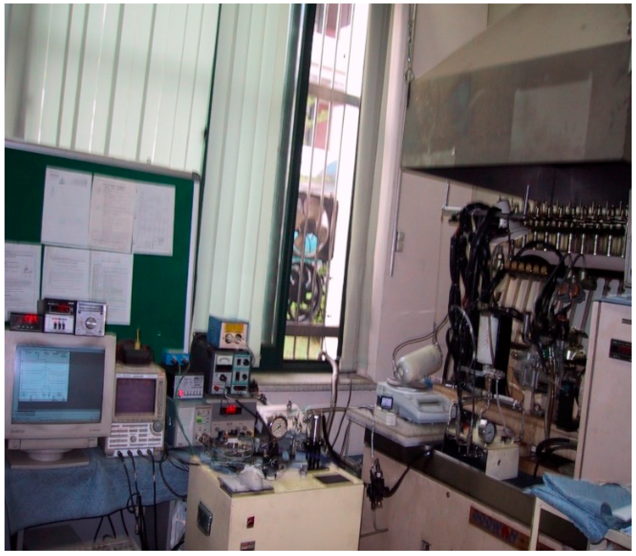
Figure 3.
Two-way valve control signals for fuel injection without pilot injection for DME and diesel.
Figure 3.
Two-way valve control signals for fuel injection without pilot injection for DME and diesel.
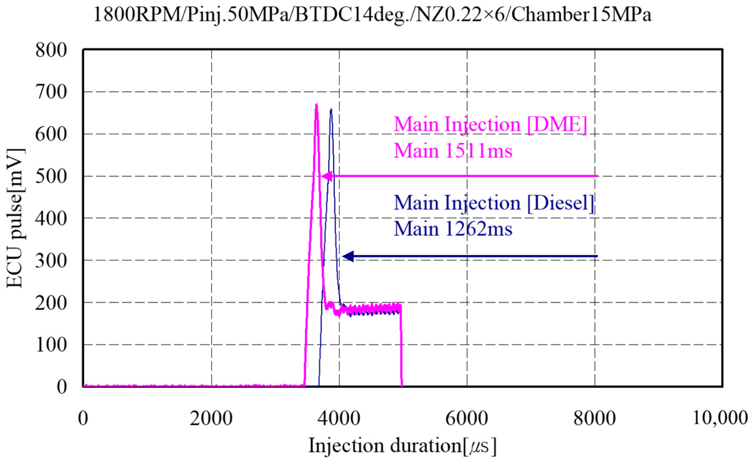
Figure 4.
Two-way valve control signals for fuel injection with pilot injection for DME and diesel.
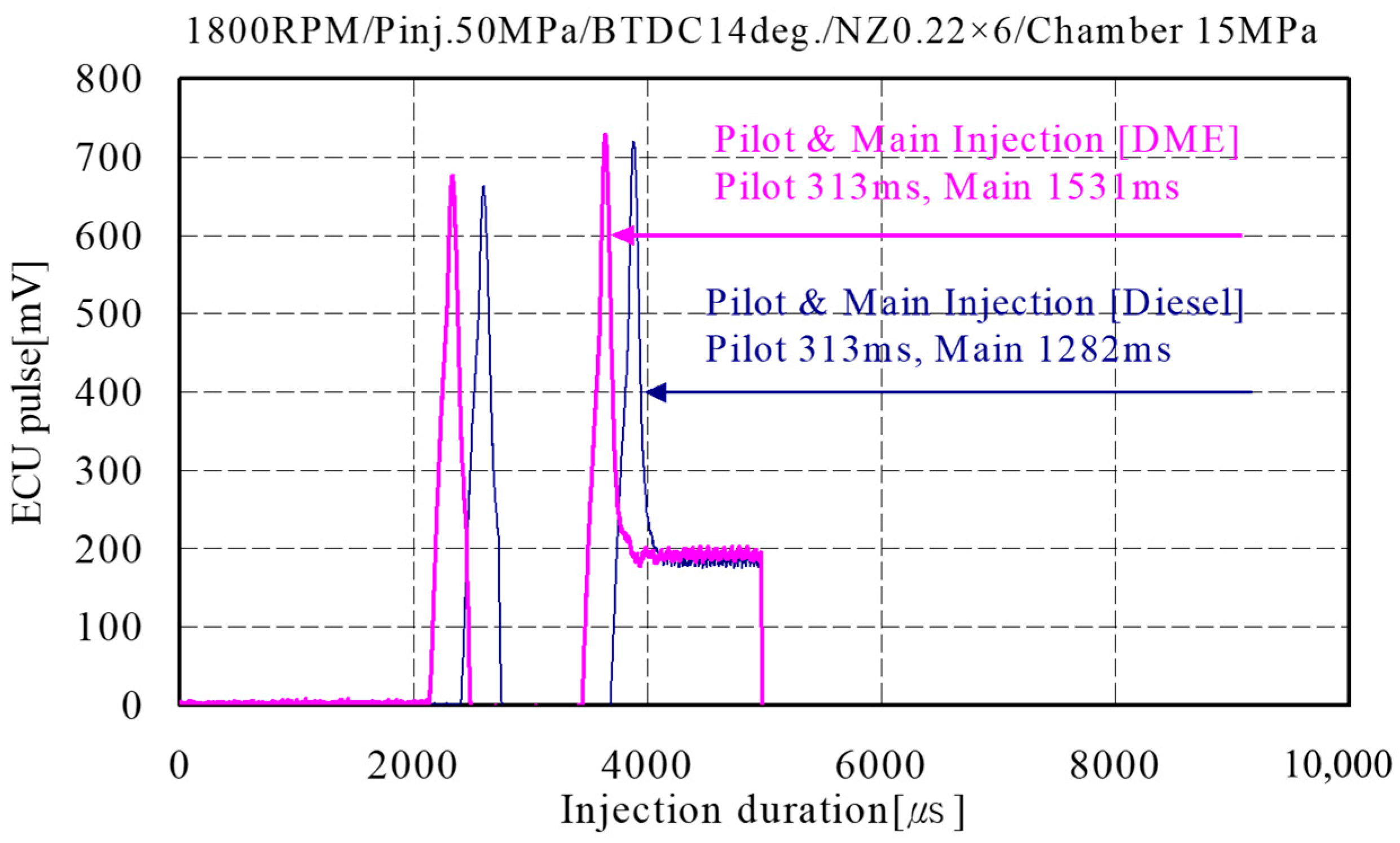
Figure 5.
Injection line pressure between the fuel rail and the injector as a function of the following: without pilot injection of the injection duration for diesel and DME.
Figure 5.
Injection line pressure between the fuel rail and the injector as a function of the following: without pilot injection of the injection duration for diesel and DME.

Figure 6.
Injection line pressure between the rail chamber and the injector as a function of the following: with pilot injection of the injection duration for diesel and DME.
Figure 6.
Injection line pressure between the rail chamber and the injector as a function of the following: with pilot injection of the injection duration for diesel and DME.

Figure 7.
Injection line pressure between the common rail and the injector as a function of the following: without pilot injection of the injection duration for diesel and DME.
Figure 7.
Injection line pressure between the common rail and the injector as a function of the following: without pilot injection of the injection duration for diesel and DME.

Figure 8.
Injection line pressure between the common rail and the injector as a function of the following: with pilot injection of the injection duration for diesel and DME.
Figure 8.
Injection line pressure between the common rail and the injector as a function of the following: with pilot injection of the injection duration for diesel and DME.

Figure 9.
Injection rate characteristic for the fuel injection with and without pilot injection of the injection duration for diesel and DME.
Figure 9.
Injection rate characteristic for the fuel injection with and without pilot injection of the injection duration for diesel and DME.

Figure 10.
Injection rate characteristic for only the pilot injection quantity of the pilot and main injection durations for DME.
Figure 10.
Injection rate characteristic for only the pilot injection quantity of the pilot and main injection durations for DME.

Figure 11.
Injection rate characteristic for only the main injection quantity of the pilot and main injection durations for DME.
Figure 11.
Injection rate characteristic for only the main injection quantity of the pilot and main injection durations for DME.

Figure 12.
Injection rate characteristic for only the pilot injection quantity of the pilot and main injection durations for diesel.
Figure 12.
Injection rate characteristic for only the pilot injection quantity of the pilot and main injection durations for diesel.

Figure 13.
Injection rate characteristic for only the main injection quantity of the pilot and main injection durations for diesel.
Figure 13.
Injection rate characteristic for only the main injection quantity of the pilot and main injection durations for diesel.


Table 1.
Injection rate and quantity meter specifications.
| Instument | Items | Specifications |
|---|---|---|
| Rate meter | Max. pressure | 100 MPa |
| Pipe length | 6000 mm | |
| Quantity meter | Chamber volume | 1500 mm3 |
| Max. pressure | 5–25 MPa |
Table 2.
Properties of DME and diesel fuels.
| Division. | Unite | DME | Diesel |
|---|---|---|---|
| Liquid density | kg/m3 | 667 | 831 |
| Cetane number | >55 | 40–55 | |
| Octan number | - | - | |
| Chemical structure | (CH3)2O | - | |
| Stoich.A/F Rate | kg/kg | 9.0 | 14.6 |
| Boiling point (760 mmHg) | °C | −25 | 180/370 |
| C | wt % | 52.2 | 86 |
| H | wt % | 13 | 14 |
| O | wt % | 34.8 | 0 |
| Velocity of sound: a | m/s | 980 | 1330 |
| Kinematic viscosity (Liquid): V | cSt | <1 | 3 |
| Modulus of elasticity | N/m2 | 6.37 × 10⁸ | 1.49 × 10⁹ |
| Cavitation factor | K | 0.1 | 0.68 |
| Low calorific value(LCV) | MJ/kg | 28.8 | 42.7 |
| Ignition limite | λ | 0.34/ | 0.48/ |
| Vapor pressure | kPa | 530 | - |
| Mol.wt | g/mol | 46.069 | 170 |
| Autoignition temperature | °C | 235 | 250 |
| Maximum explosion pressure | Bar.m/ | 7.9 | - |
| Maximum laminar burning velocity | m/s | 0.54 | - |
| Liquid specific heat | kJ/kg·k | - | 2.2 |
| Gaseous specific heat | kJ/kg·k | 2.99 | 1.7 |
| Heat of vaporisation | kJ/kg | 467.23 | 300 |
Table 3.
DME common rail specifications.
| Items | Items | Specifications | Dimension |
|---|---|---|---|
| Supply pump | Gas booster | Bore × stroke (mm × mm) | ϕ 29 × 64 |
| Liquid pump | Bore × stroke (mm × mm) | ϕ 15 × 64 | |
| Injector | PVC | Solenoid (V) | 24 |
| Needle lift | Lift (mm) | 0.21 | |
| Injection hole | Diameter (mm) | ϕ 0.21 × 5 | |
| Common rail | Pressure (MPa) | 100 |
Table 4.
Experiment condition.
| Experimental Conditions | Control Specification |
|---|---|
| Pump revolution | 900 rpm |
| Pilot injection duration | 0.313 ms |
| Main inj. timing | BTDC 14° |
| Pilot inj. timing | BTDC 25° |
| Injection pressure | 50 MPa |
| Nozzle hole specification (Nozzle diameter × hole number) | ϕ 0.22 (mm) × 6 holes |
| Chamber pressure | 5–15 MPa |
© 2018 by the authors. Licensee MDPI, Basel, Switzerland. This article is an open access article distributed under the terms and conditions of the Creative Commons Attribution (CC BY) license (http://creativecommons.org/licenses/by/4.0/).
Share and Cite
MDPI and ACS Style
Yang, S.; Lee, C. Experimental Research on the Injection Rate of DME and Diesel Fuel in Common Rail Injection System by Using Bosch and Zeuch Methods. Energies 2018, 11, 273. https://doi.org/10.3390/en11020273
AMA Style
Yang S, Lee C. Experimental Research on the Injection Rate of DME and Diesel Fuel in Common Rail Injection System by Using Bosch and Zeuch Methods. Energies. 2018; 11(2):273. https://doi.org/10.3390/en11020273
Chicago/Turabian StyleYang, Seemoon, and Changhee Lee. 2018. "Experimental Research on the Injection Rate of DME and Diesel Fuel in Common Rail Injection System by Using Bosch and Zeuch Methods" Energies 11, no. 2: 273. https://doi.org/10.3390/en11020273
Note that from the first issue of 2016, this journal uses article numbers instead of page numbers. See further details here.