Analysis of the Scavenging Process of a Two-Stroke Free-Piston Engine Based on the Selection of Scavenging Ports or Valves


1
Sir Joseph Swan Centre for Energy Research, Newcastle University, Newcastle upon Tyne NE1 7RU, UK
2
School of Mechanical Engineering, Beijing Institute of Technology, Beijing 100081, China
*
Author to whom correspondence should be addressed.
Energies 2018, 11(2), 324; https://doi.org/10.3390/en11020324
Submission received: 1 December 2017
/
Revised: 12 January 2018
/
Accepted: 24 January 2018
/
Published: 2 February 2018
Abstract
:The free-piston engine generator (FPEG) is a linear energy conversion device with the objective of utilisation within a hybrid-electric automotive vehicle power system. In this research, the piston dynamic characteristics of an FPEG is compared with that of a conventional engine (CE) of the same size, and the difference in the valve timing is compared for both port scavenging type and valve scavenging type, with the exhaust valve closing timing is selected as the parameter. A zero-dimensional simulation model is developed in Ricardo WAVE software (2016.1), with the piston dynamics obtained from the simulation model in Matlab/SIMULINK (R2017a). For the CE and FEPG using scavenging ports, in order to improve its power output to the same level as that of a CE, the inlet gas pressure is suggested to be improved to above 1.2 bar, approximately 0.2 bar higher than that used for a CE. If a CE cylinder with exhaust valves is adopted or referred to during the development of an FPEG prototype, the exhaust valve is suggested to be closed earlier to improve its power output, and a higher intake pressure is also suggested if its output power is expected to be the same or higher than that of a CE.
1. Introduction
The free-piston engine (FPE) is a novel power device system, and the main difference from a conventional crankshaft engine is that the piston motion is linear and free to move between its dead centers [1,2]. For the FPEs, the elimination of the crankshaft system and the reduction of mechanical components significantly reduces the complexity of the engine [3]. This gives a number of advantages: the heat transfer losses and NOx generation are supposed to be reduced due to faster expansion stroke; the frictional losses should be reduced due to the simplified mechanism and the elimination of the piston side force in conventional reciprocating engines; potentially lower maintenance cost due to a compact design; and multi-fuel/combustion mode possibility due to a possibility of variable compression ratio [4].
The FPE system is known to be coupled with different loads, which include air compressors, hydraulic pumps, and electric generators [1,5,6,7]. In this research, the FPE connected with a linear electric generator (free-piston engine generator, FPEG) is selected for future application in hybrid-electric automotive vehicles. Combustion takes place alternatively in each chamber of the engine makes the translator reciprocate and the linear electrical generator converts parts of the mover’s kinetic energy into electricity, which will be stored and/or used by an external load [8]. The effective efficiency is estimated to be up to 46% (including friction losses) at a power output level of 23 kW, which shows promising results in terms of engine performance and emissions [9].
Different FPEG prototypes have been reported in the recent years. Successful single-cylinder single-piston FPEG systems have been reported [4,10,11,12]. Researchers at West Virginia University described the development of a spark ignited dual-cylinder dual-piston engine generator as well as a compression ignition prototype [13,14]. Meanwhile, dual-cylinder dual-piston configurations have also been developed by researchers from a European Commission-funded Free-Piston Energy Converter (FPEC) project, Czech Technical University, Sandia National Laboratory, Beijing Institute of Technology, Shanghai Jiaotong University, and Newcastle University [15,16,17,18,19,20,21].
Most of the reported FPEG prototypes employ a two-stroke thermodynamic process, and the gas exchange process is performed with intake/exhaust ports or valves [22]. The cylinders adopted in an FPEG prototype at this stage are mainly from commercial products, and the others are designed and manufactured with a commercial engine taken as a reference [21,23,24]. For a conventional two-stroke engine, the crank angle is used as feedback to decide the valve timing. On the other hand, for the FEPG, the valve timing cannot be decided according to the crank angle as that of the reciprocating engine due to the elimination of the crankshaft system. However, very little research has been undertaken to examine its scavenging process based on the selection of scavenging ports or valves.
Researchers at Beijing Institute of Technology investigated the scavenging process of an FPEG prototype using computational fluid dynamics [25]. A time-based numerical simulation program was developed in Matlab to describe the movement of the piston, and a parametric analysis was undertaken based on the simulation model. The influence of the engine effective stroke length, valve overlapping timing, system operating frequency, and intake pressure, etc. on the engine scavenging performance was discussed. From the simulation results, it was suggested that in order to obtain high scavenging and trapping efficiencies, a combination of high effective stroke length to bore ratio and long valve overlapping timing with low intake pressure should be employed [25].
The scavenging process of a two-stroke FPEG prototype was investigated by researchers from Sandia National Laboratories, aiming to improve its thermal efficiency and exhaust emissions [26]. The scavenging system was configured using computational fluid dynamics, 0/1 dimensional modelling, and single step parametric variations. Different design options were analysed and compared, including the application of loop, hybrid-loop, and uniflow scavenging methods, different charge delivery options, etc. Meanwhile, the intake/exhaust port arrangement, valve lift and valve timing setting, and charging pressure selection were adjusted and analysed. The computational results indicated that a stratified scavenging scheme employing a uniflow geometry supplied by a stable, low temperature/pressure charge should best optimise the engine efficiency and emissions characteristics [26].
In this research, the piston dynamic characteristics of an FPEG is compared with that of a conventional engine of the same size, and the difference in the valve timing is compared for both the port scavenging type and valve scavenging type, with the exhaust valve closing timing being selected as the parameter. A zero-dimensional simulation model is developed in Ricardo WAVE software, with the piston dynamics obtained from the simulation model in Matlab/SIMULINK. Engine performance with different intake pressures and various exhaust valve closing timings are predicted and analysed, aiming to provide guidance for the design and optimisation of the FPEG scavenging process with either scavenging ports or valves.
2. Fundamental Analysis
2.1. FPEG Configuration
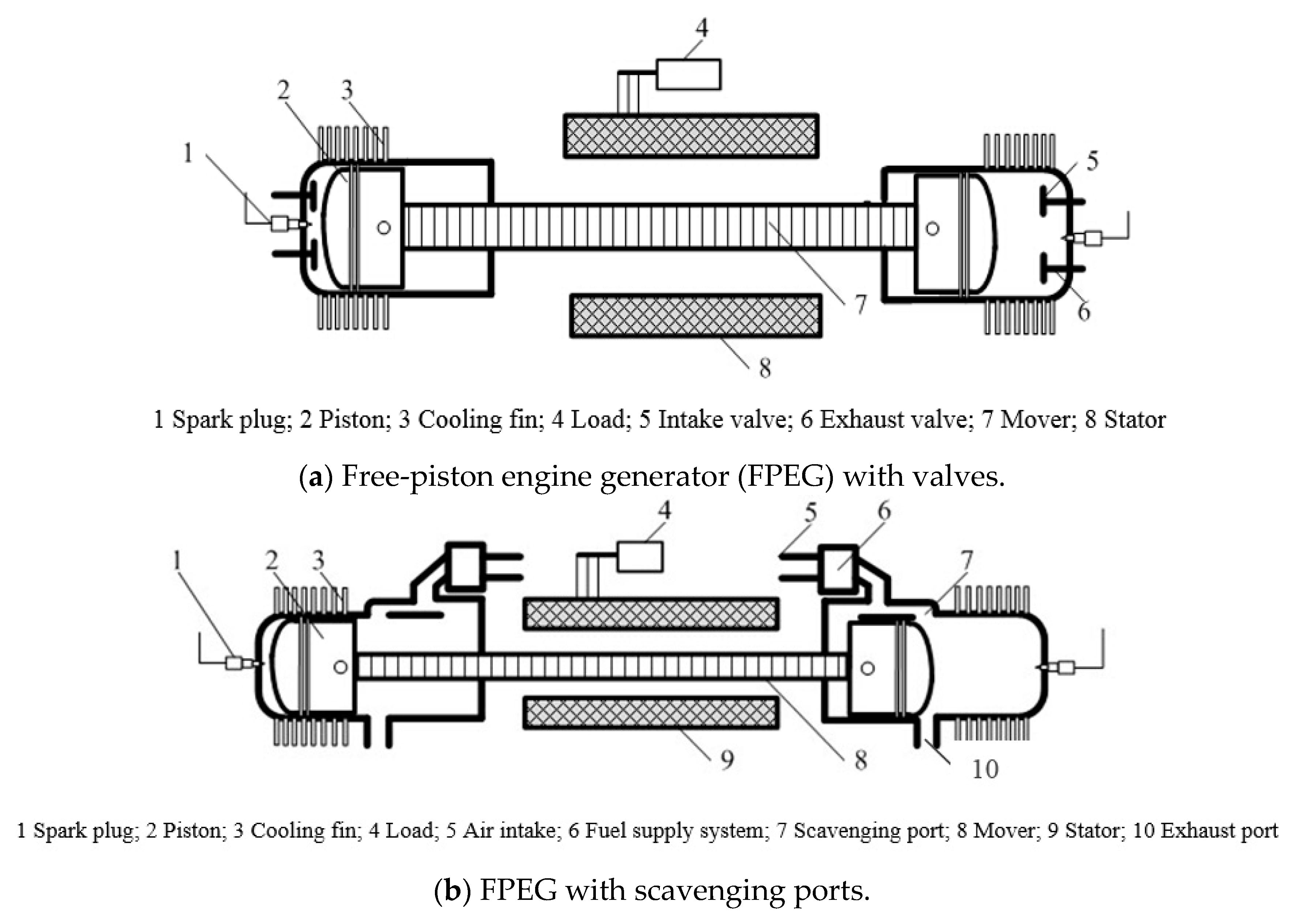
FPEGs can be divided into three categories according to piston/cylinder configuration: single-piston with single combustion cylinder, dual-piston with two combustion cylinders, and opposed-piston with a shared combustion cylinder [1]. The basic operation principles are the same for each concept; differences between the concepts include the number of combustion chambers and compression stroke realisation [27]. The FPEG prototype in this research adopts the most popular dual-piston type, the schematic configuration of which is shown in Figure 1. Figure 1a is an illustration for the FPEG with intake/exhaust valves, and Figure 1b is a demonstration of the FPEG with scavenging ports.
This FPEG comprises two internal combustion engines and a linear electric machine. The linear electric machine is located between the two cylinders, and the two pistons are connected with the mover. The spark-ignited FPEG employed here uses a two-stroke thermodynamic cycle, i.e., the power stroke is controlled to take place alternately in each cylinder, and to drive the compression stroke of the other cylinder. The pistons with the mover oscillate, and the linear electric generator converts part of the mechanical energy into electricity, which is stored by an external load.
2.2. Comparison of FPEG with a Conventional Engine (CE)
As the crankshaft mechanism is eliminated for an FPEG system, the piston movement is only affected by the forces acting on the pistons, as shown in Figure 2a. The main forces are the in-cylinder gas force from both cylinders, the resistance force from the linear electric machine, the mechanical frictional force, and the inertia of the moving mass. The corresponding dynamic equation is derived as:
where (unit: N) and (N) are the gas forces from the left and right cylinders respectively; (N) is the force output from the linear electric machine—a parameter which is varied depending if the machine is operated in motoring or generation modes; (N) is the mechanical friction force; (kg) is the moving mass of the piston assembly with the mover of the electric machine, and (m) is the piston distance from the cylinder head. The calculation of the forces mentioned above and model validation results can be found elsewhere [3,22,28].
For a conventional crank shaft engine, a schematic figure is shown in Figure 2b. The distance between the crank axis and the piston pin axis is given by [29]:
where is the connecting rod length (m); is the crank radius (m); and is the crank angle (degree).
As a result, the piston dynamics of an FPEG will be different from that of a conventional two-stroke crankshaft engine with the same size.
The cylinder volume at any crank position is:
where is the clearance volume (m3), and can be calculated from the swept volume and the set compression ratio :
The piston distance from the cylinder head of the crankshaft engine is then calculated by [29]:
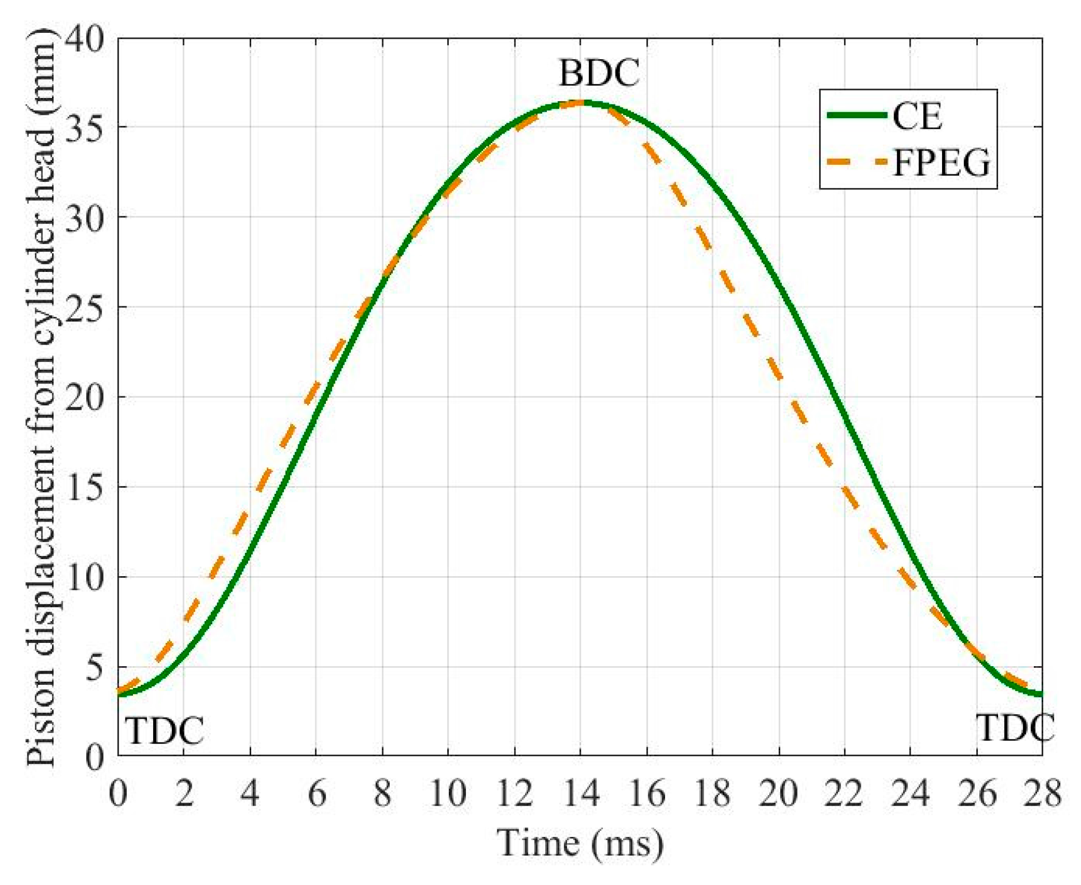
The engine of the FPEG is the same size as that of the CE. The specifications are summarised in Table 1. The input parameters for the FPEG is based on a prototype developed at Newcastle University, and a more detailed development process can be found elsewhere [21]. The piston diameter is the same for both engines. For the FPEG, the piston stroke is variable, and it is tuned to be the same as that of the CE by changing the input fuel and the electric load. The operation speed of the CE is set to be the same as that of the FPEG, which is 35.7 Hz for the FPEG, and 2142 rpm for the CE.
The simulated piston displacement from the cylinder head for the FPEG is demonstrated in Figure 3, with that of the CE shown in the same figure as a comparison. For a better understanding of the difference in piston dynamics, the changing trend of the piston velocity with the piston displacement is shown in Figure 4 with four specific points (points 1, 2, 3, 4) marked in the figure.
It can be found that the piston of the FPEG moves faster after combustion takes place (point 1 in Figure 4) as it is not restricted by the crankshaft system. For the FPEG, the expansion process is the corresponding compression process of the other cylinder, and the piston is driven by the combustion gas force to overcome the compression force. As a result, the piston velocity of the FPEG becomes slower soon after the top dead center (TDC) compared with that of the CE (point 2 in Figure 3). The peak velocity of the CE is approximately 4 m/s, which is higher than that achieved in the FPEG (around 3.4 m/s).
When the piston is moving towards the TDC from its bottom dead center (BDC), the piston velocity is higher in the FPEG at the beginning of the stroke (point 3 in Figure 4), while gets slower afterward (point 4 in Figure 4). The piston velocity at point 3 in Figure 4 is higher because the piston is driven by the high-pressure gas after combustion. As the FPEG configuration employed in this research is a dual-piston type, the compression process (from BDC to TDC) is the corresponding expansion process for the cylinder of the other side. Without the crankshaft mechanism, the piston velocity will be lower when the piston is approaching its TDC during the compression process.
2.3. Valve Opening Timing
The cylinders adopted in an FPEG prototype at this stage are mainly from commercial products, and the others are designed and manufactured with a commercial engine taken as a reference. The scavenging process is performed by ports and valves. If a scavenging port is used, it is covered/uncovered by the piston movement. If valves are employed, then the scavenging process is controlled by opening/closing the valve. For a conventional two-stroke engine, the crank angle is used as feedback to decide the valve timing. In contrast, for the FEPG, the valve timing cannot be decided according to the crank angle as that of the reciprocating engine due to the elimination of the crankshaft system. In order to make further comparison of the FPEG with CE, an equivalent crank angle (ECA) is adopted for the FPEG to describe one operation cycle [3]:
where is the operation time (s) and is the operation duration for one cycle.
The piston displacement with the crank angle for the CE, or the ECA for the FPEG, is compared in Figure 5 and Figure 6. If the FPEG uses the same engine as the CE, then difference in the valve timing will be compared for both port scavenging type and valve scavenging type. The exhaust valve closing (EVC) timing is a crucial parameter that can affect the scavenging efficiency and the compression stroke length, etc. Meanwhile, the difference in piston displacement is more significant when the piston is moving from its BDC to TDC for the CE and FPEG. As a result, the EVC timing is selected as the parameter to compare the valve timing of the CE and the FPEG.
For the CE and FPEG engines using scavenging ports, the ports will be opened/closed when the piston reaches a certain position. The valve timing can be adjusted during the design process, while it cannot be varied during the operation. If a reference EVC is set to be 32 mm from the cylinder head, then the EVC for the FPEG is approximately 10° earlier than that of the CE. As a result, the scavenging efficiency and trapping efficiency will be affected if an early EVC or short scavenging process is adopted.
If a valve scavenging type engine is adopted for both the CE and the FPEG, the valve timing can be adjusted during the operation process with the crank angle. If the exhaust valve is set to close 50° after BDC, as illustrated in Figure 6, the compression stroke of the FPEG will be reduced (around 4 mm shorter than that of the CE). As a result, the peak cylinder pressure and the corresponding engine-indicated work is expected to be lower, which will then reduce the engine thermal efficiency and the whole system efficiency.
2.4. Simulation Methodology
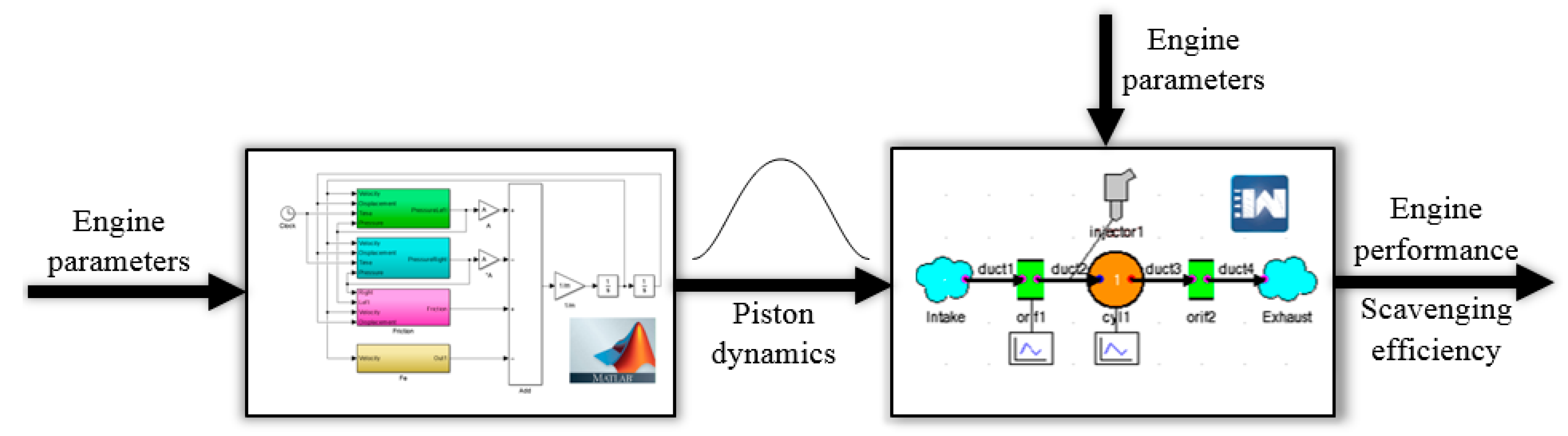
In order to investigate the scavenging performance of the FPEG and further optimise its valve timing, a zero-dimensional simulation model is developed in Ricardo WAVE software, with the piston dynamics obtained from the simulation model of the FEPG and the CE in Matlab/SIMULINK. The simulation process is illustrated in Figure 7. The simulation model in WAVE is a two-stroke single-cylinder engine, and the piston motion profile is imported from the simulation results in Matlab/SIMULINK. The piston motion profile of the FPEG is described with crank angle using Equation (6).
The other engine input parameters for the model are summarised in Table 2. The parameters in Table 2 are kept unchanged during the simulation for both the FPEG and the CE. The output from the simulation model in WAVE would be the engine performance, e.g., cylinder pressure, power output, scavenging efficiency, etc. The ignition timings of the FPEG and the CE are set to be the same, which is 15° before top dead centre (bTDC). The simulation in this research aims to provide the following information for the future design and optimisation of the FPEG scavenging process:
- (a)
- If an engine with scavenging ports is adopted for the FPEG prototype, information on the performance of the scavenging process, the difference compared to that of the CE with the same cylinder, and the methods to improve the system scavenging process are collected.
- (b)
- If an engine with valves is adopted for the FPEG prototype, information on how the valve timing will affect its scavenging process, the difference compared to that of the CE with the same cylinder, and the optimised valve timing are collected.
3. Results and Discussion
3.1. FPEG with Scavenging Ports
For the CE and FEPG using scavenging ports, and the EVC timing is set to be 32 mm from the cylinder head, as illustrated in Figure 5, and the inlet gas pressure is 1.2 bar. The cylinder pressure is shown in Figure 8, and the cylinder pressures with the volume/clearance volume for both engine types are compared in Figure 9. The other input parameters are the same for the CE and FPEG. As a result, the peak cylinder pressure of the CE is approximately 41 bar, which is 7 bar higher than that of the FPEG (34 bar), even though the same compression stroke length is adopted for both of the engines. The peak value is obtained after the piston reaches its TDC. The pressure of the FPEG at the end of the compression process is also lower than that of the CE. As the free-piston is not limited by the mechanical system, its velocity after TDC is higher than that of CE (as shown in Figure 4), and the corresponding cylinder pressure is lower due to a faster expansion process. When the exhaust port opens, the cylinder pressure is nearly the same for both engines.
The scavenging efficiency for the FPEG is 94.1%, which is slightly lower than that of the CE (94.8%). For the engine output power, the power of the FPEG is supposed to be much lower than that of the CE. As can be seen from Figure 9, the area enclosed by the pressure-volume of the FPEG is less than that of the CE. From the calculated results of the WAVE software, the brake power of the single-cylinder CE engine is 2.1 kW, and that of a single-cylinder FPEG is 1.7 kW, with the same engine size and operation speed.
For the engine with scavenging ports, the opening/closing timing of the ports is controlled by the piston movement. It can be adjusted during the design process, while it cannot be varied during engine operation. If the FPEG adopts a commercial cylinder with scavenging ports, the opening/closing positions of the ports are fixed. As a result, the engine scavenging efficiency and power output of the FEPG will be affected, and the performance is not as good as that in a CE. Generally, for a CE and an FPEG with the design parameters shown in Table 1 and Table 2, a compressor for inlet gas pressure increase is suggested to boost the pressure to above 1.2 for a better scavenging performance. The system scavenging efficiency with different inlet gas pressures for both the CE and FPEG is compared in Figure 10.
The engine-indicated power and peak pressure of both the CE and FPEG with different inlet gas pressures are shown in Figure 11. The engine efficiency is supposed to show a similar trend compared to the engine-indicated power output due to the setting of the fuel injection. It is found that if the FPEG shares the same cylinder size and scavenging ports position with the CE, then the peak cylinder gas pressure and output brake power of the CE is higher than that of the FPEG, with an inlet gas pressure range of 1.1–2.0 bar. However, by increasing the inlet gas pressure, both the peak cylinder gas pressure and the engine output brake power increase in a nearly linear relationship. The potential reasons for this could be that more air and fuel is drawn to the cylinder with higher inlet gas pressure (the fuel injector is a proportional type, which means the fuel mass is proportional to the inlet air mass), and thus the scavenging efficiency is improved. As a result, for an FPEG prototype of this kind, in order to improve its power output to the same level as that of a CE with the same size, the inlet gas pressure is suggested to be improved by approximately 0.2 bar compared to that used for a CE. Meanwhile, the intake pressure of the FPEG is suggested to be boosted to above 1.4 bar for a better power output.
3.2. FPEG with Valves
If a cylinder with exhaust valves is adopted to during the development of an FPEG prototype, the exhaust valve will be set to close at 50° after BDC (or 230° from TDC), as illustrated in Figure 6. The cylinder pressure vs the volume/clearance volume profiles for both engines are compared in Figure 12. The input gas pressure is set to 1.2 bar for both engines, and all of the input parameters except for the exhaust valve closing timing are identical. It is found that the peak cylinder pressure, the area enclosed by the p-V diagram, and the corresponding engine-indicated work of the FPEG are lower than that of the CE, as the compression stroke of the FPEG is reduced. As a result, if an FPEG prototype uses the same cylinder as the CE without adjusting the exhaust valve closing angle, the peak cylinder pressure will be reduced by approximately 10 bar and the engine output brake power will be affected by 0.4 kW.
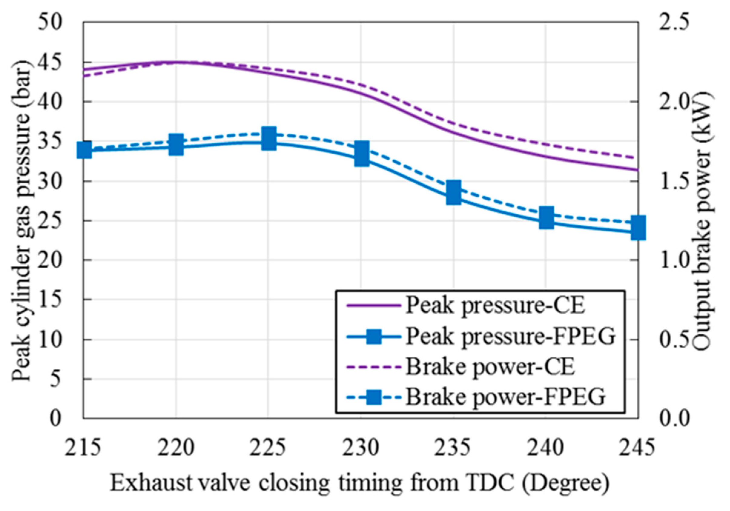
The engine-indicated power and peak pressure with different EVC timings are compared and shown in Figure 13. As the fuel injection is fixed for each operating cycle, the engine efficiency is supposed to show a similar trend compared to that of the output brake power. It is found that for both the CE and FPEG, the peak cylinder pressure and output brake power decrease when a late exhaust valve closing timing is employed. For the CE, the maximum brake power is achieved when the exhaust valve closes at 220°; while for the FPEG it is reached at 225°. With the same exhaust valve closing timing, the peak cylinder pressure and power achieved by the FPEG are always approximately 0.4 kW lower than that of the CE, due to a shorter compression stroke. As a result, for an FPEG prototype with valves, the exhaust valve is suggested to be closed earlier to improve its power output (but no earlier than 225°). However, a higher intake pressure is also suggested if its output power is expected to be the same or even higher than that of a CE. Meanwhile, the EVC timing is not considered useful to control power output for the FPEG as the improvement is very low, while boosting the intake pressure is overwhelmingly better than changing the EVC timing.
4. Conclusions
In this research, the piston dynamic characteristics of an FPEG is compared with that of a conventional engine of the same size, and the difference in the valve timing is compared for both port scavenging type and valve scavenging type, with the exhaust valve closing timing selected as the parameter. It should be noted that the current state-of-study is still in early stages, and a roadmap in research ought to be mentioned. Main conclusions and suggestions from this research are listed below:
- (1)
- Compared with a CE, the piston of the FPEG moves faster after combustion takes place, as it is not restricted by the crankshaft system, while becomes slower soon after this. The piston velocity of an FPEG will be lower when the piston is approaching its TDC during the compression process, and the peak velocity achieved is also lower than that of a CE.
- (2)
- For the CE and FEPG using scavenging ports with the EVC timing set to be 32 mm from the cylinder head, the peak cylinder pressure, engine power output, and scavenging efficiency of the FEPG are found to be lower than that of a CE with the same size and operation conditions. For an FPEG prototype of this kind, in order to improve its power output to the same level as that of a CE with the same size, the inlet gas pressure is suggested to be improved to above 1.4 bar for a better power output, which is approximately 0.2 bar higher than that used for a CE.
- (3)
- If a CE cylinder with exhaust valves is adopted or referred to during the development of an FPEG prototype, and the exhaust valve is set to close at 50° after BDC, the engine-indicated work of the FPEG are found to be lower than that of the CE as the compression stroke of the FPEG is reduced. For an FPEG prototype with valves, the exhaust valve is suggested to be closed earlier to improve its power output (but no earlier than 225°), and a higher intake pressure is also suggested if its output power is expected to be the same or higher than that of a CE. Meanwhile, the EVC timing is not considered useful to control power output for the FPEG as the improvement is very low, while boosting the intake pressure is overwhelmingly better than changing the EVC timing.
Acknowledgments
This work was funded using the EPSRC (Engineering and Physical Sciences Research Council) Impact Acceleration Account (EP/K503885/1) and Thermal Energy Challenge Network (EP/P005667/1). Data supporting this publication is openly available under an ‘Open Data Commons Open Database License’. Additional metadata are available at: http://dx.doi.org/10.17634/123306-4. Please contact Newcastle Research Data Service at [email protected] for access instructions.
Author Contributions
Yaodong Wang and Boru Jia proposed the topic and methodology; Boru Jia and Andrew Smallbone developed the simulation model and analyzed the data; Boru Jia wrote the paper; Anthony Paul Roskilly contributed analysis tools and revised the paper.
Conflicts of Interest
The authors declare no conflict of interest.
References
- Mikalsen, R.; Roskilly, A.P. A review of free-piston engine history and applications. Appl. Therm. Eng. 2007, 27, 2339–2352. [Google Scholar] [CrossRef]
- Zhao, Z.; Zhang, F.; Huang, Y.; Zhao, C. Determination of TDC in a hydraulic free-piston engine by a novel approach. Appl. Therm. Eng. 2014, 70, 524–530. [Google Scholar] [CrossRef]
- Jia, B.; Smallbone, A.; Zuo, Z.; Feng, H.; Roskilly, A.P. Design and simulation of a two-or four-stroke free-piston engine generator for range extender applications. Energy Convers. Manag. 2016, 111, 289–298. [Google Scholar] [CrossRef]
- Goto, S.; Moriya, K.; Kosaka, H.; Akita, T.; Hotta, Y.; Umeno, T.; Nakakita, K. Development of Free Piston Engine Linear Generator System Part 2—Investigation of Control System for Generator; SAE Technical Paper; SAE International: Detroit, MI, USA, 2014. [Google Scholar]
- Tikkanen, S.; Vilenius, M. On the dynamic characteristics of the hydraulic free piston engine. In Proceedings of the ICMA’98: International Conference on Machine Automation, Tampere, Finland, 15–18 September 1998. [Google Scholar]
- Achten, P.A.; van den Oever, J.P.; Potma, J.; Vael, G.E. Horsepower with Brains: The Design of the Chiron Free Piston Engine; SAE Technical Paper; SAE International: Milwaukee, WI, USA, 2000. [Google Scholar]
- Van Blarigan, P.; Paradiso, N.; Goldsborough, S. Homogeneous Charge Compression Ignition with a Free Piston: A New Approach to Ideal Otto Cycle Performance; SAE Technical Paper; SAE International: San Francisco, CA, USA, 1998. [Google Scholar]
- Jia, B.; Mikalsen, R.; Smallbone, A.; Zuo, Z.; Feng, H.; Roskilly, A.P. Piston motion control of a free-piston engine generator: A new approach using cascade control. Appl. Energy 2016, 179, 1166–1175. [Google Scholar] [CrossRef]
- Max, E. FPEC, Free piston energy converter. In Proceedings of the 21st Electric Vehicle Symposium & Exhibition, EVS, Monaco, France, 2–6 April 2005. [Google Scholar]
- Haag, J.; Kock, F.; Chiodi, M.; Mack, O.; Bargende, M.; Naumann, C.; Slavinskaya, N.; Heron, A.; Riedel, U.; Ferrari, C. Development Approach for the Investigation of Homogeneous Charge Compression Ignition in a Free-Piston Engine. Available online: https://doi.org/10.4271/2013-24-0047 (accessed on 25 January 2018).
- Kosaka, H.; Akita, T.; Moriya, K.; Goto, S.; Hotta, Y.; Umeno, T.; Nakakita, K. Development of Free Piston Engine Linear Generator System Part 1-Investigation of Fundamental Characteristics. Available online: https://doi.org/10.4271/2014-01-1203 (accessed on 25 January 2018).
- Kock, F.; Haag, J.; Friedrich, H.E. The Free Piston Linear Generator-Development of an Innovative, Compact, Highly Efficient Range-Extender Module. Available online: https://doi.org/10.4271/2013-01-1727 (accessed on 25 January 2018).
- Nandkumar, S. Two-Stroke Linear Engine; West Virginia University: Morgantown, WV, USA, 1998. [Google Scholar]
- Houdyschell, D. A Diesel Two-Stroke Linear Engine; West Virginia University: Morgantown, WV, USA, 2000. [Google Scholar]
- Hansson, J. Analysis and Control of a Hybrid Vehicle Powered by Free-Piston Energy Converter. Ph.D. Thesis, Kungliga Tekniska Hogskolan, Stockholm, Sweden, 2006. [Google Scholar]
- Johnson, T.A.; Leick, M.T. Experimental Evaluation of the Free Piston Engine—Linear Alternator (FPLA); Sandia National Laboratories: Albuquerque, NM, USA, 2015. [Google Scholar]
- Vysoký, O. Linear Combustion Engine as Main Energy Unit for Hybrid Vehicles; Proceedings of Transtec Prague; Czech Technical University: Prague, Czech Republic, 2007; pp. 236–244. [Google Scholar]
- Feng, H.; Guo, C.; Jia, B.; Zuo, Z.; Guo, Y.; Roskilly, T. Research on the intermediate process of a free-piston linear generator from cold start-up to stable operation: Numerical model and experimental results. Energy Convers. Manag. 2016, 122, 153–164. [Google Scholar] [CrossRef]
- Miao, Y.; Zuo, Z.; Feng, H.; Guo, C.; Song, Y.; Jia, B.; Guo, Y. Research on the Combustion Characteristics of a Free-Piston Gasoline Engine Linear Generator during the Stable Generating Process. Energies 2016, 9, 655. [Google Scholar] [CrossRef]
- Li, Q.; Xiao, J.; Huang, Z. Simulation of a two-stroke free-piston engine for electrical power generation. Energy Fuels 2008, 22, 3443–3449. [Google Scholar] [CrossRef]
- Hanipah, M.R. Development of a Spark Ignition Free-Piston Engine Generator. Ph.D. Thesis, Newcastle University, Newcastle upon Tyne, UK, 2015. [Google Scholar]
- Jia, B.; Zuo, Z.; Tian, G.; Feng, H.; Roskilly, A.P. Development and validation of a free-piston engine generator numerical model. Energy Convers. Manag. 2015, 91, 333–341. [Google Scholar] [CrossRef]
- Mao, J.; Zuo, Z.; Feng, H. Parameters coupling designation of diesel free-piston linear alternator. Appl. Energy 2011, 88, 4577–4589. [Google Scholar] [CrossRef]
- Mao, J.; Feng, H.; Zuo, Z. Dimensionless Parametric Analysis of Spark Ignited Free-Piston Linear Alternator. Available online: https://www.intechopen.com/books/thermodynamics-interaction-studies-solids-liquids-and-gases/dimensionless-parametric-analysis-of-spark-ignited-free-piston-linear-alternator (accessed on 25 January 2018).
- Mao, J.; Zuo, Z.; Li, W.; Feng, H. Multi-dimensional scavenging analysis of a free-piston linear alternator based on numerical simulation. Appl. Energy 2011, 88, 1140–1152. [Google Scholar] [CrossRef]
- Goldsborough, S.S.; van Blarigan, P. Optimizing the Scavenging System for a Two-Stroke Cycle, Free Piston Engine for High Efficiency and Low Emissions: A Computational Approach. Available online: https://doi.org/10.4271/2003-01-0001 (accessed on 25 January 2018).
- Aichlmayr, H.T. Design Considerations, Modeling, and Analysis of Micro-Homogeneous Charge Compression Ignition Combustion Free-Piston Engines. Ph.D. Thesis, University of Minnesota, Minneapolis, MN, USA, 2002. [Google Scholar]
- Jia, B.; Smallbone, A.; Feng, H.; Tian, G.; Zuo, Z.; Roskilly, A.P. A fast response free-piston engine generator numerical model for control applications. Appl. Energy 2016, 162, 321–329. [Google Scholar] [CrossRef]
- Heywood, J.B. Internal Combustion Engine Fundamentals; Mcgraw-hill New York: New York, NY, USA, 1988; Volume 930. [Google Scholar]
Figure 1.
FPEG schematic configuration [3].
Figure 1.
FPEG schematic configuration [3].

Figure 2.
Schematic figures of an FPEG and a conventional engine (CE).
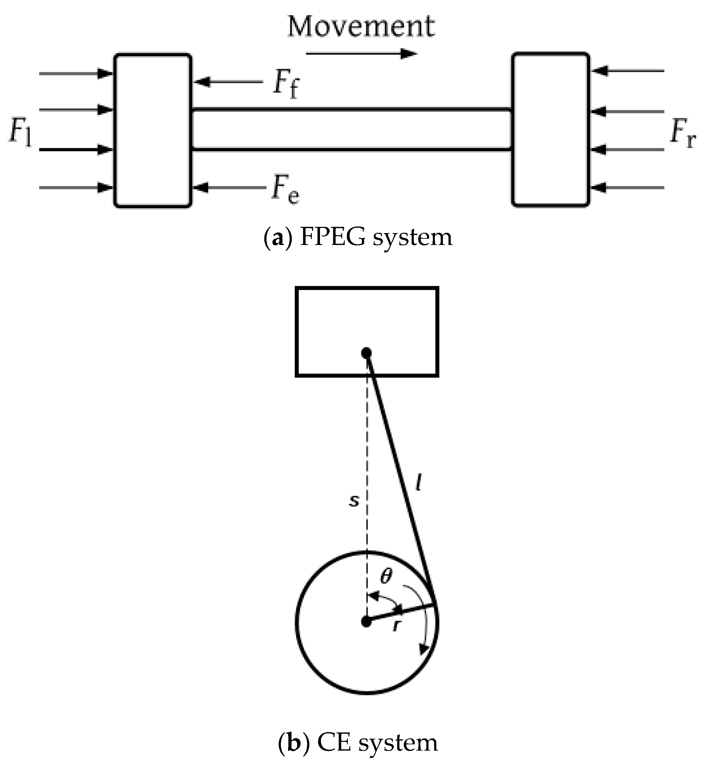
Figure 3.
Comparison of FPE and CE piston displacement.

Figure 4.
Comparison of FPEG and CE piston velocity.
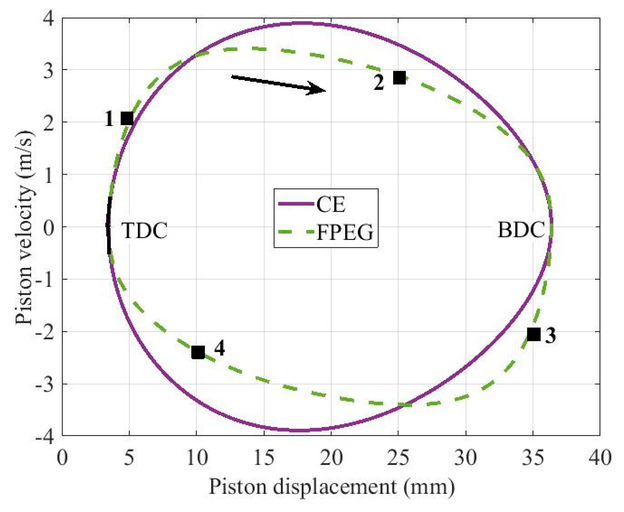
Figure 5.
Valve timing of CE and FPEG with port scavenging type.
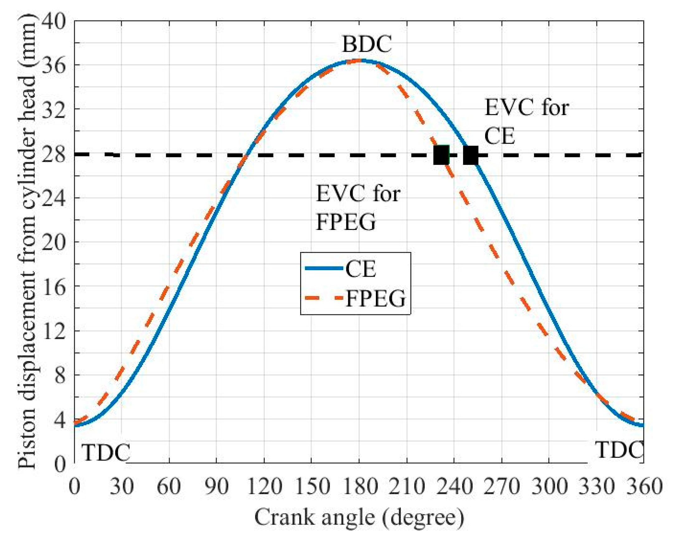
Figure 6.
Valve timing of CE and FPEG with valve scavenging type.
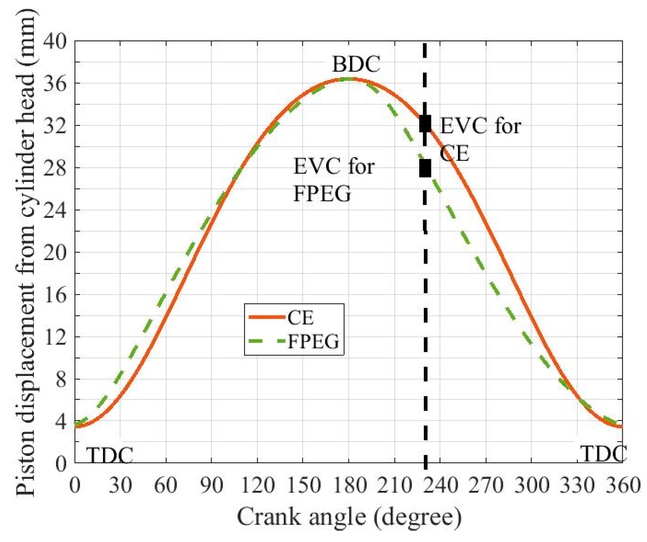
Figure 7.
Simulation process.

Figure 8.
Cylinder pressure for the CE and FPEG with scavenging ports.
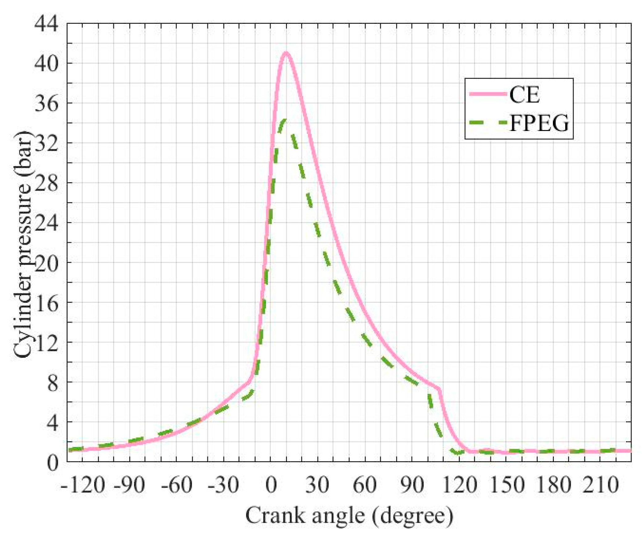
Figure 9.
p-V diagram of FPEG with scavenging ports compared with CE.
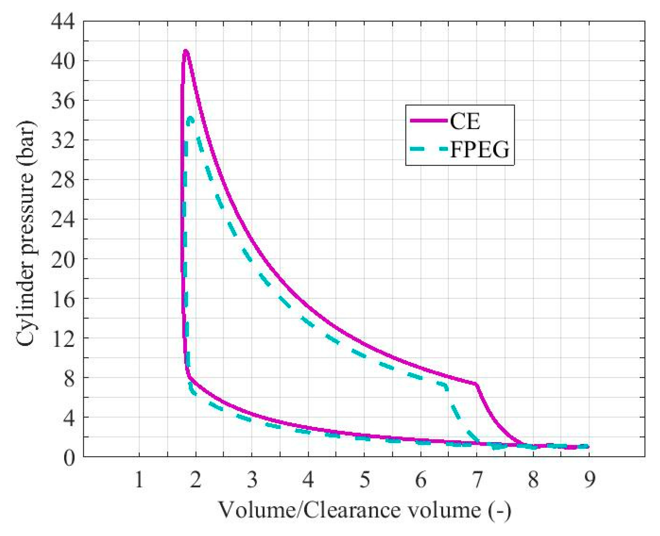
Figure 10.
Scavenging efficiency with different intake pressures.
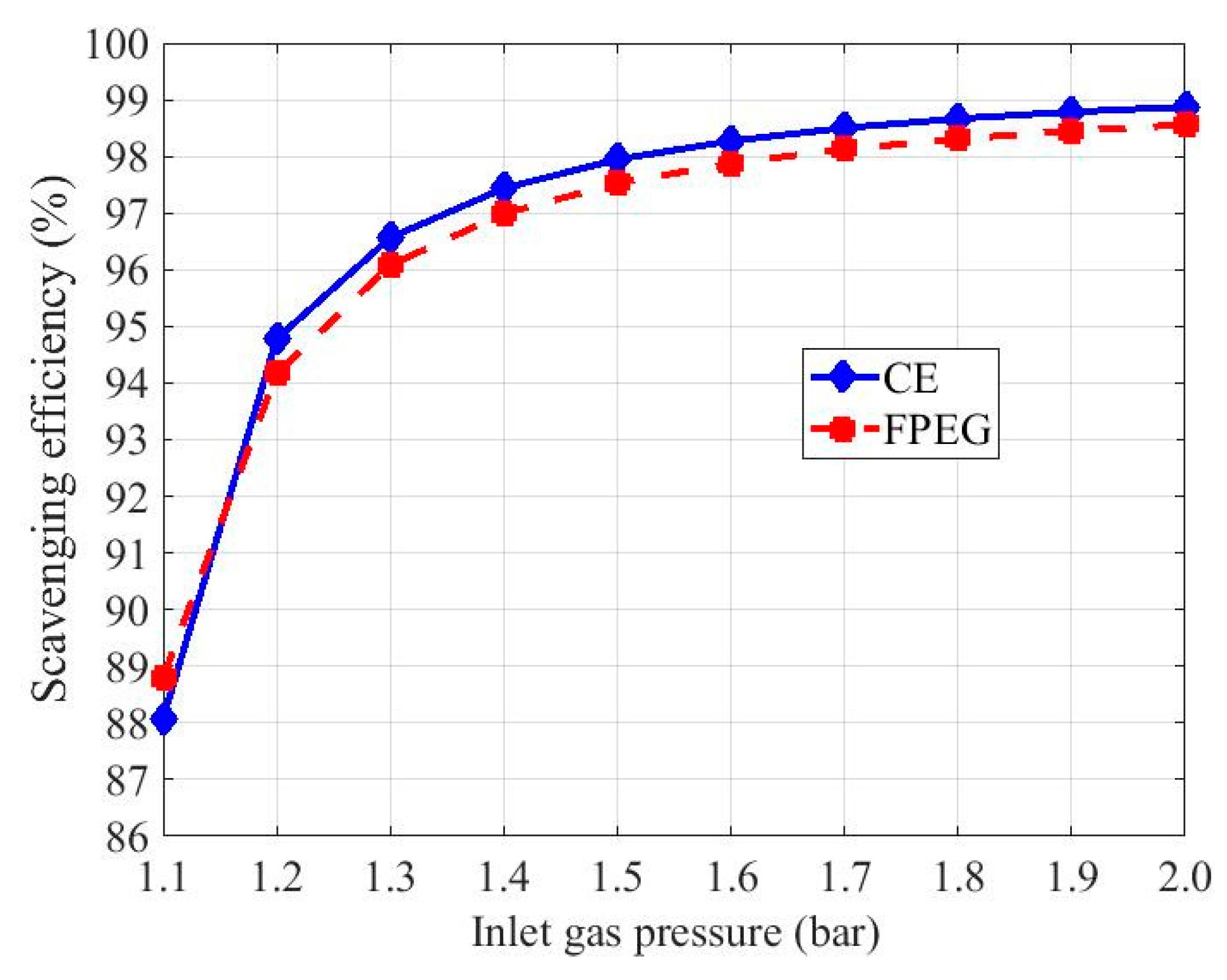
Figure 11.
Engine-indicated power and peak pressure with different intake pressures.
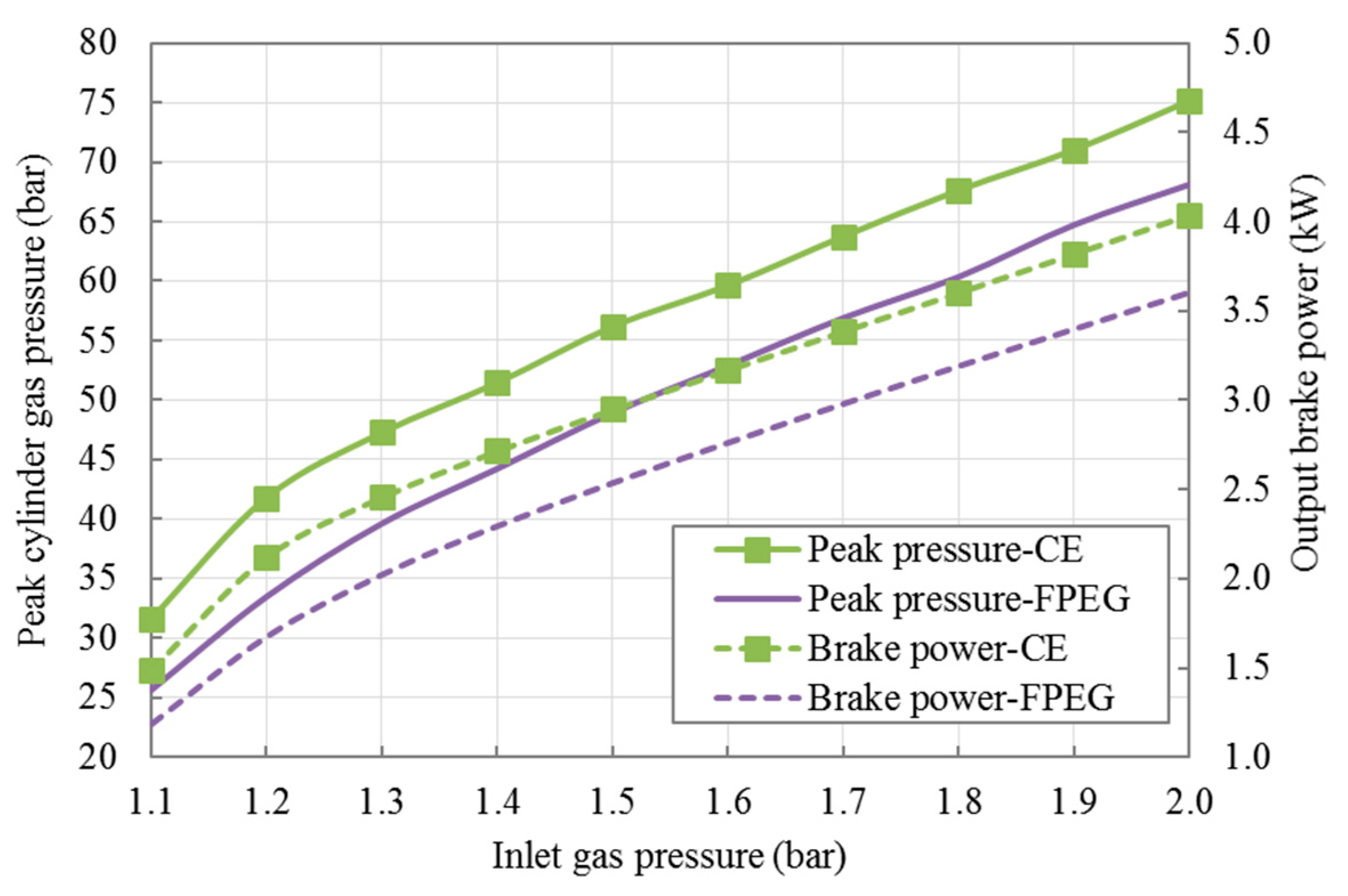
Figure 12.
p-V diagram of FPEG and CE with the same valve timing.
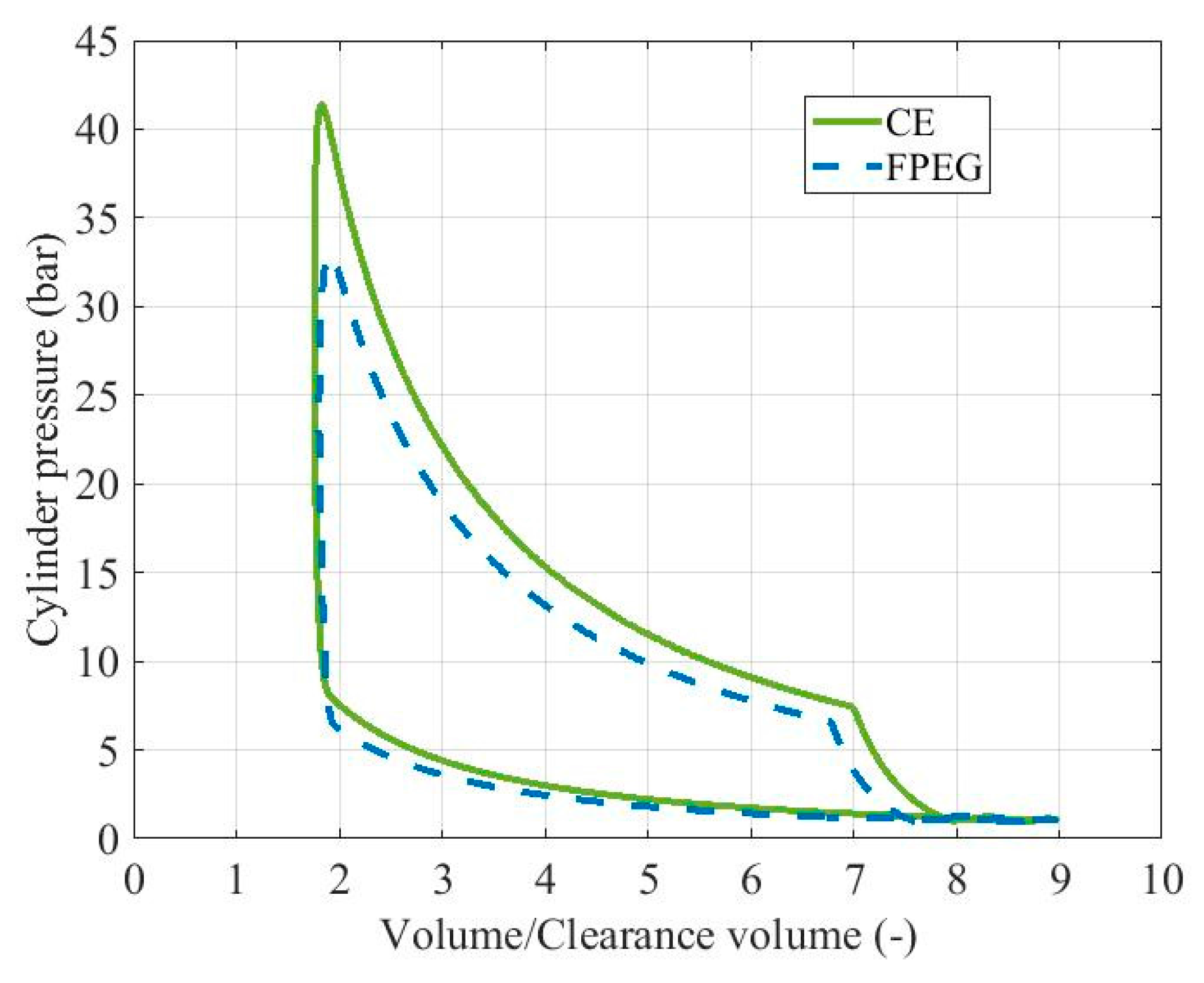
Figure 13.
Engine-indicated power and peak pressure with different exhaust valve closing (EVC) timings.
Figure 13.
Engine-indicated power and peak pressure with different exhaust valve closing (EVC) timings.


Table 1.
Specifications of FPEG and CE.
| Parameters (Unit) | FPEG | CE |
|---|---|---|
| Piston diameter (mm) | 50.0 | 50.0 |
| Stroke (mm) | 33.0 | 33.0 |
| Compression ratio (-) | 10.5 | 10.5 |
| Connecting rod length (mm) | - | 49.5 |
| Crank radius (mm) | - | 16.5 |
Table 2.
Simulation engine input parameters.
| Parameters (Unit) | Value |
|---|---|
| Engine speed (rpm) | 2143 |
| Number of valves (-) | 2 |
| Intake valve diameter (mm) | 18.0 |
| Exhaust valve diameter (mm) | 18.0 |
| Valve lift (mm) | 4.2 |
| Fuel type (-) | Octane |
| Fuel lower heating valve (J/kg) | 4.4 × 10⁷ |
| Air fuel ratio (-) | 14.7 |
| Intake air pressure (bar) | 1.0–2.0 |
| Intake air temperature (K) | 300.0 |
| Ignition timing (°) | 15 bTDC |
© 2018 by the authors. Licensee MDPI, Basel, Switzerland. This article is an open access article distributed under the terms and conditions of the Creative Commons Attribution (CC BY) license (http://creativecommons.org/licenses/by/4.0/).
Share and Cite
MDPI and ACS Style
Jia, B.; Wang, Y.; Smallbone, A.; Roskilly, A.P. Analysis of the Scavenging Process of a Two-Stroke Free-Piston Engine Based on the Selection of Scavenging Ports or Valves. Energies 2018, 11, 324. https://doi.org/10.3390/en11020324
AMA Style
Jia B, Wang Y, Smallbone A, Roskilly AP. Analysis of the Scavenging Process of a Two-Stroke Free-Piston Engine Based on the Selection of Scavenging Ports or Valves. Energies. 2018; 11(2):324. https://doi.org/10.3390/en11020324
Chicago/Turabian StyleJia, Boru, Yaodong Wang, Andrew Smallbone, and Anthony Paul Roskilly. 2018. "Analysis of the Scavenging Process of a Two-Stroke Free-Piston Engine Based on the Selection of Scavenging Ports or Valves" Energies 11, no. 2: 324. https://doi.org/10.3390/en11020324
Note that from the first issue of 2016, this journal uses article numbers instead of page numbers. See further details here.