Device Performance Improvement of Recycling Double-Pass Cross-Corrugated Solar Air Collectors

Energy and Opto-Electronic Materials Research Center, Department of Chemical and Materials Engineering, Tamkang University, Tamsui, New Taipei 251, Taiwan
*
Author to whom correspondence should be addressed.
Energies 2018, 11(2), 338; https://doi.org/10.3390/en11020338
Submission received: 28 December 2017
/
Revised: 24 January 2018
/
Accepted: 24 January 2018
/
Published: 2 February 2018
Abstract
:The device performance of cross-corrugated double-pass solar air heaters under external recycle conditions was investigated experimentally and theoretically, and solved numerically using the Newton method. Comparisons were made and represented graphically among three different configurations of the single-pass, flat-plate double-pass and cross-corrugated double-pass devices. Air flowing simultaneously over the wavelike corrugated absorbing plate and in-between both wavelike cross-corrugated absorbing and transverse bottom plates was conducted under double-pass operations. A considerable heat-transfer efficiency enhancement is obtained employing such a recycling double pass device with welding cross-corrugated absorbing plates, instead of using the flat-plate device. An effective thermal performance was achieved because the heat transfer area is doubled and the turbulent intensity is enhanced as well. The power consumption increment owing to the reduction in the cross-sectional area was taken into account associated with the heat-transfer efficiency enhancement for comparisons in determining the optimal design on an economic consideration for the recycling cross-corrugated double-pass device.
1. Introduction
Absorbing distant solar radiation to convert it into thermal energy as a heating resource has attracted a great deal of interest in recent years. One of the most cost-effective devices in low temperature (less than 100 °C) energy applications is the solar air collector, and its simplest form for accomplishing the energy transformation is the flat-plate solar collector widely used in space heating [1], drying food products [2,3] and some industrial technologies [4,5]. Configurations of designs and operations to augment the convective heat transfer rate such as forced convection [6], extended heat-transfer area [7], free convection using various fin shapes [8] and conical pin type surface roughening on the absorber plate [9], air turbulence [10] and packing materials of porous medium [11] and mesh [12], due to the low convective heat-transfer coefficient between the absorber and flowing fluid have been designed and simulated in terms of various effects, as reported by several investigators.
Applications of recycling operations were investigated experimentally and numerically and it was shown that the thermal performance enhancement was accomplished by increasing the heat-transfer coefficients in the wire mesh packed [13], v-grove [14] and baffled [15] solar air heaters. The influence of the wavelike flow channel of solar air collector was investigated in enhancing the thermal performance for cross-corrugated [16] and v-corrugated plates [17] solar air heaters. New designs of cross-corrugated solar air collectors were proposed in the present work with both the absorbing and bottom plates having the sinewave shape and being placed across each other to conduct the recycling double-pass operations. Implementations of cross-corrugated absorbing and bottom plates is thus doubled effects of both the turbulence and heat transfer area to enlarge the heat transfer rate. The purposes of the present study thus were: (a) to develop both theoretical predictions and experimental results in the recycling cross-corrugated double-pass solar air heater; (b) to discuss the amplification of device performance by the recycle ratio and cross-corrugated flow channel; (c) to examine the economic sense with the consideration on both heat-transfer efficiency improvement and power consumption increment.
2. Theory
The new recycling double-pass solar air heater design uses a wavelike absorbing plate to divide the air flowing conduit into two subchannels (above and below the absorbing plate) by welding a wavelike plate on the bottom of the lower subchannel, as illustrated by the schematic diagram in Figure 1, while the energy-flow diagram is presented for a finite fluid element in Figure 2. Two air streams (fluid a and fluid b) are flowing steadily and simultaneously but in reverse direction through two subchannels (the upper and lower subchannel) for heating. The air mass flow rate and inlet temperature of the inlet air is ṁ and Tin is combined with the recycle flow Rṁ and Tb,0 from the upper subchannel before entering the lower subchannel. The energy balance for the glass cover 1 (inner cover) was derived by Equation (1), while the temperature change of glass cover 2 (outer cover) was neglected due to assume not absorbing the radiant energy. The following assumptions were made in modeling the energy balance equations: (1) under steady-state operation; (2) the absorber-plate, bottom-plate and airflow temperatures are functions of the flowing direction only; (3) the glass covers and flowing air do not absorb radiant energy; (4) well insulation on all parts of the bottom and edge sides of the collector, except the glass cover; and (5) physical properties of the air and plates are constant.
2.1. Energy Balances within a Finite Fluid Element
At steady state, Energy in = Energy out.
Accordingly, for glass cover 1 (inner cover):
for the absorbing plate:
for the bottom plate:
for the fluid b (flowing over the absorbing plate):
for the fluid a (flowing under the absorbing plate):
2.2. Temperature Distributions of Fluids
Rearranging Equations (1) and (2), one obtains the following, respectively:
Solving Equations (6) and (7) simultaneously for and , we have:
Again, rearranging Equations (2) and (3), one obtains as follows, respectively
Solving Equations (10) and (11) simultaneously for and , we have:
Substitutions of Equations (8) and (9) into Equation (4) and Equations (12) and (13) into Equation (5) yields, respectively:
where
Solving Equations (14) and (15) with the use of the following boundary conditions:
One obtains the temperature distributions of both fluids as:
All the coefficients Bi, Gi, Yi and Ci were expressed with the convective heat-transfer coefficients, loss coefficients and physical properties, as listed in Appendix A.
2.3. Collector Efficiency
The useful gains of energy absorbed by flowing air in both subchannels a and b in the upper- and lower- subchannels was estimated from the following relation once the inlet and outlet temperatures are specified:
where the outlet temperature of Ta,L can be calculated from Equation (20) with the use of Equation (18):
The collector efficiency ηc, which combined with the actual useful energy gained by the airflow in both subchannels and incident solar radiation, provides the basis for the recycling double-pass cross-corrugated solar air collector, is given as:
The average absorbing-plate temperature will be always greater than the average air temperatures and may be used to calculate the collector efficiency, i.e.,
The overall heat loss coefficient UL was estimated summing the top and bottom loss coefficients UT and UB, respectively, and neglecting edge loss as follows:
For the calculated ηc, the average temperatures of the absorbing plate are readily estimated employing Equation (24):
2.4. Determination of Heat Transfer Coefficients
The hydraulic mean diameters for calculating the Reynolds numbers were expressed in terms of characteristic lengths of the working devices in double-pass operations, Dea and Deb, and in single-pass operations, De0, respectively:
where Hg is the average gap between the absorbing plate and the bottom plate and Hc is the average gap thickness the inner cover and the absorbing plate. Accordingly, the Reynolds numbers for the rectangular conduits are then defined using the hydraulic mean diameter definition as follows:
The thermal resistance through the bottom of the solar air heater is primary the resistance of the insulation by conduction and depends on the insulation thickness, i.e.,
After following the basic procedure of Hottel and Woertz [18], an empirical equation of the heat loss coefficient from the top to the ambient UT for the horizontal collector with two glass covers was proposed by Klein [19] as:
The heat-transfer coefficients between flowing air and the duct walls may be assumed to be equals, i.e.,
The forced convective heat-transfer coefficient between two corrugated plates is required to study the solar air collector and collector-storage walls. The Nusselt number in the lower subchannel can be estimated by the following correlation [20] for the cross-corrugated collector:
Similarly, Nusselt number in the upper subchannel can be estimated and developed by the following correlation [21,22] as:
while the correlation derived from Kay’s data [23] with the modification of McAdams [24] of the flat-plate collector for the turbulent:
and for laminar flow, the equation presented by Heaton et al. [25] may be used:
Moreover, the thermal resistance from the inner glass cover through outer glass cover to the ambient air may be expressed including both radiation and convection as:
or:
Hottel’s empirical equation [18] was used to calculate the heat-transfer coefficient for free convection of air between two glass covers as:
Meanwhile, McAdams’ empirical equation [24] was used to evaluate the convective heat-transfer coefficient for air flowing over the outside surface of the outer glass cover as:
Finally, the upward and downward radiation coefficients of the two air-duct surfaces may be estimated by assuming the average radiant temperature equal to the average flowing air temperature, viz:
while the radiation coefficients between two glass covers and from the outer glass cover to the ambient are, respectively:
in which the average temperature of the inner glass cover may be obtained approximately from Equation (1) as:
Similarly, the average temperature of the outer glass cover is also obtained from the energy balance as:
3. Experimental Setup
3.1. Apparatus and Procedure
A recycling double-pass cross-corrugated solar air collector was built for experimental studies, as shown in Figure 3. The collector is 30 cm long, 30 cm wide with 5 cm and 3.9 cm in height subchannels a and b, respectively, and consists of two air blowers, two glass covers, one set of adjustable heat sources, a black wavelike absorbing plate and a wavelike bottom plate, which was wrapped with foamed plastic by back insulation underneath. The blower (Teco 3 Phase Induction Motor, Model BL model 552, Redmond Co, Owosso, MI, USA) was used to regulate steadily the air mass flow rate and measured by an anemometer (Kanomax Japan Inc., Osaka, Japan). The ambient temperature was regulated using an air conditioner at 20 °C and the surrounding around the solar air heater with a created convection velocity of 1.0 m/s by an electrical fan (EUPA TSK-F1426, 14″, Tsannkuen Co., Ltd, Taipei, Taiwan). The inlet, outlet, ambient and absorber plate temperatures were measured by thermocouples and then recorded for further calculations (Yokogawa R100, Model 4156, Tokyo, Japan). The absorbing plate was positioned perpendicularly with respect to the bottom plate and conducted a double-pass flow where are the air is flowing simultaneously over and under the absorbing plate. The experimental setup was carried out with an artificial simulator provided by the 14 electrical energy supplies (110 V, 125 W) and adjusted using an on/off switch to maintain steady climatic conditions. The incident solar radiation I0 was measured by a pyranometer (Model No. 455, Epply Laboratory Inc., Newport, RI, USA).
3.2. Comparison of Theoretical Predictions with Experimental Results
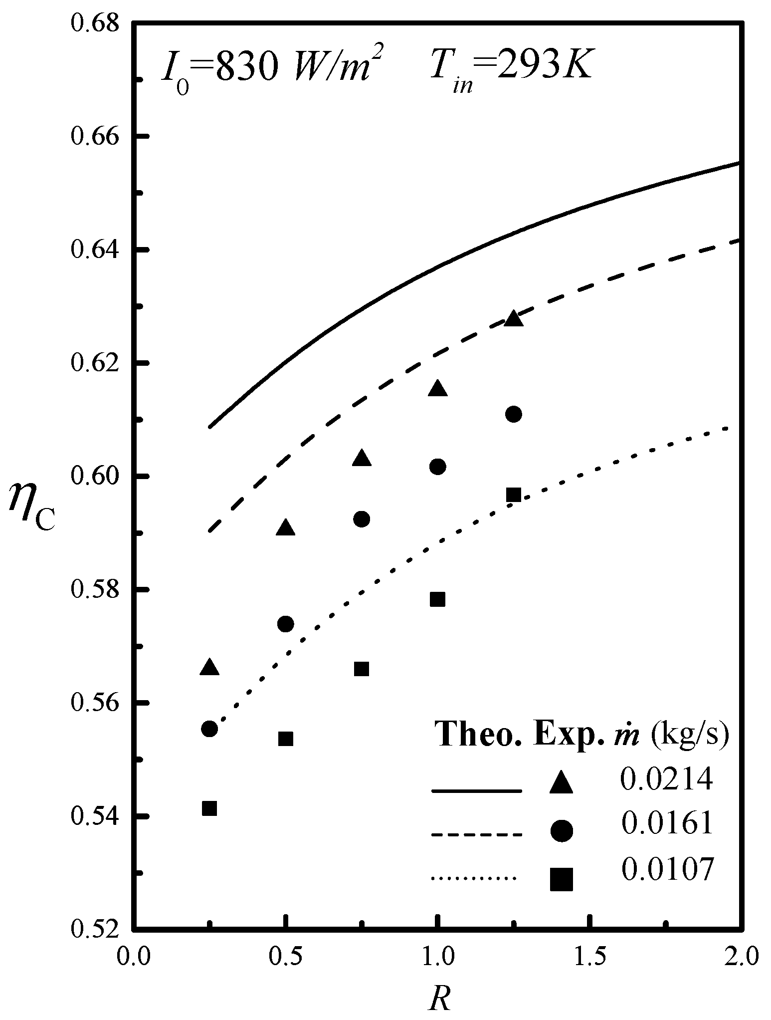
The evaluation procedure for calculating the collector efficiency and the outlet temperature is described while the experimental results of the collector efficiency were then calculated from Equation (24) with measuring the inlet, outlet, ambient and absorber-plate temperatures by thermocouples at the end of each experimental run. With known device geometries (W, L, Hg), physical properties (ks, τg, αp, εg, εp, εR, Cp, μ, ρ) as well as the given operating conditions (I0, Tin, V, ṁ, Ts), an initial guess ηc is first estimated substituting the specified values into Equation (25) with the use of Equation (27) for calculating Ta,L once Tp,m, Ta,m and Tb,m are assumed. The numerical value of the design and operating conditions were given: Ac = 0.09 m2, Hg = 0.05 m, Hc = 0.039 m, L = 0.3 m, W = 0.3 m, αp = 0.96, εg = 0.94, εp = 0.8, εR = 0.94, τg = 0.875, ks= 0.033 W/m K, ṁ = 0.0107, 0.0161 and 0.0214 kg/s, Tin = 20 ± 0.1 °C, Ts = 20 ± 0.1 °C, I0 = 830 ± 20 and 1100 ± 20 W/m2, V = 1.0 m/s. The calculated values Tp,m, Ta,m and Tb,m are thus checked using Equations (20), (21) and (25) by continued iterations, and the final values were obtained until the last values meet the required convergence, and thus, the theoretical prediction of collector efficiency ηc and the outlet temperature Ta,L were obtained accordingly. Comparisons were made and represented in Figure 4 and Figure 5 with the experimental results. The theoretical predictions agree reasonably well with experimental results, as seen from Figure 4 and Figure 5.
4. Collector Efficiency Improvement
The collector efficiency improvement by employing the recycling double-pass cross-corrugated solar air collector is defined by the percentage increase in collector efficiency as compared to that of the downward-type single-pass device under the same total flow rate ṁ and the same working dimensions. The results of collector efficiencies of both theoretical predictions and experimental work for double-pass cross-corrugated devices were presented with incident solar radiation, air mass flowrate and recycle ratio as parameters, as shown in Figure 4 and Figure 5.
Collector efficiencies ηc increase with increasing recycle ratio and air mass flowrate owing to enlarging the flowing air velocity and enhancing convective heat-transfer coefficient. The effects of recycling operations and welding cross-corrugated absorber and bottom plate could augment collector efficiency enhancement significantly with increasing the recycle ratio, incident solar radiations and air mass flow rates. Comparisons of collector efficiencies for both recycling double-pass flat-plate and cross-corrugated double-pass solar air collectors were presented graphically in Figure 6 and Figure 7.
It is also seen that the theoretical collector efficiency of the recycling double-pass cross-corrugated solar air collector is higher than that of recycling operations in double-pass flat-plate device. The collector efficiency improvements, ID, IC and IF, of double-pass flat-plate, cross-corrugated and fins and baffles attached double-pass solar air collector, respectively:
The theoretical predictions of IC for the cross-corrugated double-pass collectors of Tin = 303 °C under various incident solar radiations, air mass flowrate and recycle ratio are presented in Table 1.
The increase of recycle ratio results in the collector efficiency improvement in a more notable extent under the lower air mass flowrate while there is not a significant effect of incident solar radiation on the collector efficiency improvement, as seen from Table 1. The highest collector efficiency improvements were achieved up to 109.4% and 122.4%, respectively, for I0 = 830 and I0 = 1100 W/m2 in operating the lower air mass flow rate, say ṁ = 0.0107 kg/s.
5. Results and Discussion
5.1. Experimental Error Analysis
The accuracy deviation between the experimental results and theoretical predictions was estimated using the following definition as:
where Nexp ηtheo,i and ηexp,i are the number of experimental runs, theoretical predictions and experimental results of collector efficiencies, respectively. The accuracy deviations were shown of two incident solar radiation I0 within 1.39 × 10⁻² ≤ E ≤ 4.41 × 10⁻². The agreement of experimental results with those calculated from theoretical predictions is pretty good.
The further enhancement in collector efficiency Ef by welding a cross-corrugated absorbing plate and a bottom plate was illustrated based on the device of same working dimensions as compared to the flat-plate type:
Equation (50) may be rewritten using Equations (47) and (48) as
The results of Ef were calculated and listed in Table 2. The further collector efficiency enhancement of the device with welding cross-corrugated absorbing plate and bottom plate increases with increasing the air mass flow rate ṁ but with decreasing the solar radiation incident I0 and recycle ratio R, as illustrated in Table 2. Restated, the further enhancements of the collector efficiency as compared to the flat-plate type were achieved considerable increment when the solar air collector was welding cross-corrugated absorbing plate and bottom plate. Applications of welding promoters to the solar air collector with cross-corrugated flow channels were proposed to strengthen the convective heat-transfer coefficient due to creating the higher turbulence intensity, and thus, the larger Nusselt number was achieved. Furthermore, cross-corrugated flow channels associated with external recycle could considerably improve the heat transfer rate as compared to various designs such as single-pass, double-pass flat-plate and double-pass wire mesh packed operations.
5.2. The Power Consumption Increment
The power consumption of the recycling cross-corrugated solar air collector would increase due to the intensive turbulence and the recycle-effect operation. The power consumptions for the flat-plate, cross-corrugated and single-pass solar air collector, respectively, are defined [21] as follows:
in which
The power consumption increments for flat-plate and cross-corrugated devices, IC/IP,C, ID/IP,D and IF/IP,F, respectively, are defined as:
The power consumption increments of both double-pass flat-plate, fins and baffles attached and cross-corrugated devices are based on the power consumption in a single-pass one and also investigated with air mass flowrate and recycle ratio as parameters. Both collector efficiency improvement and power consumption increment, IC/IP,C, ID/IP,D and IF/IP,F, respectively, were taken into account an economic sense for the design and operation of the recycling cross-corrugated double-pass solar air collector, as illustrated in Figure 8. The influences of various recycle ratio and mass flow rate on IC/IP,C, ID/IP,D and IF/IP,F are presented as an illustration in Figure 8 for both recycling flat-plate and cross-corrugated double-pass solar air collectors. The values of IC/IP,C, ID/IP,D and IF/IP,F reach an optimal recycle ratio under for all air mass flowrates, say R = 0.5, and move away from R = 0.5 due to the larger power consumption increment for R > 0.5 and the smaller collector efficiency improvement for R < 0.5. The increase of the higher values of IC/IP,C, ID/IP,D and IF/IP,F indicates the collector efficiency improvement is more effective at the expenses of energy consumption. Figure 8 shows that the cross-corrugated double-pass solar air collector is the more economical configuration owing to the higher useful energy gain and a relative less power consumption increment.
6. Conclusions
Theoretical and experimental studies of collector performance of recycling cross-corrugated double-pass solar air collectors were investigated with consideration of the hydraulic dissipated energy. The turbulence promotor by welding a cross-corrugated absorbing plate and a bottom plate in solar air collectors with external recycle is the aim to achieve the augmented turbulence intensity and enlarge the heat transfer area as well, and thus, the collector efficiency is enhanced. The present work is actually the extension of our previous work [26] except welding cross-corrugated plates instead of fins and baffles. A comparison of the economic consideration, say the ratio of the efficiency improvement and power consumption increment IC/IP,C, ID/IP,D and IF/IP,F, has been conducted under the same design and operating parameters. The conclusion of the present findings are as follows: (1) application of the recycling operation to double-pass cross-corrugated solar air collectors is technically and economically feasible and could accomplish a higher thermal performance as compared to both flat-plate and fins and baffles attached solar air collectors; (2) thermal performance improvements increase with increasing the recycle ratio but with decreasing the air mass flow rate; (3) evaluations of the economic sense come out with the optimal operating condition at R = 0.5 for compensating a relative lower hydraulic dissipated energy increment; (4) The advantage of the present design is evident and provides an important contribution to improved solar air collectors instead of using the flat-plate device and the device with attaching fins and baffles.
Acknowledgments
The authors wish to thank the National Science Council of the Republic of China for its financial support.
Author Contributions
This paper is a result of the full collaboration of all the authors. However, the concept for this research was conceived by Chii-Dong Ho, Hsuan Chang and Chien-Chang Huang elaborated the manuscript preparation, and Ching-Fang Hsiao performed the experiments and contributed to mathematical derivations.
Conflicts of Interest
The authors declare no conflict of interest.
Nomenclature
| Ac | surface area of the collector = LW (m2) |
| Bi | coefficients defined in Equations (A1)–(A6), i = 1, 2, …, 6 |
| Ci | coefficients defined in Equations (A16) and (A17), i = 1, 2 |
| Cp | specific heat of air at constant pressure (J/(kg K)) |
| De0 | equivalent hydraulic diameter of the single-pass device (m) |
| Dea | equivalent hydraulic diameter of the lower subchannel of double-pass device (m) |
| Deb | equivalent hydraulic diameter of the upper subchannel of double-pass device (m) |
| E | deviation of the experimental measurements from theoretical predictions, defined in Equation (51) |
| Ef | the further enhancement in collector efficiency, defined in Equation (51) |
| fF | Fanning friction factor |
| Fi | coefficients defined in Equations (A18)–(A20), i = 1, 2, 3 |
| Gi | coefficients defined in Equations (A7)–(A13), i = 1, 2, …, 7 |
| Hc | the average gap thickness the inner cover and the absorbing plate (m) |
| Hg | the average gap between the absorbing plate and the bottom plate (m) |
| h0 | convection coefficient in the single-pass device (W/m2·K) |
| ha | convection coefficient between the bottom and lower subchannel (W/m2·K) |
| h’a | convection coefficient between the absorber plate and lower subchannel (W/m2·K) |
| hb | convection coefficient between the absorber plate and upper subchannel (W/m2·K) |
| h’b | convection coefficient between the inner cover and upper subchannel (W/m2·K) |
| hc1-c2 | convective coefficient between two glass covers (W/m2·K) |
| hr,c1-c2 | radiation coefficient between two glass covers, (W/m2·K) |
| hr,c2-s | radiation coefficient from the outer cover to the ambient (W/m2·K) |
| hr,p-c1 | radiation coefficient between the inner cover and absorber plate (W/m2·K) |
| hr,p-R | radiation coefficient between absorber plate and bottom plate (W/m2·K) |
| hw | convective coefficient for air flowing over the outer cover (W/m2·K) |
| I0 | Incident solar radiation (W/m2) |
| Ii | coefficients defined in Equations (A21) and (A22), i = 1, 2 |
| IP,C | percentage of power consumption increment, defined in Equation (58) |
| IP,D | percentage of power consumption increment, defined in Equation (59) |
| IP,F | percentage of power consumption increment, defined in Equation (60) |
| IC | percentage of collector efficiency improvement in cross-corrugated type, defined in Equation (48) |
| ID | percentage of collector efficiency improvement in flat-plate type, defined in Equation (47) |
| IF | percentage of collector efficiency improvement in fins and baffles attached, defined in Equation (49) |
| k | thermal conductivity of the stainless steel plate (W/m·K) |
| ks | thermal conductivity of insulator (W/m·K) |
| L | channel length (m) |
| ls | thickness of insulator (m) |
| ℓ𝑤𝑓,a | the lower subchannel friction loss of double-pass device (J/kg) |
| ℓ𝑤𝑓,b | the upper subchannel friction loss of double-pass device (J/kg) |
| ℓ𝑤𝑓,s | friction loss of downward-type single-pass device (J/kg) |
| M1 | parameter defined in Equation (16) (W/ m2·K) |
| M2 | parameter defined in Equation (16) (W/ m2·K) |
| ṁ | air mass flowrate (kg/s) |
| Nexp | the number of the experimental measurements |
| Nu0 | Nusselt number in the flat-plate collector |
| Nua | Nusselt number in the lower subchannel |
| Nub | Nusselt number in the upper subchannel |
| PC,S | power consumption for the cross-corrugated solar air collector (W) |
| PC,C | power consumption for the single-pass solar air collector (W) |
| PC,D | power consumption for the double-pass flat-plate solar air collector (W) |
| PC,F | power consumption for double-pass fins and baffles attached solar air collector (W) |
| Qu | useful energy gain by flowing air (W) |
| R | recycle ratio |
| Ra | Reynolds Number defined in Equation (34) |
| Re0 | Reynolds Number defined in Equation (29a) |
| Rea | Reynolds Number defined in Equation (29b) |
| Reb | Reynolds Number defined in Equation (29c) |
| Ta(z) | axial fluid temperature distribution in the lower subchannel (K) |
| Tb(z) | axial fluid temperature distribution in the upper subchannel (K) |
| Ta(ξ) | dimensionless axial temperature distribution in the lower subchannel (K) |
| Tb(ξ) | dimensionless axial temperature distribution in the upper subchannel (K) |
| the mixing temperature of the lower subchannel a at x = 0 (K) | |
| Ta,L | the outlet temperature of the lower subchannel (K) |
| Tb,0 | the temperature of the upper subchannel b at x = 0 (K) |
| Tb,L | the temperature of the upper subchannel at x = L (K) |
| Ta,m | average temperature of the lower subchannel (K) |
| Tb,m | average temperature of the upper subchannel (K) |
| Tc1 | temperature of the inner glass cover (K) |
| Tc2 | temperature of the outer glass cover (K) |
| Tc1,m | average temperature of the inner glass cover (K) |
| Tc2,m | average temperature of the outer glass cover (K) |
| Tin | the inlet temperature of the lower subchannel (K) |
| TP | temperature of corrugated absorbing plate (K) |
| Tp,m | average temperature of corrugated absorbing plate (K) |
| TR | temperature of bottom plate (K) |
| Ts | ambient temperature (K) |
| UB | loss coefficient from the bottom plate to the ambient (W/ m2·K) |
| UB-s | loss coefficient from the surfaces of edges and bottom to the ambient (W/ m2·K) |
| Uc1-s | loss coefficient from the inner cover to the ambient (W/ m2·K) |
| UL | overall loss coefficient (W/ m2·K) |
| UT | loss coefficient from the top to the ambient (W/ m2·K) |
| V | wind velocity (m/s) |
| the average velocity of the single-pass device (m/s) | |
| the average velocity of the lower subchannel (m/s) | |
| the average velocity of the upper subchannel (m/s) | |
| Yi | coefficient defined in Equations (A30) and (A31), i = 1, 2 |
| W | collector width (m) |
| z | axial coordinate along the flow direction (m) |
| Greek Letters | |
| αp | absorptivity of the absorbing plate |
| β | thermal expansion coefficient (1/K) |
| ηc | collector efficiency of cross-corrugated solar air heater |
| ηD | collector efficiency of the double-pass flat-plate |
| ηS | collector efficiency of the downward-type single-pass device |
| ηexp,i | experimental data of collector efficiency |
| ηtheo,i | theoretical prediction of collector efficiency |
| τg | transmittance of glass cover |
| εg | emissivity of glass cover |
| εp | emissivity of absorbing plate |
| ρ | air density (kg/m3) |
| μ | air viscosity (kg/ m·s) |
| σ | Stefan-Boltzmann constant (=5.682 × 10⁻⁸) (W/m2·K4) |
| ξ | dimensionless channel position |
Appendix A
Detailed derivations of the simultaneous system equations
The two distinct roots of two simultaneous linear ordinary differential equations, Equations (14) and (15), are as follows:
Substitutions of the boundary conditions Equations (18) and (19) into Equations (14) and (15) give the temperature distributions Equations (20) and (21) with the undetermined coefficients C1 and C2 as follows:
in which:
References
- Chen, X.; Yang, H.; Lu, L.; Wang, J.; Liu, W. Experimental studies on a ground coupled heat pump with solar thermal collectors for space heating. Energy 2011, 36, 5292–5300. [Google Scholar]
- Design, S.S. Experimental investigation and analysis of a solar drying system. Energy Convers. Manag. 2013, 8, 27–34. [Google Scholar]
- El-Sebaii, A.A.; Shalaby, S.M. Experimental investigation of an indirect-mode forced convection solar dryer for drying thymus and mint. Energy Convers. Manag. 2013, 74, 109–116. [Google Scholar] [CrossRef]
- Bari, E.; Noel, J.Y.; Comini, G.; Cortella, G. Air-cooled condensing systems for home and industrial appliances. Appl. Therm. Eng. 2005, 25, 1446–1458. [Google Scholar] [CrossRef]
- Chen, Z.; Gu, M.; Peng, D.; Peng, C.; Wu, Z. A numerical study on heat transfer of high efficient solar flat-plate collectors with energy storage. Int. J. Green Energy 2010, 7, 326–336. [Google Scholar] [CrossRef]
- Sharma, K.S.; Kalamkar, V.R. Experimental and numerical investigation of forced convection heat transfer in solar air heater with thin ribs. Sol. Energy 2017, 147, 277–291. [Google Scholar] [CrossRef]
- Tamna, S.; Skullong, S.; Thianpong, C.; Promvonge, P. Heat transfer behaviors in a solar air heater channel with multiple V-baffle vortex generators. Sol. Energy 2014, 10, 720–735. [Google Scholar] [CrossRef]
- Hosseini, S.S.; Ramiar, A.; Ranjbar, A.A. Numerical investigation of natural convection solar air heater with different fins shape. Renew. Energy 2018, 117, 488–500. [Google Scholar] [CrossRef]
- Gilani, S.E.; Al-Kayiem, H.H.; Woldemicheal, D.E.; Gilani, S.I. Performance enhancement of free convective solar air heater by pin protrusions on the absorber. Sol. Energy 2017, 151, 173–185. [Google Scholar] [CrossRef]
- Prasad, B.N.; Kumar, A.; Singh, K.D.P. Optimization of thermos hydraulic performance in three sides artificially roughened solar air heaters. Sol. Energy 2015, 111, 313–319. [Google Scholar] [CrossRef]
- Languri, E.M.; Taherian, H.; Hooman, K.; Reisel, J. Enhanced double-pass solar air heater with and without porous medium. Int. J. Green Energy 2011, 8, 643–654. [Google Scholar] [CrossRef]
- Nowzari, R.; Aldabbagh, L.B.Y.; Egelioglu, F. Single and double pass solar air heaters with partially perforated cover and packed mesh. Energy 2014, 73, 694–702. [Google Scholar] [CrossRef]
- Ho, C.D.; Lin, C.S.; Chuang, Y.C.; Chao, C.C. Performance of wire mesh packed double-pass solar air heaters with external recycle. Renew. Energy 2013, 57, 479–489. [Google Scholar] [CrossRef]
- Karim, M.A.; Perez, E.; Amin, Z.M. Mathematical modelling of counter flow v-grove solar air collector. Renew. Energy 2014, 67, 192–201. [Google Scholar] [CrossRef]
- Mohammadi, K.; Sabzpooshani, M. Appraising the performance of a baffled solar air heater with external recycle. Energy Convers. Manag. 2014, 88, 239–250. [Google Scholar] [CrossRef]
- Gao, W.F.; Lin, W.X.; Liu, T.; Xia, C.F. Analytical and experimental studies on the thermal performance of cross-corrugated and flat-plate solar air heaters. Appl. Energy 2007, 84, 425–441. [Google Scholar] [CrossRef]
- Kabeel, A.E.; Khalil, A.; Shalaby, S.M.; Zayed, M.E. Experimental investigation of thermal performance of flat and v-corrugated plate solar air heaters with and without PCM as thermal energy storage. Energy Convers. Manag. 2016, 113, 264–272. [Google Scholar] [CrossRef]
- Hottel, H.C.; Woetz, B.B. The performance of flat-plate solar-heat collectors. Trans. ASME 1942, 64, 91–104. [Google Scholar]
- Klein, S.A. Calculation of flat-plate loss coefficients. Sol. Energy 1979, 17, 79–80. [Google Scholar] [CrossRef]
- Piao, Y.; Hauptmann, E.G.; Iqbal, M. Forced convective heat transfer in cross-corrugated solar air heaters. J. Sol. Energy Eng. 1994, 116, 212–214. [Google Scholar] [CrossRef]
- Zhang, L.Z. Numerical study of periodically fully developed flow and heat transfer in cross-corrugated triangular channels in transitional flow regime. Numer. Heat Transf. Part A 2005, 48, 387–405. [Google Scholar] [CrossRef]
- Lin, W.X.; Gao, W.F.; Liu, T. A parametric study of the thermal performance of cross-corrugated solar air collectors. Appl. Therm. Eng. 2006, 26, 1043–1053. [Google Scholar] [CrossRef]
- Kays, W.M. Convective Heat and Mass Transfer, 3rd ed.; McGraw-Hill: New York, NY, USA, 1993. [Google Scholar]
- McAdams, W.H. Heat Transmission, 3rd ed.; McGraw-Hill: New York, NY, USA, 1954. [Google Scholar]
- Heaton, H.S.; Reynolds, W.C.; Kays, W.M. Heat transfer in annular passages. simultaneous development of velocity and temperature fields in laminar flow. Int. J. Heat Mass Transf. 1964, 7, 763–781. [Google Scholar] [CrossRef]
- Ho, C.D.; Chang, H.; Wang, R.C.; Lin, C.S. Performance improvement of a double-pass solar air heater with fins and baffles under recycling operation. Appl. Energy 2012, 100, 155–163. [Google Scholar] [CrossRef]
Figure 1.
A schematic drawing of recycling double-pass cross-corrugated solar air collector.

Figure 2.
The energy balance made within a finite fluid element.
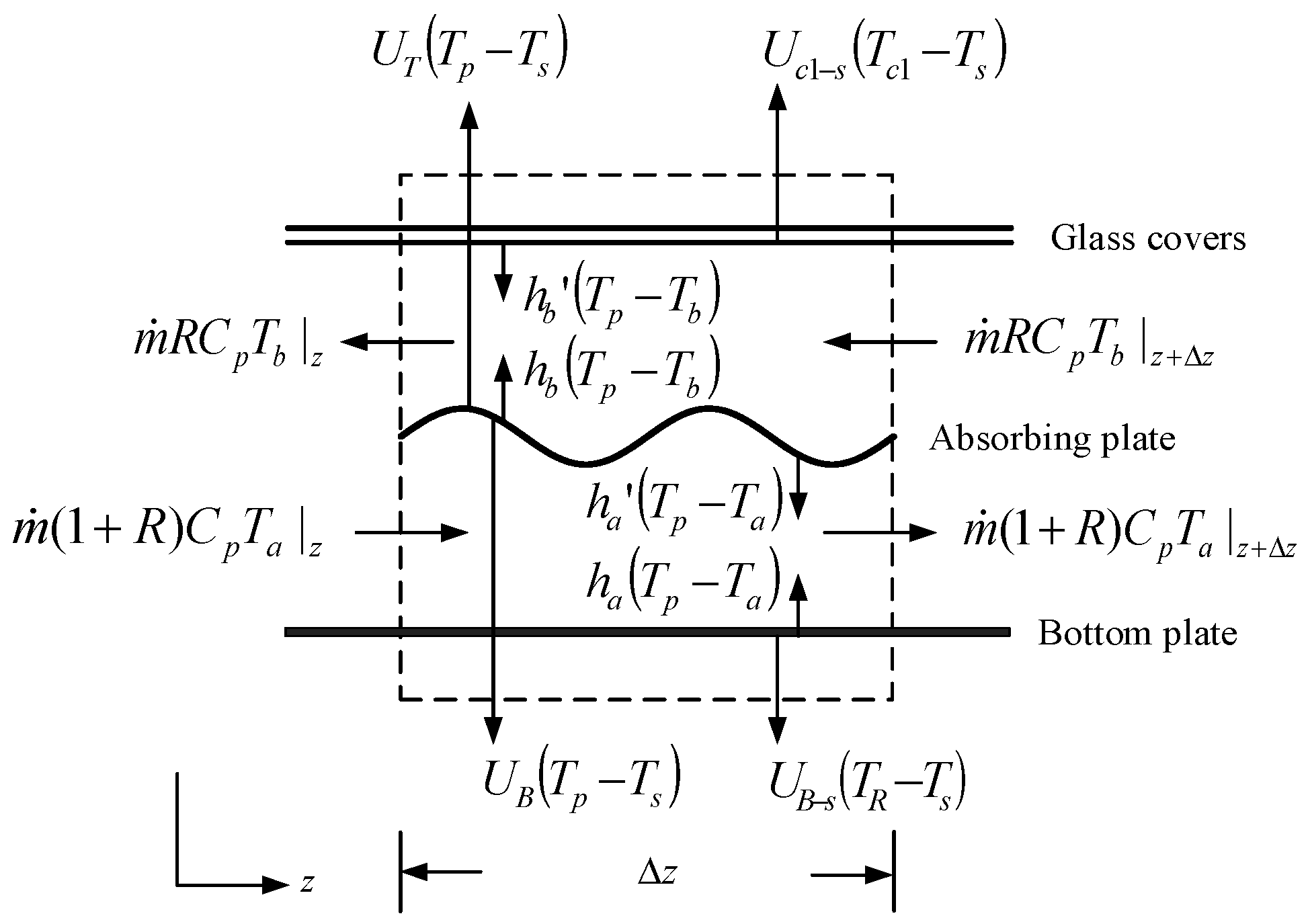
Figure 3.
Experimental setup of recycling cross-corrugated double-pass solar air collector.

Figure 4.
Effect of the recycle ratio on collector efficiency of the recycling cross-corrugated solar air collector (I0 = 830 W/m2).
Figure 4.
Effect of the recycle ratio on collector efficiency of the recycling cross-corrugated solar air collector (I0 = 830 W/m2).

Figure 5.
Effect of the recycle ratio on collector efficiency of the recycling cross-corrugated solar air collector (I0 = 1100 W/m2).
Figure 5.
Effect of the recycle ratio on collector efficiency of the recycling cross-corrugated solar air collector (I0 = 1100 W/m2).

Figure 6.
Comparisons of collector efficiencies for both recycling flat-plate and cross-corrugated solar air collectors (I0 = 830 W/m2).
Figure 6.
Comparisons of collector efficiencies for both recycling flat-plate and cross-corrugated solar air collectors (I0 = 830 W/m2).

Figure 7.
Comparisons of collector efficiencies for both recycling flat-plate and cross-corrugated solar air collectors (I0 = 1100 W/m2).
Figure 7.
Comparisons of collector efficiencies for both recycling flat-plate and cross-corrugated solar air collectors (I0 = 1100 W/m2).

Figure 8.
The values of IC/IP,C, ID/IP,D and IF/IP,F vs. R and ṁ as a parameter.


Table 1.
Theoretical predictions of collector efficiency ηc and improvement IC for I0 = 830 W/m2 and I0 = 1100 W/m2.
Table 1.
Theoretical predictions of collector efficiency ηc and improvement IC for I0 = 830 W/m2 and I0 = 1100 W/m2.
| ṁ | Recycle Ratio | I0 = 830 (W/m2) | I0 = 1100 (W/m2) | ||
|---|---|---|---|---|---|
| (kg/s) | R | ηc (%) | IC (%) | ηc (%) | IC (%) |
| 0.0107 | 0.25 | 0.550 | 91.62 | 0.281 | 103.5 |
| 0.5 | 0.563 | 96.32 | 0.586 | 108.5 | |
| 0.75 | 0.574 | 99.92 | 0.597 | 112.4 | |
| 1 | 0.582 | 102.7 | 0.605 | 115.3 | |
| 1.25 | 0.588 | 105.0 | 0.612 | 117.7 | |
| 1.5 | 0.593 | 106.8 | 0.617 | 119.6 | |
| 1.75 | 0.598 | 108.2 | 0.621 | 121.2 | |
| 2 | 0.601 | 109.4 | 0.625 | 122.4 | |
| 0.0214 | 0.25 | 0.605 | 51.97 | 0.629 | 60.47 |
| 0.5 | 0.616 | 54.78 | 0.641 | 63.43 | |
| 0.75 | 0.625 | 56.93 | 0.650 | 65.70 | |
| 1 | 0.631 | 58.63 | 0.657 | 67.50 | |
| 1.25 | 0.637 | 60.00 | 0.662 | 68.95 | |
| 1.5 | 0.641 | 61.12 | 0.667 | 70.13 | |
| 1.75 | 0.645 | 62.05 | 0.671 | 71.12 | |
| 2 | 0.648 | 62.83 | 0.674 | 71.93 | |
Table 2.
The further enhancement in collector efficiency with cross-corrugated absorber, (a) I0 = 830 W/m2; (b) I0 = 1100 W/m2.
Table 2.
The further enhancement in collector efficiency with cross-corrugated absorber, (a) I0 = 830 W/m2; (b) I0 = 1100 W/m2.
| I0 | R | Ef (%) | |
|---|---|---|---|
| ṁ = 0.017 (kg/s) | ṁ = 0.0214 (kg/s) | ||
| (a) | 0.25 | 59.14 | 67.38 |
| 0.5 | 50.93 | 58.89 | |
| 0.75 | 45.85 | 53.72 | |
| 1.0 | 41.97 | 49.69 | |
| 1.25 | 38.88 | 46.49 | |
| 1.5 | 36.24 | 43.77 | |
| 1.75 | 33.93 | 41.46 | |
| 2.0 | 31.93 | 39.36 | |
| (b) | 0.25 | 34.79 | 39.86 |
| 0.5 | 29.70 | 34.63 | |
| 0.75 | 26.55 | 31.42 | |
| 1.0 | 24.19 | 29.02 | |
| 1.25 | 22.31 | 27.17 | |
| 1.5 | 20.73 | 25.52 | |
| 1.75 | 19.41 | 24.17 | |
| 2.0 | 18.26 | 22.98 | |
© 2018 by the authors. Licensee MDPI, Basel, Switzerland. This article is an open access article distributed under the terms and conditions of the Creative Commons Attribution (CC BY) license (http://creativecommons.org/licenses/by/4.0/).
Share and Cite
MDPI and ACS Style
Ho, C.-D.; Chang, H.; Hsiao, C.-F.; Huang, C.-C. Device Performance Improvement of Recycling Double-Pass Cross-Corrugated Solar Air Collectors. Energies 2018, 11, 338. https://doi.org/10.3390/en11020338
AMA Style
Ho C-D, Chang H, Hsiao C-F, Huang C-C. Device Performance Improvement of Recycling Double-Pass Cross-Corrugated Solar Air Collectors. Energies. 2018; 11(2):338. https://doi.org/10.3390/en11020338
Chicago/Turabian StyleHo, Chii-Dong, Hsuan Chang, Ching-Fang Hsiao, and Chien-Chang Huang. 2018. "Device Performance Improvement of Recycling Double-Pass Cross-Corrugated Solar Air Collectors" Energies 11, no. 2: 338. https://doi.org/10.3390/en11020338
Note that from the first issue of 2016, this journal uses article numbers instead of page numbers. See further details here.