On Reducing the Shaft Torque Ripple of Small-to-Medium-Scale Wind Energy Conversion Systems Using Multi-Pulse Autotransformer Rectifier


1
College of Automation Engineering, Nanjing University of Aeronautics and Astronautics, Nanjing 211106, China
2
College of Automation, Chongqing University, Chongqing 400044, China
*
Author to whom correspondence should be addressed.
Energies 2018, 11(2), 379; https://doi.org/10.3390/en11020379
Submission received: 17 January 2018
/
Revised: 1 February 2018
/
Accepted: 2 February 2018
/
Published: 6 February 2018
(This article belongs to the Section A: Sustainable Energy)
Abstract
:In a small-to-medium-scale wind energy conversion system (WECS), diode rectifiers rather than pulse-width modulated (PWM) rectifiers are widely adopted due to the features of high reliability and low cost. However, large current harmonics are induced in the generator phase current by commutations of diode rectifier, eventually causing large torque ripple on the drive-train of the WECS and making it more likely to be fatigue breakdown. In this paper, a 12-pulse autotransformer rectifier unit (ATRU) with reduced volume and weight is proposed for WECS application. By analyzing the characteristics of the input current and output voltage of the ATRU within the entire operation range of WECS, the method to properly design its parameters is proposed. A 1.2 kW direct-drive WECS demonstration platform using ATRU is built in the lab. A modified sensorless overall power control strategy is adopted to control the WECS. Experimental tests are carried out and the results not only validate the feasibility of implementing ATRU in WECS applications, but also prove its high torque ripple reduction ability.
1. Introduction
Small-to-medium-scale (1–100 kW) wind energy conversion system (WECS) is developing very rapidly recently, not only because it is one of the major ways to meet the electricity needs of users in remote areas, but also it is one of the key micro generators (MGs) in microgrids. Most recently, wind market reports of the British Wind Energy Association and the U.S. Department of Energy (DOE) show that wind turbines with unity capacity below 100 kW contribute 248 MW and 906 MW of generated power in the UK and U.S. respectively. The average annual growth rate is predicted at more than 5% worldwide [1,2].
In small-to-medium-scale WECS market, the permanent magnet synchronous generator (PMSG)-based direct-drive fixed-pitch structure is preferred due to its high efficiency and high reliability [3,4]. Modern WECS usually operates in a variable-speed way to optimize generated power, which results in a variable frequency output power. Therefore, in industry, a back-to-back alternating frequency (AC)–AC converter is needed between the generator output and the utility grid [5,6,7]. For the generator-side rectifier, fully pulse-width-modulated (PWM) full-bridge rectifiers are widely adopted in large-scale WECS owing to its strong ability of correcting power factor and suppressing total harmonic distortions (THDs) of generator voltage and current. However, it is not preferred in small-to-medium-scale wind turbines, especially small-scale WECSs, considering the increased cost and compromised reliability, which is mainly resultant from the use of large numbers of fully controlled power switches, and the possibility of shoot-through for such topologies [8,9,10]. Instead, diode rectifiers, together with boost converters, are more highly preferred for such WECS [11,12].
However, when a full-bridge diode rectifier is used in the WECS, a large torque ripple will be induced by a large current THD, caused by the commutation overlap effect of the diode rectifier [13,14]. For example, Figure 1 shows some tested results of a 1.2 kW WECS demonstration platform established in [13] at wind speed 10 m/s. In this figure, the structure of the WECS is depicted in Figure 1a. The power coefficient of the turbine blade is given in Figure 1b. The control algorithm adopted for the WECS includes the maximum power point tracking (MPPT) control in low wind speed range and the constant speed and constant power control in the high wind speed range. The detailed operational principle can be referred to [13]. From the tested results shown in Figure 1c, it can be noticed that the generator phase current is highly distorted and contains rich low-order harmonics, which would eventually induce large torque ripple on the drive train, making it more likely to be fatigue breakdown.
To reduce harmonics, one simple and feasible solution is to employ a multi-pulse rectifier to replace the diode rectifier. A multi-pulse rectifier is a rectifier composed of diode rectifiers connected in parallel through a phase-shifting transformer to provide inherent high power factor and low THD. So far, multi-pulse rectifier technology is highly used in aircraft power system, the fundamental frequency of which is 360–800 Hz and very good for reducing the volume and weight of transformer [15,16,17]. However, in WECS application, considering the quite low rotor speed, i.e., low fundamental frequency, the volume and weight of the transformer might be increased dramatically if the conventional multi-pulse technology had still been adopted. Taking the WECS in [13] as an example, if the most commonly used 12-pulse rectifier in industry is adopted, which requires two six-pulse converters connected through Y-Δ and Y-Y isolation transformers, the volume and weight of the transformer should be very large considering the low electric frequency (maximum 33.3 Hz) and high magnetic rating of the transformer (1.03 times of the maximum output power [18]). This inevitably would increase the system’s cost. Currently, some exciting research achievements with ATRU technology with reduced magnetic rating of the transformer can be evidenced [19,20]. In [19], a modified 12-pulse auto-transformer rectifier unit (ATRU) is proposed. The magnetic rating of the transformer is reported to be 56% of the output power. In [20], star, polygon and delta-polygon auto-connected 12-pulse rectifiers are proposed, with the magnetic ratings being reduced to 33.5%, 22.9% and 16.4% of the output power respectively. Even though there is a huge reduction on the delta-polygon auto-connected 12-pulse rectifier, the THD of the mains current may be higher than other topologies. This eventually increases the shaft torque ripple and further shortens the service life of the WECS. To reduce its current THD, harmonic current injection methods may be used [21]. However, the requirement of extra hardware and controllers will increase the system complexity and cost for small-to-medium scale WECS. In addition, there are no research works that considered the design and implementation of multi-pulse rectifiers in the application of WECS in a systematic way so far. This means that either the performances of a wind turbine were not considered in the design process of the rectifier, or that the experimental tests on the performances of ATRU in WECS application were not shown in the implementation. Therefore, further investigations are still needed.
In this paper, a 12-pulse ATRU was designed and implemented for WECS application [22,23]. The ATRU not only had inherent high power factor and low harmonic distortion features, which indicates low torque ripple, but was also of highly robust, efficient and low cost. Most importantly, it is available to reduce the volume and weight of the ATRU, owing to the reduction on the magnetic rating of the bulky autotransformer. However, considering the rather complicated operational states of wind turbines, the complexity in the design of ATRU, especially on the autotransformer, will undoubtedly add difficulty to its implementation. To address this issue, a systematic study on the system design and implementation is conducted.
The rest of the paper is organized as follows: The structure of a small-scale WECS with ATRU is briefed in Section 2. The characteristics and the design details of ATRU are presented in the same section, combining with the performances of WECS within the entire wind speed range. In Section 3, a modified overall power control strategy is adopted to handle the issue related to current harmonics reduction. Then, Section 4 illustrates the experimental tests and results of the system with ATRU based on a 1.2 kW laboratory prototype. The feasibility of using ATRU in WECS application is verified by the obtained experimental results. Finally, the paper is concluded in Section 5.
2. Design of the 12-Pulse ATRU in WECS
2.1. Structure of the Proposed ATRU
The configuration of the studied 12-pulse ATRU is given in Figure 2. The core configuration of the phase shifting autotransformer is shown in Figure 2a wherein the dotted terminals of the windings are clearly marked. The winding representation on a three-limb core is depicted in Figure 2b. It can be observed that there are three windings on each limb. They are mounted in a way to achieve proper phase shifting. Taking the middle limb as an example, long winding b′c″ and the short windings a′a and aa″ are mounted in the same direction, which results in the same direction for voltage phasors Vb′c″, Va′a and Vaa″. Considering the 120-degree phase shifting among the input three voltage phasors Va, Vb and Vc, one can conclude that the shape formed by VbVcVc″Vb′ is an isosceles trapezoid, which also indicates that Vcb and Vc″b′ are parallel to each other and vertical to Va. As a result, Va′a and Vaa″ are also perpendicular to Va, considering that it is in the same direction as Vc″b′. Hence, phase shifting voltages Va′ and Va″ are generated on the secondary windings. The complete voltage phasor diagram is shown in Figure 2c. Note that the shifting angle can be adjusted by choosing different turns-ratio between the long and short windings.
Suppose that the required phase shifting is already achieved using turns-ratio adjustment and assume that the rms values of the voltages across the primary and secondary windings are Vin and Vs respectively. From Figure 2c, we have,
where n takes a, b, c. From this equation, it can be determined that the magnitude of secondary voltages is 103.53% of the original primary voltage.
Furthermore, assume that the turns of the long and short windings on each limb are Np and Ns, and that their rms voltages are VNp and VNs respectively. Based on the voltage phasor diagram, we can deduce:
The turns-ratio between long and short windings is:
Hence, Equation (4) shows the guideline to design the turns-ratio of the autotransformer to achieve the required voltage phasor diagram shown in Figure 2c.
2.2. Characteristics of the Output Voltage
As shown in Figure 2a, the output voltage sets of the secondary windings are connected to two diode bridges. The output voltage of the ATRU is then resulted from connecting the output voltages of the two diode bridges in parallel. Balancing reactors are added at the output terminals of each diode bridges to widen the conduction angle of the diodes and to decrease the currents flowing through them. With the balancing reactors, the output voltage of the ATRU can be deduced as:
where vd1, vd2, vpn, vqn, vxn and vyn are the voltages defined on the balancing reactors, as shown in Figure 2a. Keeping in mind the operational principle of the diode rectifiers and considering Figure 2b, we can draw the output voltage of each diode bridge, i.e., vd1, vd2, and the output voltage of ATRU, i.e., Vlink in Figure 3, from which average value of the output voltage can be deduced:
In order to optimize the turbine power, the rotor speed has to be properly controlled to force the system follow the optimum power line [13]. For small-to-medium-scale WECS, sensorless control is always preferred for reducing the overall cost. A commonly adopted way to achieve this is to implement the so called phase-locked-loop (PLL) technique to estimate the rotor speed through electrical variables [24,25,26]. It is effective and can also be adopted here. However, in this paper, an even simpler method was used, which is described and discussed as follows.
It is known that the electromotive force E of a permanent magnet synchronous generator (PMSG) is proportional to its rotational speed ω, i.e.,
where Φ is the flux, Ke = 0.71Nstkwp is potential constant, in which Nst is the stator winding turns and kw is fundamental winding factor, and p represents the pole pairs.
The output voltage of the generator, which is also the voltage across the primary winding of the ATRU, is:
where I is the generator phase current, RsG and LsG are the resistance and inductance of stator windings, p is the pole pairs.
From Equations (6)–(8), we have:
Hence, one can use the direct current (DC)-link voltage Vlink to estimate the rotor speed of the PMSG according to Equation (9). However, the relationship shown in Equation (9) is nonlinear because of the existence of changing winding resistance RsG and inductance LsG, which eventually makes the implementation of the sensorless control very complicated. To overcome this, a straight-line approximation between Vlink and ω, which coincides with the true relationship shown in Equation (9) at higher speeds more precisely, is made. In such a way, although the chosen straight-line approximation will not provide optimum power capture at low wind speeds, the relatively low power of the system at low wind speeds makes the approximation acceptable. More importantly, controlling the WECS is significantly simplified.
After using the straight-line approximation, we have:
where kω is a constant.
2.3. THD Analysis of the Input Current
While analyzing the characteristics of the input current, the output current of the ATRU is treated as continuous considering the existence of a large boost inductor L. The magnetic balance equations of the autotransformer shown in Figure 2b are:
where (iA, iB, iC), (ia1, ib1, ic1) and (ia2, ib2, ic2) are the currents in long and short windings respectively.
Applying Kirchhoff’s current law (KCL) at the nodes a, a′, a″, b, b′, b″, c, c′, c″ yields:
Considering Equations (11) and (12) and Figure 2, one can obtain the current waveforms of each winding as shown in Figure 4.
Taking phase A as an example, its input current is given as:
Its Fourier expansion is:
Hence, it is found that the harmonics distribution of the input current of each phase is (12k ± 1, where k = 1, 2, 3…) with the lowest harmonics order being 11th and the fundamental current component being:
where Iaf is the rms value of the fundamental current.
Therefore, the total harmonic distortion (THD) of the input current of the 12-pulse ATRU can be calculated as:
It should be pointed out that in real application, the tested THD would be much lower than the theoretical value due to the existence of line impedance, leakage inductance of the autotransformer (Ls) and the stator winding inductance.
Moreover, the rms values of the currents of the long and short windings can also be deduced as:
Combining Equations (2)–(6) and (16) and (17), the magnetic rating of the autotransformer Patr can be deduced as:
Remark 1.
It is known from Equation (19) that the needed magnetic rating of the transformer used in the studied ATRU is only 18.2% of the output power P0. Comparing with that required by the most commonly used 12-pulse rectifier, which is 103% of the output power [18], this is a huge reduction. On the other hand, comparing with the delta-polygon ATRU proposed in [20], which is more superior in reducing the system volume and weight as the magnetic rating is only 16.4% of the conventional ATRU, the proposed ATRU is better at reducing the shaft torque ripple because its current THD is lesser. As a result, a better trade-off between the system volume and weight and the shaft torque ripple is obtained using the proposed ATRU.
2.4. Designing of the Autotransformer in WECS Application
Considering the variable-speed operation of WECS, the output power of the generator is of variable frequency. Thus, the autotransformer has to be well designed to prevent its magnetic core from saturation in the system’s entire operation range.
Typically, there are three operational modes for a variable speed WECS, namely maximum power point tracking (MPPT) operation mode at low wind speed region, constant speed (CS) operation mode when wind speed varies between rated rotor speed corresponding wind speed vΩN and rated wind speed vN, and constant power (CP) operation mode when wind speed is above rated value [27].
According to aerodynamics, the mechanical power captured by the wind turbine can be determined as [27]:
where Pr is the mechanical power, ρ is the air density, R is the radius of the swept area, v stands for the wind speed, Cp(λ, β) is the power coefficient, with β being the pitch angle and λ being the tip-speed-ratio, which is determined by:
The WECS can be categorized into two types determined by the changeability of the pitch angle β, namely fixed-pitch WECS and variable-pitch WECS. The control methods of these two types of WECSs are the same in MPPT and CS regions, while they are different from each other in the CP region. More specifically, pitch angle regulation is always applied to the latter because it is adjustable, while electrical control is applied to the former, since there is no such a control degree of freedom. As a result, there are some differences in designing the autotransformer, which are elaborated below.
In the MPPT operation region, the rotor speed is adjusted accordingly to keep the system operating at the optimum tip-speed-ratio λopt. The optimum power is expressed as [13]:
where vcut-in is the cut-in wind speed, and kopt is determined by:
When wind speed increases up to vΩN, where the rotor speed reaches rated value ΩN, WECS turns into operation at CS mode to get rid of over-speeding problem. That is, the rotor speed is maintained constant at ΩN. In this mode, the power generated can be deduced from Equation (20) as:
where kΩN is:
The power keeps increasing with the increasing of wind speed until it reaches rated value PrN. Afterwards, the turbine power should be maintained constant to prevent the system from overloading. In this mode, the turbine power is:
where vcut-out is the cut-out wind speed.
As mentioned before, the control strategies for fixed-pitch and variable-pitch WECSs are different in CP region. For the latter, because pitch angle is adjustable, the CP operation can be achieved by using pitch control with either active stall or pitch-to-feather, without impacting on rotor speed, which indicates the rotor speed is still maintained constant at ΩN. Meanwhile, the rotor speed has to be lowered down to obtain a reduction on the Cp to achieve CP operation for the former.
In the meantime, the AP method is always adopted to design the magnetic core of the autotransformer [28], which is:
where k1 takes (0.53KuBmjp × 10−8)−1, Ae stands for the effective sectional area of the magnetic core, Aw is the window area, Ku stands for the filling factor, Bm is the maximum flux density, j represents the current density.
Combining Equations (19) and (25) yields:
where η is the system efficiency.
Conclusion can be made from Equation (26) that the autotransformer should be designed at the highest (Pr(v)/ω) ratio to get rid of core saturation. Therefore, different design considerations should be made to different types of WECSs.
For the fixed-pitch ones, as the rotor speed has to be decreased to achieve CP operation, the highest ratio appears at cut-out wind speed, where the rotor speed decreases the most. Thus, combining Equations (20), (21) and (26), we have:
where the subscript ‘cut-out’ stands for the corresponding value at cut-out wind speed. λ(Cpcut-out) is the tip-speed-ratio value at cut-out wind speed and can be indexed on the Cp-λ curve with the calculated index value Cpcut-out.
For the variable-pitch WECS on the other hand, pitch regulation is activated at above rated wind speed and the rotor speed should be kept at rated ΩN. In this case, the design rule becomes:
Thus, the proposed ATRU can be properly designed using Equations (27) and (28) for different types of WECSs. Moreover, to further decrease the volume and weight of the ATRU, higher pole-pairs p and higher rated speed ΩN are recommended. Alternatively, the proposed ATRU is highly recommended for implementation in those WECSs where higher generator speed and pole-pairs are used, which is always the case in small-to-medium-scale WECS.
3. Overall Power Control Strategy
In this section, the overall power control strategy proposed in [13] is modified based on the findings of [29], as is shown in Figure 5. The main reason of doing this is to ensure that the low shaft torque ripple can be certainly obtained with reduced current harmonics. The same fixed-pitch WECS studied in [13] is considered. Owing to the low voltage ripple feature of the proposed 12-pulse ATRU, it is acceptable to use only a very small capacitor to suppress the high-frequency component of the current. In this case, a 10 μF safety ceramic capacitor is used. Some basic analyses on the modified overall power control are given below and the detailed operational principle of the modified control strategy can be referred to [13]. During the analyses, ilink is assumed to be able to track the current reference i*link instantaneously, considering the very small inertia of the electric subsystem. A simple power amplifier unit with a gain kA is used to represent the inner current controller.
3.1. MPPT Operation Mode
When wind speed varies between vcut-in and vΩN, the WECS operates in the MPPT region, in which the generated power and the DC-link voltage reference satisfy the following equation, which is deduced from Equations (10) and (22).
Therefore, the MPPT operation is realized by controlling the dc-link voltage to track the reference signal shown in Equation (29). In this mode, the control scheme can be simplified as Figure 6a since the dc-link voltage does not reach the maximum value Vlinkmax and the PID regulator is reversely saturated, which means Vlinkcom = 0.
3.2. CS Operation Mode
In MPPT region, the dc-link voltage Vlink increases with the increasing of wind speed according to Equation (29). It will reach the upper limit Vlinkmax as soon as the wind speed exceeds vΩN. To avoid over-speeding, CS control should be used. Once it is activated, Vlinkopt is limited to Vlinkmax, despite wind changes. The proportion-integration-differentiation (PID) regulator maintains reverse saturation since the turbine power is still lower than the rated value. The control block diagram of this mode is simplified to Figure 6b.
3.3. CP Operation Mode
As wind speed increases to above the rated value vN, the turbine power would exceed the rated value PrN if the system control is not changed. In this paper, CP control was activated in the CP region to prevent the WECS from overloading. Specifically, once Pr is greater than PrN, the regulator PID is released from reverse saturation and outputs a compensated value Vlinkcom, which attempts to decrease the DC-link voltage, thus forcing the turbine to enter into a deep stall region. Consequently, the power coefficient Cp drops and the turbine power decreases to the rated value PrN. The equivalent control block diagram is depicted in Figure 6c.
4. Experimental Study
A 1.2 kW laboratory prototype of a fixed-pitch WECS, which has the same structure shown in Figure 5, is designed and established. In the experiments, a step-up isolation transformer is connected between the inverter and the utility grid. During the experiments, the wind turbine itself is emulated by a permanent magnet synchronous motor (PMSM) driving a PMSG. The PMSM, which has the same parameters as the PMSG, is driven by a frequency driver working in the torque control mode, where the torque command is given by a wind turbine simulator (WTS) based on a TMS320F2812 DSP. The turbine characteristic, as shown in Figure 1b, is programmed in the WTS to simulate the turbine’s static and dynamic performances. The correctness and validity of the WTS has been verified in [30]. Figure 7 depicts a picture of the laboratory test-rig setup. Parameters of the system are given in Table A1 in Appendix A. The turning of control parameters can be referred to [13,31].
Firstly, to demonstrate the modified overall power control strategy, a step changing wind profile (from 7 m/s → 10 m/s → 13 m/s → 16 m/s) was applied to the built platform of WECS, with the changing rate of wind speed being limited at 5 m/s2 according to [32]. The system performances under these consecutive scenarios are shown in Figure 8. It was observed that the WECS operated in the MPPT region when wind speed varied below vΩN (0 s < t < 25 s), with successful achievement of the maximum power coefficient Cpmax. Moreover, in the CP region (38 s < t < 50 s), the proposed controller successfully stalls the turbine by reducing the dc-link voltage (viz., rotor speed). The electrical power is quickly regulated to be constant at the rated value of 1.2 kW. In addition, between the MPPT and CP regions, there exists a CS stalling region (25 s < t < 38 s) in which the DC-link voltage is controlled to be constant at the rated value of 150 V.
Then, to support the claim that the proposed ATRU and the modified controller were effective in reducing the harmonics of the generator phase current and the torque ripple acting on the shaft, the following key waveforms were collected. Firstly, the generator voltage and current were collected on the condition that the wind speed was 10 m/s, which are given in Figure 9. Then, the torque ripple acting on the drive train was detected during the transient process of wind speed stepping from 7 m/s to 10 m/s, with and without the proposed method, which is shown in Figure 10. From Figure 1c and Figure 9b, one could see a significant drop in harmonic contents in the generator voltage and current waveforms. Only very small components of 11th and 13th harmonics on the phase current were observed. Consequently, a huge torque ripple reduction can be gained both in steady and transient states using the proposed architecture and control, as can be evidenced in Figure 10.
Finally, a dynamic wind speed profile, which was modeled using the method studied in [33], was applied to the WECS to further verify the effectiveness of the proposed method. In this wind profile, the mean wind speed was set at 12 m/s, and 3P harmonics caused by wind shear and tower shadow effects were included to make it more close to the real application. The results are shown in Figure 11. It was noticed that the WECS operated in the MPPT region in the time interval (350 s < t < 400 s) because the wind speed was below vΩN. The maximum power coefficient is achieved, which is 0.277. Then, from t = 310 s to t = 330 s, the wind speed varies between vΩN and vN, it is observed that the WECS turned into the CS region, with decreased power coefficient and constant DC-link voltage. Hence, the conclusion can be made that the over-speeding problem can be effectively avoided using the proposed method. With respect to the time interval (140 s < t < 230 s), in which the turbine is stalled by the controller, the turbine power was controlled constantly at the rated value of 1.2 kW, indicating that the WECS was indeed operating in CP stalling mode. Thus, the validity of the proposed structure and the control strategy was verified.
5. Conclusions
A 12-pulse ATRU is introduced into a small-to-medium-scale WECS application to suppress torque ripples acting on the drive train shaft. Based on the analytical results, it can be concluded that the major advantage of the proposed ATRU is its ability to effectively reduce the volume and weight of the autotransformer, as its magnetic rating is only 18.2% of the conventional one. In addition, a modified overall power control strategy based on current control is proposed to achieve further reduction on shaft torque ripple. The proposed ATRU and the modified overall power control strategy was implemented to a 1.2 kW WECS test-rig setup, based on the experimental studies that were carried out. All the theoretical analyses were verified through experimental results.
Acknowledgments
This work is supported by the Fundamental Research Funds for the Central Universities under Grant NS2016031 and Chongqing Basic Science and Frontier Technology Research Project under Grant cstc2017jcyjAX0080.
Author Contributions
Jie Chen contributed the main idea, conceived, designed and performed the experiments and wrote the paper; Jiawei Chen did the theoretical analysis.
Conflicts of Interest
The authors declare no conflict of interest.
Nomenclature
| v, vcut-in, vcut-out | wind speed, cut-in wind speed, and cut-out wind speed |
| vΩN, vN | wind speed and rated rotor speed, rated wind speed |
| Cp(λ, β), Cpmax | power coefficient of the wind turbine and its maximum value |
| λ, λopt | tip-speed-ratio and its optimum value |
| β | pitch angle |
| ω, ΩN | generator speed and its rated value |
| ωcut-out | generator speed at cut-out wind speed |
| Pr, PrN | aerodynamic power and its rated value |
| R | radius of the swept area of the turbine |
| ρ | air density |
| kopt | optimum coefficient |
| J | total Inertia of the WECS |
| Vlink, Vlinkopt, Vlinkmax | dc-link voltage, its optimum value and its maximum value |
| ilink, i*link | dc-link current and its reference value |
| p | number of pole-pairs |
| RsG | resistance of the generator stator winding |
| LsG | inductance of the generator stator winding |
| kω | voltage estimation coefficient |
| Φ | flux |
| ke | potential constant |
| E | electromotive force |
| kω | voltage estimation coefficient |
| Np, Ns | number of turns of the long and short windings |
| Lp | inductance of the balancing reactor |
| Ls | leakage inductance of the ATRU |
| L | input inductance of the boost converter |
| Clink, Cdc | dc-link and dc-bus capacitors |
| vd1, vd2, vpn, vqn, vxn, vyn | defined voltages on the balancing reactors |
| Vin, Vs | rms voltages across the primary and secondary windings |
| VNp, VNs | rms voltages on the long and short windings of each limb |
| Vn, Vn′, Vn″ | phase voltages and their shifted values, n takes a, b, c |
| in, in′, in″ | phase currents and their shifted values, n takes a, b, c |
| iA, iB, iC | currents in the long windings |
| ia1,2, ib1,2, ic1,2 | currents in the short windings |
| kA | loop gain of the current control loop |
| η | system efficiency |
| Iaf | rms value of the fundamental current |
| Patr | magnetic power rating of the autotransformer |
Appendix A

Table A1.
System Parameters.
| Parameters | Value |
|---|---|
| Turbine | |
| Radius of the swept area R (m) | 0.95 |
| Numbers of blades | 3 |
| Total Inertia of the WECS J (kg·m2) | 0.42 |
| Rated power PrN (kW) | 1.2 |
| Cut-in/rated rotor speed corresponding/rated/cut-out wind speed (m/s) | 6/12/14/25 |
| Maximum power coefficient Cpmax and λopt | 0.277/4.1 |
| PMSG/PMSM and electrical subsystem | |
| Rated rotor speed ΩN (RPM) | 500 |
| Number of pole-pares p | 4 |
| Rated power (kW) | 2 |
| Resistance of stator windings RsG (Ω) | 0.42 |
| Inductance of stator windings LsG (mH) | 3.6 |
| Flux (Wb) | 0.435 |
| Voltage estimation coefficient kω | 0.3 |
| Maximum dc-link voltage Vlinkmax (V) | 150 |
| Leakage inductance of the ATRU Ls (μH) | 2 |
| Number of turns of the long and short windings Np/Ns | 285/52 |
| Inductance of the balancing reactor Lp (mH) | 10 |
| Input inductance of the boost converter L (μH) | 200 |
| dc-link and dc-bus capacitors Clink/Cdc (μF) | 10/1000 |
| dc-Bus voltage nominal value Vdc (V) | 180 |
| Control System | |
| Gains of regulator PID Kp/Ki/Kd | 0.002/0.02/0.1 |
| Gains of regulator PI1 Kp1/Ki1 | 10/7 |
| Gains of regulator PI2 Kp2/Ki2 | 10/50 |
References
- U.S. Department of Energy (DOE). 2014 Distributed Wind Market Report. Available online: http://www.energy.gov/ (accessed on 1 August 2015).
- British Wind Energy Association (BWEA). Small and Medium Wind U.K. Market Report (2015). Available online: http://www.RenewableUK.com (accessed on 28 December 2015).
- Wei, C.; Zhang, Z.; Qiao, W.; Qu, L. An adaptive network-based reinforcement learning method for MPPT control of PMSG wind energy conversion systems. IEEE Trans. Power Electron. 2016, 31, 7837–7848. [Google Scholar] [CrossRef]
- Chen, J.; Lin, T.; Wen, C.; Song, Y.D. Design of a unified power controller for variable speed fixed-pitch wind energy conversion system. IEEE Trans. Ind. Electron. 2016, 63, 4899–4908. [Google Scholar] [CrossRef]
- Chen, Z.; Guerrero, J.M.; Blaabjerg, F. A review of the state of the art of power electronics for wind turbines. IEEE Trans. Power Electron. 2009, 24, 1859–1874. [Google Scholar] [CrossRef]
- Saleh, S.A.; Aljankaway, A.S.; Abu-Khaizaran, M.S.; Alsayid, B. Influences of power electronic converters on voltage-current behaviors during faults in DGUs-part I: Wind energy conversion systems. IEEE Trans. Ind. Appl. 2015, 51, 2819–2831. [Google Scholar] [CrossRef]
- Nguyen, H.T.; Lee, D.C. Advanced fault ride-through technique for PMSG wind turbine systems using line-side converter as STACOM. IEEE Trans. Ind. Electron. 2013, 60, 2842–2850. [Google Scholar] [CrossRef]
- Ribrant, J.; Bertling, L.M. Survey of failures in wind power systems with focus on Swedish wind power plants during 1997–2005. IEEE Trans. Energy Convers. 2007, 22, 167–173. [Google Scholar] [CrossRef]
- Sunan, E.; Kucuk, F.; Goto, H.; Guo, H.J. Three-phase full-bridge converter controlled permanent magnet reluctance generator for small-scale wind energy conversion systems. IEEE Trans. Energy Convers. 2014, 29, 1–9. [Google Scholar] [CrossRef]
- Zhang, Z.; Zhao, Y.; Qiao, W.; Qu, L. A discrete-time direct torque control for direct-drive PMSG-based wind energy conversion systems. IEEE Trans. Ind. Appl. 2015, 51, 3504–3514. [Google Scholar] [CrossRef]
- Mirecki, A.; Roboam, X.; Richardeau, F. Architecture complexity and energy efficiency of small wind turbines. IEEE Trans. Ind. Electron. 2007, 54, 660–670. [Google Scholar] [CrossRef]
- Park, Y.S.; Koo, M.M.; Jang, S.M.; Choi, J.Y.; You, D.J. Performance evaluation of radial- and axial-flux PM wind power generators with mechanical energy storage system. IEEE Trans. Energy Convers. 2015, 30, 237–245. [Google Scholar] [CrossRef]
- Chen, J.; Chen, J.; Gong, C. New overall power control strategy for variable-speed fixed-pitch wind turbines within the whole wind velocity range. IEEE Trans. Ind. Electron. 2013, 60, 2652–2660. [Google Scholar] [CrossRef]
- Dalala, Z.M.; Zahid, Z.U.; Lai, J.S. New overall control strategy for small-scale WECS in MPPT and stall regions with mode transfer control. IEEE Trans. Energy Convers. 2013, 28, 1082–1092. [Google Scholar] [CrossRef]
- Gong, G.; Heldwein, M.L.; Drofenik, U.; Minibock, J.; Mino, K.; Kolar, J.W. Comparative evaluation of three-phase high-power-factor AC–DC converter concepts for application in future more electric aircraft. IEEE Trans. Ind. Electron. 2005, 52, 727–737. [Google Scholar] [CrossRef]
- Yang, T.; Bozhko, S.; Asher, G. Functional modelling of symmetrical multipulse autotransformer rectifier units for aerospace applications. IEEE Trans. Power Electron. 2015, 30, 4704–4713. [Google Scholar] [CrossRef]
- Uan-Zo-li, A.; Burgos, R.; Wang, F.; Boroyevich, D.; Lacaux, F.; Tardy, A. Comparison of prospective topologies for aircraft autotransformer rectifier units. In Proceedings of the 29th Annual Conference IEEE Indusrial Electronics Society, Roanoke, VA, USA, 2–6 November 2003; pp. 1122–1127. [Google Scholar]
- Rendusara, D.A.; Jouanne, A.V.; Enjeti, P.N.; Paice, D.A. Design considerations for 12-pulse diode rectifier systems operating under voltage unbalance and pre-existing voltage distortion with some corrective measures. IEEE Trans. Ind. Appl. 1996, 32, 1293–1303. [Google Scholar] [CrossRef]
- Choi, S.; Enjeti, P.N.; Lee, H.H.; Pitel, I.J. A new active interphase reactor for 12-pulse rectifiers provides clean power utility interface. IEEE Trans. Ind. Appl. 1996, 32, 1304–1311. [Google Scholar] [CrossRef]
- Kalpana, R.; Bhuvaneswari, G.; Singh, B.; Singh, S. Harmonic mitigator based on 12-pulse as-dc converter for switched mode power supply. IET Power Electron. 2010, 3, 947–964. [Google Scholar] [CrossRef]
- Choi, S.; Prasad, N.E.; Pitel, I.J. Polyphase transformer arrangments with reduced kVA capacities for harmonic current reduction in rectifier-type utility interface. IEEE Trans. Power Electron. 1996, 11, 680–690. [Google Scholar] [CrossRef]
- Singh, B.; Gairola, S.; Singh, B.N.; Chandra, A.; Al-Haddad, K. Multipulse AC-DC converters for improving power quality: A review. IEEE Trans. Power Electron. 2009, 23, 260–281. [Google Scholar] [CrossRef]
- Paice, D.A. Multipulse Converter System. U.S. Patent 4,876,634, 24 October 1989. [Google Scholar]
- Reis, M.M.; Soares, B.; Barreto, L.H.S.C.; Freitas, E.; Silva, C.E.A.; Bascope, R.T.; Oliveira, D.S. A variable speed wind energy conversion system connected to the grid for small wind generator. In Proceedings of the 23th Annual IEEE Applied Power Electronics Conference and Exposition, Austin, TX, USA, 24–28 February 2008; pp. 751–755. [Google Scholar]
- Pan, C.T.; Juan, Y.L. A novel sensorless MPPT controller for a high-efficiency microscale wind power generation system. IEEE Trans. Energy Convers. 2010, 25, 207–216. [Google Scholar]
- Singh, B.; Sharma, S. Design and implementation of four-leg voltage-source-converter-based VFC for autonomous wind energy conversion system. IEEE Trans. Ind. Electron. 2012, 59, 4694–4703. [Google Scholar] [CrossRef]
- Bianchi, F.D.; de Battista, H.; Mantz, R.J. Wind Turbine Control Systems: Principles, Modeling and Gain Scheduling Design; Springer: London, UK, 2007. [Google Scholar]
- William, C.; McLyman, T. Transformer and Inductor Design Handbook, 3rd ed.; Marcel Dekker Press: New York, NY, USA, 2004. [Google Scholar]
- Xia, Y.Y.; Fletcher, J.E.; Finney, S.J.; Ahmed, K.H.; Williams, B.W. Torque ripple analysis and reduction for wind energy conversion systems using uncontrolled rectifier and boost converter. IET Renew. Power Gener. 2011, 5, 377–386. [Google Scholar] [CrossRef]
- Chen, J.; Chen, J.; Gong, C. Design and analysis of dynamic wind turbine simulator for wind energy conversion system. In Proceedings of the 38th Annual Conference on IEEE Industrial Electronics Society, Montreal, QC, Canada, 25–28 October 2012; pp. 971–977. [Google Scholar]
- Chen, J.; Chen, J.; Gong, C. On optimizing the transient load of variable-speed wind energy conversion system during the MPP tracking process. IEEE Trans. Ind. Electron. 2014, 61, 4698–4706. [Google Scholar] [CrossRef]
- Hoffmann, D.R. A Comparison of Control Concepts for Wind Turbines in Terms of Energy Capture. Ph.D. Dissertation, Darmstadt University of Technology, Darmstadt, Germany, 2002. [Google Scholar]
- Chen, J.; Chen, J.; Gong, C. On optimizing the aerodynamic load acting on the turbine shaft of PMSG-based direct-drive wind energy conversion system. IEEE Trans. Ind. Electron. 2014, 61, 4022–4031. [Google Scholar] [CrossRef]
Figure 1.
Wind energy conversion system. (a) structure with diode rectifier; (b) power coefficient curve of the turbine; (c) tested results of generator voltage, current, and shaft torque, and Fast Fourier Transformation (FFT) analysis of the generator current.
Figure 1.
Wind energy conversion system. (a) structure with diode rectifier; (b) power coefficient curve of the turbine; (c) tested results of generator voltage, current, and shaft torque, and Fast Fourier Transformation (FFT) analysis of the generator current.

Figure 2.
Configuration of the proposed 12-pulse auto-transformer rectifier unit (ATRU). (a) configuration of the ATRU; (b) windings on a three-limb core; (c) voltage phasor diagram.
Figure 2.
Configuration of the proposed 12-pulse auto-transformer rectifier unit (ATRU). (a) configuration of the ATRU; (b) windings on a three-limb core; (c) voltage phasor diagram.
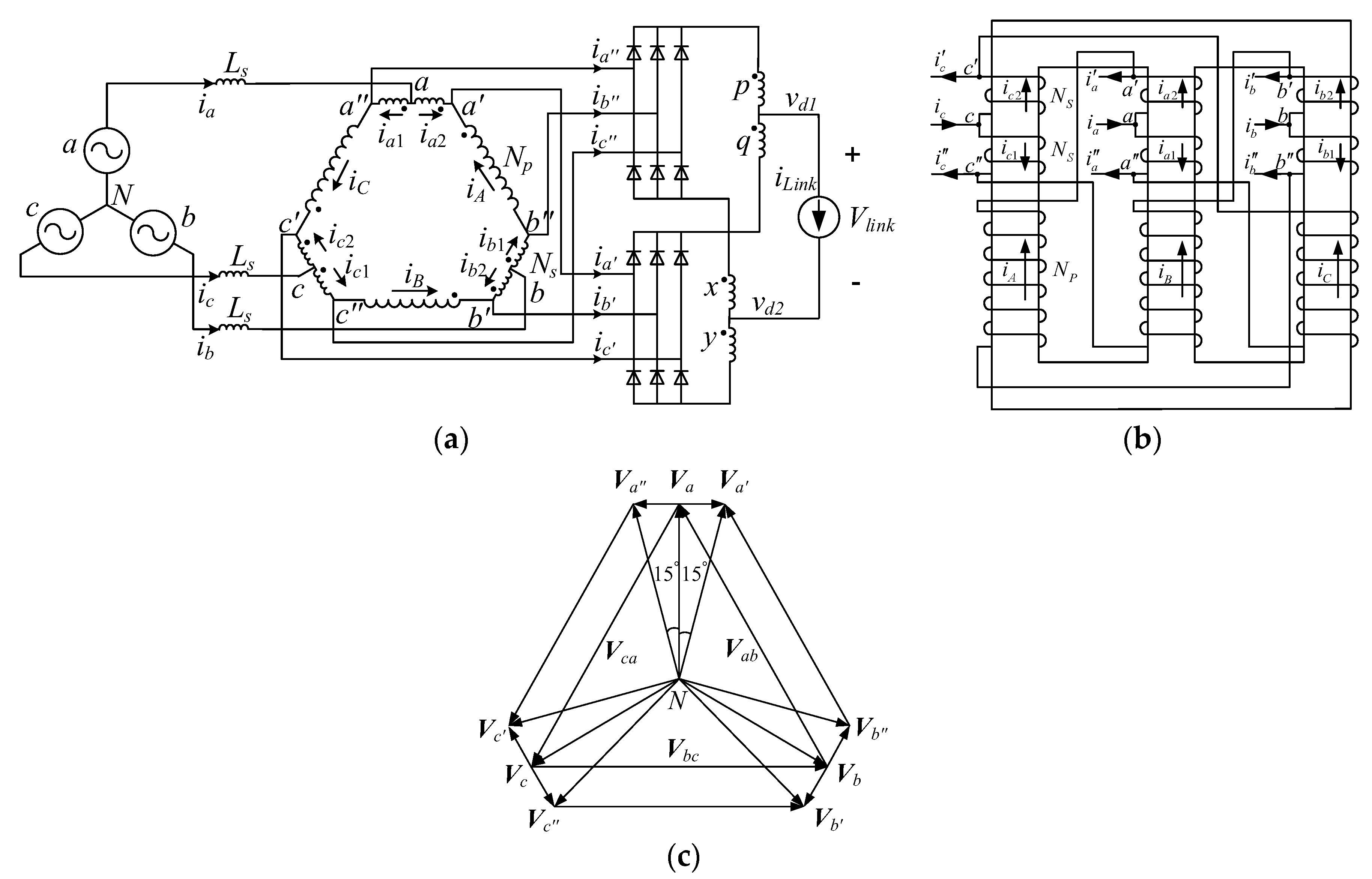
Figure 3.
Voltage waveforms of the studied 12-pulse auto-transformer rectifier unit (ATRU).

Figure 4.
Current waveforms of the studied 12-pulse auto-transformer rectifier unit (ATRU).

Figure 5.
System structure with proposed ATRU and modified overall power controller.

Figure 6.
Simplified control block diagram. (a) Maximum power point tracking (MPPT) operation mode; (b) constant speed (CS) operation mode; (c) constant power (CP) operation mode.
Figure 6.
Simplified control block diagram. (a) Maximum power point tracking (MPPT) operation mode; (b) constant speed (CS) operation mode; (c) constant power (CP) operation mode.

Figure 7.
Laboratory test-rig setup.
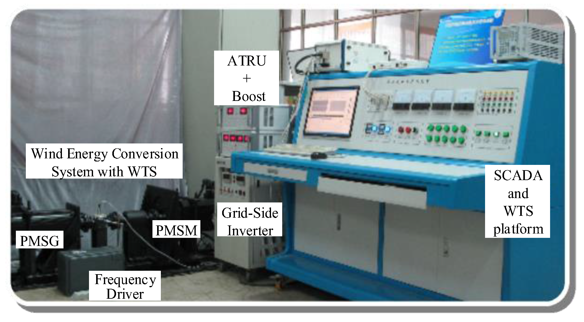
Figure 8.
System performances under step changing wind profile.

Figure 9.
Generator line voltage and phase current. (a) Waveforms; (b) Fast Fourier Transformation (FFT) analysis on the phase current.
Figure 9.
Generator line voltage and phase current. (a) Waveforms; (b) Fast Fourier Transformation (FFT) analysis on the phase current.

Figure 10.
Detected shaft torque with and without proposed method. (a) waveforms; (b) zoomed in torque waveforms inside the dotted area of Figure 10a.
Figure 10.
Detected shaft torque with and without proposed method. (a) waveforms; (b) zoomed in torque waveforms inside the dotted area of Figure 10a.

Figure 11.
System performances under dynamic wind profile.

© 2018 by the authors. Licensee MDPI, Basel, Switzerland. This article is an open access article distributed under the terms and conditions of the Creative Commons Attribution (CC BY) license (http://creativecommons.org/licenses/by/4.0/).
Share and Cite
MDPI and ACS Style
Chen, J.; Chen, J. On Reducing the Shaft Torque Ripple of Small-to-Medium-Scale Wind Energy Conversion Systems Using Multi-Pulse Autotransformer Rectifier. Energies 2018, 11, 379. https://doi.org/10.3390/en11020379
AMA Style
Chen J, Chen J. On Reducing the Shaft Torque Ripple of Small-to-Medium-Scale Wind Energy Conversion Systems Using Multi-Pulse Autotransformer Rectifier. Energies. 2018; 11(2):379. https://doi.org/10.3390/en11020379
Chicago/Turabian StyleChen, Jie, and Jiawei Chen. 2018. "On Reducing the Shaft Torque Ripple of Small-to-Medium-Scale Wind Energy Conversion Systems Using Multi-Pulse Autotransformer Rectifier" Energies 11, no. 2: 379. https://doi.org/10.3390/en11020379
Note that from the first issue of 2016, this journal uses article numbers instead of page numbers. See further details here.