1. Introduction
Renewable energy sources, such as wind and solar, are becoming reliable alternatives to fossil fuel. In order to integrate these renewable energies into the utility grid, distributed generation (DG) power systems have drawn much attention from academia, because of their effectiveness and reliability [
1,
2]. Due to the strong requirement of the high energy efficiency and the flexibility to operate in both the grid-connected and island modes, power electronic converters are typically used in DG application systems. DG systems should be able to inject high quality current into the grid to fulfill the grid interconnection standard [
3], which is often ensured by the current controller of a grid-connected inverter. In particular, the control system of a grid-connected inverter should be implemented in an economical manner, and its design process should be systematic and straightforward, for easiness to accept it in DG power systems.
The key aspect of utilizing a grid-connected inverter is to meet the interface standards as stated in [
4,
5], and to minimize the implementation cost of the DG systems. Formerly, the grid-connected inverter employs only L-type filter as a mean of suppressing current harmonics injected into the grid [
6,
7]. In recent years, however, LCL-type filters are more attractive than the L-type filter, due to the smaller physical size and better harmonic attenuation capability in spite of the control complexity. In order to preserve the power quality, the total harmonic distortion (THD) in injected current needs to meet certain standards, such as IEEE-519 or IEC 61000-3-2, which have been enacted for the purpose of satisfying the gird integration codes [
8].
Conventionally, to control grid-connected inverters, the linear controllers, such as the proportional-integral (PI) control, have been employed in the synchronous reference frame, due to their simplicity and stability [
9]. However, the conventional PI decoupling controller does not give proper performance in the inverter system having LCL filters. Even though this control scheme can ensure a moderate quality of injected current into the utility grid, the choice of controller gains often requires a process of trial and error [
10].
As other approaches, the proportional-resonant (PR) controller, the predictive controller [
11], and the repetitive feedback controller [
12,
13,
14] have been proposed in literature. The PR controllers have been widely used for grid-connected inverters, due to their capability to reject individual harmonics by introducing an infinite gain at a selected resonance frequency [
15,
16,
17,
18,
19,
20]. The implementation and evaluation of a typical PR current controller in an inverter system was reported in [
17,
18]. In order to consider the parameter variations, a direct discrete-time pole placement strategy was proposed in [
19] for the parameter design of a PR controller. In addition to the PR controller, an efficient hybrid damper for an LCL- or LLCL-filter has been presented for a single-phase grid-tied inverter, by using the capacitor current feedback to avoid the potential instability of system [
20]. By implementing multiple PR controllers, selected higher-order harmonics can be effectively rejected. However, the resonant controllers usually increase the complexity and calculation burden of the system.
On the other hand, predictive controllers give a satisfactory performance under the assumption that the system parameters are exactly known. This controller mimics the deadbeat control in the synchronous
dq-reference frame, and has the advantage of simple implementation. In order to minimize the resonant behavior during the grid connection, a predictive controller has been designed by using the discrete-time model of inverter system in the natural reference frame [
11].
A repetitive feedback control, which is based on the concept of iterative learning control, has been widely applied for many practical industrial systems. The research work in [
14] presented a repetitive control scheme, in which the inverter-side currents are regulated by the PI controllers, and the grid-side currents are controlled by a separate repetitive controller. Due to the use of the repetitive controller, considerable improvement under harmonically distorted grid voltage can be observed.
To further improve the robustness of inverter system, an H-infinity repetitive current controller has been presented [
21]. Since the parameter variations were taken into account in designing the controller by H-infinity approach, the robustness against the parameter variations of inverter system can be improved. Aside from the repetitive control scheme, a neural network vector controller has been presented for a single-phase grid-connected inverter [
22]. In this work, the controller was trained by the Levenberg-Marquardt algorithm, to eliminate the influence of coupling terms. However, it is worth mentioning that the use of learning mechanism in these controllers often gives slow dynamic response of the closed-loop system.
This paper proposes a systematic controller design methodology for a grid-connected inverter with LCL filter using a discrete-time integral state feedback control and state observer schemes. Generally, to implement the integral state feedback controller, the measurement of all system states should be required, which increases the cost and complexity of system, due to the necessity of additional sensors. To overcome such a limitation, this paper presents a systematic design procedure for a LCL-filtered grid-connected inverter in a discrete-time domain, by using the estimated states based on full-state observer. The proposed control scheme consists of an integral state feedback controller and a full-state observer which uses the control input, grid-side currents, and grid voltages to predict all the system state variables. The proposed control scheme ensures both the reference tracking and disturbance rejection performance of the inverter system by using only the measurement of the grid-side currents and grid voltages. This significantly reduces the cost and complexity of the LCL-filtered grid-connected inverter system in DG applications. In addition, the discrete-time integrator is also incorporated in the state feedback controller, which ensures an asymptotic reference tracking performance in practical and simple way. For the purpose of verifying the practical usefulness of the proposed control scheme in DG applications, the whole control algorithm has been implemented using the software of 32-bit floating-point digital signal processor (DSP) TMS320F28335 to control a 2 kW three-phase prototype grid-connected inverter [
23]. The feasibility and effectiveness of the proposed scheme are demonstrated through the comprehensive simulations and experiments. In addition to providing a systematic design methodology, the proposed control scheme can be a very practical approach of designing a grid-connected inverter in DG applications by virtue of its simplicity and low cost.
3. Design of a Discrete-Time Integral State Feedback Control with State Observer
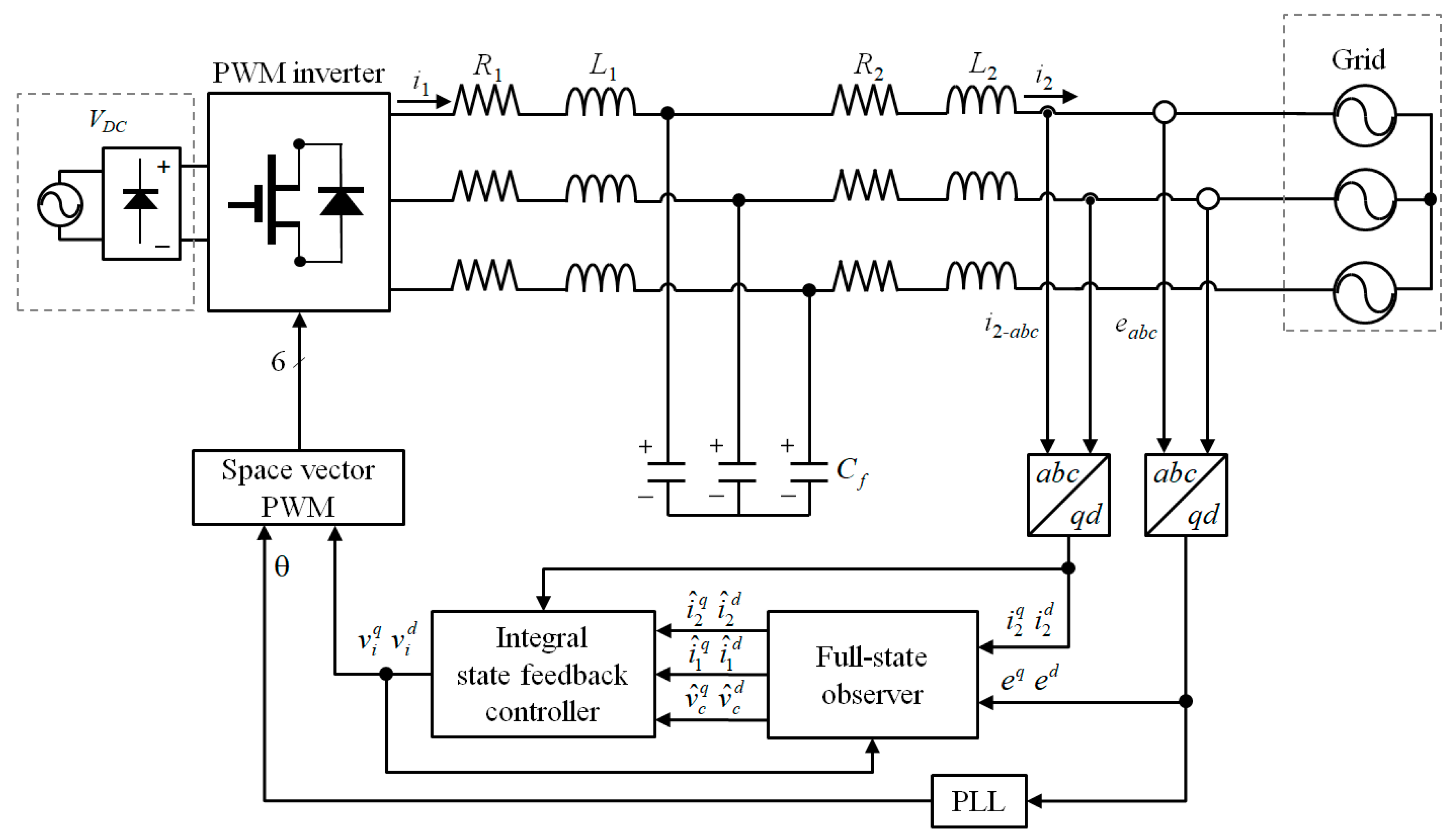
Figure 2 shows the block diagram of the proposed control scheme for a three-phase inverter connected to the grid through LCL filters, where the symbol “^” denotes the estimated quantities. The proposed control scheme basically consists of an integral state feedback controller, and a full-state observer with the measurement of only the grid-side currents and grid voltages. The measured grid voltages are also employed in the phase lock loop (PLL), to generate the phase angle of the grid voltage. The full-state observer is constructed by using an LCL-filtered inverter model to estimate the system states
from the control input
and the system output
y. Then, the estimated states are used for the integral state feedback controller to track the reference currents.
The system in (13) and (14) is controllable if, and only if, the controllability matrix
expressed as
has full rank. Since the rank of a matrix
is 6, the full-state vector is completely controllable. Similarly, the observable condition of the system in (13) and (14) can be investigated through the observability matrix as follows:
Since the rank of Po is 6, the full-state vector is completely observable.
One of the key tasks of the controller is to stabilize the inverter system, which can be accomplished by using a state feedback regulator. The control input of the state feedback regulator can be expressed as
where
K denotes the gain matrix of the state feedback regulator.
Generally, the state feedback regulator is unable to track the reference currents in the presence of the grid voltage disturbances and the variations of inverter parameters. Therefore, an integral control is introduced in this paper to assure the stable and robust operation of the inverter system. To construct the integral state feedback control, the discrepancy of the measured grid-side currents from their reference values can be given as
where
is the reference current vector and
is the current error vector. From (18), an integral action can be formulated in a state-space representation as follows:
The discrete-time representation of (19) can be obtained by using the discretization procedure presented in the previous section as follows:
The system in (20) can be augmented in the inverter system in (13) and (14) as
It can be observed from (21) and (22) that the asymptotic reference tracking is ensured as long as the augmented system is stabilized, i.e., the state
is derived to zero. For this purpose, a state feedback control is employed for this augmented system as follows:
where
is the gain vector, which can be systematically evaluated by using the pole placement method. Substituting (23) in (21), the state equation for the closed-loop system can be derived as follows:
The closed-loop system in (24) is stable if, and only if, all the eigenvalues of the equation as
lie within the unit circle. It is worth mentioning that the feedback controller in (23) requires the measurement for all the system states. However, this requirement often makes the system design costly and complicated. In order to avoid this limitation by implementing the integral state feedback controller by using the measurement of only the grid voltages and grid-side currents, a full-state observer is employed for the given system.
From the inverter system model in (13) and (14), the state equation of the full-state observer can be expressed as
where the symbol “^” denotes the estimated variables, and
G is the observer gain matrix. If the estimation error is defined as
, the error dynamics of the observer can be obtained by subtracting (26) from (13) as follows:
For the state observer to be stable, all the eigenvalues of the equation
should lie within the unit circle. Then, the state feedback control input can be constructed by using the estimated state variables as
The two gain vectors in (29) can be systematically evaluated by using the pole placement method. The selection of the observer poles requires a compromise between the rapidity of response and the sensitivity to measurement noise. The observer poles of
in the continuous-time domain can be transferred to the discrete-time domain through the transformation of
as follows:
Thus, if the observer poles in the continuous-time domain are determined, the pole locations in
z-domain, and thus, the observer gains can be easily obtained by the pole placement technique.
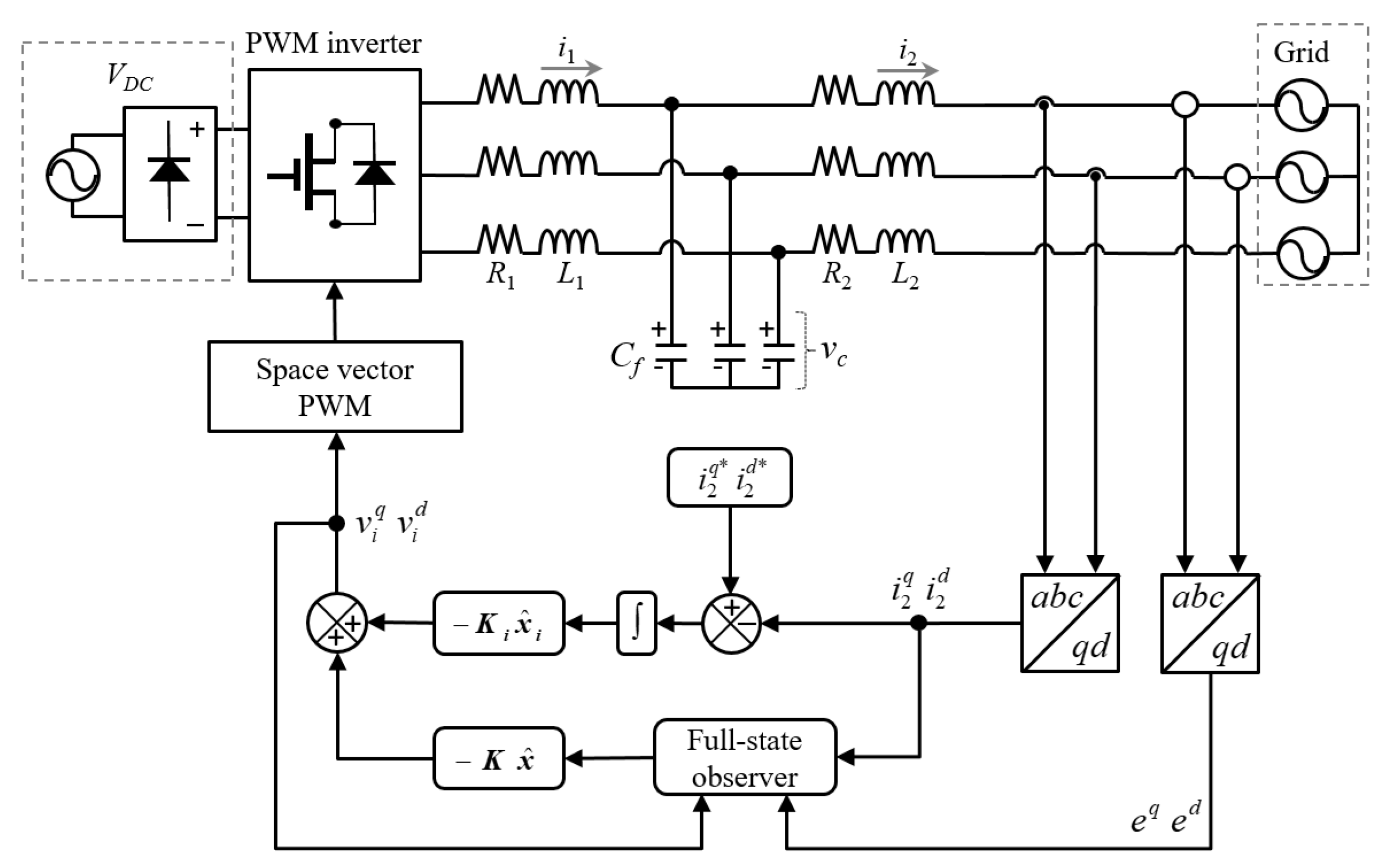
Figure 3 illustrates the control block diagram of the proposed integral state feedback control scheme in the discrete-time domain.
4. Simulation Results
In order to prove the feasibility of the proposed control scheme, the simulations have been carried out for an LCL-filtered three-phase grid-connected inverter using the PSIM software. The configuration of the inverter system and the proposed control scheme are depicted in
Figure 3. Also, the system parameters are summarized in
Table 1.
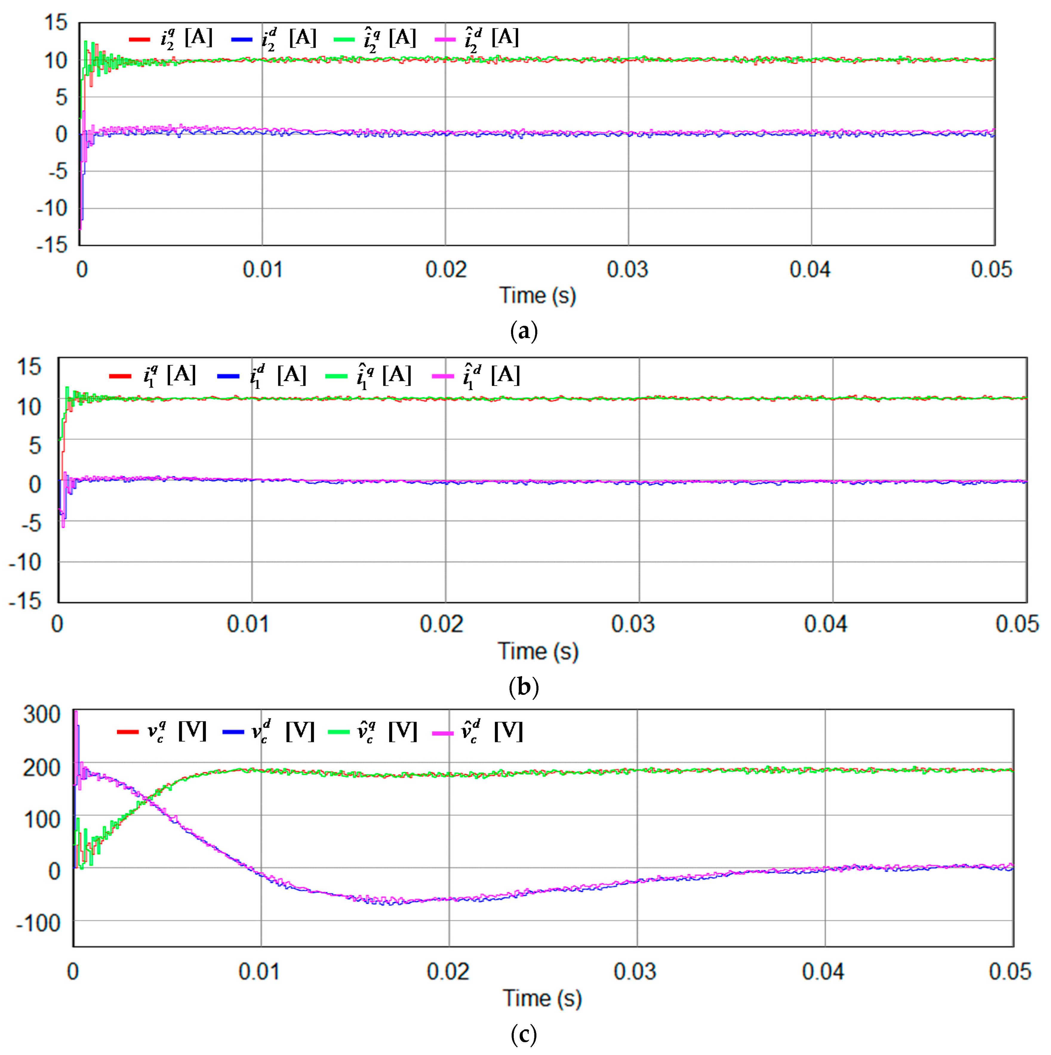
Figure 4 shows the simulation results for the inverter states and estimated states, using the proposed integral state feedback control scheme with state observer at the synchronous reference frame (SRF). To locate the observer closed-loop poles at the desired locations, the observer gains are chosen by using Matlab “place” function with inverter parameters. As can be observed from
Figure 4, the estimated states instantly converge to the actual ones, regardless of oscillations during initial transient periods. In this simulation, the phase lock loop (PLL) also starts its operation at
t = 0, to determine the phase angle of grid voltage. The large initial oscillation in the estimated states partly comes from the fact that the PLL requires sufficient time to be stabilized. After the PLL reaches the steady state, the estimated states will converge to the actual ones, which confirms a fast and stable operation of the observer. These estimated states are employed in (24) to constitute the integral state feedback control scheme in a discrete-time domain.
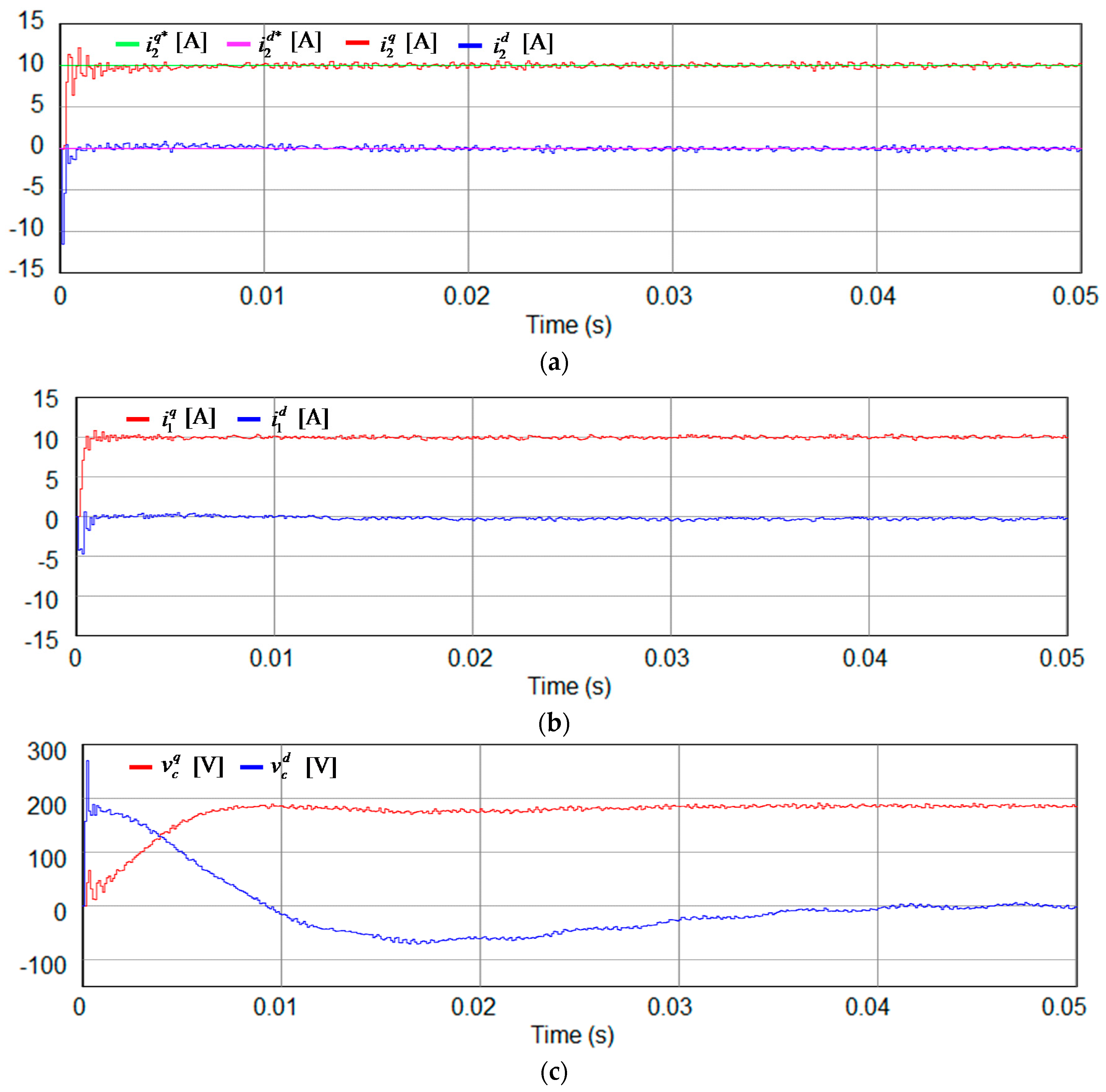
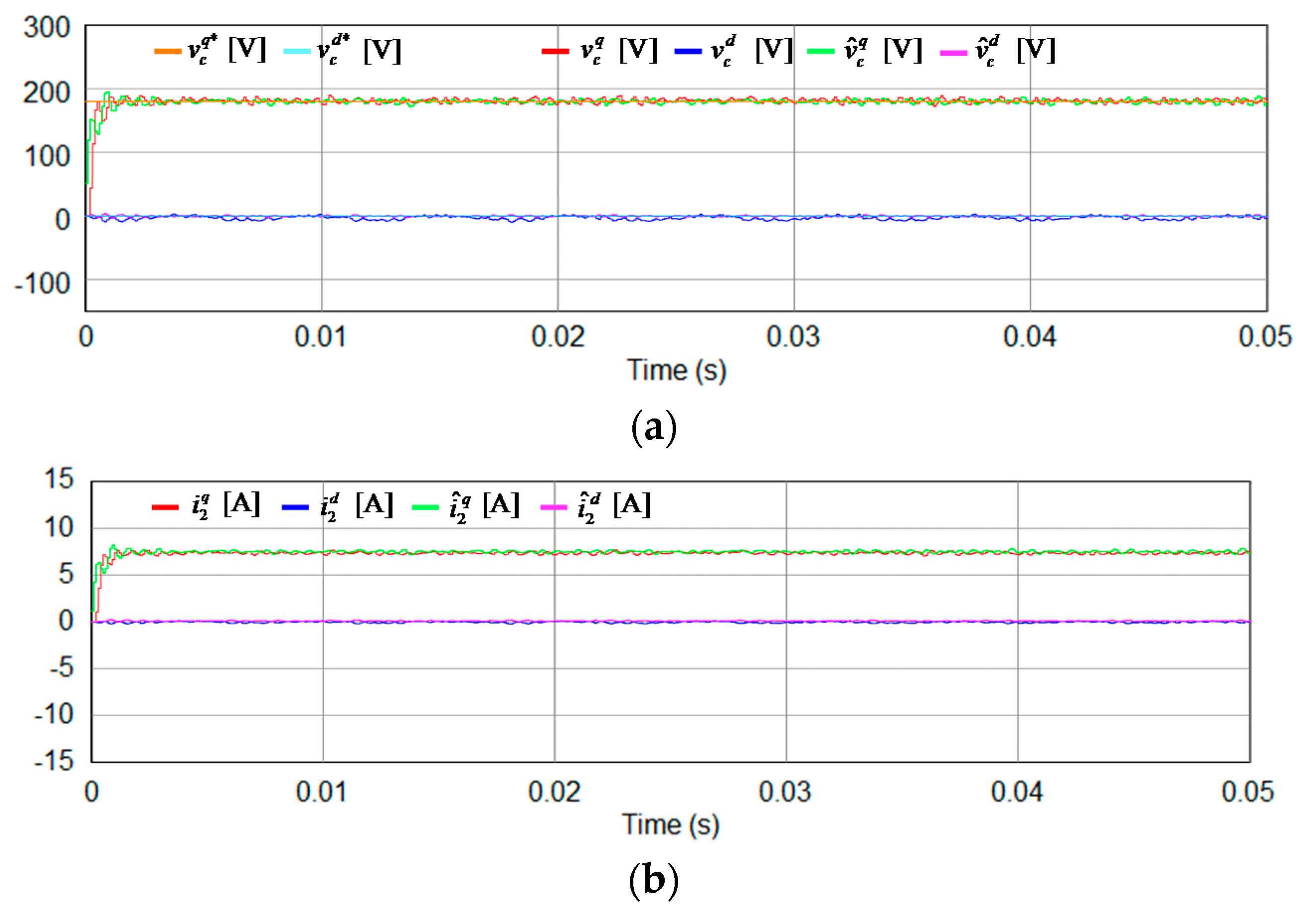
Figure 5 shows the simulation results for the proposed integral state feedback control scheme with state observer. Similarly, to place the closed-loop poles of the integral state feedback control scheme at the desired locations, the control gain matrices are chosen by using Matlab “place” function with inverter LCL parameters. As is shown in
Figure 5a, the grid-side currents
and
well track the reference currents at the SRF with satisfactory dynamic performance, without showing any steady-state errors or fluctuation. Even though the transient response of grid-side currents shows large settling time and some oscillations during start-up period, this is caused by the required time for the PLL to be stabilized. If the PLL reaches the steady state, the actual grid-side
q-axis current tracks the reference within 0.5 ms. Also,
Figure 5b,c represent the measured waveforms of the inverter-side currents and capacitor voltages at the SRF.
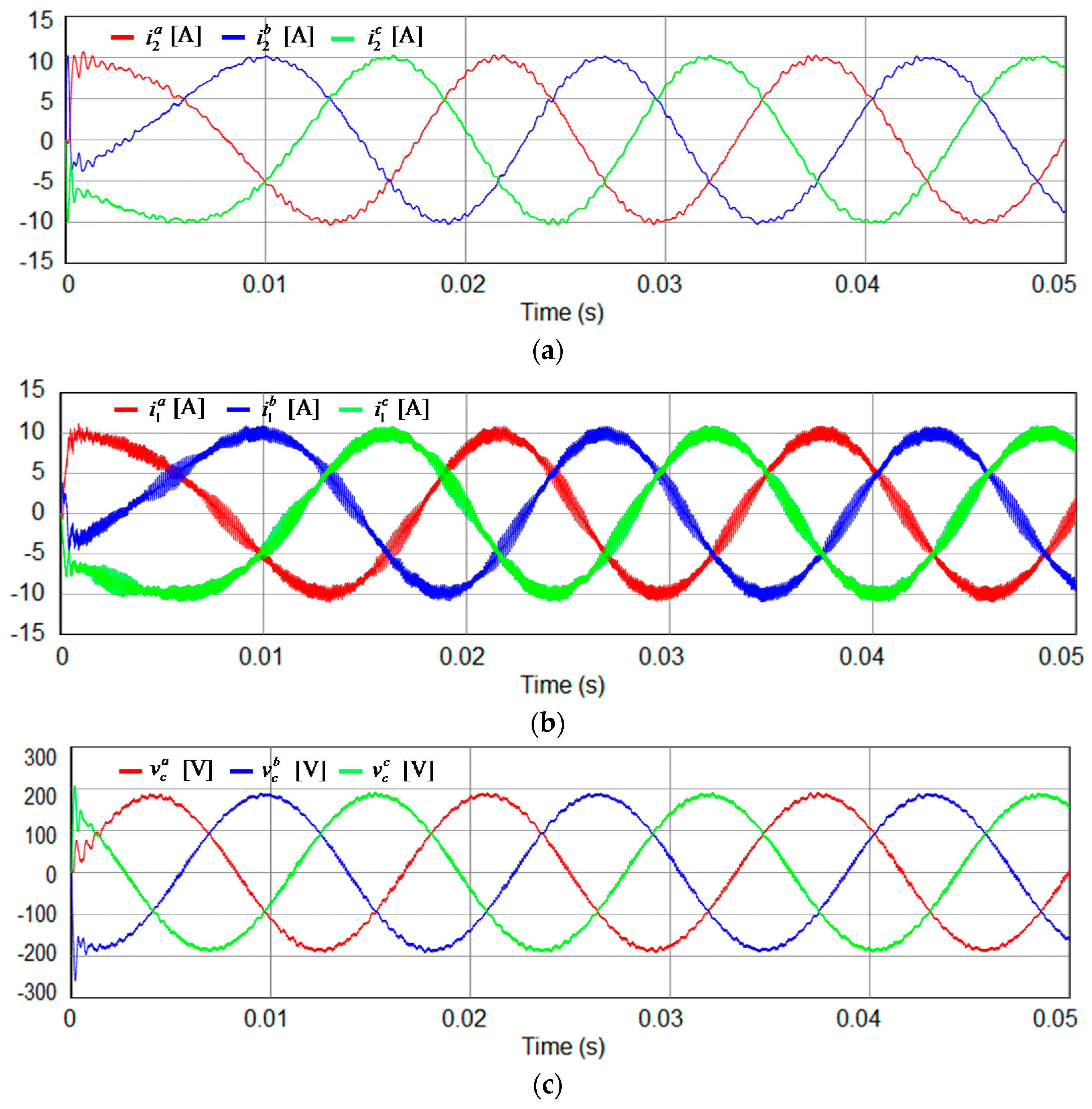
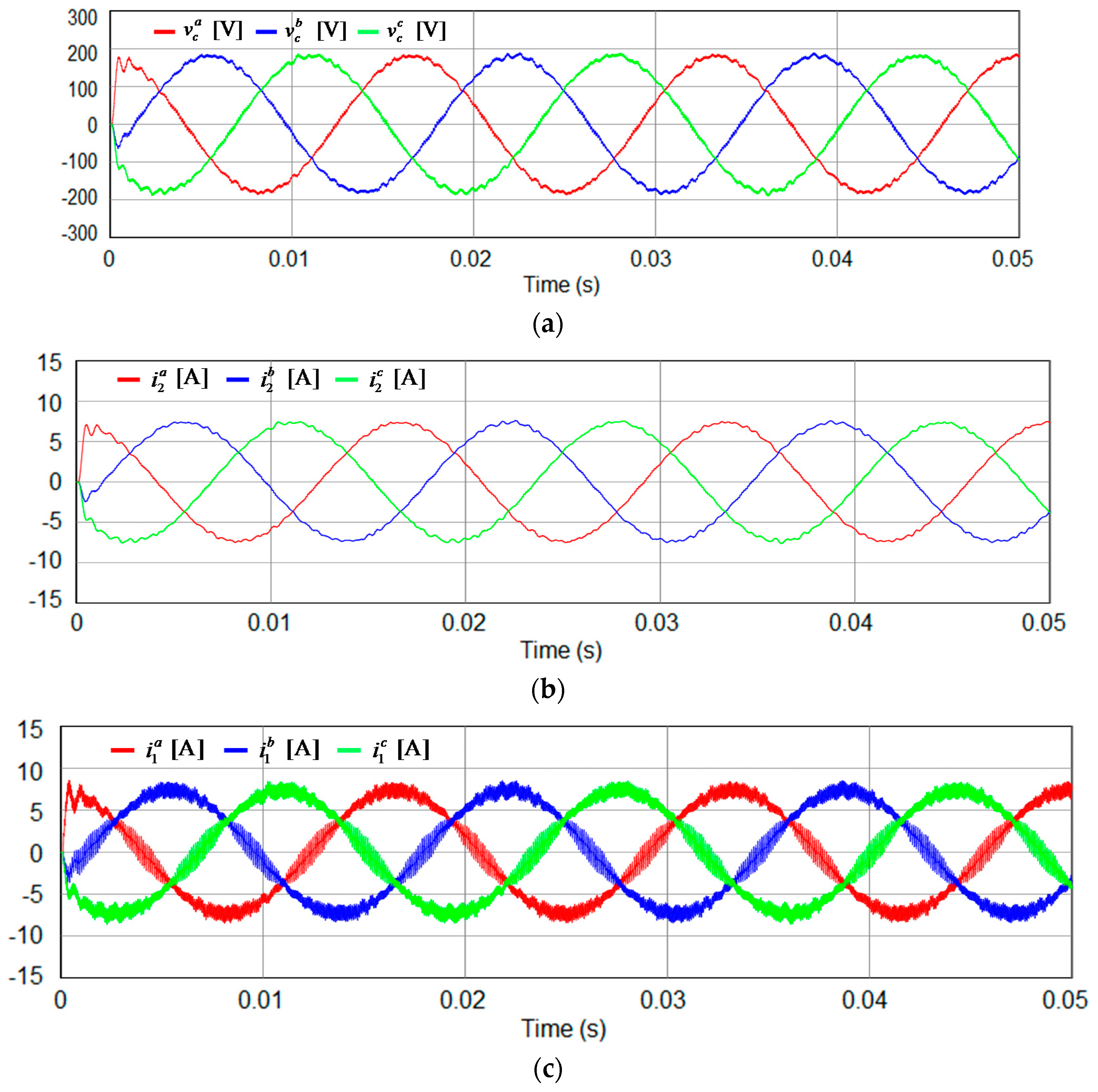
Figure 6 represents the simulation results for three-phase variables using the proposed integral state feedback control scheme with state observer. As can be seen from
Figure 6a, three-phase grid-side current waveforms are relatively sinusoidal. In fact, the grid-side phase currents have the THD level of 2.57% in this case. Also,
Figure 6b,c show actual three-phase inverter-side current waveforms and three-phase capacitor voltage waveforms.
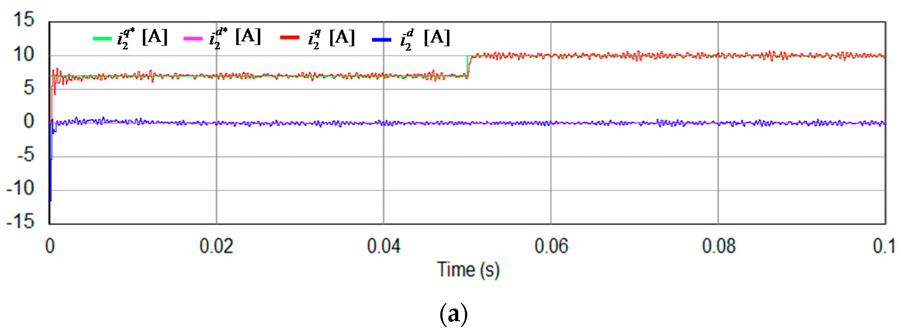
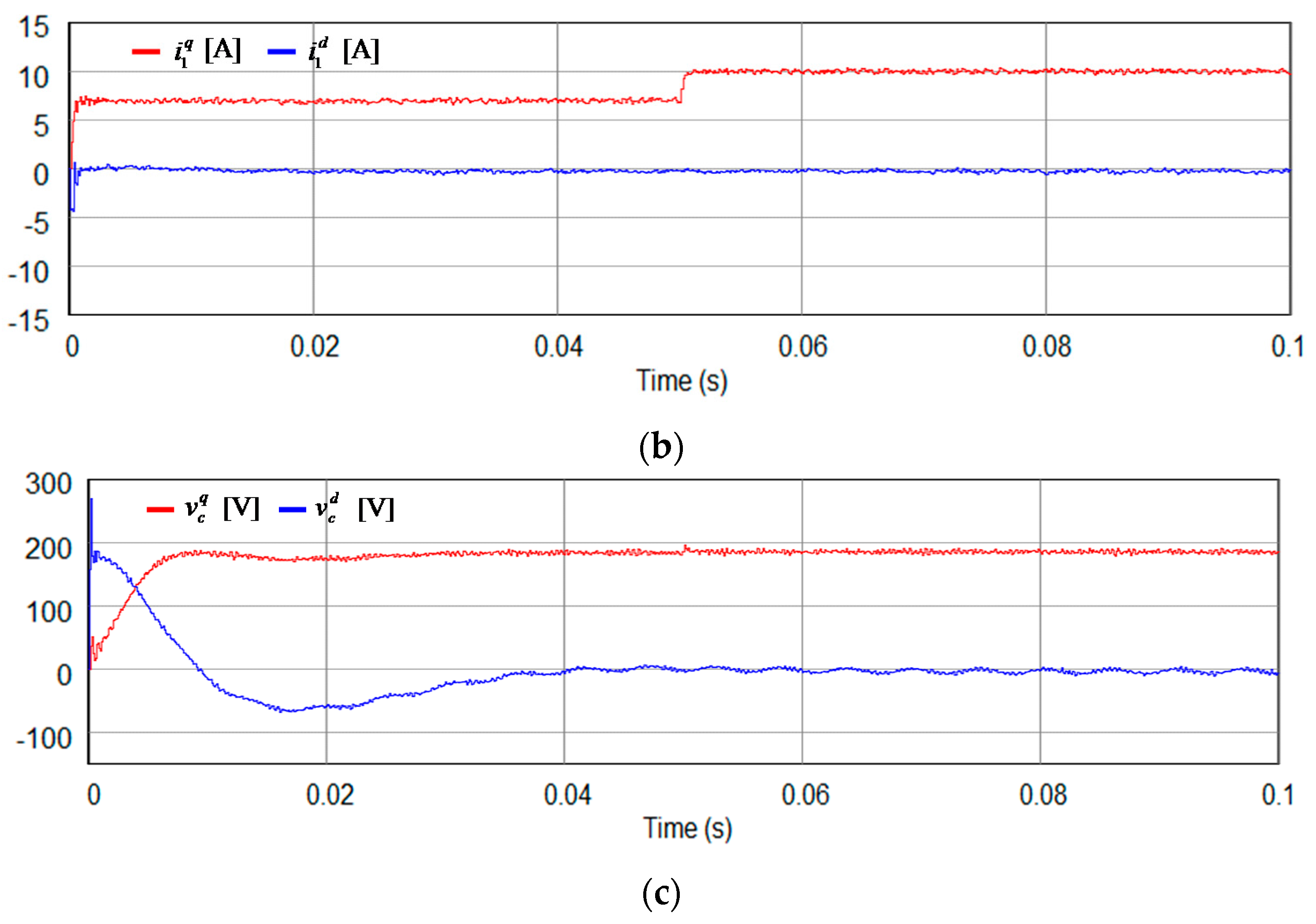
Figure 7 shows the simulation results for the proposed integral state feedback control scheme with state observer under the step change in
q-axis current reference. In this simulation, the
q-axis reference current undergoes a step change from 7 to 10 A at 0.05 s. It is clearly shown in
Figure 7a that the grid-side currents reach the reference current values with a considerably small time delay. Since the PLL already reached the steady state during start-up period, the grid-side
q-axis current can effectively track the step change in reference value within 0.5 ms, without showing such a large oscillation in this case. This indicates the sufficiently fast transient response of the proposed control scheme. Additionally, the fast transient response of the proposed control scheme can be inferred from
Figure 7b,c.
Figure 8 and
Figure 9 show the simulation results for the proposed discrete-time integral state feedback control scheme with state observer under islanding modes. In this operating mode, the capacitor voltages are controlled with their reference values to supply critical loads. One of the key roles of the grid-connected inverter is to ensure not only a stable operation of inverter, but also a continuous supply of electricity to critical loads. When the grid-connected inverter undergoes a sudden operation mode transition, the voltages at the point of common coupling often exhibit transient behavior. However, such a transient behavior is not desirable to critical loads. Furthermore, the grid-connected inverter is often required to operate continuously, even during islanding modes, to supply critical loads. The proposed control scheme has a benefit under this operation mode, since the capacitor voltages are continually estimated and can be controlled by using these estimated values, in case of need. It is confirmed from
Figure 8 and
Figure 9 that the proposed control scheme works well, even during islanding modes to supply critical loads.
5. Experimental Results
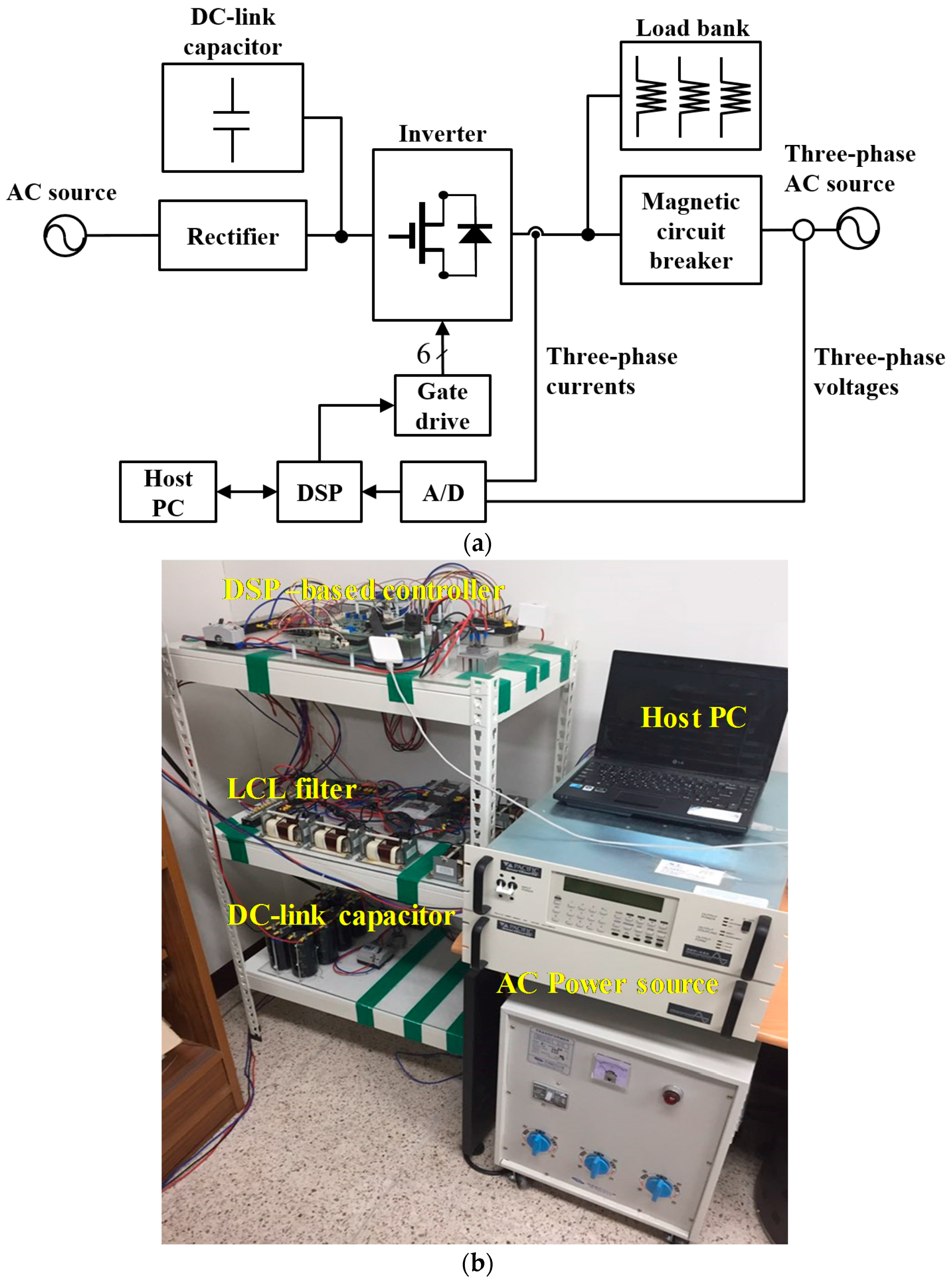
For the experimental validation of the proposed control scheme, the experimental setup has been constructed, which consists of a DSP-based controller, a three-phase inverter connected to the grid through an LCL filter, a magnetic contactor for grid connecting operation, and an AC power source to imitate three-phase grid voltages. The control algorithm is performed by a 32-bit floating-point DSP TMS320F28335 [
23], to control a 2 kW laboratory prototype inverter. The configuration of the entire experimental system is illustrated in
Figure 10a. An intelligent power module is employed for three-phase grid-connected inverter, and the switching frequency (sampling frequency) is chosen as 10 kHz.
Figure 10b shows the photograph of the experimental test setup.
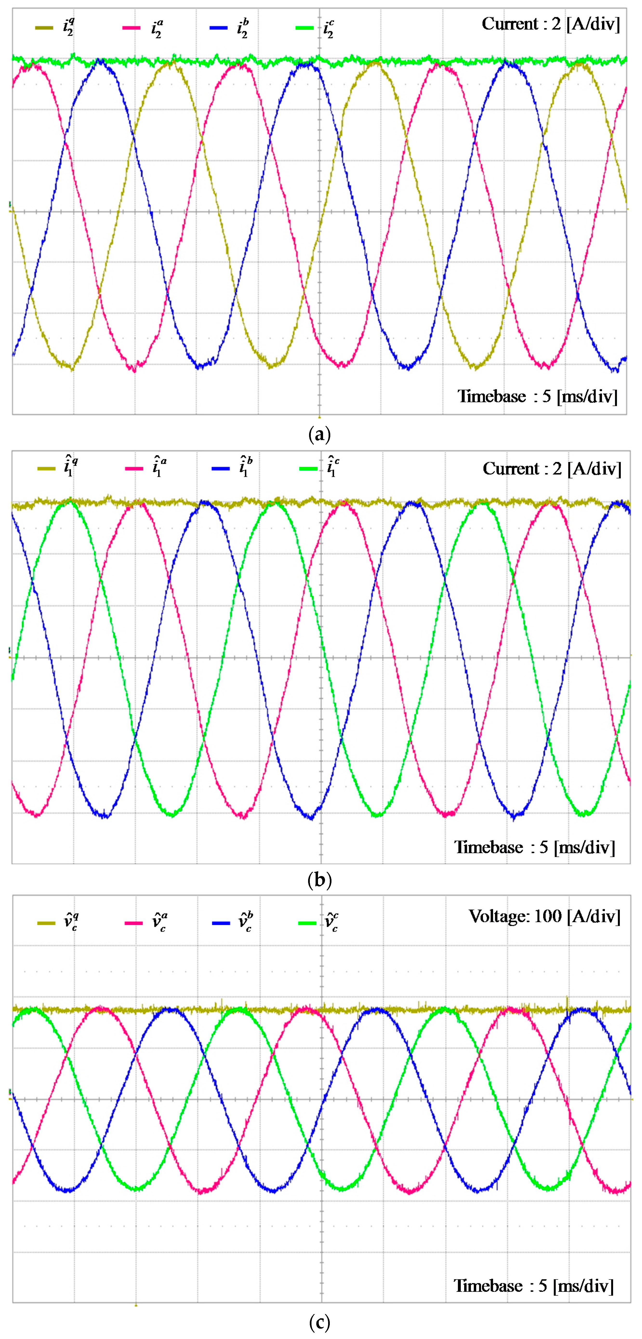
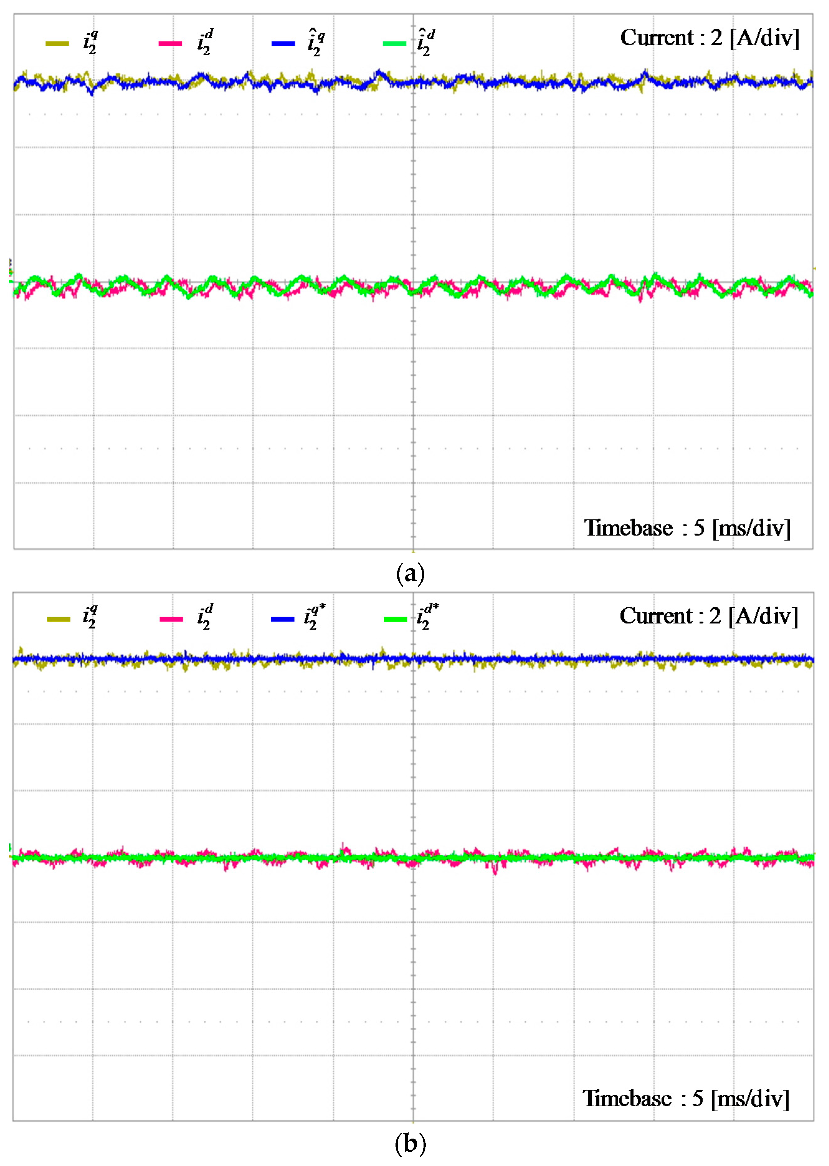
Figure 11 shows the experimental results for the inverter system using the proposed discrete-time integral state feedback control scheme with state observer. It can be observed from
q-axis and three-phase grid-side currents in
Figure 11a that the proposed control scheme provides stable and reliable operation for the inverter system with considerably sinusoidal responses of grid-side phase currents. Stable operation of the state observer can be also observed from
Figure 11b,c, in which inverter-side three-phase currents,
,
, and
, are calculated from the estimated currents
and
, and three-phase capacitor voltages,
,
, and
, from the estimated capacitor voltages
and
, respectively.
Figure 12 shows the experimental results for the grid-side current responses of the proposed control scheme, which proves that the experimental results are well consistent with the simulations in
Figure 4a and
Figure 5a. These results confirm a good performance of the proposed control scheme at steady state in practical realization.
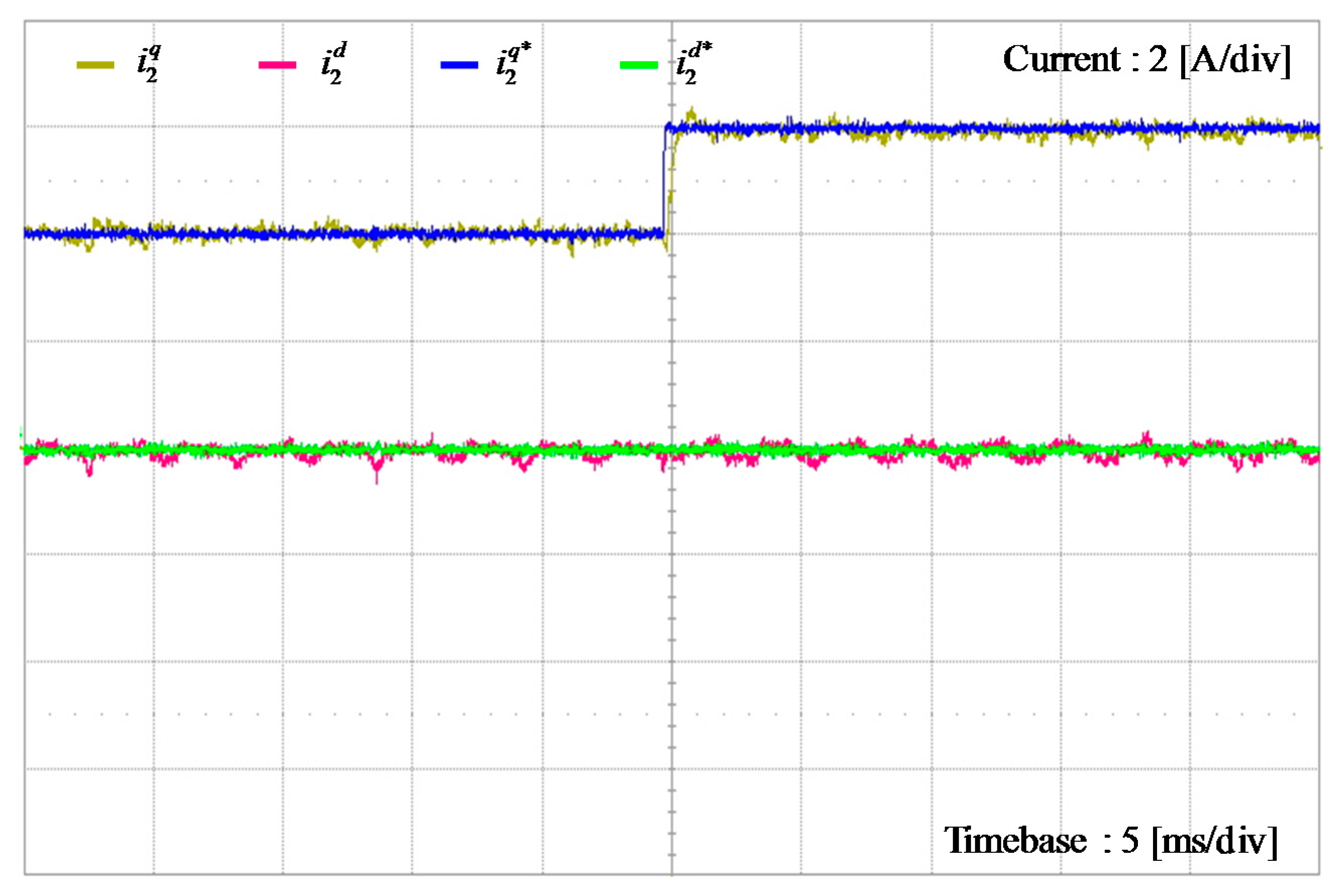
For the purpose of validating the proposed control scheme during transient state,
Figure 13 shows the experimental results of the proposed control scheme under the step change in grid-side
q-axis current reference, from 4 to 6 A. As is shown, the actual grid-side
q-axis current tracks the reference within 0.5 ms. It is clearly confirmed from this result that the grid-side current reaches the reference value with considerably small time delay, which accords well with the simulation result in
Figure 7.
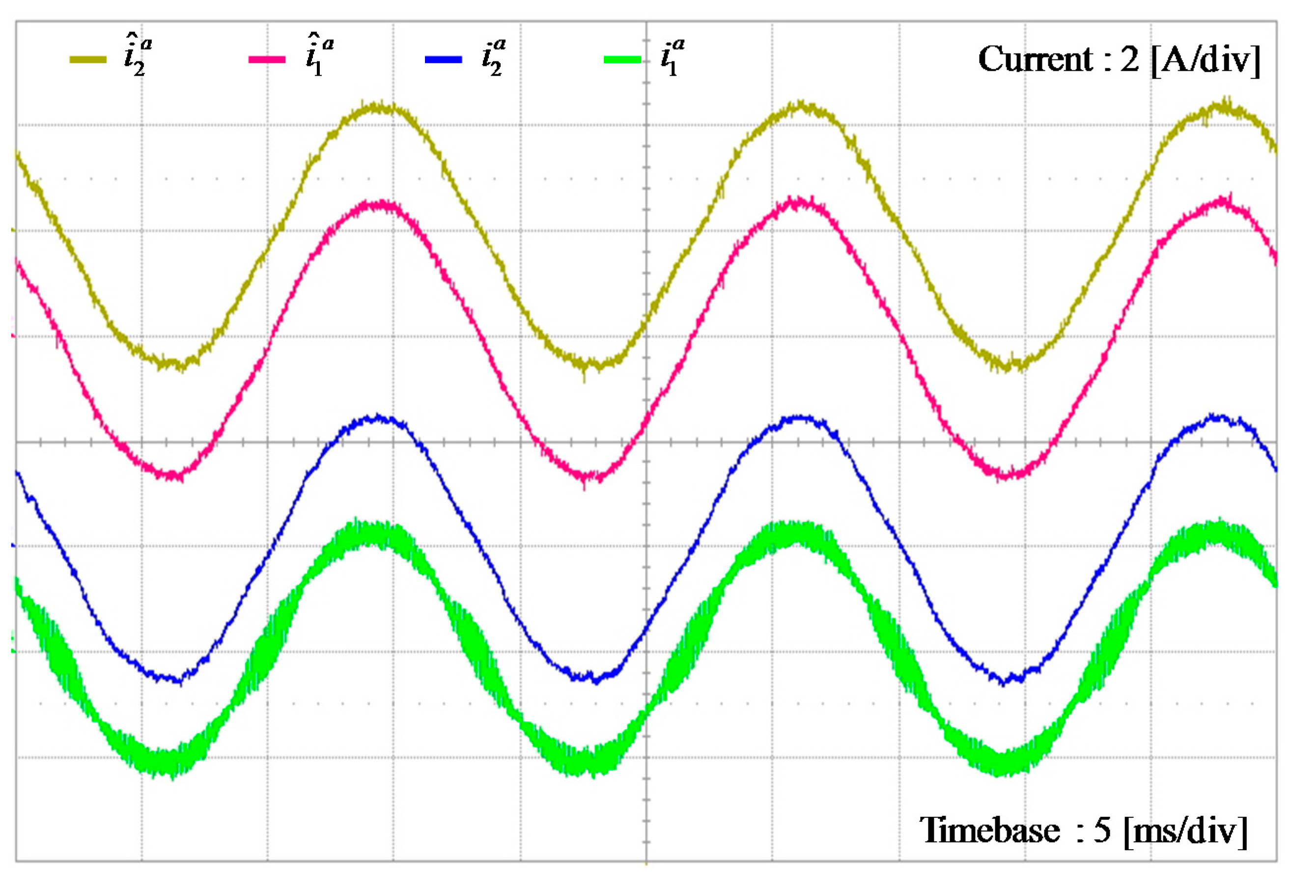
To assess the performance of the state observer,
Figure 14 shows the experimental results for the measured and estimated waveforms of
a-phase grid-side current and inverter-side current. From this figure, it can be observed that the estimated states well predict the actual states. Also, it is worth mentioning that the estimated states contain less harmonic components, due to high frequency switching.
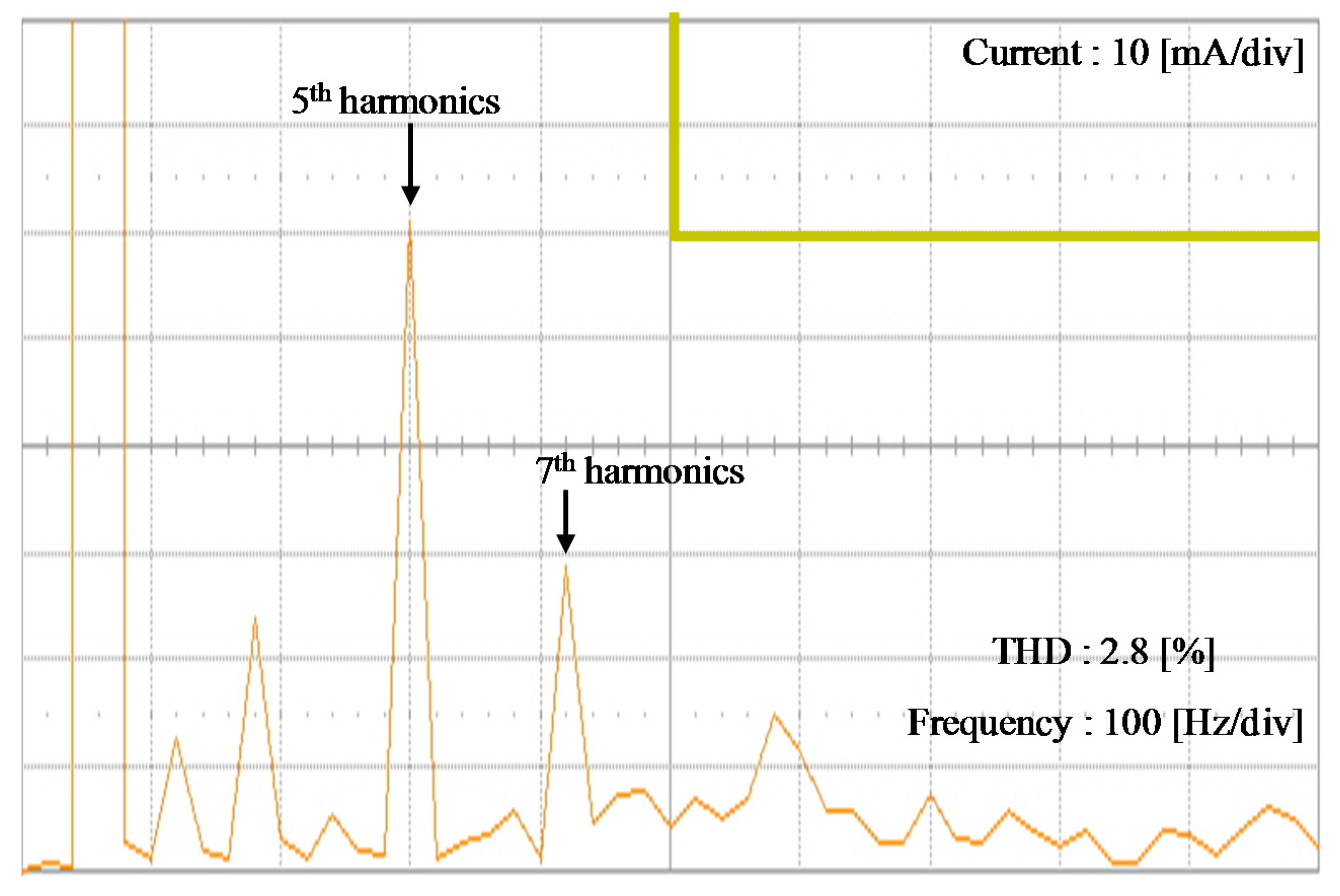
To evaluate the quality of injected currents by the proposed control scheme,
Figure 15 shows the fast Fourier transform (FFT) result for
a-phase grid-side current, together with the harmonic limits on IEEE Standard 519-1992. As can be observed, the THD level of injected current is relatively low. In fact, the injected current has the THD value of 2.8%, which successfully fulfills the interconnection standard harmonic according to IEEE Std. 1547.
6. Conclusions
In this paper, a systematic controller design methodology for a three-phase grid-connected inverter with LCL filter has been presented based on an integral state feedback control and state observer schemes in a discrete-time domain. To provide a comprehensive design procedure for an LCL-filtered grid-connected inverter, the design of the proposed control scheme consists of several steps. First, the accurate system model in the discrete-time domain is developed. Then, an integral state feedback controller is designed by using the discrete-time model. In general, to implement the integral state feedback controller, the measurement of all system states should be required, which increases the cost and complexity of system, due to the necessity of additional sensors. In order to reduce the number of sensors, a discrete-time full-state observer estimates both the inverter-side currents and capacitor voltages by using only the measured grid-side currents and grid voltages, which significantly reduces the cost and complexity of the LCL-filtered grid-connected inverter system in DG applications. In addition, the dynamics of output currents can be easily assigned by locating the closed-loop poles to desired values. Due to the discrete-time integrator incorporated in the state feedback controller, the proposed control scheme ensures both the reference tracking and disturbance rejection performance in a practical and simple way. Aside from the detailed analyses, the proposed scheme provides a systematic and straightforward controller design procedure.
To verify the practical usefulness of the proposed control scheme, a 2 kW prototype grid-connected inverter has been constructed, and the proposed control system has been implemented on 32-bit floating-point DSP TMS320F28335. Comprehensive simulation and experimental results are presented, to prove the feasibility and effectiveness of the proposed scheme. The transient response of the proposed scheme is very fast, having the settling time of about 0.5 ms. The injected currents by the proposed control scheme successfully fulfill the interconnection standard harmonic specified by IEEE Std. 1547, and have a low THD value of 2.8%. By virtue of simple and low-cost implementation, as well as systematic control design, the proposed control scheme can be a practical way of designing a grid-connected inverter in DG applications. In addition to providing a basic framework to synthesize a controller for a grid-connected inverter in a discrete-time state space, the proposed work can contribute to promote succeeding research studies, such as the optimal control design or grid frequency-adaptive control, because they are often designed in a discrete-time state model.


