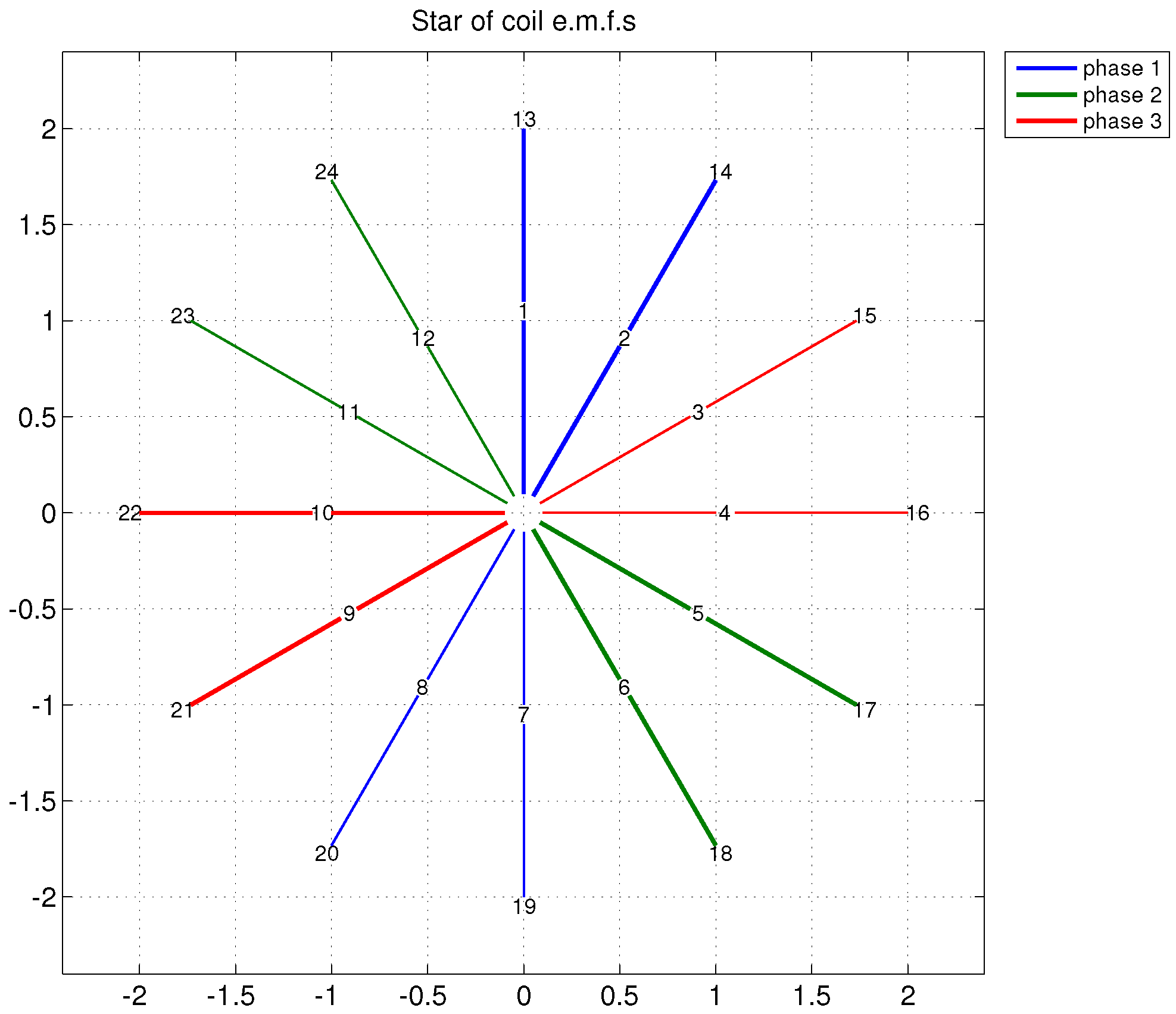
Figure 1.
Plot of the EMF star for a symmetrical winding with , and .
Figure 1.
Plot of the EMF star for a symmetrical winding with , and .
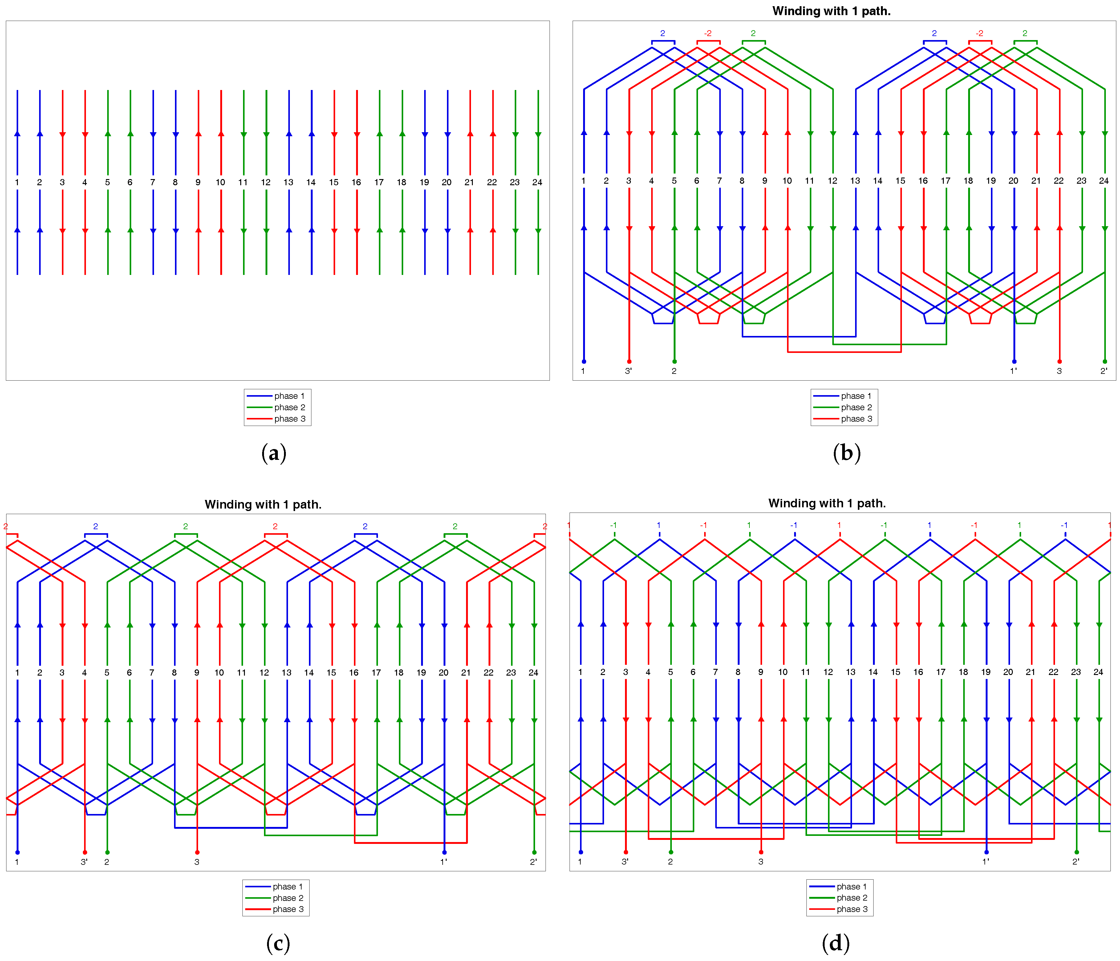
Figure 2.
Winding schemes with different end winding layouts for a single-layer configuration with , , and derived from the WDT. (a) Without end connections; (b) for a split stator and three-plane end winding; (c) with two-plane end winding and (d) with three-plane end winding.
Figure 2.
Winding schemes with different end winding layouts for a single-layer configuration with , , and derived from the WDT. (a) Without end connections; (b) for a split stator and three-plane end winding; (c) with two-plane end winding and (d) with three-plane end winding.
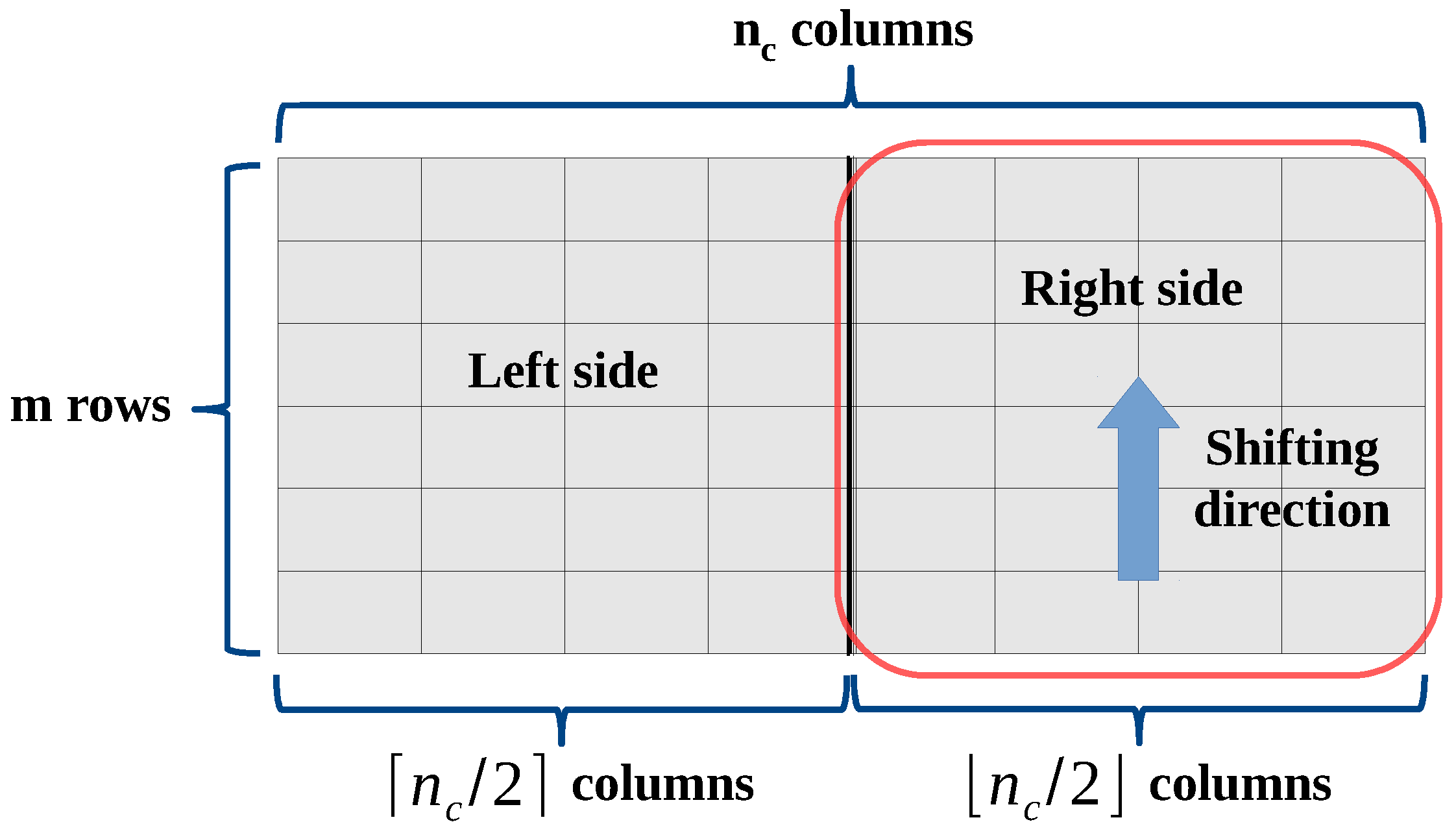
Figure 3.
WDT for a generic normal system winding. The right side of WDT is shifted upwards by steps.
Figure 3.
WDT for a generic normal system winding. The right side of WDT is shifted upwards by steps.
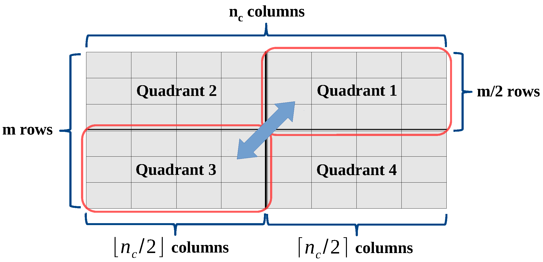
Figure 4.
Swapping of the WDT quadrants in case of reduced systems and .
Figure 4.
Swapping of the WDT quadrants in case of reduced systems and .
Figure 5.
A possible WDT for single phase windings.
Figure 5.
A possible WDT for single phase windings.
Figure 6.
(a) Slot EMF star for a symmetrical single-layer coil winding and (b) winding scheme. , , , and .
Figure 6.
(a) Slot EMF star for a symmetrical single-layer coil winding and (b) winding scheme. , , , and .
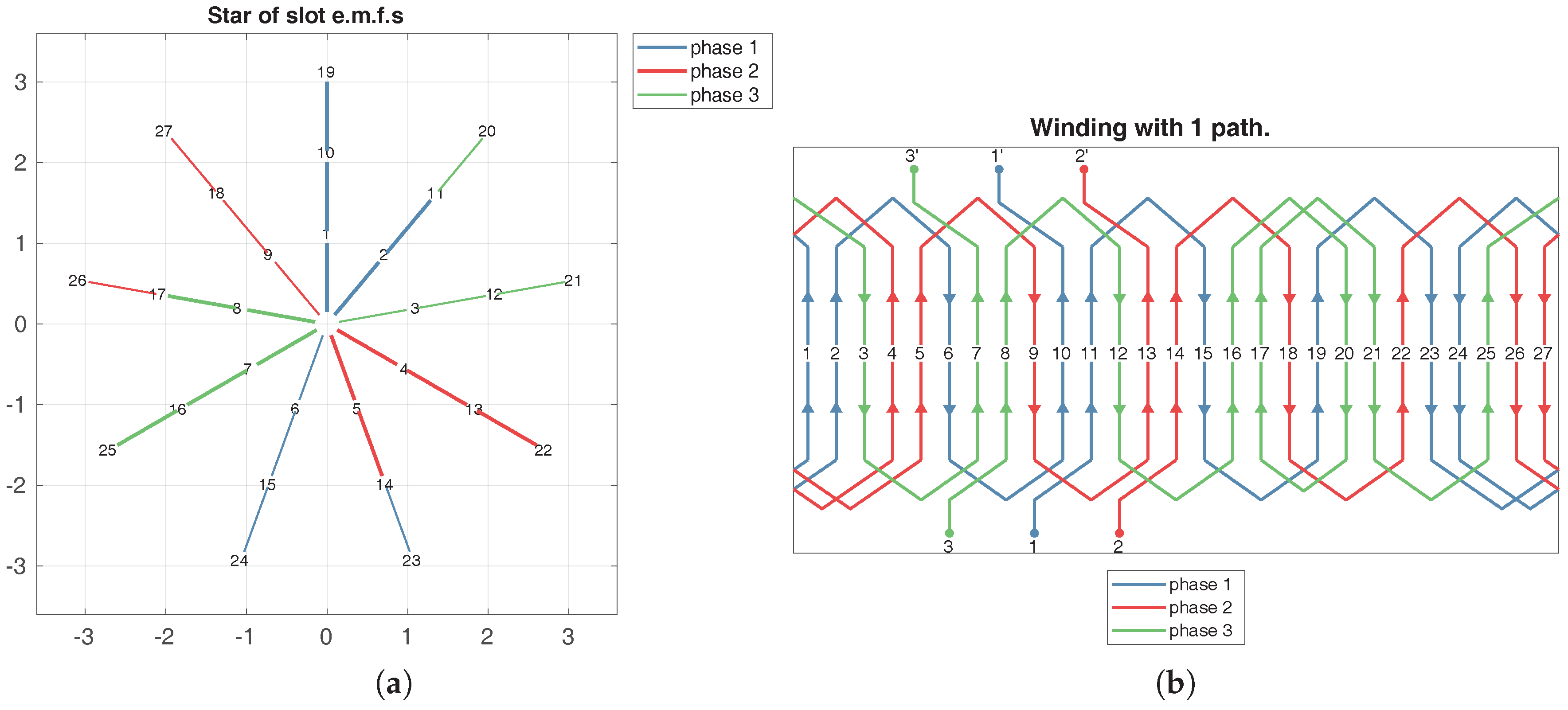
Figure 7.
(a) Slot EMF star for a symmetrical single-layer bar winding and (b) winding scheme. , , and .
Figure 7.
(a) Slot EMF star for a symmetrical single-layer bar winding and (b) winding scheme. , , and .
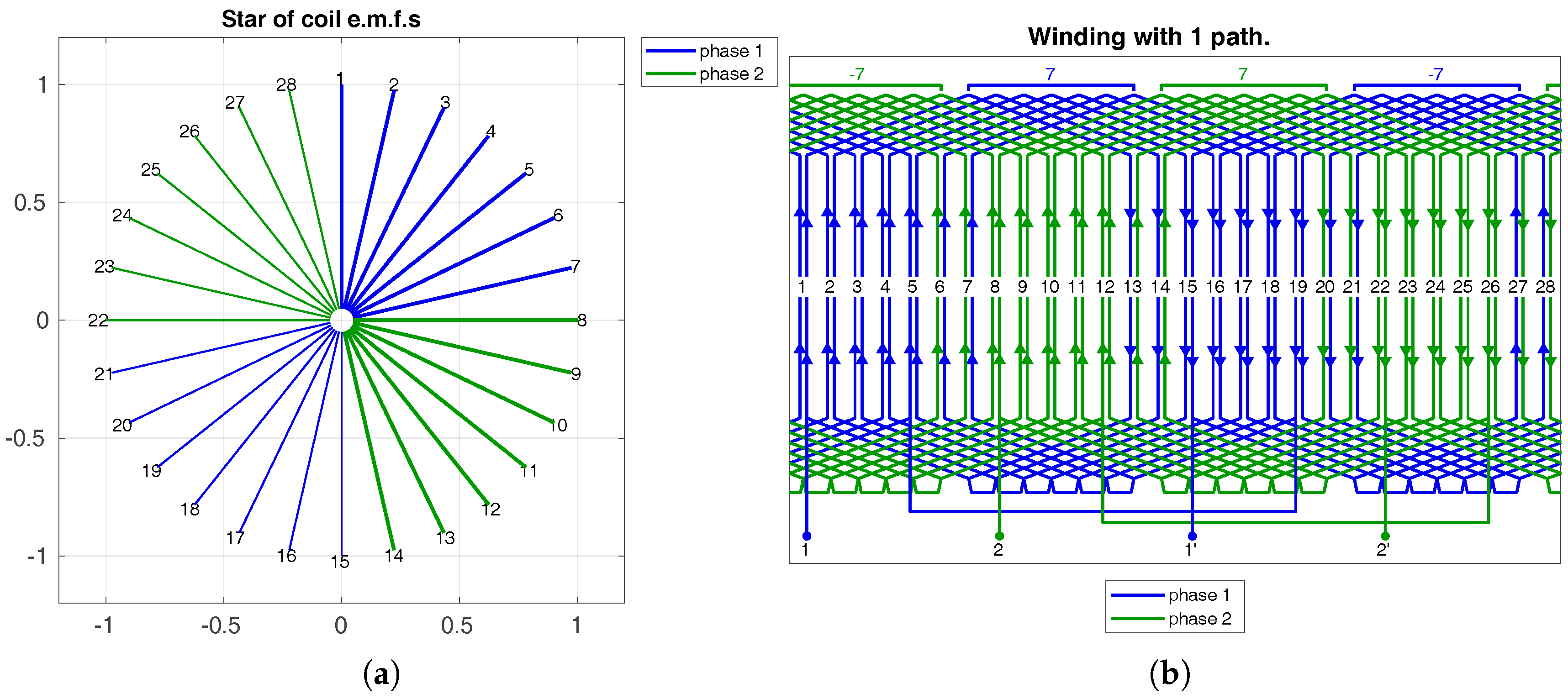
Figure 8.
(a) Coil EMF star for a symmetrical double-layer coil winding and (b) winding scheme with series connected paths. , , , and .
Figure 8.
(a) Coil EMF star for a symmetrical double-layer coil winding and (b) winding scheme with series connected paths. , , , and .
Figure 9.
(a) Star of slots and (b) winding configuration for a double-layer, three-phase concentrated winding with , and .
Figure 9.
(a) Star of slots and (b) winding configuration for a double-layer, three-phase concentrated winding with , and .
Figure 10.
(a) EMF star and (b) winding scheme for a symmetrical single layer non-reduced winding with , , and .
Figure 10.
(a) EMF star and (b) winding scheme for a symmetrical single layer non-reduced winding with , , and .
Figure 11.
(a) EMF star and (b) winding scheme of a double layer reduced symmetrical configuration with , , and .
Figure 11.
(a) EMF star and (b) winding scheme of a double layer reduced symmetrical configuration with , , and .
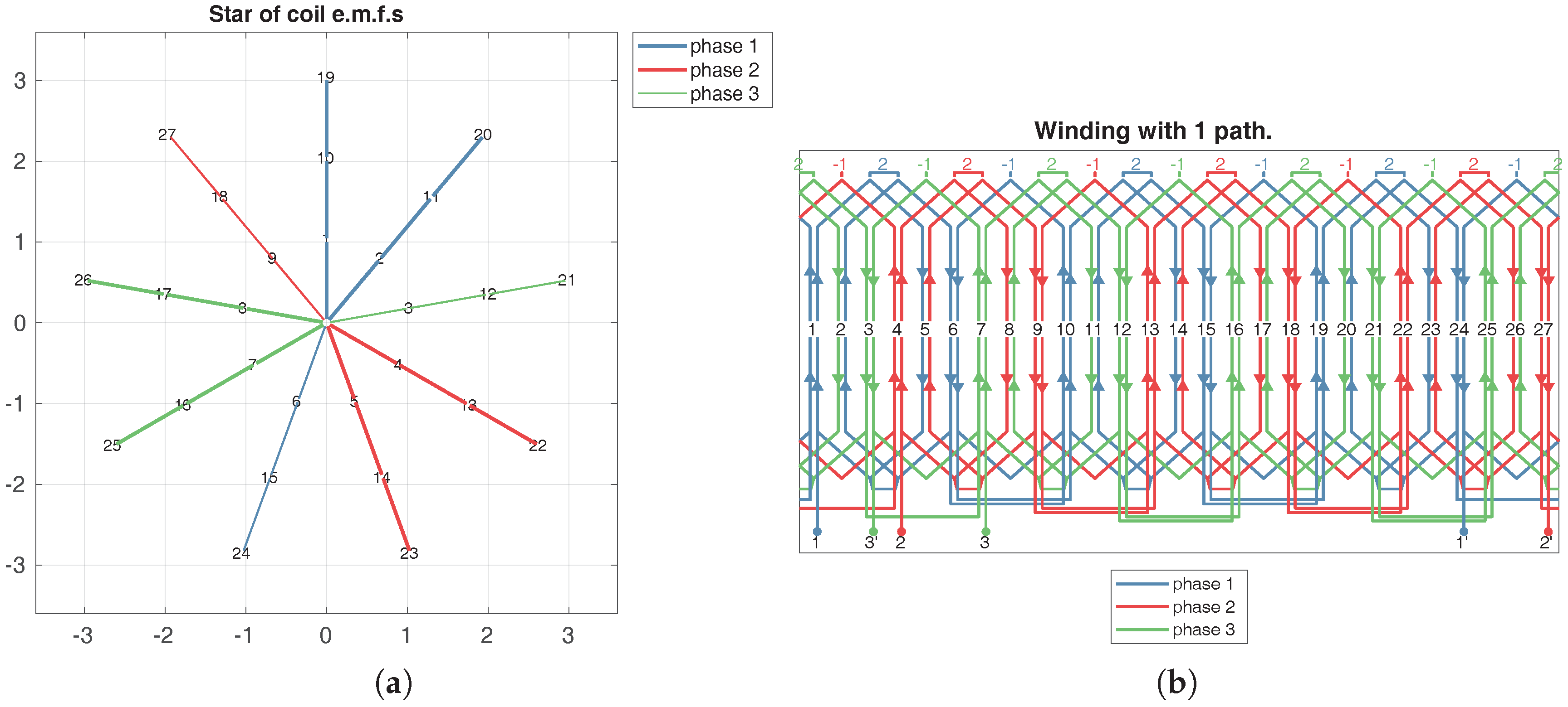
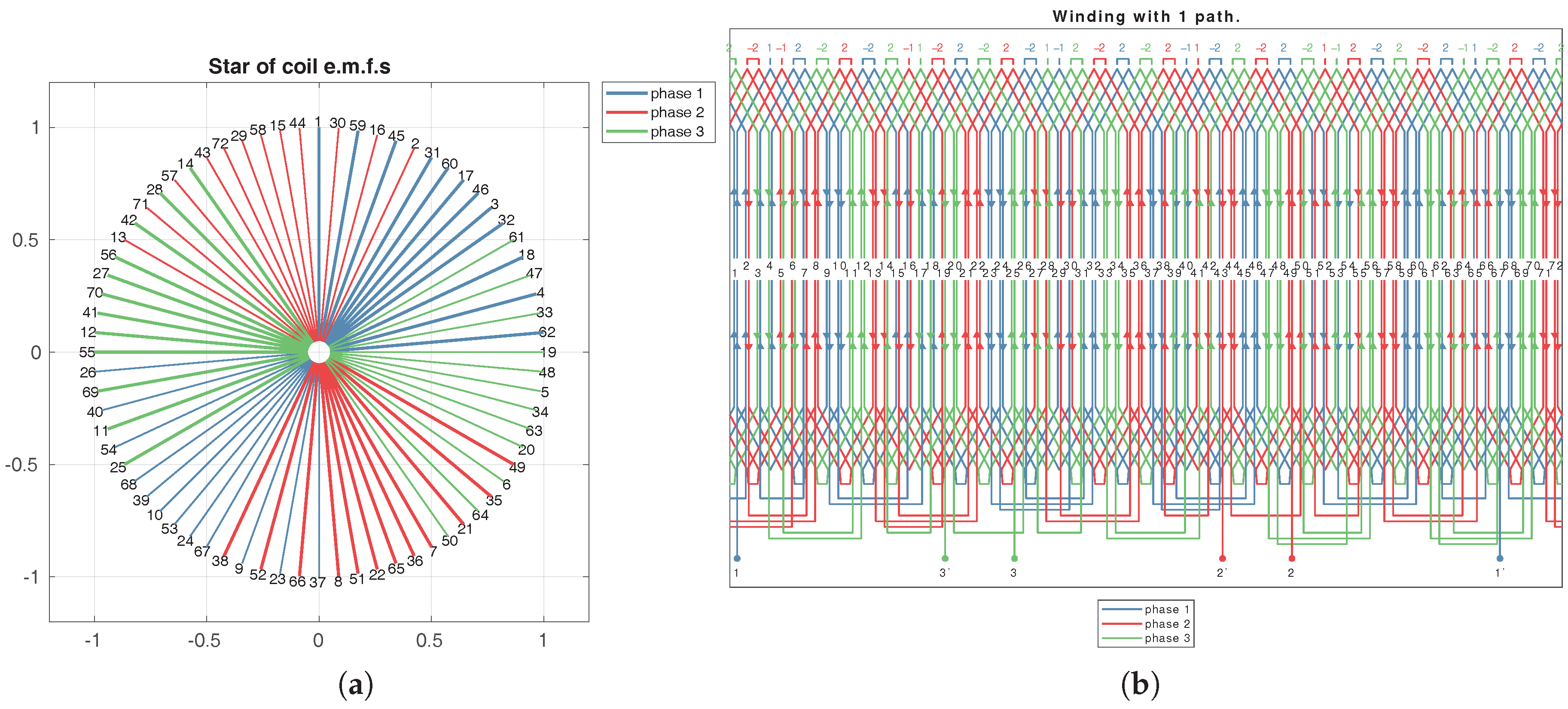
Figure 12.
(a) Star of coils EMF and (b) Winding scheme for , , , and .
Figure 12.
(a) Star of coils EMF and (b) Winding scheme for , , , and .
Figure 13.
Double layer seven-phase symmetrical winding with , , , and . (a) Star of slots and (b) winding scheme.
Figure 13.
Double layer seven-phase symmetrical winding with , , , and . (a) Star of slots and (b) winding scheme.
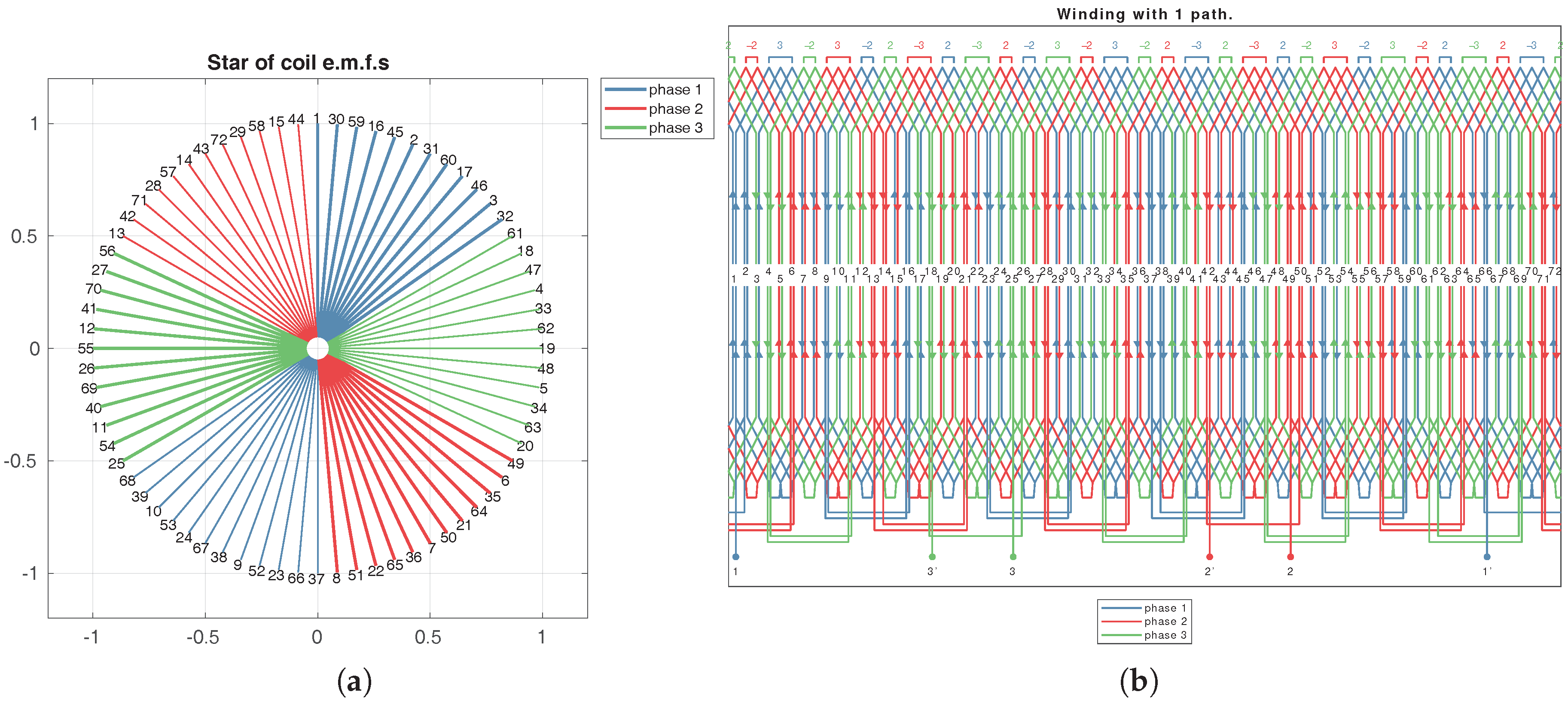
Figure 14.
Three-phase symmetrical winding with , , and . (a) Star of slots and (b) winding scheme.
Figure 14.
Three-phase symmetrical winding with , , and . (a) Star of slots and (b) winding scheme.
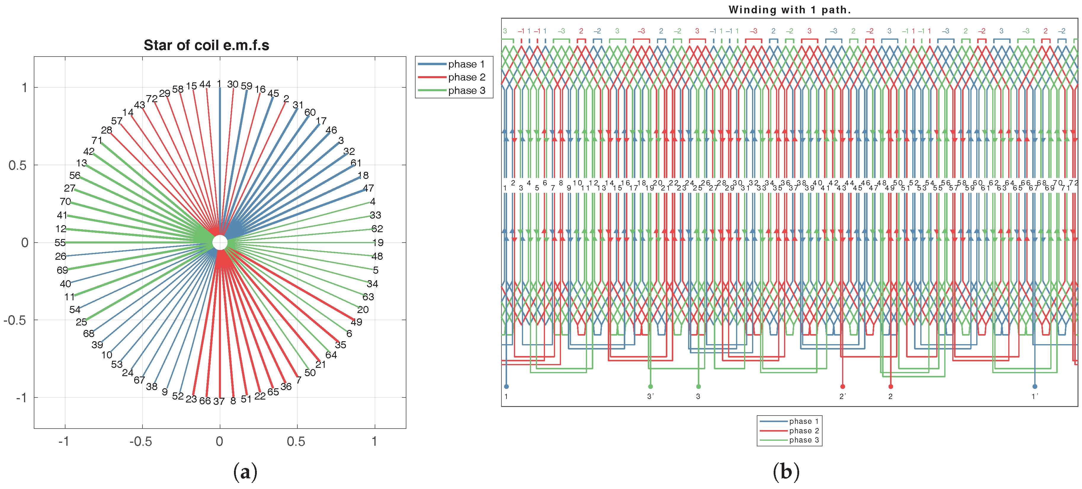
Figure 15.
Double chording with a 3rd-order single-sided imbrication for , , and . (a) Star of slots and (b) winding scheme.
Figure 15.
Double chording with a 3rd-order single-sided imbrication for , , and . (a) Star of slots and (b) winding scheme.
Figure 16.
Double chording with a 3rd-order double-sided imbrication for , , and . (a) Star of slots and (b) winding scheme.
Figure 16.
Double chording with a 3rd-order double-sided imbrication for , , and . (a) Star of slots and (b) winding scheme.
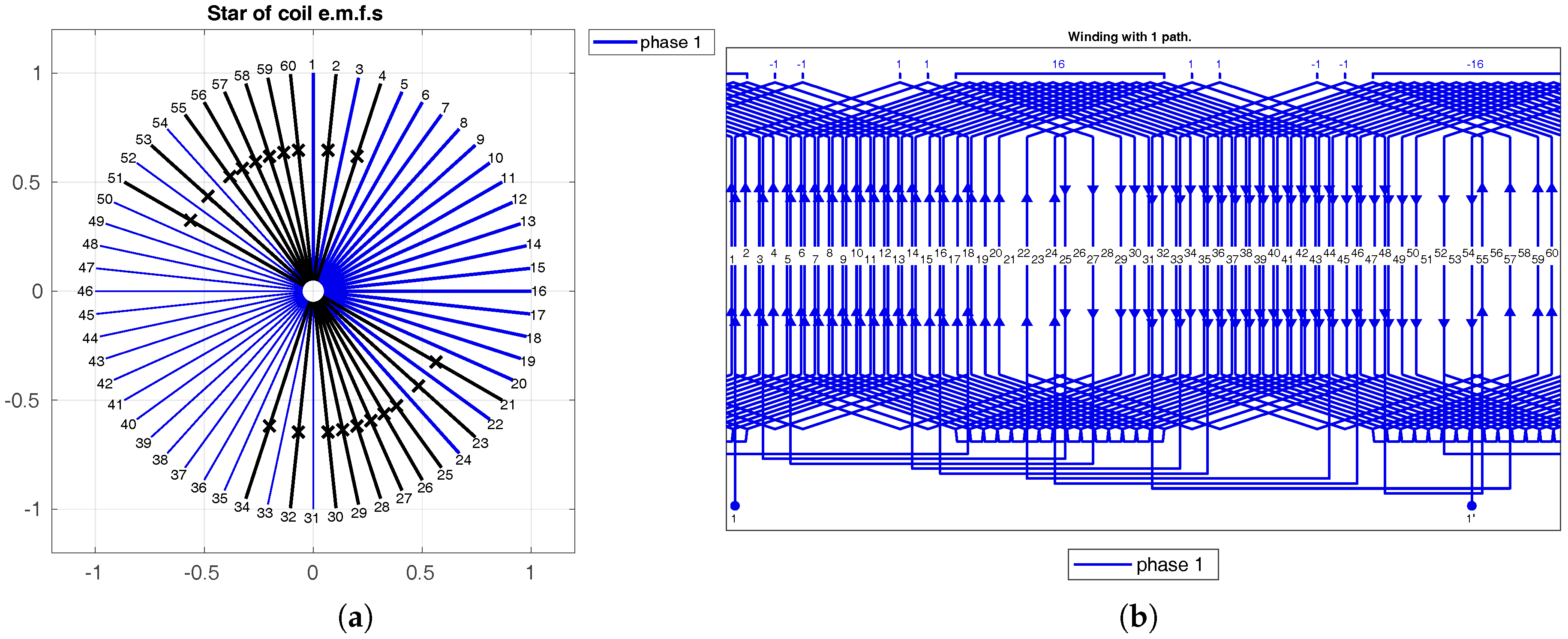
Figure 17.
Single phase winding with double chording, 2nd order double-sided imbrication for , , and . (a) Star of slots and (b) winding scheme.
Figure 17.
Single phase winding with double chording, 2nd order double-sided imbrication for , , and . (a) Star of slots and (b) winding scheme.
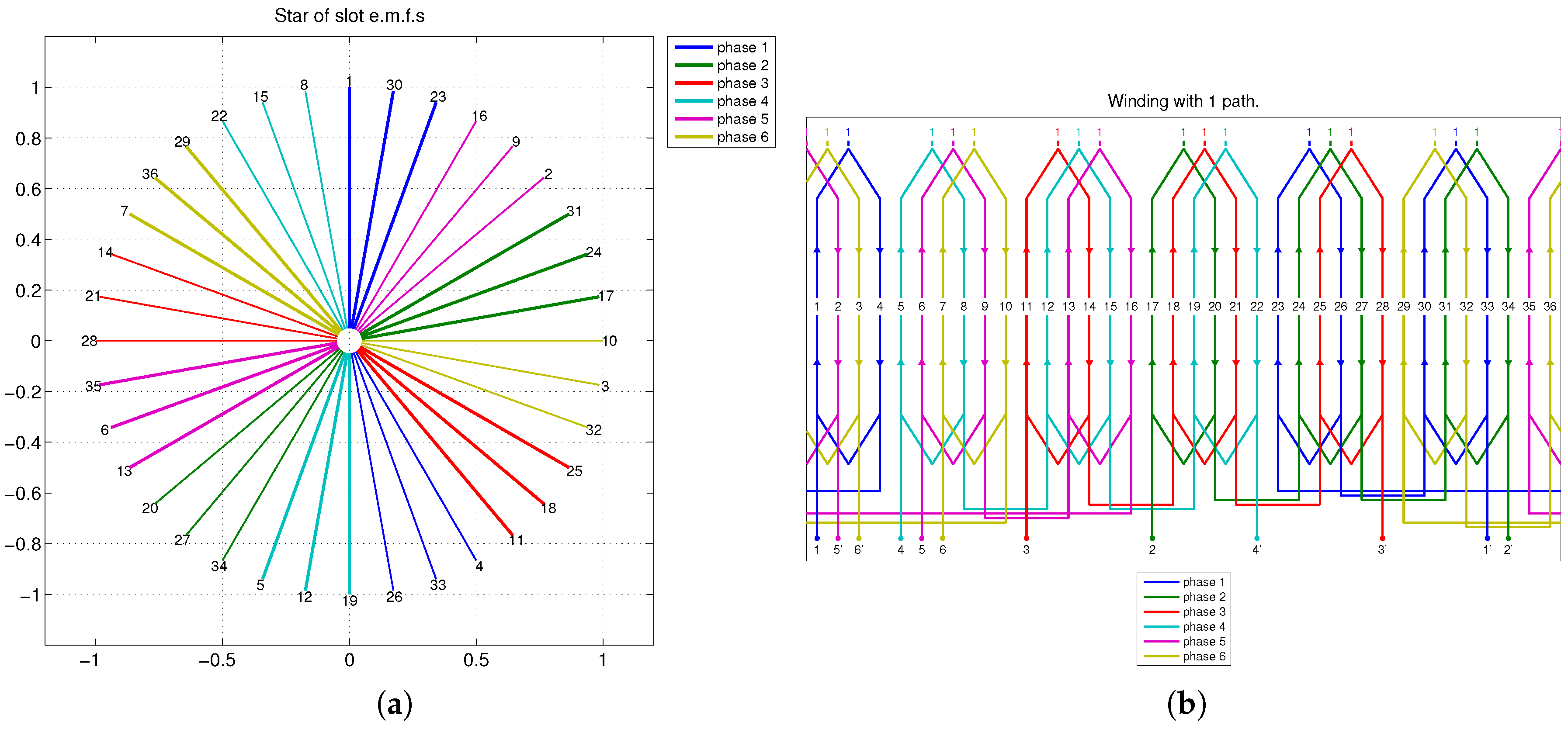
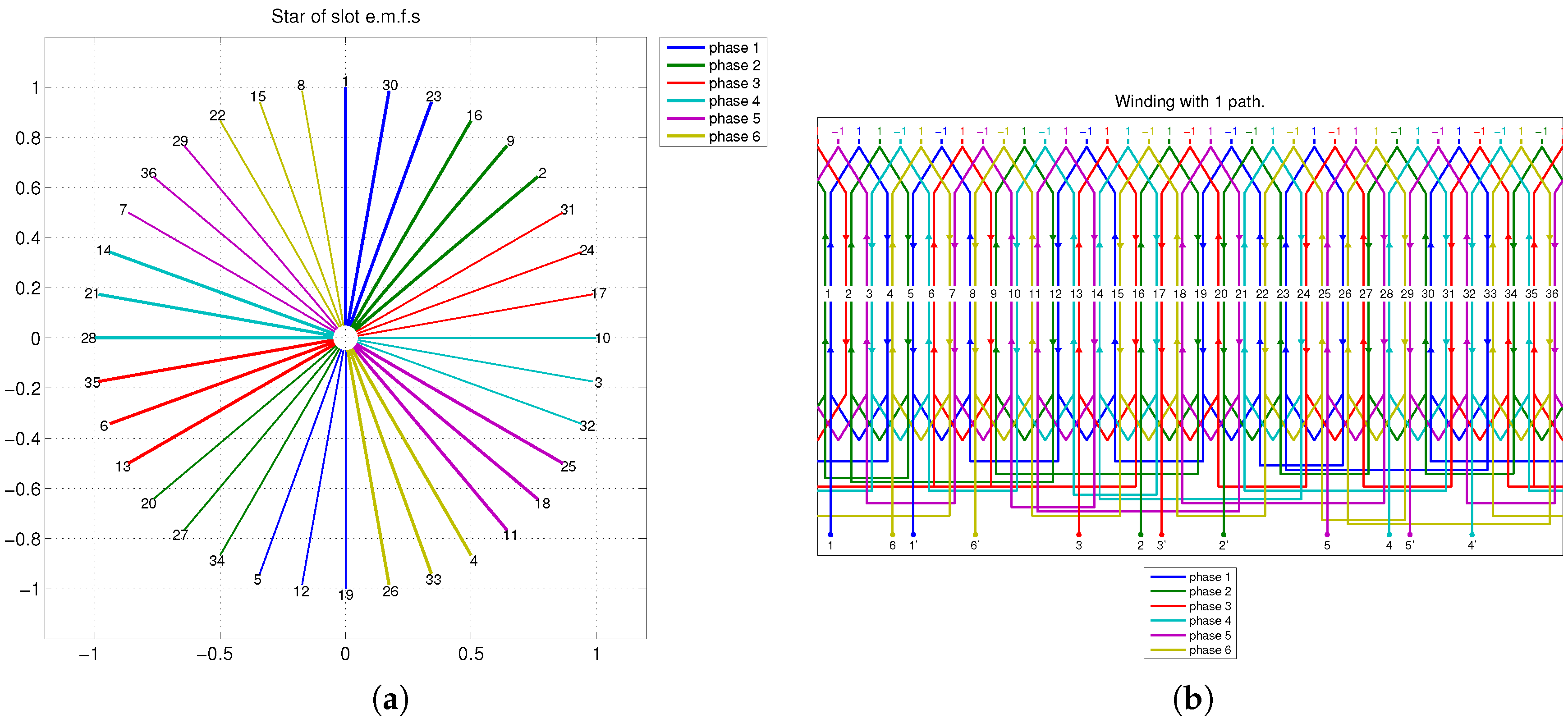
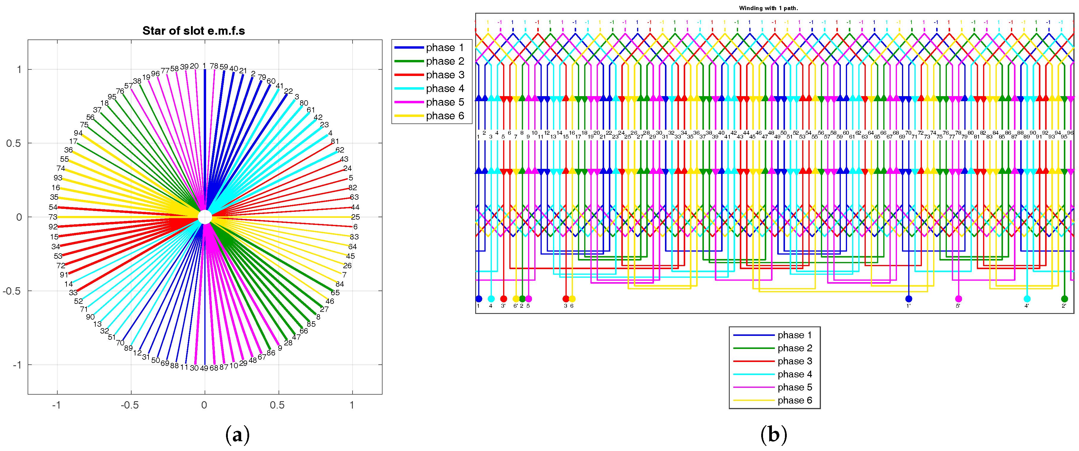
Figure 18.
(a) Star of slots of a 6-phase reduced single-layer winding with , and (b) related winding scheme with 1-st order double sided imbrication.
Figure 18.
(a) Star of slots of a 6-phase reduced single-layer winding with , and (b) related winding scheme with 1-st order double sided imbrication.
Table 1.
Order of the WDT elements.
Table 1.
Order of the WDT elements.
| | col. 1 | col. 2 | … | col. |
|---|
| row 1 | 1 | 2 | … | |
| row 2 | | | … | |
| row 3 | | | … | |
| ⋮ | ⋮ | ⋮ | ⋱ | ⋮ |
| row m | | | … | |
Table 2.
Winding Distribution Table for a winding with , and .
Table 2.
Winding Distribution Table for a winding with , and .
| 1 | 13 | 2 | 14 | 3 | 15 | 4 | 16 |
| 5 | 17 | 6 | 18 | 7 | 19 | 8 | 20 |
| 9 | 21 | 10 | 22 | 11 | 23 | 12 | 24 |
Table 3.
Electrical angles of the star of slots ().
Table 3.
Electrical angles of the star of slots ().
| 0° | | | ⋯ | |
|---|
| 1-st row | 1 | 2 | 3 | ⋯ | |
| ⋮ | ⋮ | ⋮ | ⋮ | ⋱ | ⋮ |
| t-th row | | | | ⋯ | N |
Table 4.
Electrical angles of the EMF star phasors for , and .
Table 4.
Electrical angles of the EMF star phasors for , and .
| Electr. Angles | 0° | 30° | 60° | 90° | 120° | 150° | 180° | 210° | 240° | 270° | 300° | 330° |
|---|
| Phasor pairs | 1 | 2 | 3 | 4 | 5 | 6 | 7 | 8 | 9 | 10 | 11 | 12 |
| 13 | 14 | 15 | 16 | 17 | 18 | 19 | 20 | 21 | 22 | 23 | 24 |
Table 5.
Winding Distribution Table with repetitions, for a winding with , and .
Table 5.
Winding Distribution Table with repetitions, for a winding with , and .
| 1 | 2 | 3 | 4 | | 13 | 14 | 15 | 16 |
| 5 | 6 | 7 | 8 | + | 17 | 18 | 19 | 20 |
| 9 | 10 | 11 | 12 | | 21 | 22 | 23 | 24 |
Table 6.
Reordering of the rows of a WDT for an m-phase reduced system winging with .
Table 6.
Reordering of the rows of a WDT for an m-phase reduced system winging with .
| Phases | col. 1 | col. 1 | … | col. | | Phases | col. 1 | col. 1 | … | col. |
|---|
| 1 | … | … | … | … | | 1 | … | … | … | … |
| ⋮ | ⋮ | ⋮ | ⋱ | … | | | … | … | … | … |
| | | | | | | 2 | … | … | … | … |
| … | … | … | … | | | … | … | … | … |
| … | … | … | … | | ⋮ | ⋮ | ⋮ | ⋱ | … |
| ⋮ | ⋮ | ⋮ | ⋱ | … | | | … | … | … | … |
| m | … | … | … | … | | m | … | … | … | … |
Table 7.
WDT for a single-layer, three-phase coil winding with , and .
Table 7.
WDT for a single-layer, three-phase coil winding with , and .
Table 8.
WDT for a single-layer, three-phase bar winding with , and .
Table 8.
WDT for a single-layer, three-phase bar winding with , and .
| 1 | 10 | 19 | 2 | 11 | −20 | −3 | −12 | −21 | |
| 4 | 13 | 22 | 5 | 14 | −23 | −6 | −15 | −24 |
| 7 | 16 | 25 | 8 | 17 | −26 | −9 | −18 | −27 |
Table 9.
WDT for a double-layer, three-phase winding with , and .
Table 9.
WDT for a double-layer, three-phase winding with , and .
| 1 | 2 | −3 | + | 10 | 11 | −12 | + | 19 | 20 | −21 | = | 1 | 2 | 7 | 8 | 19 | 20 | −3 | −12 | −21 | |
| 4 | 5 | −6 | 13 | 14 | −15 | 22 | 23 | −24 | 4 | 5 | 13 | 14 | 22 | 23 | −6 | −15 | −24 |
| 7 | 8 | −9 | 16 | 17 | −18 | 25 | 26 | −27 | 7 | 8 | 16 | 17 | 25 | 26 | −9 | −18 | −27 |
Table 10.
WDT for a double-layer, three-phase winding with , and considering all coil sides.
Table 10.
WDT for a double-layer, three-phase winding with , and considering all coil sides.
| 1 | −5 | 2 | −6 | 7 | −11 | 8 | −12 | 19 | −25 | 20 | −24 | −6 | 10 | −15 | 19 | −24 | 1 |
| 4 | −8 | 5 | −9 | 13 | −17 | 14 | −18 | 22 | −26 | 23 | −27 | −9 | 13 | −18 | 22 | −27 | 4 |
| 7 | −11 | 8 | −12 | 16 | −20 | 17 | −21 | 25 | −2 | 26 | −3 | −3 | 7 | −12 | 16 | −21 | 25 |
Table 11.
WDT for a double-layer, three-phase concentrated winding with and .
Table 11.
WDT for a double-layer, three-phase concentrated winding with and .
| 1 | 8 | −6 | ⟹ | 1 | 8 | −9 | ⟹ | 8 | −9 | 1 | ⟹ | 8 | −9 | −9 | 1 | 1 | −2 |
| 4 | 2 | −9 | 4 | 2 | −3 | 2 | −3 | 4 | 2 | −3 | −3 | 4 | 4 | −5 |
| 7 | 5 | −3 | 7 | 5 | −6 | 5 | −6 | 7 | 5 | −6 | −6 | 7 | 7 | −8 |
Table 12.
Winding Distribution Table for a symmetrical non-reduced winding with , , and .
Table 12.
Winding Distribution Table for a symmetrical non-reduced winding with , , and .
| 1 | 30 | 23 | −16 | −9 | −2 | |
| 31 | 24 | 17 | −10 | −3 | −32 |
| 25 | 18 | 11 | −4 | −33 | −26 |
| 19 | 12 | 5 | −34 | −27 | −20 |
| 13 | 6 | 35 | −28 | −21 | −14 |
| 7 | 36 | 29 | −22 | −15 | −8 |
Table 13.
Winding Distribution Table for a symmetrical reduced winding with , , and .
Table 13.
Winding Distribution Table for a symmetrical reduced winding with , , and .
Table 14.
WDT for a single-layer, 2-phase winding with and , after swapping.
Table 14.
WDT for a single-layer, 2-phase winding with and , after swapping.
| 1 | 2 | 3 | 4 | 5 | 6 | 7 | −15 | −16 | −17 | −18 | −19 | −20 | −21 |
| 8 | 9 | 10 | 11 | 12 | 13 | 14 | −22 | −23 | −24 | −25 | −26 | −27 | −28 |
Table 15.
Winding Distribution Table for a double layer winding with , and .
Table 15.
Winding Distribution Table for a double layer winding with , and .
| 1 | 2 | −3 | + | 22 | 23 | −24 | = | 1 | 22 | 2 | 23 | −3 | −24 | |
| 4 | 5 | −6 | 25 | 26 | −27 | 4 | 25 | 5 | 26 | −6 | −27 |
| 7 | 8 | −9 | 28 | 29 | −30 | 7 | 28 | 8 | 29 | −9 | −30 |
| 10 | 11 | −12 | 31 | 32 | −33 | 10 | 31 | 11 | 32 | −12 | −33 |
| 13 | 14 | −15 | 34 | 35 | −36 | 13 | 34 | 14 | 35 | −15 | −36 |
| 16 | 17 | −18 | 37 | 38 | −39 | 16 | 37 | 17 | 38 | −18 | −39 |
| 19 | 20 | −21 | 40 | 41 | −42 | 19 | 40 | 20 | 41 | −21 | −42 |
Table 16.
Winding Distribution Table for a winding with , , and .
Table 16.
Winding Distribution Table for a winding with , , and .
| 1 | 30 | 59 | 16 | 45 | 2 | 31 | 60 | 17 | 46 | 3 | 32 | −37 | −66 | −23 | −52 | −9 | −38 | −67 | −24 | −53 | −10 | −39 | −68 |
| 49 | 6 | 35 | 64 | 21 | 50 | 7 | 36 | 65 | 22 | 51 | 8 | −13 | −42 | −71 | −28 | −57 | −14 | −43 | −72 | −29 | −58 | −15 | −44 |
| 25 | 54 | 11 | 40 | 69 | 26 | 55 | 12 | 41 | 70 | 27 | 56 | −61 | −18 | −47 | −4 | −33 | −62 | −19 | −48 | −5 | −34 | −63 | −20 |
Table 17.
Double chording with a 3-rd order single-sided imbrication for , , and .
Table 17.
Double chording with a 3-rd order single-sided imbrication for , , and .
| 1 | −54 | 59 | −40 | 45 | −26 | 31 | 60 | 17 | 46 | 3 | 32 | 61 | 18 | 47 | −52 | −9 | −38 | −67 | −24 | −53 | −10 | −39 | −68 |
| 49 | −30 | 35 | −16 | 21 | −2 | 7 | 36 | 65 | 22 | 51 | 8 | 37 | 66 | 23 | −28 | −57 | −14 | −43 | −72 | −29 | −58 | −15 | −44 |
| 25 | −6 | 11 | −64 | 69 | −50 | 55 | 12 | 41 | 71 | 27 | 56 | 13 | 42 | 71 | −4 | −33 | −62 | −19 | −48 | −5 | −34 | −63 | −20 |
| | ↑ | | ↑ | | ↑ | | | | | | | ↑ | ↑ | ↑ | | | | | | | | | |
Table 18.
Double chording with a 3-rd order double-sided imbrication for , , and .
Table 18.
Double chording with a 3-rd order double-sided imbrication for , , and .
| 1 | −54 | 59 | −40 | 45 | −26 | 31 | 60 | 17 | 46 | 3 | 32 | −37 | 18 | −23 | 4 | −9 | 62 | −67 | −24 | −53 | −10 | −39 | −68 |
| 49 | −30 | 35 | −16 | 21 | −2 | 7 | 36 | 65 | 22 | 51 | 8 | −13 | 66 | −71 | 52 | −57 | 38 | −43 | −72 | −29 | −58 | −15 | −44 |
| 25 | −6 | 11 | −64 | 69 | −50 | 55 | 12 | 41 | 71 | 27 | 56 | −61 | 42 | −47 | 28 | −33 | 14 | −19 | −48 | −5 | −34 | −63 | −20 |
| | ↑ | | ↑ | | ↑ | | | | | | | | ↑ | | ↑ | | ↑ | | | | | | |
Table 19.
Triple chording with a 3-rd order double-sided imbrication and zone widening by 2 coils for , , and .
Table 19.
Triple chording with a 3-rd order double-sided imbrication and zone widening by 2 coils for , , and .
| 1 | −54 | 59 | −40 | 45 | −26 | 31 | 60 | 17 | 46 | 3 | 32 | 61 | 18 | −23 | 4 | −9 | 62 | −67 | 48 | −53 | −10 | −39 | −68 |
| 49 | −30 | 35 | −16 | 21 | −2 | 7 | 36 | 65 | 22 | 51 | 8 | 37 | 66 | −71 | 52 | −57 | 38 | −43 | 24 | −29 | −58 | −15 | −44 |
| 25 | −6 | 11 | −64 | 69 | −50 | 55 | 12 | 41 | 71 | 27 | 56 | 13 | 42 | −47 | 28 | −33 | 14 | −19 | 72 | −5 | −34 | −63 | −20 |
| | ↑ | | ↑ | | ↑ | | | | | | | | | | ↑ | | ↑ | | ↑ | | | | |
Table 20.
Winding factor harmonics with different optimization techniques for , , and .
Table 20.
Winding factor harmonics with different optimization techniques for , , and .
| | Normal Chording | Double Chording | Triple Chording |
|---|
| Harm. Order | WDT () | Chording () | 1-Sided Imbric. | 2-Sided Imbric. | 2-Sided Imbric. + Zone Widen. |
|---|
| 1-st | 0.955 | 0.923 | 0.902 | 0.881 | 0.878 |
| 3-rd | 0.633 | 0.451 | 0.365 | 0.277 | 0.268 |
| 5-th | 0.201 | 0.154 | 0.026 | 0.002 | 0.002 |
| 7-th | 0.132 | 0.036 | 0.008 | 0.020 | 0.017 |
| 9-th | 0.201 | 0.154 | 0.013 | 0.154 | 0.109 |
| 11-th | 0.080 | 0.087 | 0.078 | 0.072 | 0.055 |
Table 21.
WDT with a double chording and a 3-rd order double-sided imbrication for , , and .
Table 21.
WDT with a double chording and a 3-rd order double-sided imbrication for , , and .
| 1 | 2 | 3 | 4 | 5 | 6 | 7 | 8 | 9 | 10 | −11 | −12 | −13 | −14 | −15 | −16 | −17 | −18 | −19 | −20 |
| 21 | 22 | 23 | 24 | 25 | 26 | 27 | 28 | 29 | 30 | −31 | −32 | −33 | −34 | −35 | −36 | −37 | −38 | −39 | −40 |
| 41 | 42 | 43 | 44 | 45 | 46 | 47 | 48 | 49 | 50 | −51 | −52 | −53 | −54 | −55 | −56 | −57 | −58 | −59 | −60 |
Table 22.
WDT with a double chording and a 3-rd order double-sided imbrication for , , and .
Table 22.
WDT with a double chording and a 3-rd order double-sided imbrication for , , and .
Table 23.
Winding factor harmonics with different optimization techniques for , and .
Table 23.
Winding factor harmonics with different optimization techniques for , and .
| Harmonic Order | WDT () | Chording () | Single-Sided Imbrication | Double-Sided Imbrication |
|---|
| 1-st | 0.827 | 0.787 | 0.778 | 0.761 |
| 3-rd | 0 | 0 | 0 | 0 |
| 5-th | 0.167 | 0 | 0 | 0 |
| 7-th | 0.121 | 0.071 | 0.035 | 0.20 |
| 9-th | 0 | 0 | 0 | 0 |
| 11-th | 0.080 | 0.076 | 0.014 | 0.087 |
Table 24.
WDT of a 6-phase reduced winding with , , .
Table 24.
WDT of a 6-phase reduced winding with , , .
| 1 | 30 | 59 | 16 | 45 | 2 | 31 | 60 | 17 | 46 | 3 | 32 |
| 61 | 18 | 47 | 4 | 33 | 62 | 19 | 48 | 5 | 34 | 63 | 20 |
| 49 | 6 | 35 | 64 | 21 | 50 | 7 | 36 | 65 | 22 | 51 | 8 |
| 37 | 66 | 23 | 52 | 9 | 38 | 67 | 24 | 53 | 10 | 39 | 68 |
| 25 | 54 | 11 | 40 | 69 | 26 | 55 | 12 | 41 | 70 | 27 | 56 |
| 13 | 42 | 71 | 28 | 57 | 14 | 43 | 72 | 29 | 58 | 15 | 44 |
Table 25.
WDT of a 6-phase reduced winding with , , , after swapping.
Table 25.
WDT of a 6-phase reduced winding with , , , after swapping.
| 1 | 30 | 59 | 16 | 45 | 2 | −37 | −66 | −23 | −52 | −9 | −38 |
| 31 | 60 | 17 | 46 | 3 | 32 | −67 | −24 | −53 | −10 | −39 | −68 |
| 61 | 18 | 47 | 4 | 33 | 62 | −25 | −54 | −11 | −40 | −69 | −26 |
| 19 | 48 | 5 | 34 | 63 | 20 | −55 | −12 | −41 | −70 | −27 | −56 |
| 49 | 6 | 35 | 64 | 21 | 50 | −13 | −42 | −71 | −28 | −57 | −14 |
| 7 | 36 | 65 | 22 | 51 | 8 | −43 | −72 | −29 | −58 | −15 | −44 |
| | ↑ | | | | | | ↑ | | | | |
Table 26.
WDT of a 6-phase reduced winding with , , , and double sided imbrication of the 1-st order.
Table 26.
WDT of a 6-phase reduced winding with , , , and double sided imbrication of the 1-st order.

 ,
, 


