Article

A Unidirectional DC-DC Autotransformer for DC Grid Application

1
State Key Laboratory of Advanced Electromagnetic Engineering and Technology, Huazhong University of Science and Technology, Wuhan 430074, China
2
TBEA China Xinjiang Sunoasis Co., Ltd., Xi’an 710000, China
*
Author to whom correspondence should be addressed.
Energies 2018, 11(3), 530; https://doi.org/10.3390/en11030530
Submission received: 28 January 2018 / Revised: 9 February 2018 / Accepted: 23 February 2018 / Published: 1 March 2018
(This article belongs to the Section F: Electrical Engineering)

Abstract

:
Conventional unidirectional DC-DC converters for DC grid application employ DC-AC-DC two-stage conversion technology and suffer from high converter cost and power loss. To solve these issues, a unidirectional step-up DC-DC autotransformer (UUDAT) and a unidirectional step-down DC-DC autotransformer (DUDAT) are studied. The UUDAT and DUDAT are composed of a series connection of diode bridges and voltage source converters. Topologies of UUDAT and DUDAT are detailed. The harmonic and un-controllability issues are discussed. Control and possible application scenarios for UUDAT and DUDAT are depicted. DC fault isolation mechanism and the methods of dimensioning the voltage and power ratings of the components in UUDAT and DUDAT are studied. Extensive simulations on power system level and experiments on a UUDAT and DUDAT prototype verified their technical feasibility.

1. Introduction

With the increased penetration of renewable power generation and the development of technologies such as modular multilevel converters (MMC), high-power DC circuit breakers, DC-DC converters, DC-DC autotransformers, DC power flow controllers, and DC energy dissipation devices, there has been significant interest in developing DC grids in the power industry in recent years.
A DC grid requires interconnection of multiple DC transmission lines at the DC terminals. To interconnect DC transmission lines with different voltage levels, DC-DC converters will be used. A number of DC-DC topologies have been proposed in the literature, such as the front-to-front type DC-DC [1,2], the multiple dual active bridge DC-DC [3], the multilevel modular DC-DC [4,5,6,7], the LCL DC-DC [8,9], the DC-DC autotransformer (DC AUTO) [10,11,12,13,14,15], and the hybrid cascaded transformer-less DC-DC [16], the high step-up ratio softswitching DC-DC converter [17], the medium-voltage high-power DC-DC converter for DC distribution systems [18], and the multifunctional full-bridge DC-DC LLC resonant converter building block [19].
Among these high-voltage/high-power topologies for power system level application, the DC AUTO and the hybrid cascaded transformer-less DC-DC are the most efficient solutions for multi-terminal HVDC networks [20]. The hybrid cascaded DC-DC converter requires a series connection of hundreds of Insulated Gate Bipolar Transistors (IGBTs) in its direct switch, which may limit its application.
Most of the above DC-DC converters are bidirectional, meaning that DC power can flow bi-directionally between the two DC systems. At certain application fields such as wind power collection by the DC grid [21,22,23,24,25,26], the power only needs to flow in a single direction. The DC-DC converters could be further optimized to reduce the converter cost in those application fields.
Conventional high-voltage/high-power unidirectional DC-DC converters at HVDC level employs DC-AC-DC technology with a VSC and an un-controlled rectifier connected in a front-to-front mode [1,21,22,23,24]. The transferred DC power is firstly inverted from DC to AC by the VSC and then rectified from AC to DC by the uncontrolled rectifier. All the transferred DC power needs two-stage AC-DC converting, which results in high converter rating and high operating power loss. Reference [3] compares the cost and performance of the multilevel modular DC converter [4] and the modular DC-DC converter constructed by multiple dual-active bridge units (DAB) [27]. Results show that the modular DC-DC converter based on DAB employs a lower number of semiconductors than the multilevel modular DC converter of [4]. From the perspective of a power converter, the DAB requires a full DC-AC-DC converting for the transferred DC power.
A step-up unidirectional DC AUTO (UUDAT) was briefly introduced in [15] and investigated in [28]. The UUDAT can reduce converter rating and operating power loss. This paper further expands the work of [15,28]. A unidirectional step-down DC AUTO (DUDAT) will be proposed. Pros and cons of the UUDAT and DUDAT will be analyzed in more detail. Possible applications of the unidirectional DC AUTOs will be discussed. Experimental results of a unidirectional DC AUTO prototype will also be presented, which are contributions that have not been reported in any reference of [14,15,28] that studied DC AUTO technology.

2. Step-Up and Step-Down Unidirectional DC AUTO

2.1. Conventional Unidirectional DC-AC-DC

Figure 1a shows the circuit diagram of a conventional unidirectional DC-AC-DC. It is mainly composed of an MMC and an uncontrolled diode rectifier (DIO). The DC power can only flow in a single direction from one DC system E1 to the other DC system E2. The transferred DC power will be firstly inverted by the MMC and then rectified by the DIO. The power ratings of MMC, DIO and AC link are the same as the rated DC power. Therefore, the cost and operating loss of the DC-AC-DC technology shown in Figure 1a is high.

2.2. Topologies of Unidirectional DC AUTO

To reduce the converter rating and the operating power loss, Figure 1b,c show the topologies of UUDAT and DUDAT. The UUDAT is composed of a series connection of two DIO (DIO1, DIO3) and one MMC (MMC2). The DUDAT is composed of a series connection of two MMC (MMC1, 3) and one DIO (composed of DIO2P and DIO2N). In Figure 1b, MMC is represented by a half-bridge sub-module.
The UUDAT is used to transfer DC power from the low voltage DC system E1 to the high voltage DC system E2. According to the power flow analyzing method of [15], part of the DC power is transferred through the direct electrical connection formed by E1 and idc2, and the other part is firstly inverted by MMC2 and then rectified by DIO1, 3.
The DUDAT is used to transfer DC power from E2 to E1. Similar to the UUDAT, part of the DC power is transferred through the direct electrical connection formed by E1 and idc2 and the other part is firstly inverted by MMC1, 3 and then rectified by DIO2P and DIO2N. 12-pulses diode bridges are used at each DIO1–DIO3 to reduce the harmonic content.

3. Control and Possible Application of the Unidirectional DC AUTO

3.1. Control of UUDAT and DUDAT

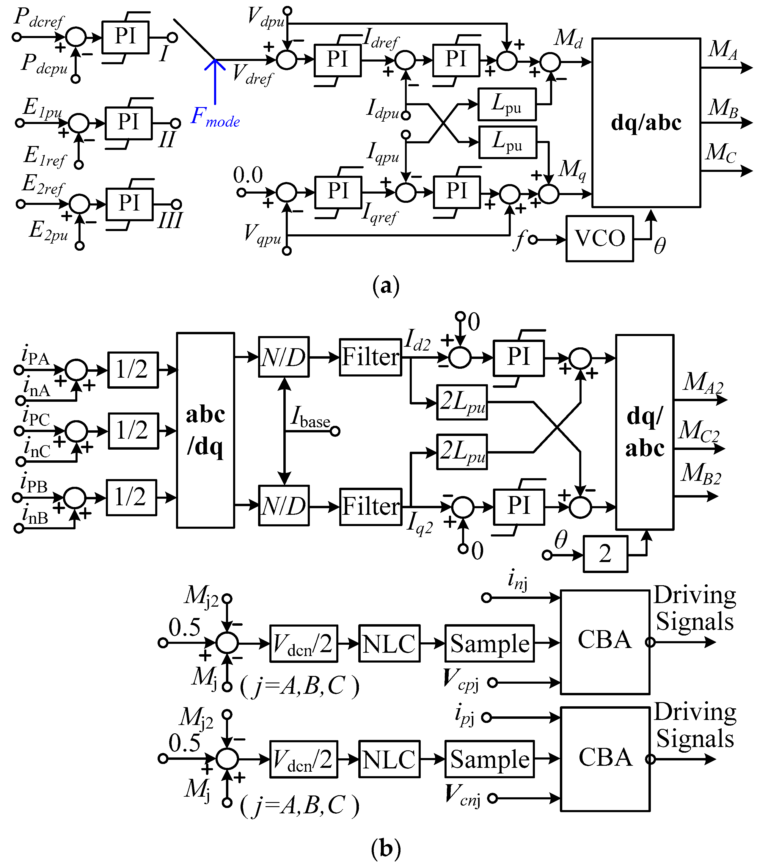
For the UUDAT, by increasing the AC voltage of MMC2, the voltage rectified by DIO1, 3 can be increased. Thus, E2 will be increased, which increases idc2. Therefore, the DC power can be controlled by controlling the AC voltage in the UUDAT. Figure 2 shows the upper layer control of UUDAT. The controller is composed of an outer loop DC power-DC voltage control, a middle loop AC voltage control and an inner loop AC current control. Outputs of the upper layer control are the modulation indices in abc frame, and a VCO (voltage-controlled oscillator) is used to provide reference angle for abc/dq transformation.
The UUDAT has three control modes, either to control its transferred DC power (mode I), control the DC voltage at the lower DC voltage side (mode II) or control the DC voltage at the higher DC voltage side (mode III). For mode II, by reducing the output AC voltage of MMC2, the DC power absorbed by UUDAT can be reduced and therefore E1 can be increased. Analysis of mode III is similar and will not be duplicated.
In Figure 2a, Pdcpu is the per unit value of the DC power. The positive DC current directions are shown in Figure 1b,c. Vdpu and Vqpu are the dq component of the common bus AC voltage in a rotating dq frame. Vdref is the reference value of Vdpu. Idpu and Iqpu are the dq components of AC current iAiC. Lpu is the per unit value of reactance from inner electromotive force (EMF) point of an MMC to the common AC bus. Md and Mq are the dq modulation indices. The subscript pu of Figure 2a stands for per unit value taking the rated value of each variable as the base value; the subscript ref stands for reference value.
The upper layer control of the DUDAT is similar to the UUDAT and will not be duplicated.
Figure 2b shows the lower level control of MMC, which is composed of a circulating current suppressing control and a capacitor voltage balancing algorithm (CBA). The nearest level control modulation (NLC) and CBA based on soring with reduced switching frequency [29] are employed. The output of NLC is sampled at the 5 kHz frequency.

3.2. Operation of UUDAT and DUDAT Interfaced to Passive Components at Load Side

The DC voltages at the lower and higher voltage sides are important for successful operation of UUDAT and DUDAT. When the load side of UUDAT is connected to passive components, E2 will be clamped at E1 if MMC2 is not in operation. After enabling the mode III control of Figure 2a, E2 can be controlled to its reference value. Therefore, the DC voltage at the load side of UUDAT can only vary from E1 to rated value. The DC voltage at the load side of conventional unidirectional DC-AC-DC could vary from 0 to the rated value if the load side is connected to passive components. Since the UUDAT is dedicated to HVDC application, the operating scenario of interfacing the load side to passive components is very rare.
If the load side of DUDAT is connected to passive components, the DUDAT could not be started without over-dimensioning the voltage ratings of MMC1, 3 as during starting, all of the higher voltage side DC voltage is applied to the series connection of MMC1, 3. Since such an operating scenario is most likely to be unrealistic, the incapability of such an operating mode will not hamper the application of DUDAT.

3.3. Possible Application Scenario of UUDAT

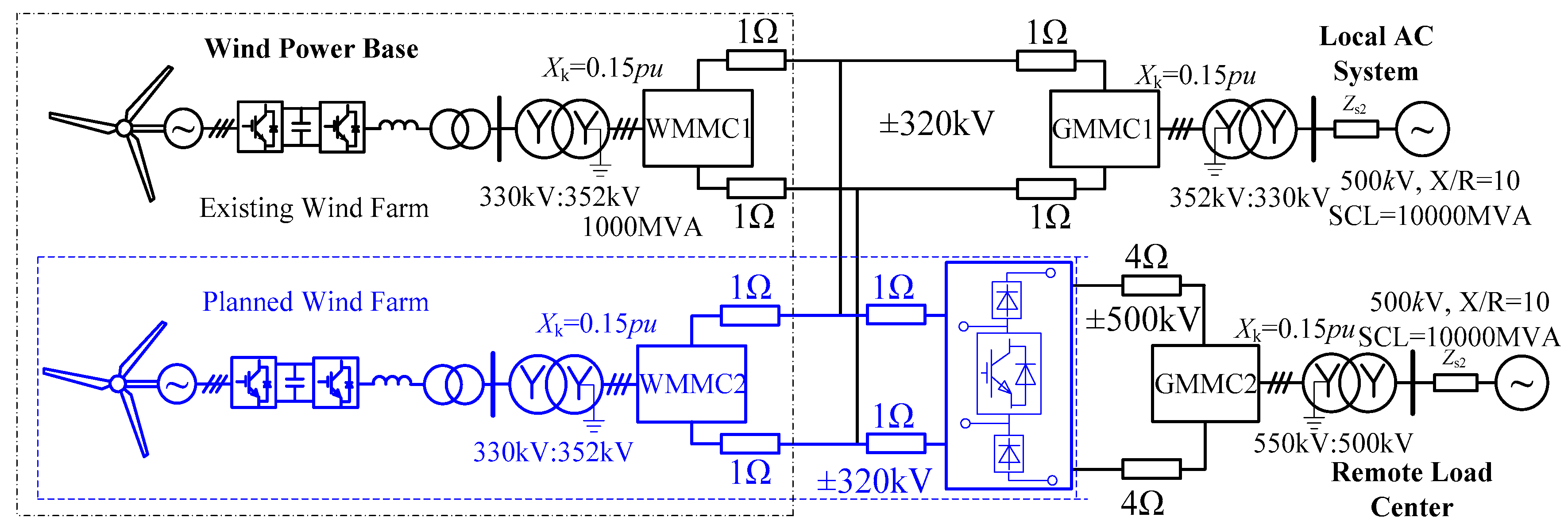
Figure 3 illustrates the possible application of UUDAT. It is used to transfer wind power from a low voltage DC system to a high voltage DC system. The parts inside the blue dash box belong to planned systems and the other parts belong to an existing system. The existing system includes a local ±320 kV lower voltage HVDC link that transfer wind power to a Local AC System and a ±500 kV HVDC passes through the region. The ±500 kV DC system supplies power to a Remote Load Center from a remote power center and has no electrical connection with the local region.
At a certain stage, the Wind Power Base plans a new wind farm. Since the Wind Power Base is remote from the Remote Load Center and the Local AC System is a weak AC system, HVDC will still be used to transfer the power of the planned wind farm. The voltage level of the new HVDC link needs to be determined. Since the Local AC System is not able to consume the total wind power from the existing wind farm and the planned wind farm, a new ±320 kV that only transfers power from the planned wind farm to the existing Local AC System will not be considered.
If a ±500 kV MMC is built and assumes that there is a long distance between the existing wind farm and planned wind farm, then the existing wind farm is not able to transfer DC power to the remote load center. An alternative scheme is to build a ±320 kV MMC and a ±320 kV/±500 kV UUDAT, as shown in the dashed box of Figure 3. Such scheme has the benefit that:
  • Add the output power of the existing wind farm and planned wind farm to smooth the total output wind power and therefore reduce the impact of wind power oscillations on power system;
  • Enable more flexible power transmission, the power from both the existing wind farm and the planned wind farm could be transferred to either the Local AC System or to the Remote Load Center.
The system of Figure 3 could well represent some of the key issues related to large-scale wind power grid integration in China [30]. There is a large amount of wind power base in the west and north regions of China. In addition, each wind power base is composed of several wind farms scattered among a wide area. There are also several existing UHVDC links that are in the same region as these wind power bases. Majority of the wind power generated by these wind power bases are currently consumed by local AC network which is weak AC system, as the load centers are located in the east coast and south region of China. The system of Figure 3 provides a reference to the practical issue of integrating large-scale wind power in China.

4. DC Fault Isolation Mechanism of Unidirectional DC AUTO

4.1. Response to E1 Fault and E2 Fault of UUDAT

For the UUDAT shown in Figure 1b, under pole-to-pole DC fault at E2, the lower voltage system E1 provides DC fault current through DIO1, 3. DC circuit breakers [31] CBP and CBN are connected in series with DIO1, 3 to isolate DC fault at E2.
Under pole to pole DC fault at E1, the DC voltage of E2 is applied to the series connection of DIO1, 3. If the total DC voltage rating of DIO1, 3 is lower than E2, additional diodes are needed to increase the reverse withstanding voltage of DIO1, 3. System response to pole-to-ground DC fault of UUDAT is similar to pole-to-pole DC fault and will not be replicated.

4.2. Dimensioning of the Diode Bridges in UUDAT

Denote the rated DC voltage of DIO1 as Vdc1n, the rated RMS (root mean square) line-line voltage at the converter bridge of each 6-pulse diode bridge of DIO1 is [32].
V line rms = π V dc 1 n / 3 2 N dio
where Ndio is the number of 6-pulse diode bridges. Ndio = 2 for Figure 1b. The peak voltage applied at each D1–D6 of Figure 1b is the peak line-line voltage, which is expressed as
V dio = 2 V line rms = π V dc 1 n / 3 N dio
Neglecting the voltage drops across the DC transmission lines and denoting k as the stepping ratio (E2 = kE1). Thus, Vdc1n = (k − 1)E1/2, Equation (2) is further written as,
V dio = π ( E 2 E 1 ) / 6 N dio = ( k 1 ) π E 1 / 6 N dio
Equation (3) is the rated voltage of each D1–D6 without considering the DC fault isolating capability.
During DC fault at E1, the voltage applied at each D1–D6 is
V dio E 1 flt = E 2 / 4 N dio = k E 1 / 4 N dio
Comparing (3) and (4), to inherently isolate the E1 fault by blocking MMC2, the condition of V dio V dio E 1 flt needs to be met. The condition is further expressed as,
k 2 π / ( 2 π 3 ) 1.91
If (5) is not met, the voltage rating of each D1–D6 needs to be dimensioned according to (4). From (3)–(5), rated voltage of each D1–D6 should be dimensioned as,
V dio = { ( k 1 ) π E 1 / 6 N dio , k 2 π / ( 2 π 3 ) k E 1 / 4 N dio , k < 2 π / ( 2 π 3 )
Total power rating of DIO1, 3 is, therefore,
P dio = 2 N dio V dio I dio = 2 N dio V dio P N / E 2
Substituting (6) into (7) results,
P dio = { P N / 2 , k < 2 π / ( 2 π 3 ) π P N ( 1 1 / k ) / 3 , k 2 π / ( 2 π 3 )

4.3. Dimensioning of DCCB in UUDAT

The hybrid DCCB reported in [31] will be used in the UUDAT. During E2 fault, the DC voltage applied at each CBP and CBN is E1/2 and the DC current flowing through CBP and CBN equals the fault current provided by E1. Therefore, the rated DC voltage and DC current of each DCCB are respectively E1/2 and PN/E1. According to [33], cost of bidirectional DCCB is 30% the cost of an MMC with the same voltage and current rating. Cost of a DCCB is viewed as converter rating in this paper. Only unidirectional DCCB needs to be used in UUDAT, therefore, converter rating of two DCCB is
P dccb = 0.15 P N
According to [15], power rating of MMC2 in a UUDAT (also equals the total power rating of MMC1, 3 in a DUDAT) without considering DC fault isolating capability is
P MMC 2 UUDAT = ( P MMC 1 DUDAT + P MMC 3 DUDAT ) = P N ( 1 1 / k )
Summing up (9) and (10), the total MMC rating of UUDAT with bidirectional DC fault isolating capability is
P MMC UUDAT = ( 1.15 1 / k ) P N
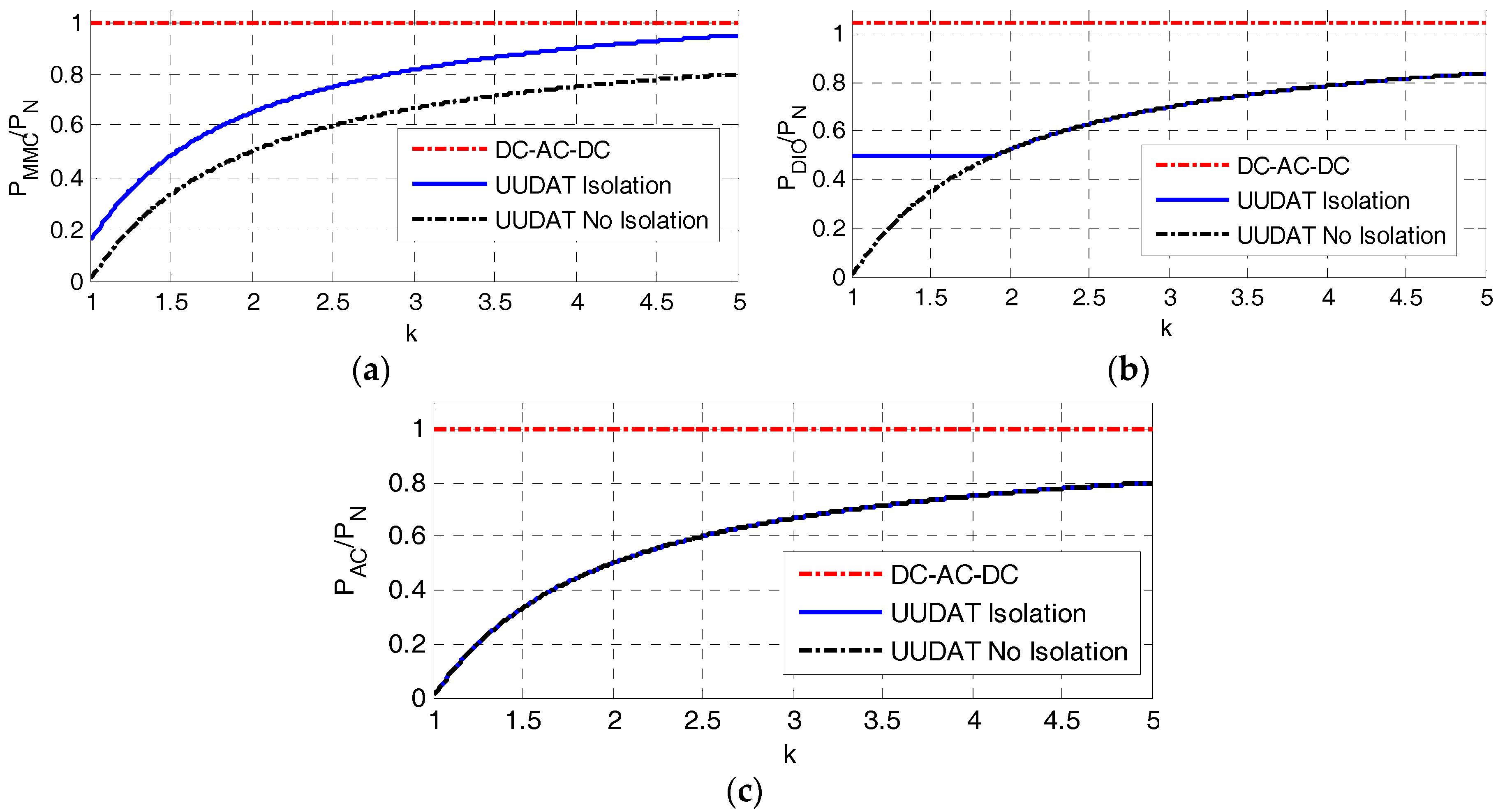
Figure 4a–c shows the power rating of MMC, diode bridges and AC link in a UUDAT versus the DC voltage stepping ratio. ‘DC-AC-DC’ represents conventional unidirectional DC-AC-DC, ‘UUDAT Isolation’ and ‘UUDAT No Isolation’ represent a UUDAT with and without bidirectional DC fault isolating capability.
Similar to the attribute of the bidirectional DC AUTO, Figure 4 shows the UUDAT can significantly save cost compared with DC-AC-DC technology under low and medium DC voltage stepping ratio (k ≤ 5).

4.4. DC Fault Isolating Mechanism of DUDAT

DC fault isolation of a DUDAT is exactly the same as DC fault isolation of a DC AUTO employing MMC converters [15]. The conclusions from [15] are summarized below without detailed analysis.
To isolate DC fault at E2, parts of the sub-modules of each arm of MMC1, 3 need to be replaced by sub-modules that can isolate DC fault current, such as the self-blocking sub-module (SBSM) used in [15]. To isolate DC fault at E1, the reverse withstanding voltage of each arm of MMC1, 3 should be E2/4. If k < 2, additional half bridge submodules (HBSM) should be added to each arm of MMC1, 3 to increase the reverse withstanding voltage of MMC1, 3.
In the case of k ≥ 2, DC fault at E1 can be isolated by tripping all the IGBTs of MMC1, 3. To isolate DC fault at E2, the additional converter rating because of replacing part of the HBSM with SBSM is,
P add , SBSM = c P N ( 1 1 / k ) E 1 / 2 ( E 2 E 1 )
Derivation of (12) can be referred to [15] where c = 0.5. the total MMC power rating in DUDAT is
P MMC k 2 = P N ( 1 1 k + c 2 k ) , k 2
In the case of k < 2, additional HBSMs need to be added to each arm of MMC1, 3 to increase the reverse withstanding voltages of MMC1, 3 during E1 fault. Power rating of the total HBSMs at MMC1, 3 becomes
P HBSM k < 2 = E 2 ( P VSC 1 + P VSC 3 ) / 2 ( E 2 E 1 ) , k 2
To isolate DC fault at higher voltage DC side, part of HBSMs of (14) need to be replaced by SBSM according to (12). Adding up (12) and (14) results,
P MMC k < 2 = P N ( 1 2 + c 2 k ) , k < 2
Organizing (13) and (15) in a single equation results
P MMC = { P N ( 1 2 + c 2 k ) , k < 2 P N ( 1 1 k + c 2 k ) , k 2
The DIO2 in a DUDAT does not affect the DC fault isolating capability of a DUDAT. Similar to Equation (10), power rating of DIO2 in DUDAT is
P dio = P N ( 1 1 / k )
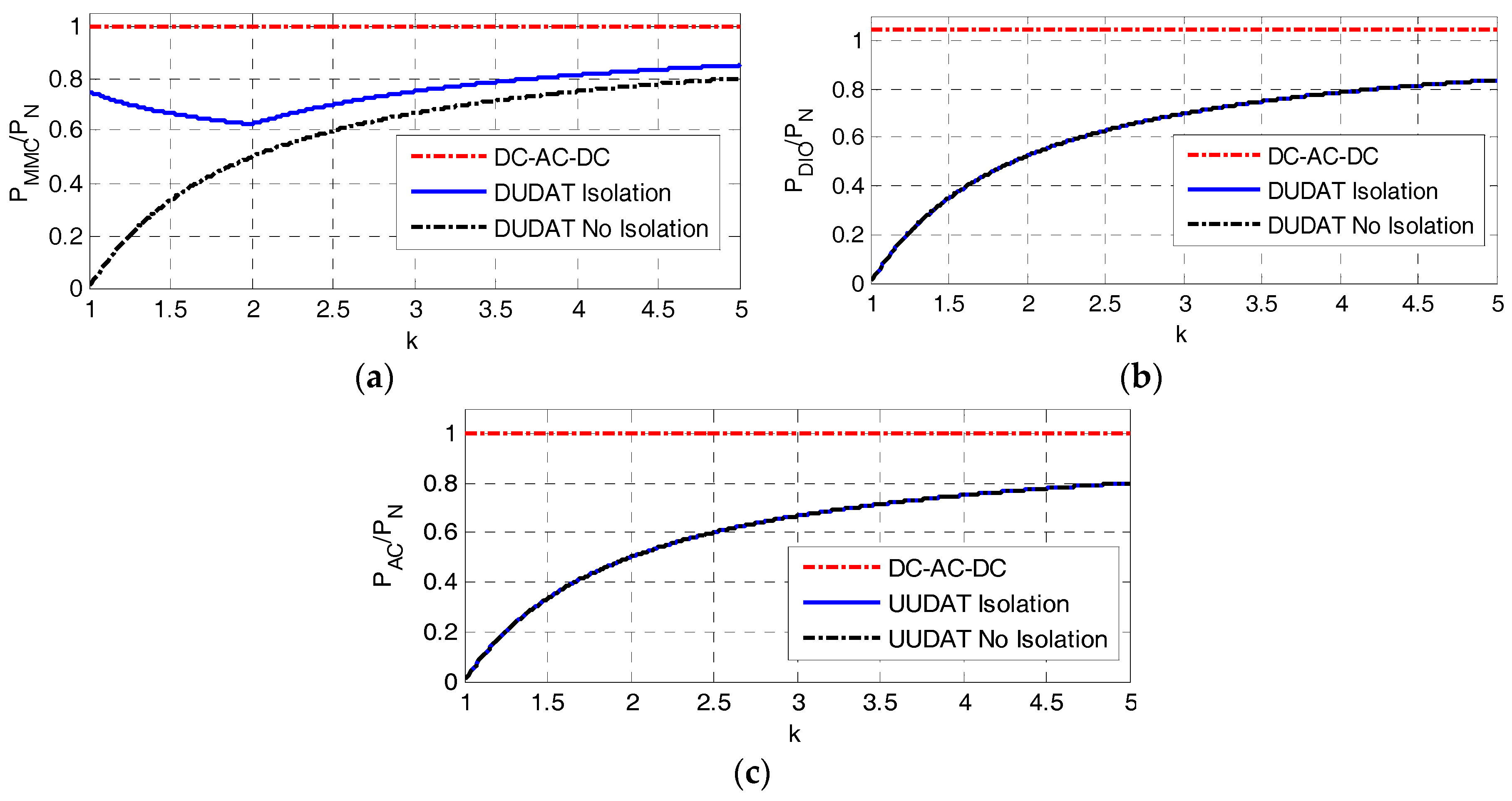
Figure 5 shows the total power rating of MMC1, 3 versus the DC voltage stepping ratio. At k = 2, PMMC reaches minimum value of 0.625PN. With k decreasing to be lower than 2, although PMMC1 and PMMC3 of (10) reduce, additional HBSMs are required to isolate E1 fault which increases MMC power rating according to (14). With k increasing to be higher than 2, the PMMC1 and PMMC3 of (10) play the dominant role in increasing PMMC of (16).
Figure 5a shows that under low and medium stepping ratio, power rating of MMC in a DUDAT with bidirectional DC fault isolating capability is about 60–80% of the MMC rating in conventional unidirectional DC-AC-DC. Figure 5b shows that power rating of the un-controlled rectifier in a DUDAT is significantly lower than in a DC-AC-DC. The power rating of the AC link in a DUDAT is the same as Figure 4c.

5. Simulation Verifications

5.1. Topologies of the Simulated Systems

To verify the control performance of unidirectional DC AUTOs, the systems shown in Figure 3 and Figure 6 are simulated in PSCAD/EMTDC. Parameters of UUDAT and DUDAT are listed in Table 1, Table 2, Table 3, Table 4 and Table 5.
Figure 6 is used to test the control of DUDAT. The parts inside the red box represents the DUDAT. Lower voltage side and higher voltage side of the DUDAT are, respectively, connected to a ±320 kV and ±500 kV MMC. All the three control modes of Figure 2a will be tested.

5.2. Parameters of the Simulated Unidirectional DC AUTOs

The UUDAT and DUDAT with topologies shown in Figure 1 are simulated. The rated values of E1 and E2 are, respectively, ±320 kV and ±500 kV. The rated DC power is 1000 MW.
Table 1 shows the power ratings and voltage ratings of the MMC and diode bridges in the test UUDAT. Without considering DC fault isolating capability, the rated DC voltage of diode valve of DIO1, 3 is 188.5 kV (total voltage rating of the two D1 of DIO1). To protect DIO1, 3 from over-voltage during E1 fault, voltage rating of the diode valve of DIO1, 3 is increased up to 250 kV. Power rating of the AC transformer connected to DIO1, 3 is 180 MVA.
Table 2 lists the voltage and current ratings of the DCCB, CBP and CBN, in the UUDAT.
Table 3 lists the voltage and power ratings of MMC1, 3 in the DUDAT.
Table 4 lists the parameters of MMC1, 3 of DUDAT and MMC2 of UUDAT. The MMCs are modelled following the detailed equivalent modelling approaches of [34] where dynamics of each sub-module capacitor is represented. The DIO1–DIO3 are modelled with each diode valve representing by a single diode. The smoothing reactor Ldc1 is set to be 0.1 H.
Table 5 lists the parameters of transformers in the simulated UUDAT and DUDAT. Winding configurations of these transformers are shown in Figure 1b,c. The primary windings are connected to the AC terminals of MMC, the secondary and tertiary windings are connected to diode bridges.

5.3. Simulations of Integrating Wind Power Using UUDAT

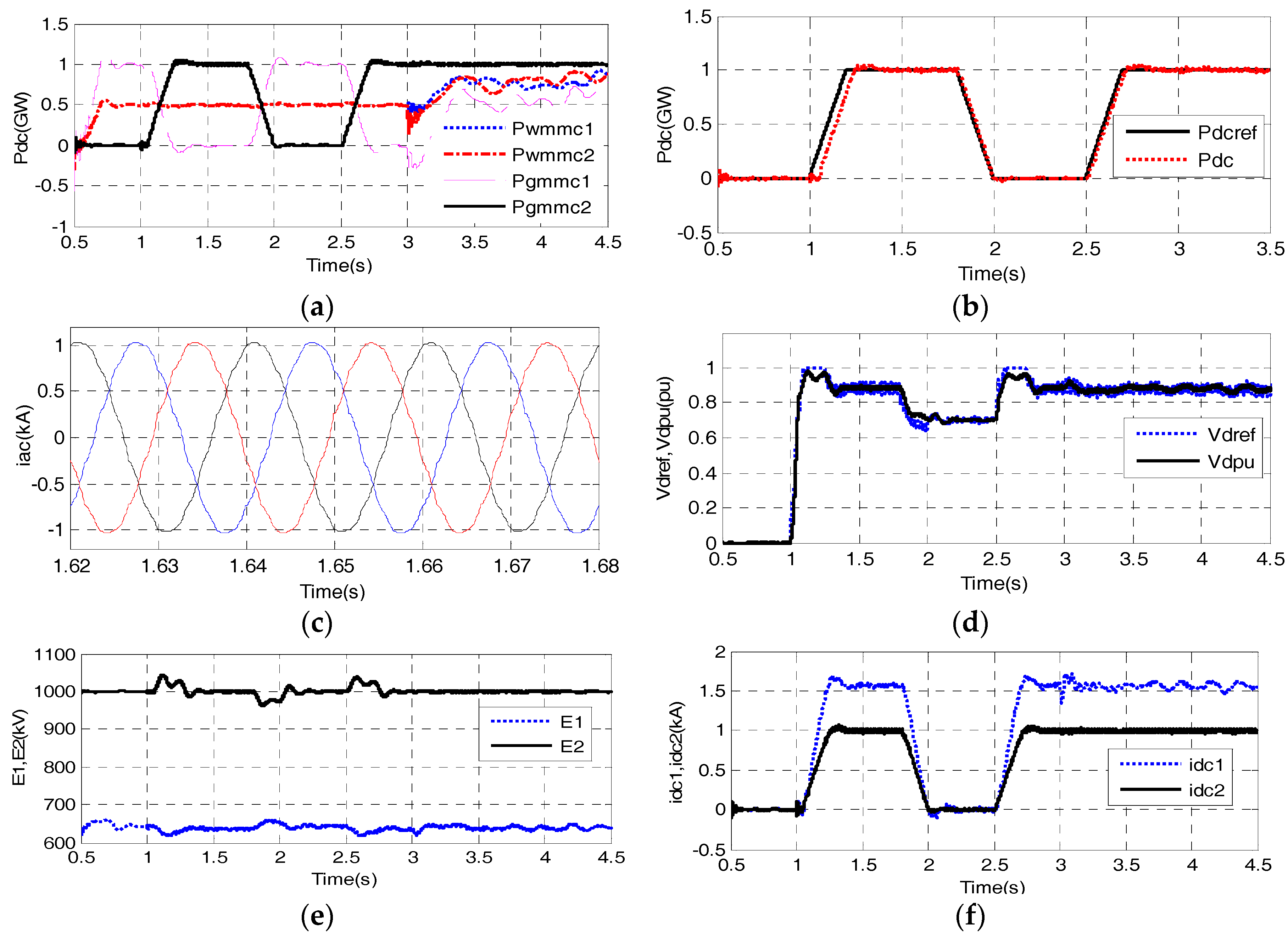
Figure 7 shows simulation results of integrating wind power through UUDAT. The system of Figure 3 is simulated. GMMC1 and GMMC2 are, respectively, configured to control their DC terminal voltages. WMMC1 and WMMC2 are configured to control the AC voltage of each wind farm. The UUDAT is configured to control its transferred DC power (Mode I of Figure 2a).
The power reference of UUDAT is stepped from 0 to 1.0 GW at 1.0 s, decreased from 1 GW to 0 at 1.8 s, and further stepped from 0 to 1.0 GW at 2.5 s. A rate limit of ±5 GW/s is applied at changing of the power reference. Power of the two wind farms are the same and stay at 500 MW before 3.0 s. Wind power oscillations are applied from 3.0 s.
Figure 7a shows that Pgmmc2 changes with the change of the power reference of UUDAT. GMMC1 acts as the balancing terminal of the system. After applying wind power oscillations, the Pgmmc2 still stays un-changed and GMMC1 balances all the wind power oscillations.
Figure 7b shows the power reference of UUDAT and the DC power measured at higher voltage side of UUDAT. It is seen that the DC power closely tracks the power reference.
Figure 7c shows that because of the 12-pulse diode bridge, harmonics are observed at the AC current of MMC2 at full DC power.
Figure 7d shows the reference value and measured value of the d-channel AC voltage at the common AC bus. It is seen that Vdpu is increased to increase the transferred DC power and Vdpu is decreased to decrease the transferred DC power.
Figure 7e shows the DC voltages at higher voltage side and lower voltage side of the UUDAT. Figure 7b,e show that even with non-ideal DC voltage source at the power side of UUDAT, the transferred DC power can still be controlled to its reference value.
Figure 7f shows the DC currents of UUDAT. Certain steady state harmonics are observed at the DC currents, which are similar to conventional LCC and can be attenuated by DC smoothing reactors. idc1 starts to oscillate after applying the wind power oscillations at 3.0 s and the magnitude of idc2 stays almost un-changed.

5.4. Simulations on the Control of DUDAT

Figure 8 shows simulation results of the test system composed of DUDAT. As shown in Figure 6 GMMC1 and GMMC2 are initially configured to control their respective DC terminal voltages. All the three control modes of Figure 2a are tested. The applied disturbances are as follows:
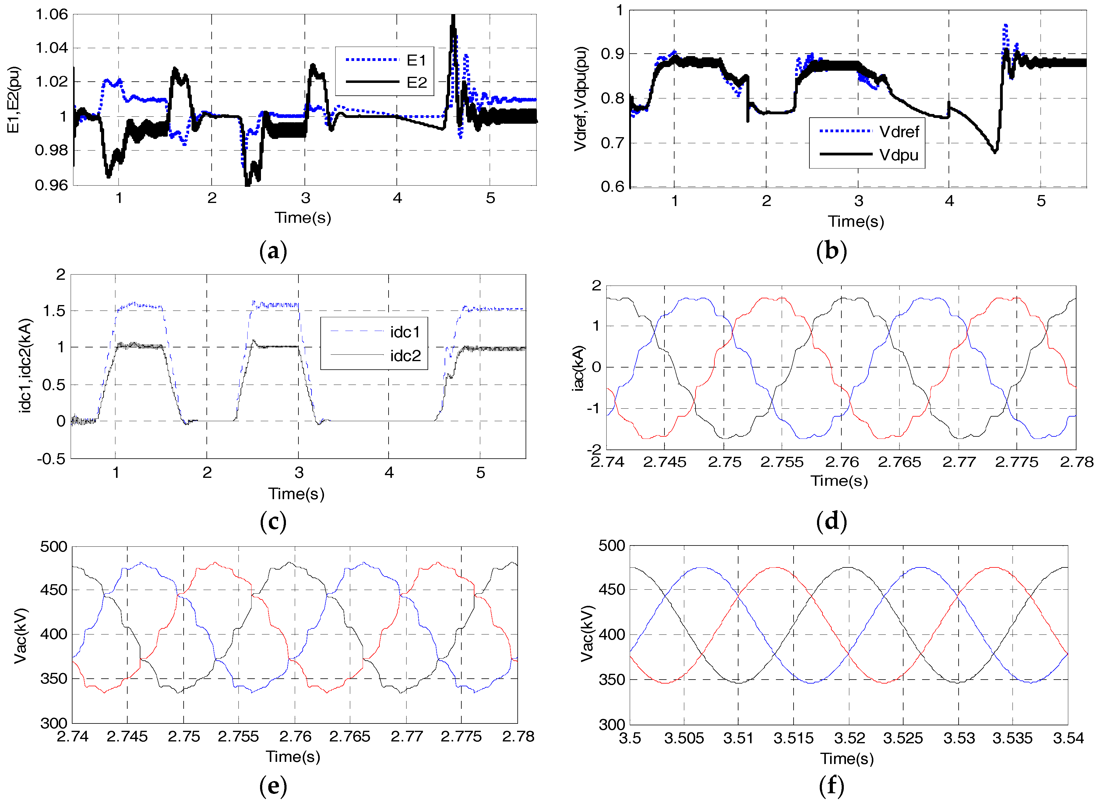
0.7–1.0 s: DC power reference of DUDAT increased from 0 to 1.0 pu. 1.5–1.7 s: DC power reference of DUDAT decreased from 1.0 pu to 0. 1.8 s: UUDAT configured to control E1, GMMC1 configured to control DC power. 2.3–2.5 s: Absorbed DC power of GMMC1 increased from 0 to 1 pu. 3.0–3.2 s: Absorbed DC power of GMMC1 decreased from 1 pu to 0. 4.0 s: UUDAT configured to control E2, GMMC2 configured to control DC power. 4.5–4.8 s: Injected DC power of GMMC2 increased from 0 to 1.0 pu.
Figure 8a shows the DC voltages are well controlled to their respective value except some transients during applying of the disturbances. There is only a maximum of 6% over-shoot which is acceptable.
Figure 8b shows the d-channel AC voltage in per unit form. The AC voltage generally follows its reference value in steady state except there will be mismatch during the instant of applying disturbance.
Figure 8c shows the DC currents. It is seen that despite harmonics at the inner AC circuit of the DUDAT, harmonics at the DC currents stay at relatively low value.
Figure 8d shows the output AC current of DUDAT under full DC power condition.
Figure 8e,f, respectively, show the phase-ground voltage at the converter bridge of MMC1 under full DC power and zero DC power. As the inner AC circuit of the DUDAT and also UUDAT is an independent AC system, harmonics could be allowed in the inner AC system and the harmonics at the DC side can be reduced by smoothing reactors.

6. Prototype Experimental Verifications

6.1. The Scaled-Down Experimental Set Up

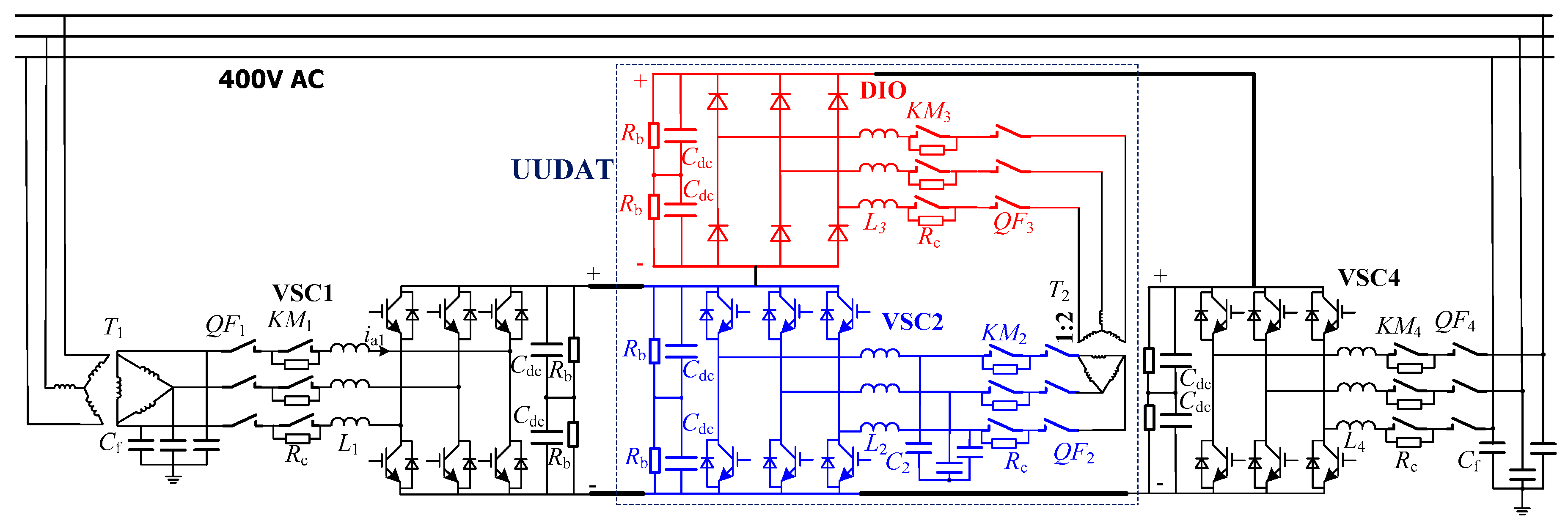
Figure 9 shows the schematic of the experimental set-up of UUDAT. VSC1 and VSC4 are, respectively, used to provide a 375 V and a 750 V DC voltage. The series connection of VSC2 and DIO forms a UUDAT. Rated DC voltage and DC power of VSC2 and DIO are the same and are, respectively, 375 V and 25 kW. The rated DC voltage and DC power of VSC1 and VSC4 are 750 V and 50 kW. Parameters of the passive components of the test rig are listed in Table 6.
Figure 10 shows the schematic of the experimental set-up of UUDAT. Figure 11 is derived from Figure 10 by reversing the positions of VSC2 and DIO.

6.2. Experimental Results

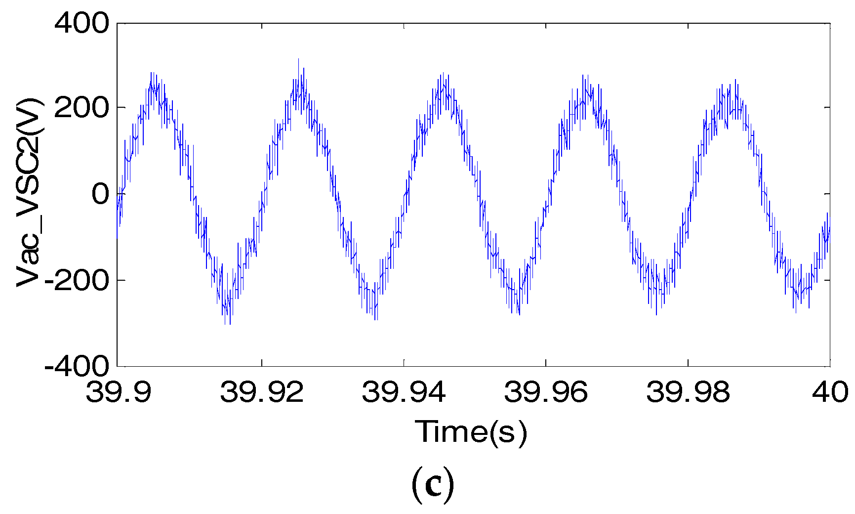
Figure 12 shows the experimental results of UUDAT. DC voltages of VSC1 and VSC4 are controlled to be around 375 V and 750 V, as shown in Figure 12a. Figure 12b shows the DC power of VSC1 and VSC2. Power transferring from the DC side to the AC side is defined as the positive power direction. Figure 12b shows DC power of VSC2 is 50% the DC power of VSC1, which verifies the operating principle of DC AUTO. Figure 12c shows the line-line AC voltage at the converter side of VSC2. Sinusoidal waveform of AC voltage is achieved. Because of using 2-level VSC and 6-pulse Diode Bridge, harmonics are observed in the experiments.
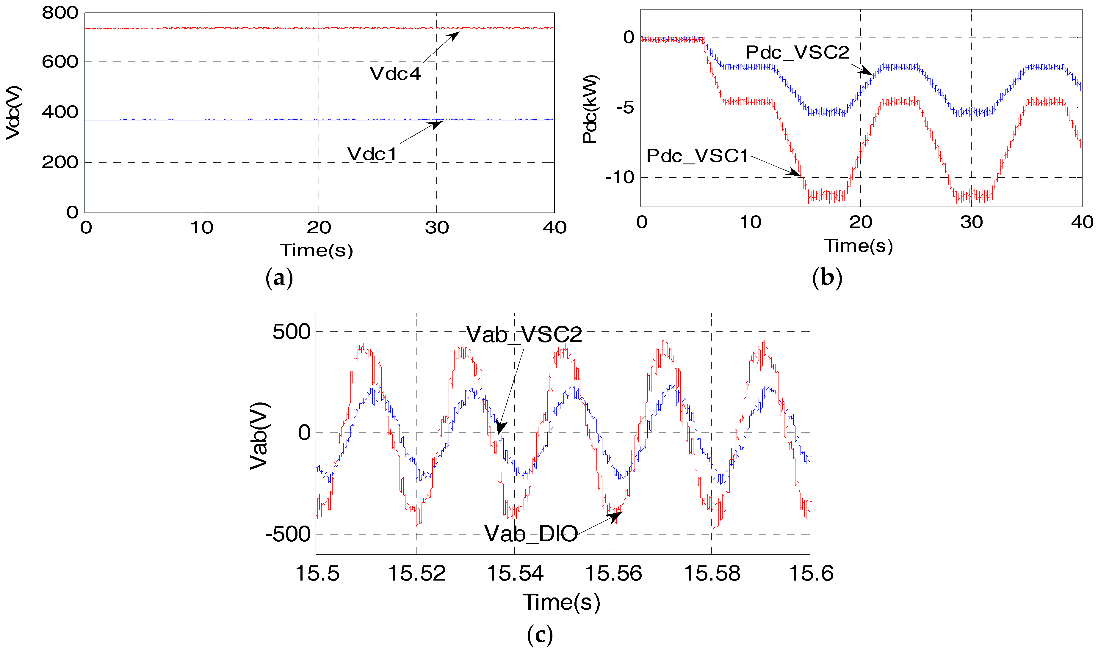
Figure 13 shows the experimental results of DUDAT. Figure 13a shows that DC voltages of VSC1 and VSC4 are controlled to be 375 V and 750 V. Figure 13b shows the DC power of VSC2 and VSC1. As expected, the DC power of VSC2 is about 50% the DC power of VSC1, which verifies the operating principle of DC AUTO. Figure 13c shows the line-line AC voltages at the AC side of VSC2 and the diode bridge. Because of using a Y/Δ AC transformer with turn ratio of 2:1, there are phase difference and magnitude difference at the two AC voltages.

7. Conclusions

The UUDAT and DUDAT are composed of a series connection of diode bridges and MMCs and are a further optimization of DC AUTO for application where only single power flow direction is required. The UUDAT and DUDAT have lower converter rating and operating power loss compared with the bidirectional DC AUTO and the unidirectional DC-AC-DC. Upper layer controller for UUDAT and DUDAT is composed of an outer power or DC voltage loop, a middle AC voltage loop and an inner AC current loop. The control enables a UUDAT or a DUDAT to successfully control either its transferred DC power or DC terminal voltages. Possible application scenarios of using UUDAT to transfer surplus wind power from a lower voltage DC system to a higher voltage DC system is proposed. Extensive simulations verified the feasibility of using UUDAT to transfer wind power, using UUDAT to power resistive load and the different control modes of DUDAT. Technical feasibility of UUDAT and DUDAT are further verified by experiments on a 375 V/750 V, 10 kW prototype of unidirectional DC AUTOs.

Acknowledgments

This work was supported by the State Grid Corporation of China Science and Technology Project (NYN17201600314) and the Initiative Postdocs Supporting Program (No. BX201700088).

Author Contributions

All authors contributed to this work by collaboration. Meng Zhou and Wenping Zuo performed the modeling and experiment; Meng Zhou wrote the paper; This work was carried out under the advisement of and with regular feedback from Wang Xiang and Weixing Lin. Jinyu Wen provided several very useful suggestions to improve the paper quality. All authors revised and approved the publication of the paper.

Conflicts of Interest

The authors declare no conflict of interest.

References

  1. Luth, T.; Merlin, M.M.C.; Green, T.C.; Hassan, F.; Barker, C.D. High-frequency operation of a DC/AC/DC system for HVDC applications. IEEE Trans. Power Electron. 2014, 29, 4107–4115. [Google Scholar]
  2. Jovcic, D.; Zhang, H. Dual Channel Control with DC Fault Ride through for MMC-Based, Isolated DC/DC Converter. IEEE Trans. Power Deliv. 2017, 32, 1574–1582. [Google Scholar] [CrossRef]
  3. Engel, S.P.; Stieneker, M.; Soltau, N.; Rabiee, S.; Stagge, H.; de Doncker, R.W. Comparison of the modular multilevel DC converter and the dual-active bridge converter for power conversion in HVDC and MVDC grids. IEEE Trans. Power Electron. 2015, 30, 124–137. [Google Scholar] [CrossRef]
  4. Ferreira, J.A. The multilevel modular DC converter. IEEE Trans. Power Electron. 2013, 28, 4460–4465. [Google Scholar] [CrossRef]
  5. Filsoof, K.; Lehn, P.W. A Bidirectional Modular Multilevel DC–DC Converter of Triangular Structure. IEEE Trans. Power Electron. 2015, 30, 54–64. [Google Scholar] [CrossRef]
  6. Xiang, X.; Zhang, X.; Luth, T.; Merlin, M.M.C.; Green, T. A Compact Modular Multilevel DC-DC Converter for High Step-ratio MV and HV Use. IEEE Trans. Ind. Electron. 2018. [Google Scholar] [CrossRef]
  7. Ren, Q.; Sun, C.; Xiao, F. A Modular Multilevel DC–DC Converter Topology with a Wide Range of Output Voltage. IEEE Trans. Power Electron. 2017, 32, 6018–6030. [Google Scholar] [CrossRef]
  8. Jovcic, D.; Zhang, L. LCL DC/DC Converter for DC Grids. IEEE Trans. Power Deliv. 2013, 28, 2071–2079. [Google Scholar] [CrossRef]
  9. Jovcic, D. Step-up DC–DC converter for megawatt size applications. IET Power Electron. 2009, 2, 675. [Google Scholar] [CrossRef]
  10. Schӧn, A.; Bakran, M.M. A New HVDC-DC Converter for the Efficient Connection of HVDC Networks; PCIM Europe: Nurnberg, Germany, 2013. [Google Scholar]
  11. Schӧn, A.; Bakran, M. High power HVDC-DC converters for the interconnection of HVDC lines with different line topologies. In Proceedings of the IEEE ECCE-Asia ICPE Conference, Hiroshima, Japan, 18–21 May 2014; pp. 3255–3262. [Google Scholar]
  12. Schӧn, A.; Bakran, M. A new HVDC-DC converter with inherent fault clearing capability. In Proceedings of the 2013 15th European Conference on Power Electronics and Applications (EPE), Lille, France, 2–6 September 2013; pp. 1–10. [Google Scholar]
  13. Schӧn, A.; Bakran, M. Average loss calculation and efficiency of the new HVDC auto transformer. In Proceedings of the 2014 16th European Conference on Power Electronics and Applications (EPE’14-ECCE Europe), Lappeenranta, Finland, 26–28 August 2014; pp. 1–10. [Google Scholar]
  14. Lin, W.; Wen, J.; Cheng, S. Multiport DC-DC autotransformer for interconnecting multiple high-voltage DC systems at low cost. IEEE Trans. Power Electron. 2015, 30, 6648–6660. [Google Scholar] [CrossRef]
  15. Lin, W. DC-DC autotransformer with bidirectional DC fault isolating capability. IEEE Trans. Power Electron. 2015, 31, 5400–5410. [Google Scholar] [CrossRef]
  16. Yang, J.; He, Z.; Pang, H.; Tang, G. The hybrid-cascaded DC-DC converters suitable for HVDC applications. IEEE Trans. Power Electron. 2015, 30, 5358–5363. [Google Scholar] [CrossRef]
  17. Cui, S.; Soltau, N.; Doncker, R.W.D. A high step-up ratio soft switching dc-dc converter for interconnection of mvdc and HVDC grids. IEEE Trans. Power Electron. 2018, 33, 2986–3001. [Google Scholar] [CrossRef]
  18. Soltau, N.; Stagge, H.; Doncker, R.W.D.; Apeldoorn, O. Development and demonstration of a medium-voltage high-power dc-dc converter for DC distribution systems. In Proceedings of the IEEE 5th International Symposium on Power Electronics for Distributed Generation Systems (PEDG), Galway, Ireland, 24–27 June 2014; pp. 1–8. [Google Scholar]
  19. Cecati, C.; Khalid, H.A.; Tinari, M.; Adinolfi, G.; Graditi, G. Hybrid DC Nano Grid with Renewable Energy Sources and Modular DC/DC LLC Converter Building Block. IET Power Electron. 2017, 10, 536–544. [Google Scholar] [CrossRef]
  20. Adam, G.; Gowaid, I.; Finney, S.; Holliday, D.; Williams, B. Review of dc-dc converters for multi-terminal HVDC transmission networks. IET Power Electron. 2016, 9, 281–296. [Google Scholar] [CrossRef] [Green Version]
  21. Meyer, C.; Hoing, M.; Peterson, A. Control and design of DC grids for offshore wind farms. IEEE Trans. Power Deliv. 2007, 43, 1475–1482. [Google Scholar] [CrossRef]
  22. Deng, F.; Chen, Z. Design of protective inductors for HVDC transmission line with DC grid offshore wind farms. IEEE Trans. Power Deliv. 2013, 28, 75–83. [Google Scholar] [CrossRef]
  23. Deng, F.; Chen, Z. Operation and control of a DC-grid offshore wind farm under DC transmission system faults. IEEE Trans. Power Deliv. 2013, 28, 1356–1363. [Google Scholar] [CrossRef]
  24. Dincan, C.; Kjaer, P.; Chen, Y.H.; Nielsen, S.-M.; Bak, C.L. Selection of dc/dc converter for offshore wind farms with mvdc power collection. In Proceedings of the 19th European Conference on Power Electronics and Applications (EPE’17 ECCE EUROPE), Warsaw, Poland, 11–14 September 2017. [Google Scholar]
  25. Yao, W.; Jiang, L.; Wen, J.; Wu, Q.; Cheng, S. Wide-Area Damping Controller for Power System Interarea Oscillations: A Networked Predictive Control Approach. IEEE Trans. Control Syst. Technol. 2015, 23, 27–36. [Google Scholar] [CrossRef]
  26. Xiang, W.; Lin, W.; Xu, L.; Wen, J. Enhanced Independent Pole Control of Hybrid MMC-HVDC System. IEEE Trans. Power Deliv. 2017, PP, 1. [Google Scholar] [CrossRef]
  27. Rodriguez, A.; Vazquez, A.; Lamar, D.G.; Hernando, M.M.; Sebastian, J. Different purpose design strategies and techniques to improve the performance of a dual active bridge with phase-shift control. IEEE Trans. Power Electron. 2015, 30, 790–804. [Google Scholar] [CrossRef]
  28. Lin, W.; Wen, J.; Yao, L.; Yang, B. Step-up unidirectional DC-DC autotransformer for HVDC applications. In Proceedings of the 2016 IEEE 8th International Power Electronics and Motion Control Conference (IPEMC-ECCE Asia), Hefei, China, 22–26 May 2016; pp. 703–707. [Google Scholar]
  29. Tu, Q.; Xu, Z.; Xu, L. Reduced switching-frequency modulation and circulation current suppression for modular multilevel converters. IEEE Trans. Power Deliv. 2011, 26, 2009–2017. [Google Scholar]
  30. Qi, Q.; Zhang, C. Study of some key issues related to large-scale wind power grid integration in China. In Proceedings of the 2012 IEEE PES Asia-Pacific Power and Energy Engineering Conference (APPEEC), Shanghai, China, 27–29 March 2012; pp. 1–4. [Google Scholar]
  31. Häfner, J.; Jacobson, B. Proactive Hybrid HVDC Breakers—A key innovation for reliable HVDC grids. In Proceedings of the Integrating Supergrids and Microgrids International Symposium, Bologna, Italy, 13–15 September 2011. [Google Scholar]
  32. Kundur, P.; Balu, N.J.; Lauby, M.G. Power System Stability and Control; McGraw-Hill: New York, NY, USA, 1994; Volume 7. [Google Scholar]
  33. Taherbaneh, M.; Jovcic, D.; Taisne, J.P.; Nguefeu, S. DC fault performance and cost analysis of dc grids for connecting multiple offshore wind farms. In Proceedings of the 2013 IEEE Grenoble PowerTech (POWERTECH), Grenoble, France, 16–20 June 2013; pp. 1–6. [Google Scholar]
  34. Yu, F.; Lin, W.; Wang, X.; Xie, D. Fast voltage-balancing control and fast numerical simulation model for the modular multilevel converter. IEEE Trans. Power Deliv. 2015, 30, 220–228. [Google Scholar] [CrossRef]
Figure 1. Topologies of unidirectional DC-AC-DC and unidirectional DC AUTOs. (a) Topology of conventional unidirectional DC-AC-DC; (b) Topology of a UUDAT; (c) Topology of a DUDAT.
Energies 11 00530 g001
Figure 2. Control diagrams of UUDAT and DUDAT. (a) Upper level control of a UUDAT or DUDAT; (b) Lower level control of UUDAT and DUDAT.
Energies 11 00530 g002
Figure 3. Schematic of a system for integrating wind power through UUDAT.
Energies 11 00530 g003
Figure 4. Power rating of MMC, un-controlled rectifier and AC transformer in a UUDAT versus stepping ratio. (a) Power rating of MMC; (b) Power rating of uncontrolled rectifier; (c) Power rating of transformer.
Energies 11 00530 g004
Figure 5. Power rating of the MMC, DIO and AC transformer in a DUDAT versus stepping ratio. (a) Power rating of MMC; (b) Power rating of uncontrolled rectifier; (c) Power rating of transformer.
Energies 11 00530 g005
Figure 6. Test system with DUDAT interfacing two MMC converters.
Energies 11 00530 g006
Figure 7. Simulation of integrating wind power through UUDAT. (a) DC power of WMMC1, WMMC2, MMC1 and GMMC2; (b) DC power reference and DC power of UUDAT; (c) Output AC current of MMC2 at full DC power; (d) Output AC voltage of MMC2 at zero DC power; (e) DC voltages at higher voltage side and lower voltage side; (f) DC currents at higher voltage side and lower voltage side.
Energies 11 00530 g007
Figure 8. Simulation of operation of DUDAT under different control modes. (a) DC voltages at lower voltage side and higher voltage side of DUDAT; (b) Vdref and Vdpu; (c) DC currents of DUDAT; (d) Output AC current of MMC1 under full DC power; (e) Output phase ground voltage of MMC1 under full DC power; (f) Output phase ground voltage of MMC1 under zero DC power.
Energies 11 00530 g008
Figure 9. Photograph of the experimental set-up for UUDAT and DUDAT.
Energies 11 00530 g009
Figure 10. Schematic of the experimental set-up of UUDAT.
Energies 11 00530 g010
Figure 11. Schematic of the experimental set-up of DUDAT.
Energies 11 00530 g011
Figure 12. Experimental results of UUDAT. (a) DC voltages at DC terminals of VSC1 and VSC4; (b) DC power of VSC1 and diode bridge; (c) line-line AC voltage of VSC2.
Energies 11 00530 g012aEnergies 11 00530 g012b
Figure 13. Experimental results of DUDAT. (a) DC voltages at DC terminal of VSC1 and VSC4; (b) DC power of VSC1 and diode bridge; (c) line-line AC voltage of VSC2 and diode bridge.
Energies 11 00530 g013
Table 1. Power and voltage ratings of the MMC and diode in the UUDAT.
RatingsBasic CaseAdditional Rating to Protect over E1 FaultTotal Rating
VDIO1,3 (kV)188.561.5250
VMMC2 (kV)6400640
PMMC2 (MW)3600360
Table 2. Voltage and current ratings of the DCCB in the simulated UUDAT.
NameVCBP (VCBN)ICBP (ICBN)PCBP (PCBN)
Value320 kV1.5625 kA1000 MW
Table 3. Power and voltage ratings of MMC1, 3 in the simulated DUDAT.
RatingsBasic CaseAdditional Rating to Protect over E1 FaultAdditional Rating to Protect over E2 FaultTotal Rating
VMMC1,3180 kV70 kV160 kV (for SBSM)250 kV
PMMC1,3180 MW70 MW80 MW330 MW
Table 4. Parameters of the MMC1, 3 in the simulated DUDAT and MMC2 in the simulated UUDAT.
NameMMC2 (for UUDAT)MMC1, 3 (for DUDAT)
Arm inductor (H)0.1650.025
Submodule capacitance (μF)23445000
Rated submodule voltage (kV)3.22.25
Number of sub-modules per arm200112
Number of SBSM per arm072
Table 5. Parameters of the AC transformers.
NameUUDATDUDAT
number of transformers22
rated power per transformer (MW)180180
Winding configurationY/Y/ΔΔ/Y/Δ
rated line-line AC Voltages (kV)352/83/8390/140/140
Leakage reactance (pu)0.10.1
Table 6. Parameters of passive components of the test rig.
ParametersValueParametersValue
Cf2.2 μFRb80 kΩ
Rc10 Ω/100 WL20.52 mH
L1(L3)3 mHC247 μF
Cdc14.1 mFL43 mH