1. Introduction
With the increased penetration of renewable power generation and the development of technologies such as modular multilevel converters (MMC), high-power DC circuit breakers, DC-DC converters, DC-DC autotransformers, DC power flow controllers, and DC energy dissipation devices, there has been significant interest in developing DC grids in the power industry in recent years.
A DC grid requires interconnection of multiple DC transmission lines at the DC terminals. To interconnect DC transmission lines with different voltage levels, DC-DC converters will be used. A number of DC-DC topologies have been proposed in the literature, such as the front-to-front type DC-DC [
1,
2], the multiple dual active bridge DC-DC [
3], the multilevel modular DC-DC [
4,
5,
6,
7], the LCL DC-DC [
8,
9], the DC-DC autotransformer (DC AUTO) [
10,
11,
12,
13,
14,
15], and the hybrid cascaded transformer-less DC-DC [
16], the high step-up ratio softswitching DC-DC converter [
17], the medium-voltage high-power DC-DC converter for DC distribution systems [
18], and the multifunctional full-bridge DC-DC LLC resonant converter building block [
19].
Among these high-voltage/high-power topologies for power system level application, the DC AUTO and the hybrid cascaded transformer-less DC-DC are the most efficient solutions for multi-terminal HVDC networks [
20]. The hybrid cascaded DC-DC converter requires a series connection of hundreds of Insulated Gate Bipolar Transistors (IGBTs) in its direct switch, which may limit its application.
Most of the above DC-DC converters are bidirectional, meaning that DC power can flow bi-directionally between the two DC systems. At certain application fields such as wind power collection by the DC grid [
21,
22,
23,
24,
25,
26], the power only needs to flow in a single direction. The DC-DC converters could be further optimized to reduce the converter cost in those application fields.
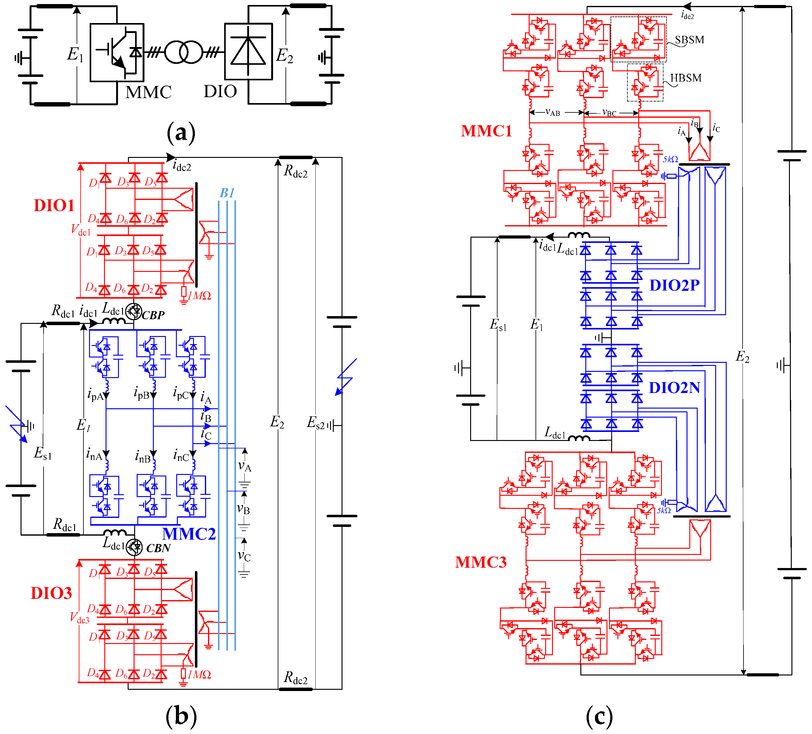
Conventional high-voltage/high-power unidirectional DC-DC converters at HVDC level employs DC-AC-DC technology with a VSC and an un-controlled rectifier connected in a front-to-front mode [
1,
21,
22,
23,
24]. The transferred DC power is firstly inverted from DC to AC by the VSC and then rectified from AC to DC by the uncontrolled rectifier. All the transferred DC power needs two-stage AC-DC converting, which results in high converter rating and high operating power loss. Reference [
3] compares the cost and performance of the multilevel modular DC converter [
4] and the modular DC-DC converter constructed by multiple dual-active bridge units (DAB) [
27]. Results show that the modular DC-DC converter based on DAB employs a lower number of semiconductors than the multilevel modular DC converter of [
4]. From the perspective of a power converter, the DAB requires a full DC-AC-DC converting for the transferred DC power.
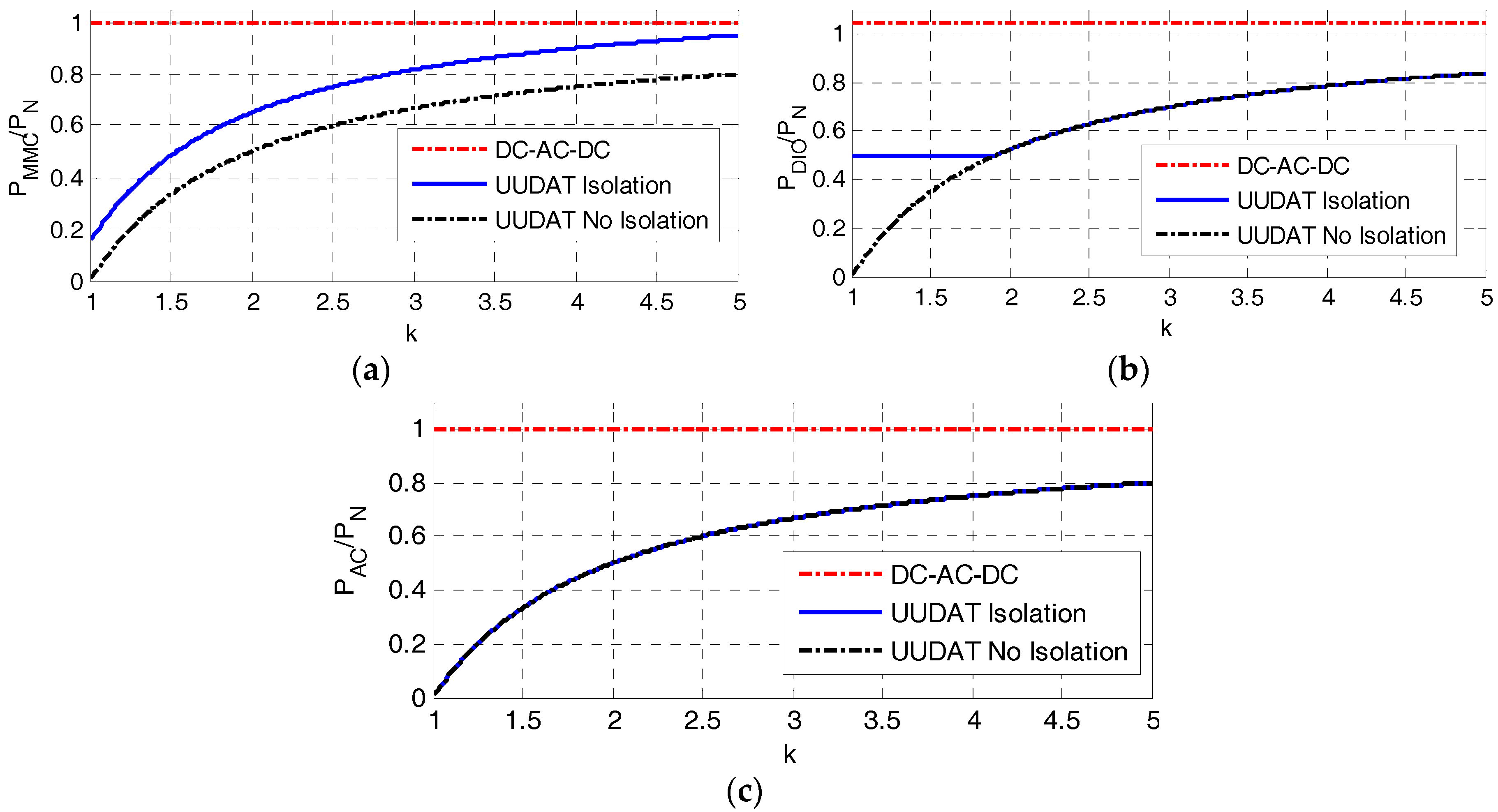
A step-up unidirectional DC AUTO (UUDAT) was briefly introduced in [
15] and investigated in [
28]. The UUDAT can reduce converter rating and operating power loss. This paper further expands the work of [
15,
28]. A unidirectional step-down DC AUTO (DUDAT) will be proposed. Pros and cons of the UUDAT and DUDAT will be analyzed in more detail. Possible applications of the unidirectional DC AUTOs will be discussed. Experimental results of a unidirectional DC AUTO prototype will also be presented, which are contributions that have not been reported in any reference of [
14,
15,
28] that studied DC AUTO technology.
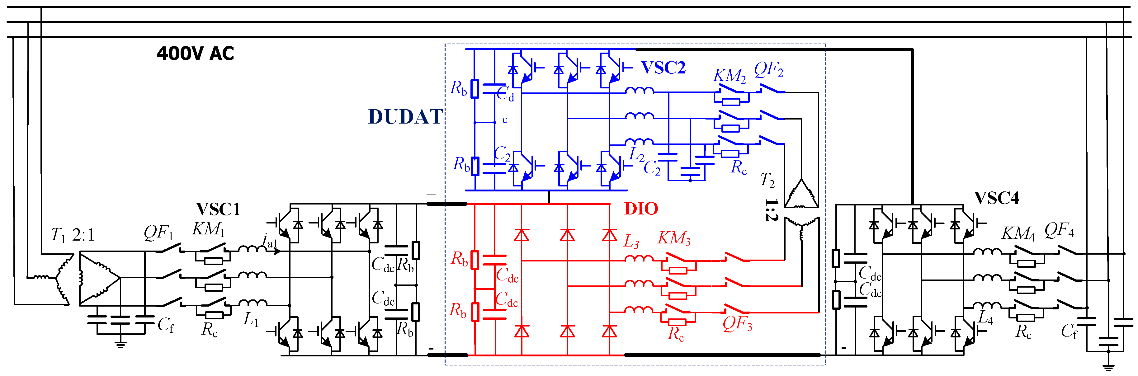
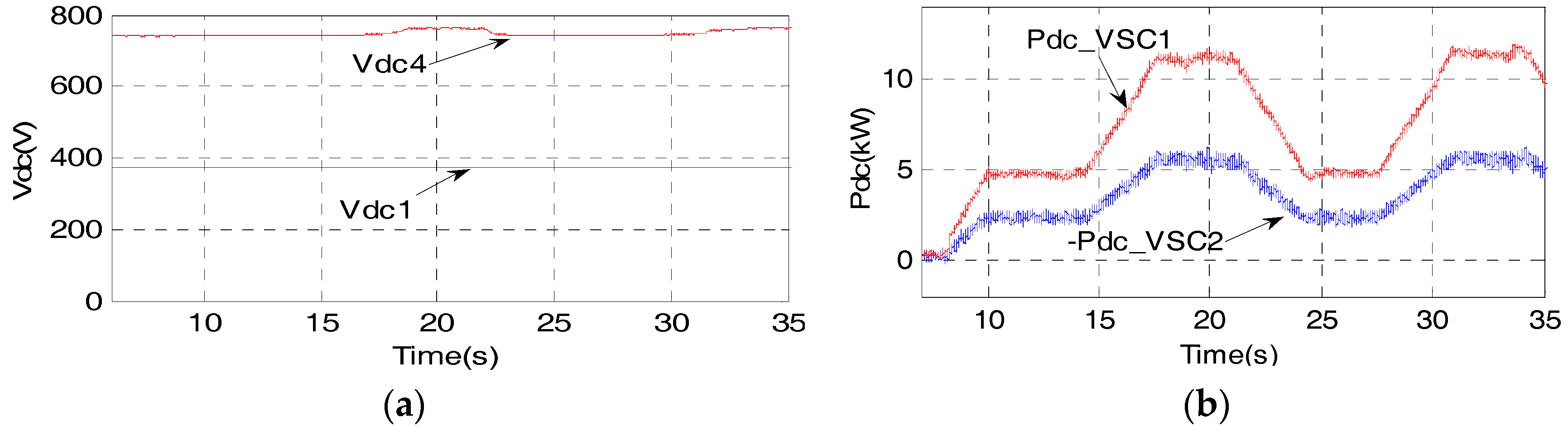
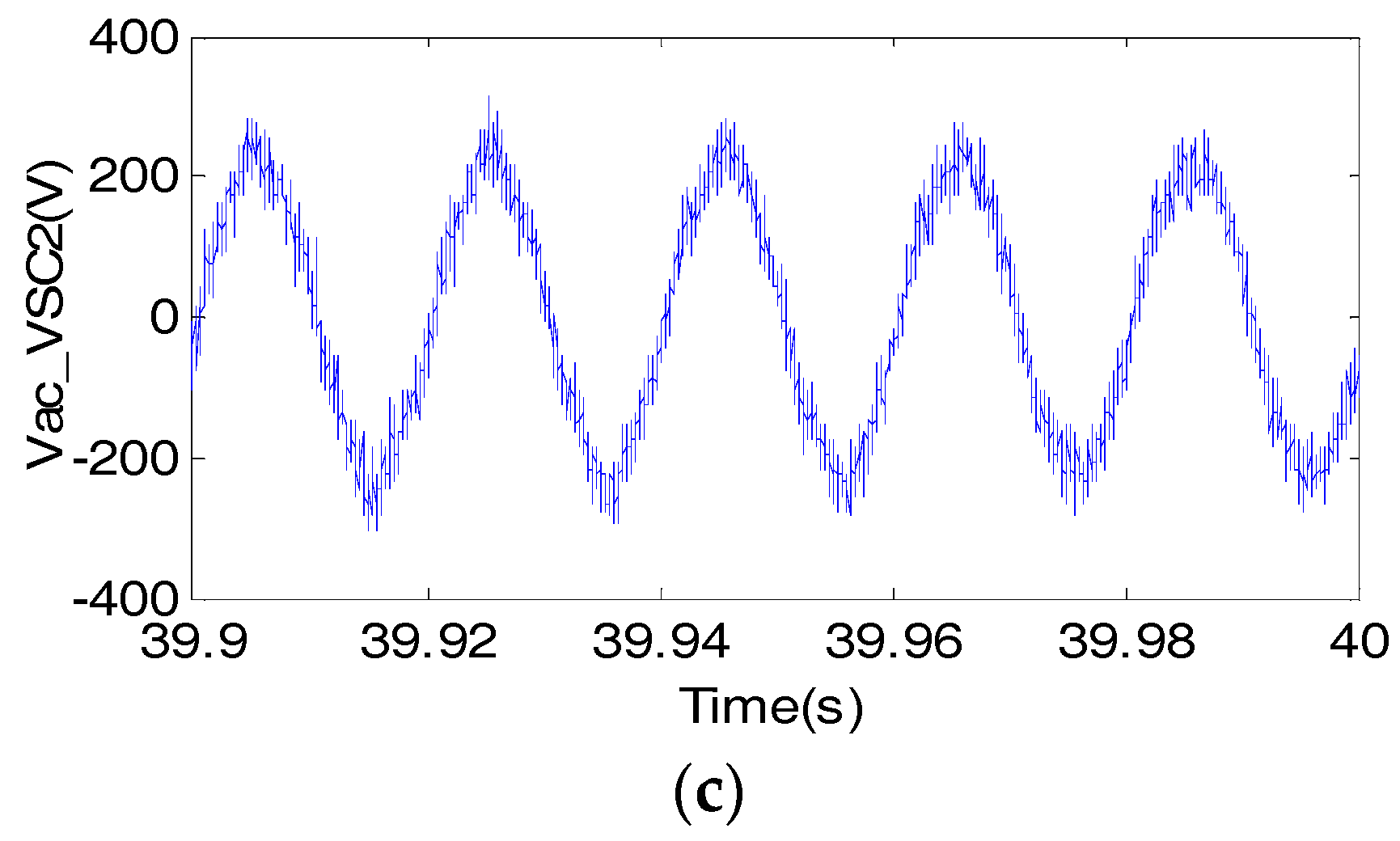
3. Control and Possible Application of the Unidirectional DC AUTO
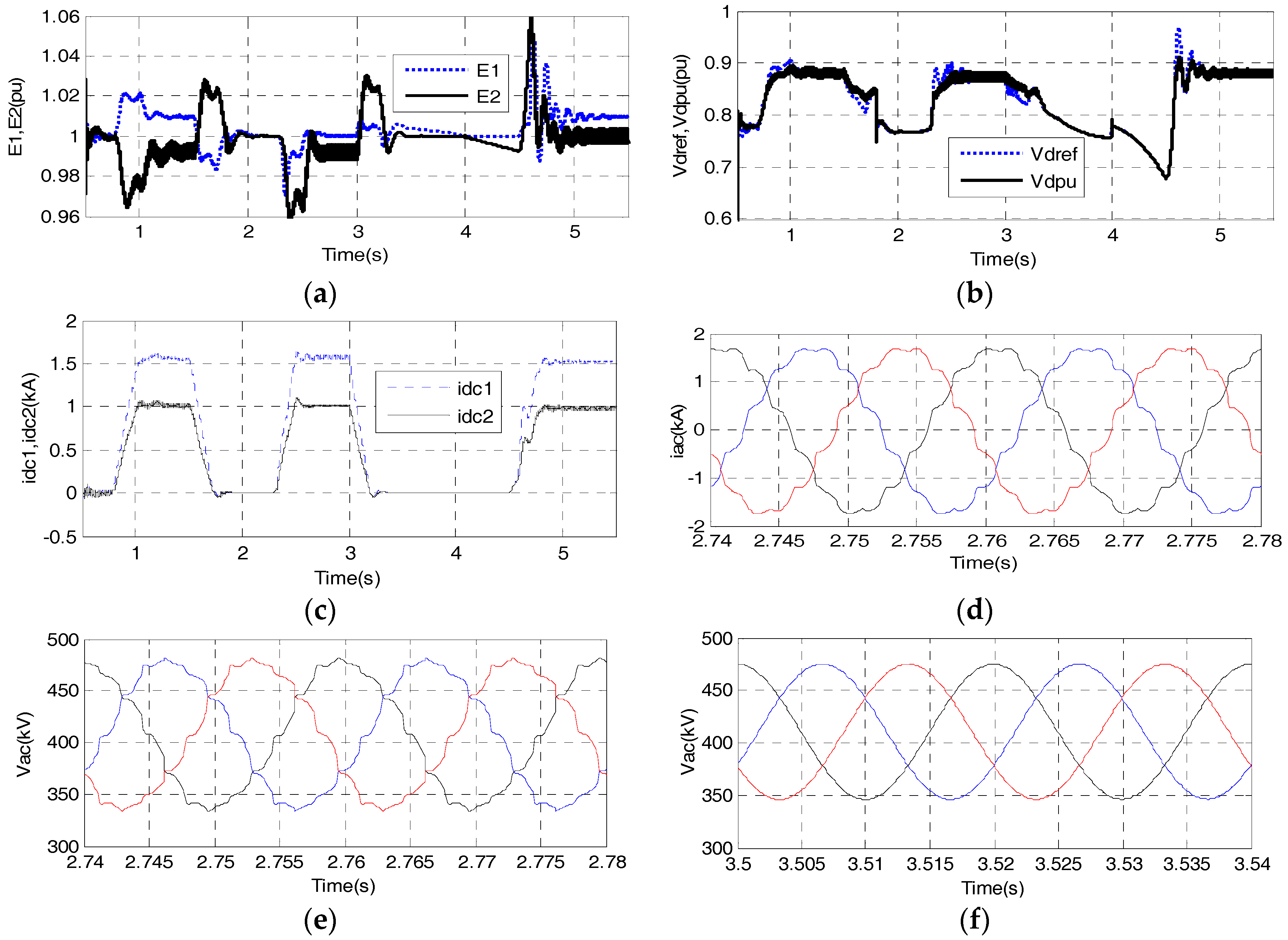
3.1. Control of UUDAT and DUDAT
For the UUDAT, by increasing the AC voltage of MMC2, the voltage rectified by DIO1, 3 can be increased. Thus,
E2 will be increased, which increases
idc2. Therefore, the DC power can be controlled by controlling the AC voltage in the UUDAT.
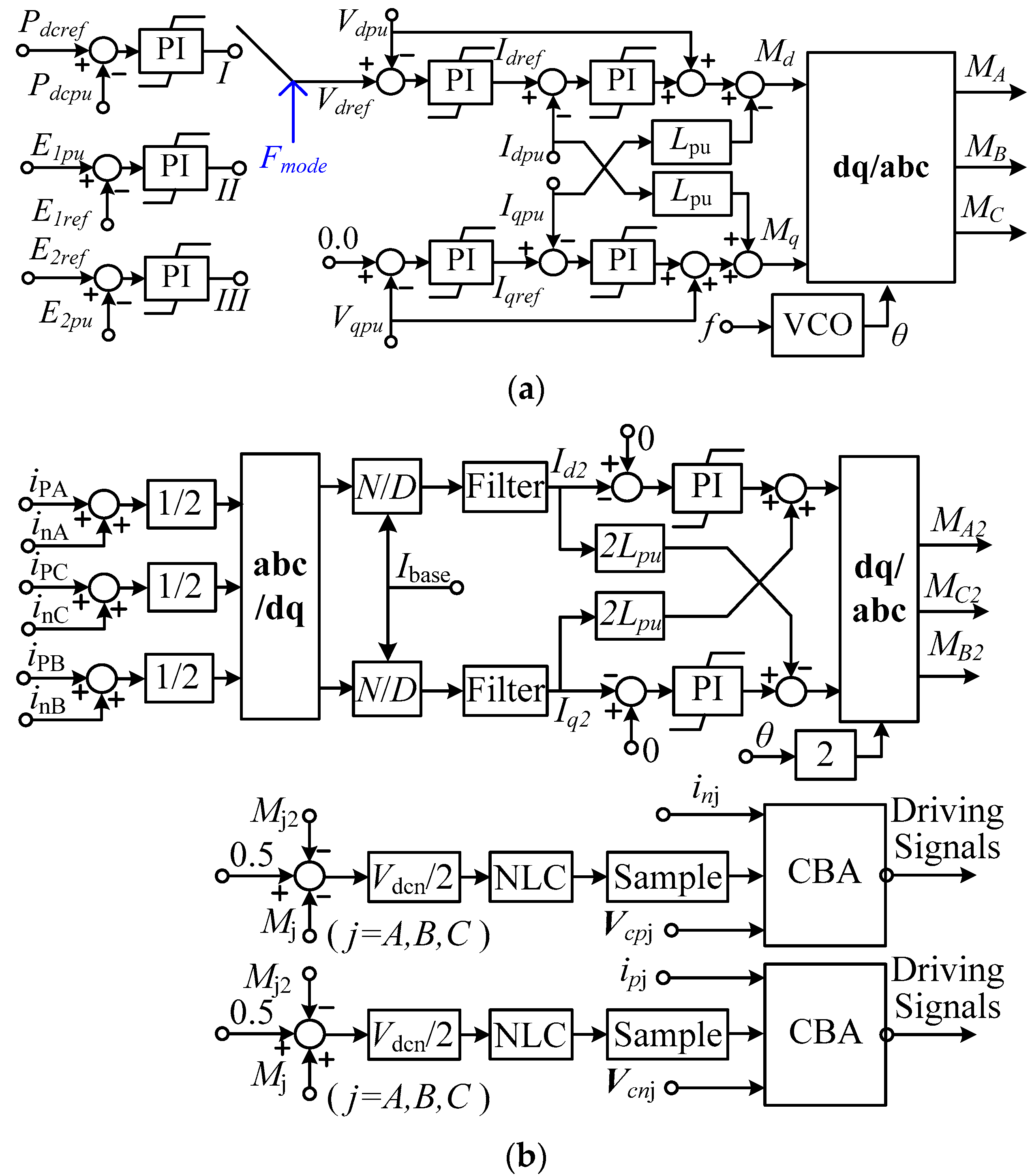
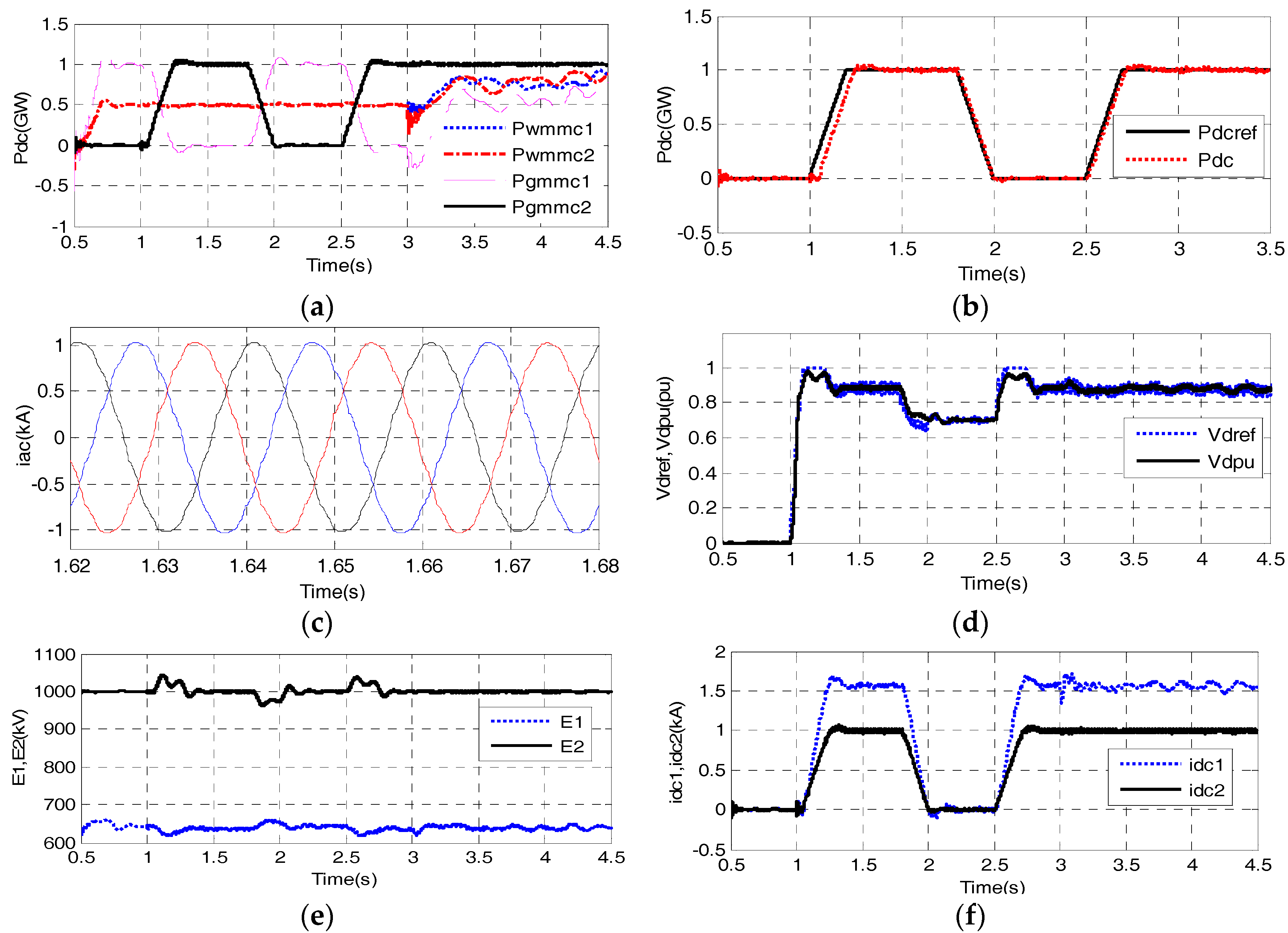
Figure 2 shows the upper layer control of UUDAT. The controller is composed of an outer loop DC power-DC voltage control, a middle loop AC voltage control and an inner loop AC current control. Outputs of the upper layer control are the modulation indices in abc frame, and a VCO (voltage-controlled oscillator) is used to provide reference angle for abc/dq transformation.
The UUDAT has three control modes, either to control its transferred DC power (mode I), control the DC voltage at the lower DC voltage side (mode II) or control the DC voltage at the higher DC voltage side (mode III). For mode II, by reducing the output AC voltage of MMC2, the DC power absorbed by UUDAT can be reduced and therefore E1 can be increased. Analysis of mode III is similar and will not be duplicated.
In
Figure 2a,
Pdcpu is the per unit value of the DC power. The positive DC current directions are shown in
Figure 1b,c.
Vdpu and
Vqpu are the dq component of the common bus AC voltage in a rotating dq frame.
Vdref is the reference value of
Vdpu.
Idpu and
Iqpu are the dq components of AC current
iA–
iC.
Lpu is the per unit value of reactance from inner electromotive force (EMF) point of an MMC to the common AC bus.
Md and
Mq are the dq modulation indices. The subscript pu of
Figure 2a stands for per unit value taking the rated value of each variable as the base value; the subscript ref stands for reference value.
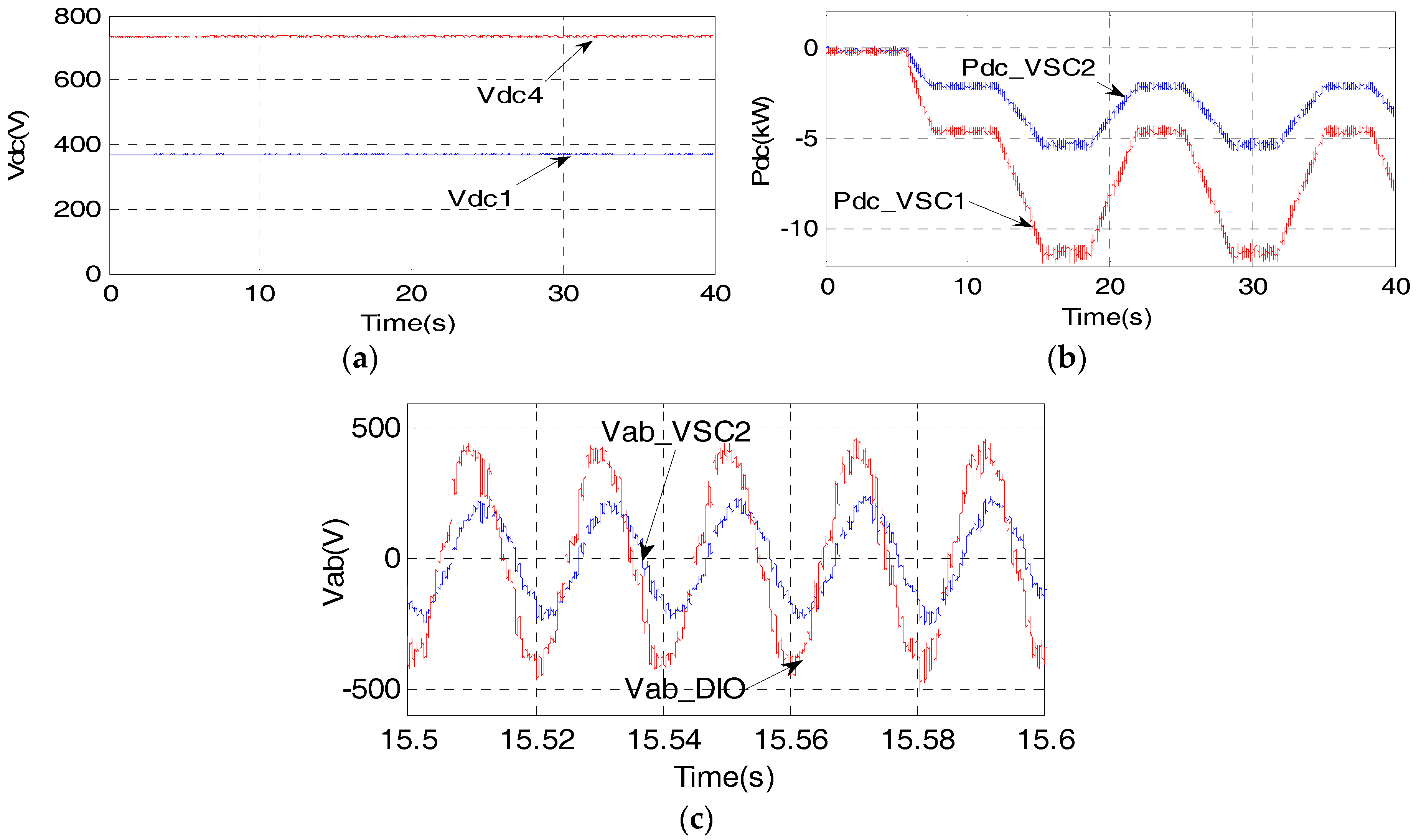
The upper layer control of the DUDAT is similar to the UUDAT and will not be duplicated.
Figure 2b shows the lower level control of MMC, which is composed of a circulating current suppressing control and a capacitor voltage balancing algorithm (CBA). The nearest level control modulation (NLC) and CBA based on soring with reduced switching frequency [
29] are employed. The output of NLC is sampled at the 5 kHz frequency.
3.2. Operation of UUDAT and DUDAT Interfaced to Passive Components at Load Side
The DC voltages at the lower and higher voltage sides are important for successful operation of UUDAT and DUDAT. When the load side of UUDAT is connected to passive components,
E2 will be clamped at
E1 if MMC2 is not in operation. After enabling the mode III control of
Figure 2a,
E2 can be controlled to its reference value. Therefore, the DC voltage at the load side of UUDAT can only vary from
E1 to rated value. The DC voltage at the load side of conventional unidirectional DC-AC-DC could vary from 0 to the rated value if the load side is connected to passive components. Since the UUDAT is dedicated to HVDC application, the operating scenario of interfacing the load side to passive components is very rare.
If the load side of DUDAT is connected to passive components, the DUDAT could not be started without over-dimensioning the voltage ratings of MMC1, 3 as during starting, all of the higher voltage side DC voltage is applied to the series connection of MMC1, 3. Since such an operating scenario is most likely to be unrealistic, the incapability of such an operating mode will not hamper the application of DUDAT.
3.3. Possible Application Scenario of UUDAT
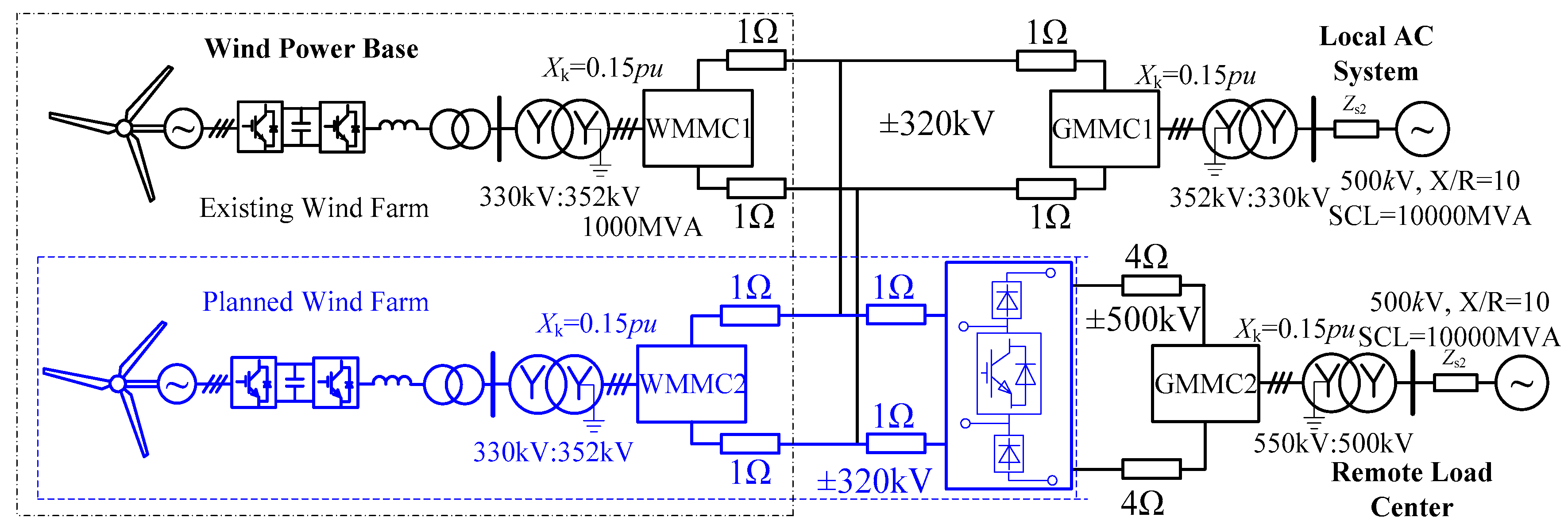
Figure 3 illustrates the possible application of UUDAT. It is used to transfer wind power from a low voltage DC system to a high voltage DC system. The parts inside the blue dash box belong to planned systems and the other parts belong to an existing system. The existing system includes a local ±320 kV lower voltage HVDC link that transfer wind power to a Local AC System and a ±500 kV HVDC passes through the region. The ±500 kV DC system supplies power to a Remote Load Center from a remote power center and has no electrical connection with the local region.
At a certain stage, the Wind Power Base plans a new wind farm. Since the Wind Power Base is remote from the Remote Load Center and the Local AC System is a weak AC system, HVDC will still be used to transfer the power of the planned wind farm. The voltage level of the new HVDC link needs to be determined. Since the Local AC System is not able to consume the total wind power from the existing wind farm and the planned wind farm, a new ±320 kV that only transfers power from the planned wind farm to the existing Local AC System will not be considered.
If a ±500 kV MMC is built and assumes that there is a long distance between the existing wind farm and planned wind farm, then the existing wind farm is not able to transfer DC power to the remote load center. An alternative scheme is to build a ±320 kV MMC and a ±320 kV/±500 kV UUDAT, as shown in the dashed box of
Figure 3. Such scheme has the benefit that:
Add the output power of the existing wind farm and planned wind farm to smooth the total output wind power and therefore reduce the impact of wind power oscillations on power system;
Enable more flexible power transmission, the power from both the existing wind farm and the planned wind farm could be transferred to either the Local AC System or to the Remote Load Center.
The system of
Figure 3 could well represent some of the key issues related to large-scale wind power grid integration in China [
30]. There is a large amount of wind power base in the west and north regions of China. In addition, each wind power base is composed of several wind farms scattered among a wide area. There are also several existing UHVDC links that are in the same region as these wind power bases. Majority of the wind power generated by these wind power bases are currently consumed by local AC network which is weak AC system, as the load centers are located in the east coast and south region of China. The system of
Figure 3 provides a reference to the practical issue of integrating large-scale wind power in China.


