On the Distribution of Lightning Current among Interconnected Grounding Systems in Medium Voltage Grids


1
Department of Energy, Information Engineering and Mathematical Models (DEIM)—University of Palermo, viale delle Scienze-Edificio 9, 90128 Palermo, Italy
2
Department of Industrial and Digital Innovation (DIID)—University of Palermo, viale delle Scienze-Edificio 8, 90128 Palermo, Italy
*
Author to whom correspondence should be addressed.
Energies 2018, 11(4), 771; https://doi.org/10.3390/en11040771
Submission received: 15 February 2018
/
Revised: 15 March 2018
/
Accepted: 22 March 2018
/
Published: 28 March 2018
(This article belongs to the Special Issue 17TH International Conference on Environment and Electrical Engineering)
Abstract
:This paper presents the results of a first investigation on the effects of lightning stroke on medium voltage installations’ grounding systems, interconnected with the metal shields of the Medium Voltage (MV) distribution grid cables or with bare buried copper ropes. The study enables us to evaluate the distribution of the lightning current among interconnected ground electrodes in order to estimate if the interconnection, usually created to reduce ground potential rise during a single-line-to-ground fault, can give place to dangerous situations far from the installation hit by the lightning stroke. Four different case studies of direct lightning stroke are presented and discussed: (1) two secondary substations interconnected by the cables’ shields; (2) two secondary substations interconnected by a bare buried conductor; (3) a high voltage/medium voltage station connected with a secondary substation by the medium voltage cables’ shields; (4) a high voltage/medium voltage station connected with a secondary substation by a bare buried conductor. The results of the simulations show that a higher peak-lowering action on the lighting-stroke current occurs due to the use of bare conductors as interconnection elements in comparison to the cables’ shields.
1. Introduction
In recent years, the effects of lightning discharge currents in electrical installations and in grounding systems have been extensively investigated in the scientific literature [1,2,3,4,5,6,7,8,9,10,11,12,13,14,15,16,17,18,19,20,21]. In particular, electromagnetic phenomena have been modeled in detail by the authors, also taking into account the transient performance of a Lightning Protection System (LPS) [22,23,24,25,26,27,28,29,30,31,32,33,34,35,36,37,38,39,40,41,42,43,44]. Lightning striking the external LPS of a building can be hazardous to humans due to the following factors:
- disruptive discharges in the insulation of electric components and devices;
- significant voltages between any two points of buildings ground-termination systems;
- high transient touch and step voltages in the building’s area.
Despite the use of LPSs and/or Surge Protective Devices (SPDs), lightning phenomena are still capable of damaging devices directly grounded or inside the protected area. The analysis of over-voltages in a residence due to a lightning strike to the ground and the establishment of effective countermeasures of damage mitigation have also been carried out through simulation models. Furthermore, it is necessary to consider the ground potential rise (GPR) due to lightning strike to the ground near the residence for the lightning protection design [45].
Even if the interconnection of ground electrodes belonging to different installations is a common technical practice for reducing the ground current and the voltage differences in case of ground fault [46], the distribution of the lightning current among various interconnected ground electrodes is a very important issue to be investigated. A previous work [47] presented an analysis of lighting current distribution in transmission overhead electrical line towers and ground wires, investigating in particular the effects of stroke-current waveshape on the crest-current magnitudes distribution. In Reference [48] the authors describe the frequency and time domain performance of an electrical substation ground electrode injected by a lightning stroke. Advanced computational models were implemented to simulate the response of grounding electrodes subject to lightning currents. In particular, it has been demonstrated how the frequency dependence of soil resistivity and permittivity strongly affects the accuracy of the obtained results [49]. In Reference [50] a frequency-domain methodology, developed for the calculation of electromagnetic transients, was applied to evaluate the direct incidence of an atmospheric discharge onto a transmission electrical line and the resulting overvoltages along the line. The work in Reference [51] presented a very detailed field study on lightning-stroke effects on electrical lines in distribution grids, focusing on the mechanisms that produce distribution line faults. In Reference [52] the authors performed an analysis and experimental verification of abnormal temporary overvoltages in radial ungrounded or resonant neutral medium voltage (MV) networks in the case of single-line-to-ground (1LtG) faults in long aerial lines or mixed cable-aerial lines.
As already underlined, the distribution of lightning current among various interconnected ground electrodes is a very important issue to be investigated. To this aim, our paper presents the results of a first investigation on the effects of lightning strokes on MV installations’ grounding systems, connected together with the metal shields of the MV distribution grid cables or with bare buried copper ropes. The study investigates the distribution of the lightning current among the interconnected ground electrodes in order to assess if the interconnection, normally established to reduce 1LtG faults current and the consequent GPR amplitudes, can give rise to dangerous situations far from the installation hit by a direct lightning stroke. In the following, after a description of the main modeling approaches and a brief introduction of the adopted simulation model, results related to four different effective application examples are reported and discussed:
- (1)
- two secondary substations interconnected by the cables’ shields;
- (2)
- two secondary substations interconnected by a bare buried conductor;
- (3)
- a high voltage/medium voltage station connected with a secondary substation by the medium voltage cables’ shields;
- (4)
- a high voltage/medium voltage station connected with a secondary substation by a bare buried conductor.
The remainder of the paper is structured as it follows:
- Section 2 describes the mathematical approach used for simulating the interconnected ground electrodes injected by the direct lightning stroke;
- Section 3 reports the four above-listed application examples;
- Section 4, finally, contains the conclusion of the work and a description of the future research.
2. Methodology
One of the most used approaches, useful for calculating the current distribution in an interconnected grounding system, is the circuit method. This approach is very easy to use and to implement but its major concerns are related to the correct evaluation of the circuit parameters. To this aim, Carson’s theory helps to provide some simplified formulas useful in power system analysis in the presence of frequency components not over 5 kHz [53,54,55]. As an example, if all of the frequency components are not over 5 kHz, the distribution of the current IL among any number N of interconnected ground electrodes can be easily found with reference to the ladder circuit shown in Figure 1, as done in Reference [56]. In Figure 1, RE is the ground resistance of the substations’ ground electrodes, ZS is the series impedance of the MV metal shields, ZES is the ground impedance of the station, and ZEO* is the equivalent driving point impedance of the ground wires connected to the station’s grounding grid.
The above equivalent ladder scheme can be assumed valid in the presence of insulated ground wires interconnecting the ground electrodes, with the aim of considering the global grounding system (GGS) framework during a fault [57]. When the current IL in Figure 1 is due to a direct lightning stroke, and cable shields are used as interconnection elements, the major issues concerning the use of the circuit approach are related to the high frequency components in the frequency spectrum of the lightning current, which are up to several hundreds of kHz. In this case, suitable expressions for the circuit impedances cannot be straightforwardly obtained. In order to overcome this constraint, a full-wave electromagnetic approach in the frequency domain can be successfully used.
Keeping in mind the above considerations, electromagnetic transients in the interconnected systems, made both of grounding electrodes and aerial parts (if dealing with an external LPS) driven by the lightning current, can be evaluated using a modified version of the thin-wire electric field integral equation in frequency domain, proposed by the authors in Reference [44]:
where:
- is the phasor of the axial conduction current in each wire of the interconnected structure;
- Ω is the domain of integration (i.e., the aerial and earthed wires of the structure and related complex images which take into account the half-space problem [44]);
- L is the length of the wire under consideration;
- is the magnetic permeability of the medium (air or soil);
- is the complex permittivity of the medium;
- and are the position vectors of the observation and source points, respectively;
- is the wave number;
- is the surface impedance of a straight cylindrical wire;
- ω = 2πf is the angular frequency;
- subscript “tg” indicates the evaluation of the tangential component (on the generic wire surface) of the electromagnetic quantities involved in Equation (1).
The previous equation is valid on the surface of each wire of the interconnected system. By imposing Equation (1) on a number of points on the surface of each wire, a linear system in the longitudinal unknown currents is obtained in the frequency domain. The solution of such a system for each frequency of the discretized Fourier spectrum of the lightning current source directly striking the wires structure enables us to obtain the frequency response of the whole wires system in terms of the selected electromagnetic quantities.
Time profiles are computed by using a discrete fast Fourier transform (DFFT) algorithm. As already outlined, this model takes into account coupling effects among aerial parts and ground electrodes. Therefore, it is possible to take into consideration both the insulated metal shield conductors and the grounding systems. The model has been tested and validated, as described in Reference [44]. The reader can refer to Reference [44], in which the validation of the proposed model (i.e., the possibility of considering the mutual coupling among aerial structures and buried electrodes in fast transient lightning conditions) is performed by comparing the results with those previously measured and computed, and available in the technical literature.
3. Application Examples
The analysis was carried out by considering two different scenarios. In the first scenario (scenario 1), the ground electrodes are connected by the metal shields of the MV cables, while in the second scenario (scenario 2), a bare buried copper conductor is considered as the interconnection element between the grounding systems. Moreover, for each scenario, two sub-cases are simulated and discussed:
- (1)
- a lightning directly striking an MV/LV substation connected to another MV/LV substation.
- (2)
- a lightning directly striking a High Voltage/Medium Voltage (HV/MV) station whose grounding grid is connected to the ground electrode of a supplied MV/LV substation.
For the first sub-case, two identical rectangular 3 × 6 m ground electrodes with four 1.5-m rods placed at the corners of the horizontal electrode are considered. This scenario is a typical for an MV/LV utility substations ground electrode. A current generator is supposed to directly inject the lightning current in one of the corners of the first electrode (Figure 2).
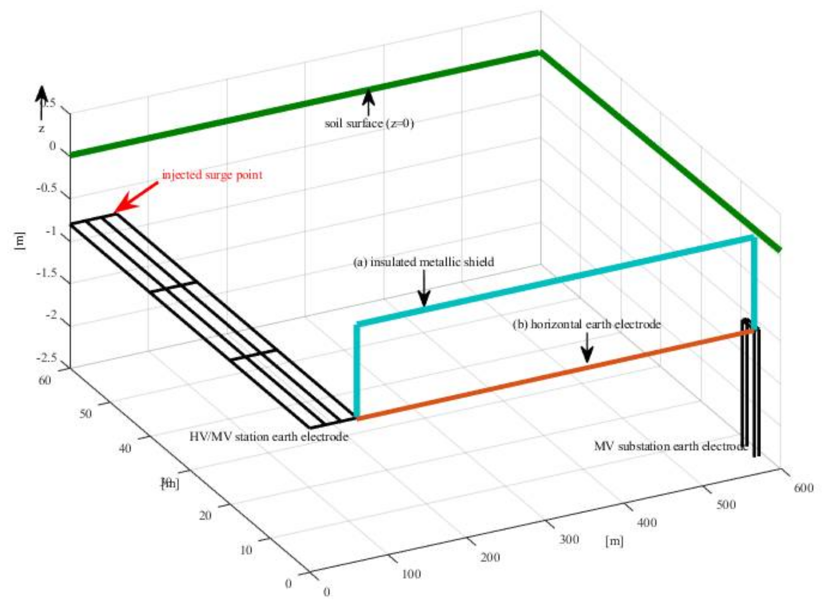
In the second sub-case, a square 60 × 60 m station’s ground electrode is connected to an MV/LV substation ground electrode with the same features selected in the previous subsection. Also in this case, the injected point is placed in one of the corners of the first electrode (Figure 3).
In both scenarios, only two interconnected grounding systems are considered, being the case that gives place both to the highest GPR and thermal solicitation of the interconnection element.
Table 1 summarizes the electrical and geometrical data of the two ground electrodes used in the following simulations.
The lightning peak current and the burial depth of the earth electrodes were set to be equal to 10 kA and 0.8 m, respectively. The adopted lightning current has a typical 1.2/50 μs/μs current time profile.
In the following, the results of the simulations for the four considered case studies are reported.
3.1. Scenario 1a. Direct Lightning Stroke to an MV/LV Substation in an MV line, Interconnection Setup by Insulated Metal Shields
It has been assumed that the grounding systems are interconnected by the metal shields of an MV line made by three standard single-core ARG7H1R 10/20 kV cables. This kind of cable, normally used for MV public distribution in Italy, has a copper shield with an equivalent cross-section equal to 6 mm2, thus the grounding systems are considered connected by an equivalent copper conductor with a cross section equal to 3 × 6 mm2. The electrical parameters of the equivalent interconnection elements are reported in Table 2.
Different situations have been investigated, by varying the value of the soil resistivity ρ and the distance d between the ground electrodes. By varying d, the metal shields input impedance varies, while the values are assumed for the resistivity influences of both the input impedance of the metal shields and the ground impedance of the interconnected ground electrodes.
In this first case, the equivalent metal shield, made by the three cables’ shields connected in parallel, is insulated from the soil.
Figure 4 shows the current flowing in the equivalent metal shield, for four values of the distance between the substations: 50 m, 100 m, 200 m, 500 m. For each distance the current is drawn for four different values of the soil resistivity: 100 Ω∙m, 500 Ω∙m, 1000 Ω∙m, 5000 Ω∙m, respectively.
The most relevant differences are summarized in Table 3, in which the peak currents Ip for all the cases are reported.
By considering the data shown in Table 3, a set of values for the reduction factor of the equivalent metal shield was evaluated and is reported in the Table 4. The classical definition of the reduction factor, as reported in IEC Std. 61936-1 [58], is given by the rate:
where:
- is the current in the metal shields (in the balanced stage);
- is the 1LtG current.
However, Equation (2) considers the root mean square values of the steady-state currents and is not applicable in the case of impulsive lightning currents. Therefore, for the present study the reduction factor was evaluated considering the peak current in the metal shields and the peak of the lightning-stroke current, even if the peaks do not occur at the same time.
The average reduction factor is rAVE = 0.56, thus it can be deduced, as expected, that the metal shields offer a low impedance path between the two grounding systems.
3.2. Scenario 1b. Direct Lightning Stroke to an HV/MV Station Whose Ground Electrode is Connected to That of an MV Substation, Interconnection Realized by Insulated Metal Shields
Figure 5 shows the time profiles of current flowing in the MV metal shields, by considering a soil resistivity equal to 100 and 5000 Ω∙m, respectively. As it is shown in scenario 1a, these two very different values are considered the most significant, in order to provide evidence of the different behavior of the metal shield in connecting an HV/MV station and an MV/LV substation. The distance between the two installations was set to be 500 m.
When a direct lightning stroke injects the HV/MV station, the majority of the current is injected into the soil by the station grounding system, whose lower ground resistance creates a preferential path for the leakage current.
It is worth noting that the current peak value flowing towards the MV/LV substation ground electrode is some percentage of the source current injected in the HV/MV station ground electrode: its value is equal about to 3% when the soil resistivity is set equal to 100 Ω∙m, and equal about to 13% when the soil resistivity is set equal to 5000 Ω∙m. This behavior is the same as that obtained in the case of a 1LtG fault, as expected [59].
In this case the values of the let-through energy of the metal shields are even lower than those reported in Table 5, therefore no significant thermal solicitation for the MV cables occurs. This situation becomes even more favorable when the grounding system of the station is connected to the metal shields of a large number of MV lines, as occurs in the technical practice.
3.3. Scenario 2a. Direct Lightning Stroke to an MV/LV Substation in an MV Line, Interconnection Realized by a Buried Bare Copper Rope
In Scenario 2 it was assumed that the grounding systems are interconnected by a copper rope buried in direct contact with the soil at the same depth as the ground electrodes. This situation can occur in the presence of a very high 1LtG fault current that is capable of damaging the MV cables’ metal shields. In those cases, the Distribution System Operator (DSO) installs the rope to reduce the percentage of the fault current that is injected in the metal shields during the fault, thus protecting the cables’ integrity. For the sake of simplicity, in this work the interconnection is considered realized only by the copper rope without considering the presence of the metal shields: this scenario may be useful for the setup of the heaviest design conditions of the horizontal buried wire. The electrical parameters of the rope are reported in Table 6.
Also in this case, the two subcases examined in Scenario 1a were simulated. In this case, contrary to the cables’ metal shields considered in Scenario 1a, the buried rope behaves as an auxiliary ground electrode.
Figure 6 shows the input and end currents in the copper rope, for a distance between the substations equal to 50 m and a soil resistivity varying from 100 Ω∙m to 5000 Ω∙m. Figure 7 shows the same currents for a distance equal to 100 m. Table 7 reports the peak currents Ip for all cases.
Similar trends can be found for distances equal to 200 m and 500 m. In each case, the current reaching the second grounding system is always lower than that injected in the buried rope. As expected, the difference between the input and the end currents is injected in the soil by the rope that behaves as an auxiliary electrode for the two interconnected substations.
Analogous to the Scenario 1a, Table 8 reports a set of values for the reduction factor of the rope.
The average reduction factor is rAVE = 0.28; thus, it can be deduced that a copper rope offers a very low impedance path between the two grounding systems and that this impedance value is lower than that in the case of interconnection achieved by the metal shields of the MV cables.
Finally, in this case, due to the injection of a part of the lightning-stroke current into the soil, the values of the let-through energy (I2t) in the rope for all of the investigated cases are almost 10% of those calculated in Scenario 1a in the presence of metal shields. The values are below the withstand energy of the rope (K2S2), evaluated according to IEC 61936-1 [58] and equal to 62.6 × 10⁶ A2s.
3.4. Scenario 2b. Direct Lightning Stroke to an HV/MV Station Whose Ground Electrode is Connected to That of an MV Substation, Interconnection Realized by a Buried Bare Copper Rope
Figure 8 and Figure 9 show the time profiles of current flowing in the copper rope, by considering a soil resistivity equal to 100 and 5000 Ω∙m and a distance between the two installations of 500 m.
In both figures, the input and the end currents in the rope are represented. In both cases, the rope is able to reduce the ground current at the station but it injects into the soil the whole current without any significant transmission towards the connected substation.
It is worth to notice that, also in this scenario, the current peak value flowing towards the MV/LV substation ground electrode is some percentage of the source current injected in the HV/MV station ground electrode: its value is equal about to 11% when the soil resistivity is set to 100 Ω∙m, and equal about to 44% when the soil resistivity is set to 5000 Ω∙m.
Also in this case, the values of the let-through energy of the bare buried rope are even lower than those in Table 5, therefore no significant thermal solicitation for the rope occurs.
Finally, in Appendix A the ground resistances for all the examined cases are reported.
4. Conclusions and Future Works
This study led to some important outcomes. When dealing with MV interconnected substations, the following results can be underlined:
- even though MV cables’ metal shields have a small cross-section, they provide a significant path to the lightning current, towards close electrical installations;
- the current flowing through the metal shields is influenced both by the distance between the grounding systems and by the soil resistivity. It ranges between 40% and 65% of the lightning current.
When the lightning stroke directly injects the ground electrode of an HV/MV station interconnected with an MV/LV substation, the majority of the current is injected into the soil by the station itself and a small current percentage flows towards the interconnected substation, if the ground electrodes are interconnected by cables’ metal shields. If the interconnection is achieved by a bare buried rope, a higher percentage of the lightning-strike current goes towards but does not reach to the substation, as it is also injected into the soil.
As a general remark, the thermal solicitation of the cables must be taken into consideration. Even if a high transient current is involved, the fast transient phenomena characterizing the lightning stroke may allow a natural protection against the unacceptable heating of the MV cables and bare buried ropes. On the contrary, it is noteworthy that a 1LtG fault current having the same peak value of the lightning current considered in this study can be very dangerous for the insulation of the MV cables, being interrupted by the station’s automatic circuit breaker in about 500 ms, i.e., in a greater time than that involved in transient lightning phenomena.
The above outcomes are very significant in the framework of the GGS. Indeed, a classical counter-argument to the GGS paradigm is that the interconnection between originally independent ground electrodes, although beneficial for the community, in some situations can lead to an increase of the risk level for end-users connected to the lower voltage level. This can be due, for example, to the transfer of dangerous potentials from HV/MV stations to unfaulted MV/MV or MV/LV substations. The dangerous potentials can arise due both to ground faults and to lightning currents from HV lines that, in the absence of interconnection, would not interest the grounding systems of the unfaulted substations. The study presented in this paper demonstrated that the risk increase due to potentials transfer between two interconnected ground electrodes following a lightning-strike current is practically null, especially when the interconnection is realized using bare rope buried directly in contact with the ground.
Moreover, the results obtained in the four examined scenarios are on the side of safety, given that in a real situation the number of interconnected ground electrodes is higher than two and, as a consequence, the lightning current usually splits into several parts. Therefore, the current transferred from the installation hit by lightning to another would be lower than any of the values calculated in this work.
In a future work, the same methodology will be applied to study the case of more interconnected ground electrodes in order to find suitable expressions of the driving point impedance offered by the chain of impedances, such as those shown in Figure 1. Moreover, it will be challenging to investigate whether the methodology commonly used to simulate interconnected ground electrodes when 1LtG fault occurs could be also applied to lightning studies.
Author Contributions
All the authors gave equal contributions in writing and revising the paper.
Conflicts of Interest
The authors declare no conflict of interest.
Nomenclature
| 1LtG | Single-line-to-ground |
| DFFT | Discrete fast Fourier transform |
| DSO | Distribution System Operator |
| GGS | Global Grounding System |
| GPR | Ground Potential Rise |
| HV | High Voltage |
| LPS | Lightning Protection System |
| LV | Low Voltage |
| MV | Medium Voltage |
| SPD | Surge Protective Device |
| TSO | Transmission System Operator |
Appendix A
Table A1, Table A2, Table A3 and Table A4 shows the ground resistances evaluated for the four configurations, according to the methods in IEEE Std. 80/2013 [59] for all of the examined configurations and ground resistivity.

Table A1.
Scenario 1a. Overall grounding resistance.
| Soil Resistivity | Distance | |||
|---|---|---|---|---|
| 50 m | 100 m | 200 m | 500 m | |
| 100 Ω∙m | 6.23 | 6.26 | 6.34 | 6.54 |
| 500 Ω∙m | 31.00 | 31.02 | 31.10 | 31.32 |
| 1000 Ω∙m | 61.94 | 61.98 | 62.06 | 62.28 |
| 5000 Ω∙m | 309.58 | 309.62 | 309.84 | 309.91 |
Table A2.
Scenario 1b. Overall grounding resistance.
| Soil Resistivity | Distance | |||
|---|---|---|---|---|
| 50 m | 100 m | 200 m | 500 m | |
| 100 Ω∙m | 0.86 | 0.86 | 0.87 | 0.87 |
| 500 Ω∙m | 4.31 | 4.32 | 4.32 | 4.32 |
| 1000 Ω∙m | 8.63 | 8.63 | 8.64 | 8.64 |
| 5000 Ω∙m | 43.16 | 43.16 | 43.17 | 43.17 |
Table A3.
Scenario 2a. Overall grounding resistance.
| Soil Resistivity | Distance | |||
|---|---|---|---|---|
| 50 m | 100 m | 200 m | 500 m | |
| 100 Ω∙m | 4.61 | 4.33 | 4.14 | 4.01 |
| 500 Ω∙m | 23.06 | 21.64 | 20.72 | 20.07 |
| 1000 Ω∙m | 46.13 | 43.28 | 41.43 | 40.14 |
| 5000 Ω∙m | 230.63 | 216.40 | 207.17 | 200.70 |
Table A4.
Scenario 2b. Overall grounding resistance.
| Soil Resistivity | Distance | |||
|---|---|---|---|---|
| 50 m | 100 m | 200 m | 500 m | |
| 100 Ω∙m | 0.86 | 0.84 | 0.82 | 0.80 |
| 500 Ω∙m | 4.30 | 4.20 | 4.11 | 4.00 |
| 1000 Ω∙m | 8.62 | 8.44 | 8.27 | 8.00 |
| 5000 Ω∙m | 43.15 | 42.09 | 40.86 | 39.97 |
References
- Zaini, N.; Ab Kadir, M.; Mohd Radzi, M.; Izadi, M.; Azis, N.; Ahmad, N.; Nasir, M. Lightning Surge Analysis on a Large Scale Grid-Connected Solar Photovoltaic System. Energies 2017, 10, 2149. [Google Scholar] [CrossRef]
- Hajeforosh, S.; Pooranian, Z.; Shabani, A.; Conti, M. Evaluating the High Frequency Behavior of the Modified Grounding Scheme in Wind Farms. Appl. Sci. 2017, 7, 1323. [Google Scholar] [CrossRef]
- Christodoulou, C.; Vita, V.; Voglitsis, D.; Milushev, G.; Ekonomou, L. A Heuristic Method for the Reduction of the Outage Rate of High-Voltage Substations Due to Atmospheric Overvoltages. Appl. Sci. 2018, 8, 273. [Google Scholar] [CrossRef]
- Wu, J.; Zhang, B.; He, J.; Zeng, R. A Comprehensive Approach for Transient Performance of Grounding System in the Time Domain. IEEE Trans. Electromagn. Compat. 2015, 57, 250–256. [Google Scholar] [CrossRef]
- Visacro, S.; Alipio, R.; Pereira, C.; Guimarães, M.; Schroeder, M.A.O. Lightning Response of Grounding Grids: Simulated and Experimental Results. IEEE Trans. Electromagn. Compat. 2015, 57, 121–127. [Google Scholar] [CrossRef]
- Visacro, S.; Rosado, G. Response of Grounding Electrodes to Impulsive Currents: An Experimental Evaluation. IEEE Trans. Electromagn. Compat. 2009, 51, 161–164. [Google Scholar] [CrossRef]
- Xiong, R.; Chen, B.; Gao, C.; Yi, Y.; Yang, W. FDTD Calculation Model for the Transient Analyses of Grounding Systems. IEEE Trans. Electromagn. Compat. 2014, 56, 1155–1162. [Google Scholar] [CrossRef]
- Sheshyekani, K.; Akbari, M.; Tabei, B.; Kazemi, R. Wideband Modeling of Large Grounding Systems to Interface with Electromagnetic Transient Solvers. IEEE Trans. Power Deliv. 2014, 29, 1868–1876. [Google Scholar] [CrossRef]
- Zhang, B.; Wu, J.; He, J.; Zeng, R. Analysis of Transient Performance of Grounding System Considering Soil Ionization by Time Domain Method. IEEE Trans. Magn. 2013, 49, 1837–1840. [Google Scholar] [CrossRef]
- Yuda, S.; Sawaki, S.; Baba, Y.; Nagaoka, N.; Ametani, A. Application of the TLM Method to Transient Simulations of a Conductor System with a Lossy Ground: Grounding Electrodes and an Overhead Wire. IEEE Trans. Electromagn. Compat. 2013, 55, 175–182. [Google Scholar] [CrossRef]
- Okabe, S.; Takami, J.; Nojima, K. Grounding System Transient Characteristics of Underground GIS Substations. IEEE Trans. Power Deliv. 2012, 27, 1494–1500. [Google Scholar] [CrossRef]
- Trlep, M.; Jesenik, M.; Hamler, A. Transient Calculation of Electromagnetic Field for Grounding System Based on Consideration of Displacement Current. IEEE Trans. Magn. 2012, 48, 207–210. [Google Scholar] [CrossRef]
- Yutthagowith, P.; Ametani, A.; Nagaoka, N.; Baba, Y. Application of the Partial Element Equivalent Circuit Method to Analysis of Transient Potential Rises in Grounding Systems. IEEE Trans. Electromagn. Compat. 2011, 53, 726–736. [Google Scholar] [CrossRef]
- Yamamoto, K.; Yanagawa, S.; Yamabuki, K.; Sekioka, S.; Yokoyama, S. Analytical Surveys of Transient and Frequency-Dependent Grounding Characteristics of a Wind Turbine Generator System on the Basis of Field Tests. IEEE Trans. Power Deliv. 2010, 25, 3035–3043. [Google Scholar] [CrossRef]
- Zeng, R.; Kang, P.; He, J.; Zhang, B.; Chen, S.; Zou, J. Lightning transient performance analysis of substation based on complete transmission line model of power network and grounding systems. IEEE Trans. Magn. 2006, 42, 875–878. [Google Scholar] [CrossRef]
- Zhang, B.; He, J.; Lee, J.-B.; Cui, X.; Zhao, Z.; Zou, J.; Chang, S.-H. Numerical analysis of transient performance of grounding systems considering soil ionization by coupling moment method with circuit theory. IEEE Trans. Magn. 2005, 41, 1440–1443. [Google Scholar] [CrossRef]
- Liu, Y.; Theethayi, N.; Thottappillil, R. An engineering model for transient analysis of grounding system under lightning strikes: Nonuniform transmission-line approach. IEEE Trans. Power Deliv. 2005, 20, 722–730. [Google Scholar] [CrossRef]
- Heimbach, M.; Grcev, L.D. Grounding system analysis in transients programs applying electromagnetic field approach. IEEE Trans. Power Deliv. 1997, 12, 186–193. [Google Scholar] [CrossRef]
- Grcev, L.D. Computer analysis of transient voltages in large grounding systems. IEEE Trans. Power Deliv. 1996, 11, 815–823. [Google Scholar] [CrossRef]
- Grcev, L.D.; Heimbach, M. Frequency dependent and transient characteristics of substation grounding systems. IEEE Trans. Power Deliv. 1997, 12, 172–178. [Google Scholar] [CrossRef]
- Heimbach, M.; Grcev, L.D. Grounding System Analysis in Transients Programs Applying Electromagnetic Field Approach. IEEE Power Eng. Rev. 1997, 17, 45–46. [Google Scholar] [CrossRef]
- Giglia, G.; Ala, G.; di Piazza, M.C.; Giaconia, G.C.; Luna, M.; Vitale, G.; Zanchetta, P. Automatic EMI Filter Design for Power Electronic Converters Oriented to High Power Density. Electronics 2018, 7, 9. [Google Scholar] [CrossRef]
- Di Piazza, M.C.; Luna, M.; Vitale, G.; Ala, G.; Giaconia, G.C.; Giglia, G.; Zanchetta, P. ODEF: An interactive tool for optimized design of EMI filters. In Proceedings of the 42nd Annual Conference of the IEEE Industrial Electronics Society, Florence, Italy, 24–27 October 2016; pp. 5013–5019. [Google Scholar]
- Ala, G.; Francomano, E.; Paliaga, M. Towards an efficient meshfree solver. AIP Conf. Proc. 2016, 1776, 1–4. [Google Scholar]
- Ala, G.; Giaconia, G.C.; Giglia, G.; di Piazza, M.C.; Luna, M.; Vitale, G.; Zanchetta, P. Computer aided optimal design of high power density EMI filters. In Proceedings of the 2016 IEEE 16th International Conference on Environment and Electrical Engineering, Florence, Italy, 7–10 June 2016. [Google Scholar]
- Ala, G.; Giaconia, G.C.; Giglia, G.; di Piazza, M.C.; Luna, M.; Vitale, G. Design and Performance Evaluation of a High Power-Density EMI Filter for PWM Inverter-Fed Induction-Motor Drives. IEEE Trans. Ind. Appl. 2016, 52, 2397–2404. [Google Scholar] [CrossRef]
- Ala, G.; Fasshauer, G.E.; Francomano, E.; Ganci, S.; McCourt, M.J. An augmented MFS approach for brain activity reconstruction. Math. Comput. Simul. 2017, 14, 3–15. [Google Scholar] [CrossRef]
- Pellitteri, F.; Ala, G.; Caruso, M.; Ganci, S.; Miceli, R. Physiological compatibility of wireless chargers for electric bicycles. In Proceedings of the 2015 International Conference on Renewable Energy Research and Applications (ICRERA), Palermo, Italy, 22–25 November 2015; pp. 1354–1359. [Google Scholar]
- Ala, G.; Francomano, E.; Ganci, S. Unconditionally stable meshless integration of time-domain Maxwell’s curl equations. Appl. Math. Comput. 2015, 255, 157–164. [Google Scholar] [CrossRef]
- Ala, G.; Francomano, E.; Fasshauer, G.E.; Ganci, S.; McCourt, M.J. A meshfree solver for the MEG forward problem. IEEE Trans. Magn. 2015, 51. [Google Scholar] [CrossRef]
- Ala, G.; Fasshauer, G.; Francomano, E.; Ganci, S.; McCourt, M.J. The method of fundamental solutions in solving coupled boundary value problems for M/EEG. SIAM J. Sci. Comput. 2015, 37, B570–B590. [Google Scholar] [CrossRef]
- Ala, G.; Giaconia, G.C.; Giglia, G.; di Piazza, M.C.; Vitale, G. Design and performance evaluation of a high power density EMI filter for PWM inverter-fed induction motor drives. In Proceedings of the 2015 IEEE 15th International Conference on Environment and Electrical Engineering, Rome, Italy, 10–13 June 2015; pp. 1573–1579. [Google Scholar]
- Ala, G.; di Paola, M.; Francomano, E.; Li, Y.; Pinnola, F.P. Electrical analogous in viscoelasticity. Commun. Nonlinear Sci. Numer. Simul. 2014, 19, 2513–2527. [Google Scholar] [CrossRef] [Green Version]
- Ala, G.; Francomano, E. Numerical Investigations of an Implicit Leapfrog Time-Domain Meshless Method. J. Sci. Comput. 2014, 62, 898–912. [Google Scholar] [CrossRef]
- Ala, G.; Cassarà, P.; Francomano, E.; Ganci, S.; Caruso, G.; Gallo, P.D. A numerical method for imaging of biological microstructures by VHF waves. J. Comput. Appl. Math. 2014, 259 Pt B, 805–814. [Google Scholar] [CrossRef] [Green Version]
- Ala, G.; Francomano, E. A multi-sphere particle numerical model for non-invasive investigations of neuronal human brain activity. Prog. Electromagn. Res. Lett. 2013, 36, 143–153. [Google Scholar] [CrossRef]
- Ala, G.; Francomano, E. A marching-on in time meshless kernel based solver for full-wave electromagnetic simulation. Numer. Algorithms 2013, 62, 541–558. [Google Scholar] [CrossRef]
- Ala, G.; Francomano, E. Smoothed particle electromagnetics modelling on HPC-GRID environment. Appl. Comput. Electromagn. Soc. J. 2012, 27, 229–237. [Google Scholar]
- Ala, G.; di Piazza, M.C.; Ragusa, A.; Viola, F.; Vitale, G. EMI analysis in electrical drives under lightning surge conditions. IEEE Trans. Electromagn. Compat. 2012, 54, 850–859. [Google Scholar] [CrossRef]
- Ala, G.; Francomano, E.; Viola, F. A wavelet operator on the interval in solving Maxwell’s equations. Prog. Electromagn. Res. Lett. 2011, 27, 133–140. [Google Scholar] [CrossRef]
- Ala, G.; Candela, R.; Viola, F. Detection of radiated EM transients by exploiting compact spherical antenna features. Recent Pat. Electr. Eng. 2011, 4, 202–208. [Google Scholar] [CrossRef]
- Ala, G.; Francomano, E.; Spagnuolo, A.; Tortorici, A. A meshless approach for electromagnetic simulation of metal carbon nanotubes. J. Math. Chem. 2010, 48, 72–77. [Google Scholar] [CrossRef]
- Ala, G.; Francomano, E.; Tortorici, A.; Toscano, E.; Viola, F. A mesh-free particle method for transient full-wave simulation. IEEE Trans. Magn. 2007, 43, 1333–1336. [Google Scholar] [CrossRef]
- Ala, G.; di Silvestre, M.L. A Simulation Model for Electromagnetic Transients in Lightning Protection Systems. IEEE Trans. Electromagn. Compat. 2002, 44, 539–554. [Google Scholar] [CrossRef]
- Sekioka, S.; Mori, K.; Fukazu, N.; Aiba, K.; Okabe, S. Simulation Model for Lightning Overvoltages in Residences Caused by Lightning Strike to the Ground. IEEE Trans. Power Deliv. 2010, 25, 970–978. [Google Scholar] [CrossRef]
- Colella, P.; Napoli, R.; Pons, E.; Tommasini, R.; Barresi, A.; Cafaro, G.; de Simone, A.; di Silvestre, M.L.; Martirano, L.; Montegiglio, P.; et al. Currents Distribution during a Fault in an MV Network: Methods and Measurements. IEEE Trans. Ind. Appl. 2016, 52, 4585–4593. [Google Scholar] [CrossRef]
- Johnson, L.B.; Price, W.S.; Schultz, A.J. Lightning-Current Distribution in Towers and Ground Wires. Trans. Am. Inst. Electr. Eng. Part III Power Appar. Syst. 1958, 77, 1414–1417. [Google Scholar] [CrossRef]
- Dawalibi, F.P.; Xiong, W.; Ma, J. Transient Performance of Substation Structures and Associated Grounding Systems. IEEE Trans. Ind. Appl. 1995, 31, 520–527. [Google Scholar] [CrossRef]
- Visacro, S.; Alipio, R. Frequency Dependence of Soil Parameters: Experimental Results, Predicting Formula and Influence on the Lightning Response of Grounding Electrodes. IEEE Trans. Power Deliv. 2012, 27, 927–935. [Google Scholar] [CrossRef]
- Salari, J.C.; Portela, C. A Methodology for Electromagnetic Transients Calculation—An Application for the Calculation of Lightning Propagation in Transmission Lines. IEEE Trans. Power Deliv. 2007, 22, 527–536. [Google Scholar] [CrossRef]
- Miyazaki, T.; Okabe, S. A Detailed Field Study of Lightning Stroke Effects on Distribution Lines. IEEE Trans. Power Deliv. 2009, 24, 352–359. [Google Scholar] [CrossRef]
- Cerretti, A.; Gatta, F.M.; Geri, A.; Lauria, S.; Maccioni, M.; Valtorta, G. Ground Fault Temporary Overvoltages in MV Networks: Evaluation and Experimental Tests. IEEE Trans. Power Deliv. 2012, 27, 1592–1600. [Google Scholar] [CrossRef]
- Olsen, R.G.; Jaffa, K.C. Electromagnetic Coupling from Power Lines and Magnetic Safety Analysis. IEEE Trans. Power Appar. Syst. 1984, PAS-103, 3595–3607. [Google Scholar] [CrossRef]
- Olsen, R.G.; Pankaskie, T.A. On the Exact, Carson and Image Theories for Wires at or Above the Earth’s Interface. IEEE Trans. Power Appar. Syst. 1983, PAS-102, 769–778. [Google Scholar] [CrossRef]
- IEEE Recommended Practice for Determining the Electric Power Station Ground Potential Rise and Induced Voltage from a Power Fault; Standard 367/2012; IEEE: Piscataway, NJ, USA, 2012.
- Campoccia, A.; Mineo, L.; Zizzo, G. A Method to Evaluate Voltages to Earth during an Earth Fault in an HV Network in a System of Interconnected Earth Electrodes of MV/LV Substations. IEEE Trans. Power Deliv. 2008, 23, 1763–1772. [Google Scholar] [CrossRef]
- Campoccia, A.; Zizzo, G. Simple circuit models for studying Global Earthing Systems. In Proceedings of the 2007 IEEE Lausanne Power Tech, Lausanne, Switzerland, 1–5 July 2007. [Google Scholar]
- Power Installations Exceeding 1 kV a,c,—Part 1: Common Rules; 61936-1; IEC: Geneva, Switzerland, 2014.
- IEEE Guide for Safety in AC Substations Grounding; Standard 80-2013/Cor 1-2015; IEEE: Piscataway, NJ, USA, 2015.
Figure 1.
Equivalent ladder circuit model for the evaluation of the single-line-to-ground (1LtG) fault current distribution from an High Voltage/Medium Voltage (HV/MV) station to the supplied secondary substations.
Figure 1.
Equivalent ladder circuit model for the evaluation of the single-line-to-ground (1LtG) fault current distribution from an High Voltage/Medium Voltage (HV/MV) station to the supplied secondary substations.

Figure 2.
Scenario 1—Direct lightning stroke to an MV/LV substation in an MV line. (a) Interconnection realized by insulated metal shields; (b) Interconnection by a horizontal earth electrode.
Figure 2.
Scenario 1—Direct lightning stroke to an MV/LV substation in an MV line. (a) Interconnection realized by insulated metal shields; (b) Interconnection by a horizontal earth electrode.

Figure 3.
Scenario 2—Direct lightning stroke to an HV/MV station. (a) Interconnection realized by insulated metal shields; (b) Interconnection by a horizontal earth electrode.
Figure 3.
Scenario 2—Direct lightning stroke to an HV/MV station. (a) Interconnection realized by insulated metal shields; (b) Interconnection by a horizontal earth electrode.

Figure 4.
Current time profiles in the equivalent 3 × 6 mm2 metal shields. The distance between the substations is set equal to: (a) 50 m; (b) 100 m; (c) 200 m; (d) 500 m.
Figure 4.
Current time profiles in the equivalent 3 × 6 mm2 metal shields. The distance between the substations is set equal to: (a) 50 m; (b) 100 m; (c) 200 m; (d) 500 m.

Figure 5.
Current time profiles of the equivalent 3 × 6 mm2 metal shields. The distance between the HV/MV station and the MV/LV substation is set equal to 500 m.
Figure 5.
Current time profiles of the equivalent 3 × 6 mm2 metal shields. The distance between the HV/MV station and the MV/LV substation is set equal to 500 m.

Figure 6.
Current time profiles in the copper rope. The distance between the substations is set equal to 50 m. (a) soil resistivity 100 Ω∙m; (b) soil resistivity 500 Ω∙m; (c) soil resistivity 1000 Ω∙m; (d) soil resistivity 5000 Ω∙m.
Figure 6.
Current time profiles in the copper rope. The distance between the substations is set equal to 50 m. (a) soil resistivity 100 Ω∙m; (b) soil resistivity 500 Ω∙m; (c) soil resistivity 1000 Ω∙m; (d) soil resistivity 5000 Ω∙m.

Figure 7.
Current time profiles in the copper rope. The distance between the substations is set equal to 100 m. (a) soil resistivity 100 Ω∙m; (b) soil resistivity 500 Ω∙m; (c) soil resistivity 1000 Ω∙m; (d) soil resistivity 5000 Ω∙m.
Figure 7.
Current time profiles in the copper rope. The distance between the substations is set equal to 100 m. (a) soil resistivity 100 Ω∙m; (b) soil resistivity 500 Ω∙m; (c) soil resistivity 1000 Ω∙m; (d) soil resistivity 5000 Ω∙m.

Figure 8.
Current time profiles of the copper rope. The distance between the HV/MV station and the MV/LV substation is set equal to 500 m (soil resistivity 100 Ω∙m).
Figure 8.
Current time profiles of the copper rope. The distance between the HV/MV station and the MV/LV substation is set equal to 500 m (soil resistivity 100 Ω∙m).

Figure 9.
Current time profiles of the copper rope. The distance between the HV/MV station and the MV/LV substation is set equal to 500 m (soil resistivity 5000 Ω∙m).
Figure 9.
Current time profiles of the copper rope. The distance between the HV/MV station and the MV/LV substation is set equal to 500 m (soil resistivity 5000 Ω∙m).

Table 1.
Electrical and geometrical data of the ground electrodes for the two selected scenarios.
| MV/LV Substation Ground Electrode | |
| Sides length | 6 × 3 m |
| Material | Copper |
| Cross-section | 35 mm2 |
| Electrical resistivity | 17.8 Ω mm2/km |
| Series distributed resistivity | 0.54 Ω/km |
| HV/MV station ground electrode | |
| Sides length | 60 × 60 m |
| Mesh size | 20 × 20 m |
| Material | Copper |
| Cross-section | 35 mm2 |
| Electrical resistivity | 17.8 Ω mm2/km |
| Series distributed resistivity | 0.54 Ω/km |
Table 2.
MV cables characteristics.
| Cable Type | ARG7H1R 12/20 kV |
|---|---|
| Shield’s material | Copper |
| Equivalent shield’s cross-section | 3 × 6 mm2 |
| Electrical resistivity | 17.8 Ω mm2/km |
| Series distributed resistivity | 1.088 Ω/km |
Table 3.
Peak currents in amperes due to lightning stroke in the MV cables.
| Peak Current Ip (A) | ||||
|---|---|---|---|---|
| 50 m | 100 m | 200 m | 500 m | |
| 100 Ω∙m | 4270 | 3940 | 3630 | 3537 |
| 500 Ω∙m | 4750 | 4640 | 4520 | 3863 |
| 1000 Ω∙m | 4820 | 4780 | 4700 | 4052 |
| 5000 Ω∙m | 4920 | 4801 | 4797 | 4608 |
Table 4.
Reduction factor of the metal shields.
| Reduction Factor | ||||
|---|---|---|---|---|
| 50 m | 100 m | 200 m | 500 m | |
| 100 Ω∙m | 0.57 | 0.61 | 0.64 | 0.65 |
| 500 Ω∙m | 0.53 | 0.54 | 0.55 | 0.61 |
| 1000 Ω∙m | 0.52 | 0.52 | 0.53 | 0.59 |
| 5000 Ω∙m | 0.51 | 0.52 | 0.52 | 0.54 |
Table 5.
Let-through energy due to lightning strike in the MV cables.
| I2t (A2s) | ||||
|---|---|---|---|---|
| 50 m | 100 m | 200 m | 500 m | |
| 100 Ω∙m | 7.99 × 10² | 7.69 × 10² | 7.33 × 10² | 7.77 × 10² |
| 500 Ω∙m | 8.31 × 10² | 8.25 × 10² | 8.16 × 10² | 8.61 × 10² |
| 1000 Ω∙m | 8.35 × 10² | 8.32 × 10² | 8.27 × 10² | 9.27 × 10² |
| 5000 Ω∙m | 8.40 × 10² | 8.42 × 10² | 8.51 × 10² | 1.28 × 10³ |
Table 6.
Copper rope characteristics.
| Material | Copper |
|---|---|
| Equivalent shield’s cross-section | 35 mm2 |
| Electrical resistivity | 17.8 Ω mm2/km |
| Series distributed resistivity | 0.54 Ω/km |
Table 7.
Peak currents in amperes due to a lightning stroke at the beginning of the copper rope between two interconnected MV/LV substations.
Table 7.
Peak currents in amperes due to a lightning stroke at the beginning of the copper rope between two interconnected MV/LV substations.
| Peak Current Ip (A) | ||||
|---|---|---|---|---|
| 50 m | 100 m | 200 m | 500 m | |
| 100 Ω∙m | 5890 | 5890 | 5890 | 5890 |
| 500 Ω∙m | 7000 | 7220 | 7240 | 8240 |
| 1000 Ω∙m | 7270 | 7660 | 7706 | 7710 |
| 5000 Ω∙m | 7490 | 8280 | 8560 | 8570 |
Table 8.
Reduction factor of the copper rope.
| Reduction Factor | ||||
|---|---|---|---|---|
| 50 m | 100 m | 200 m | 500 m | |
| 100 Ω∙m | 0.41 | 0.41 | 0.41 | 0.41 |
| 500 Ω∙m | 0.30 | 0.28 | 0.28 | 0.18 |
| 1000 Ω∙m | 0.27 | 0.23 | 0.23 | 0.23 |
| 5000 Ω∙m | 0.25 | 0.17 | 0.14 | 0.14 |
© 2018 by the authors. Licensee MDPI, Basel, Switzerland. This article is an open access article distributed under the terms and conditions of the Creative Commons Attribution (CC BY) license (http://creativecommons.org/licenses/by/4.0/).
Share and Cite
MDPI and ACS Style
Ala, G.; Favuzza, S.; Francomano, E.; Giglia, G.; Zizzo, G. On the Distribution of Lightning Current among Interconnected Grounding Systems in Medium Voltage Grids. Energies 2018, 11, 771. https://doi.org/10.3390/en11040771
AMA Style
Ala G, Favuzza S, Francomano E, Giglia G, Zizzo G. On the Distribution of Lightning Current among Interconnected Grounding Systems in Medium Voltage Grids. Energies. 2018; 11(4):771. https://doi.org/10.3390/en11040771
Chicago/Turabian StyleAla, Guido, Salvatore Favuzza, Elisa Francomano, Graziella Giglia, and Gaetano Zizzo. 2018. "On the Distribution of Lightning Current among Interconnected Grounding Systems in Medium Voltage Grids" Energies 11, no. 4: 771. https://doi.org/10.3390/en11040771
Note that from the first issue of 2016, this journal uses article numbers instead of page numbers. See further details here.